1
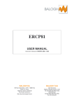
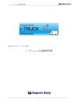
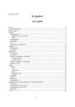
GIR Titan-Hyperion
Installer manual
www.gir.fr/en
[email protected]
Version 1.0-6, january 2007
2
c 2004-2007 klervi. All rights reserved.
Copyright °
Any reproduction or translation of part or totality of this manual is
forbidden without any prior written authorization from klervi.
The contents of this document are given for information only. Klervi
is in no way liable for any mistake that could have slipped into the
text.
Contents
1 General information
1.1 Protections . . . . . . . . . . . . . .
1.2 Installation procedure . . . . . . . .
1.2.1 First installation . . . . . . .
1.2.2 Update, machine change . . .
1.2.3 Access from another machine
1.3 Administration page . . . . . . . . .
1.3.1 Table formatting . . . . . . .
1.3.2 CSV Import/Export . . . . .
.
.
.
.
.
.
.
.
.
.
.
.
.
.
.
.
.
.
.
.
.
.
.
.
.
.
.
.
.
.
.
.
.
.
.
.
.
.
.
.
.
.
.
.
.
.
.
.
.
.
.
.
.
.
.
.
.
.
.
.
.
.
.
.
.
.
.
.
.
.
.
.
.
.
.
.
.
.
.
.
.
.
.
.
.
.
.
.
.
.
.
.
.
.
.
.
.
.
.
.
.
.
.
.
.
.
.
.
.
.
.
.
.
.
.
.
.
.
.
.
.
.
.
.
.
.
.
.
7
7
7
7
8
8
8
9
9
2 Configuration
2.1 General parameters . . . . . .
2.1.1 Installer config. . . . .
2.1.2 Products . . . . . . .
2.1.3 Access types . . . . .
2.2 Sites . . . . . . . . . . . . . .
2.3 Tanks . . . . . . . . . . . . .
2.4 CPUs . . . . . . . . . . . . .
2.4.1 Pumps . . . . . . . . .
2.4.2 Terminals . . . . . . .
2.4.3 Readers . . . . . . . .
2.4.4 4I4O . . . . . . . . . .
2.4.5 232 modules . . . . . .
2.4.6 Fuel sets . . . . . . . .
2.4.7 Access sets . . . . . .
2.4.8 Configuration validity
2.5 Values range . . . . . . . . .
2.6 Specific badges . . . . . . . .
.
.
.
.
.
.
.
.
.
.
.
.
.
.
.
.
.
.
.
.
.
.
.
.
.
.
.
.
.
.
.
.
.
.
.
.
.
.
.
.
.
.
.
.
.
.
.
.
.
.
.
.
.
.
.
.
.
.
.
.
.
.
.
.
.
.
.
.
.
.
.
.
.
.
.
.
.
.
.
.
.
.
.
.
.
.
.
.
.
.
.
.
.
.
.
.
.
.
.
.
.
.
.
.
.
.
.
.
.
.
.
.
.
.
.
.
.
.
.
.
.
.
.
.
.
.
.
.
.
.
.
.
.
.
.
.
.
.
.
.
.
.
.
.
.
.
.
.
.
.
.
.
.
.
.
.
.
.
.
.
.
.
.
.
.
.
.
.
.
.
.
.
.
.
.
.
.
.
.
.
.
.
.
.
.
.
.
.
.
.
.
.
.
.
.
.
.
.
.
.
.
.
.
.
.
.
.
.
.
.
.
.
.
.
.
.
.
.
.
.
.
.
.
.
.
.
.
.
.
.
.
.
.
.
.
.
.
.
.
.
.
.
.
.
.
.
.
.
.
.
.
.
.
.
.
.
.
.
.
.
.
.
.
.
.
.
.
.
.
.
.
.
11
12
12
13
14
14
14
15
17
19
20
20
20
21
24
26
27
27
.
.
.
.
.
.
.
.
.
.
.
.
.
.
.
.
.
.
.
.
.
.
.
.
.
.
.
.
.
.
.
.
.
.
.
.
.
.
.
.
.
.
.
.
.
.
.
.
.
.
.
.
.
.
.
.
.
.
.
.
.
.
.
.
.
.
.
.
3 CPU communication
31
3.1 Configuration sending . . . . . . . . . . . . . . . . . . . . . . . . 31
3.2 Addressing options . . . . . . . . . . . . . . . . . . . . . . . . . . 31
A Link test files content
33
A.1 Configuration summary . . . . . . . . . . . . . . . . . . . . . . . 33
A.2 Data report . . . . . . . . . . . . . . . . . . . . . . . . . . . . . . 38
3
4
CONTENTS
Introduction
GIR Titan-Hyperion is a fleet management software. It covers fuel delivery,
assignment of vehicles to drivers, vehicles maintenances, access to the station
or to buildings.
5
6
CONTENTS
Chapter 1
General information
1.1
Protections
Accessing GIR Titan-Hyperion with an installer account is protected by a
dongle. The control is done when connecting to the application: once a connection has been established, the dongle may be removed. The default installer
account is root/install.
If the dongle is not detected (Message “Dongle not found” on connection, or
“Access denied” when accessing the Fdisk page), install the drivers available on
the installation cd. Those drivers are not necessary on every configuration, so
they should not be installed when not needed.
Each version of GIR Titan-Hyperion is compiled specifically for a given customer, with a customer and an installer key:
• The customer key protects the database access: a database can’t be copied
from a customer to another.
• The installer key identifies the dongle: opening a database with an installer
account is only possible for the customer’s accredited installer.
1.2
1.2.1
Installation procedure
First installation
1. Run GIR Titan-Hyperion’s installation wizard, and install the application
in the directory of your choice (c:\hyperion by default).
2. If GIR proximity badges files are available, copy them to c:\hyperion\data\dti
(Assuming c:\hyperion is the installation directory).
3. Create an empty database (requires the dongle):
• Right-click the GIR Titan-Hyperion icon in the taskbar, then select
the Admin menu.
• Click on Format (Fdisk)
7
8
CHAPTER 1. GENERAL INFORMATION
• Select ALL
• Click on Format and wait for the end of the operation. (A complete
format can last up to several minutes)
4. If a database is available (as a TWB file), import the file using the Restore
button in the administration page.
5. Connect to the application in installer mode (User: root, Password:
install) with the dongle.
6. Define the configuration (See chapter 2).
7. Initialize CPUs with sequence files, and send the configuration (See chapter 3).
8. Do a link test and make sure that all modules are responding.
9. If necessary, create the minimal data to carry out a transaction (a vehicle,
a driver, . . . ), and launch a Retr.-Send dialogue to send the data.
10. Carry out transactions on CPUs.
11. Launch a Retr.-Send dialogue to retrieve the transactions, then check the
consistency of retrieved data.
12. Optionnally, create the remaining data (departments, vehicles, . . . ), as
well as a user account for the manager.
13. Connect with the manager account and launch a Retr.-Send dialogue.
1.2.2
Update, machine change
Application update and machine change are described in the “Exceptional operations” chapter of the user manual.
1.2.3
Access from another machine
Once the installation is completed, GIR Titan-Hyperion can be accessed from
another machine on the network, using the url:
http://<server_address>:8080/cgi-bin/twcgibin.exe?p=4747
<server_address> is the ip address or hostname of the computer on which the
application is installed. 8080 and 4747 are the default ports of the web server
and the GIR Titan-Hyperion application.
1.3
Administration page
The administration page is a special url in GIR Titan-Hyperion, that can be
used without opening a database. This page can be accessed either by the
Admin menu using the taskbar icon, or by appending &admin=1 at the end of
an url. Under Windows, the administration page can only be accessed from the
machine where GIR Titan-Hyperion is running.
The following features are available on this page:
1.3. ADMINISTRATION PAGE
9
Format (Fdisk): Formats the tables (installer only)
CSV: CSV file import or export (installer only)
Check tables: Shows database information.
Backup: Creates a database backup in a TWB file.
Restore: Restores a database from a TWB file.
Repair tables: Repairs database.
Table conversion: Database version update.
Sessions: Lists the users currently logged on.
SAV: Uses HTTP to upload or download files with GIR’s after-sales-service.
The Fdisk and CSV operations are only available in installer mode. The
dongle is checked at each step of these operations.
These operations will be the only two detailed in this document, the other
ones being described in the user manual (“Exceptional operations” chapter).
1.3.1
Table formatting
This operation formats the selected table, and creates the associated file if necessary. If a file already exists for this table, it will be overwritten. By default,
a database backup is done before any formatting operation.
The ALL item allows to format all the tables to create an empty database.
The Create a mini. cfg option automatically creates a CPU, a pump, and
their dependencies. After that, the only remaining steps before lauching a dialogue are defining communication settings and creating a vehicle and a driver.
1.3.2
CSV Import/Export
This operation converts tables from or into csv files.
The export operation creates a dbxNNN.csv file for each table, in the selected
directory. It also creates a readme.txt file, containing the symmetry between
file numbers and tables names.
The import operation read all the files whose name matches dbxNNN.csv in
the selected directory, and imports those files into the corresponding tables.
For instance, csv import and export can be used to export a database to
another application, do some processing, then re-import the result in GIR TitanHyperion.
10
CHAPTER 1. GENERAL INFORMATION
Chapter 2
Configuration
GIR Titan-Hyperion configuration is made of one or several sites. Each site can
contain one or several CPUs and tanks. TIP CPUs can be used for both fuel
and access management. Depending on the desired usage, a certain number of
fuel and access sets will be defined on each CPU.
A fuel set is a logical unit dedicated to fuel delivery. It is made of:
• A terminal for display and data entry
• Badge readers
• One or several pumps
• Printers
Similarly, an access set is a logical unit dedicated to access management:
Site A
CPU 1
Tank 1
Fuel set
Pump 1
Site B
CPU 2
Tank 2
CPU 3
Access set
Tank 3
Fuel set
Pump 2
Pump 1
Pump 2
GIR Titan-Hyperion configuration is made through the following steps:
1. General parameters definition
2. Sites definition
11
12
CHAPTER 2. CONFIGURATION
3. Tanks definition
4. CPUs definition, with for each CPU:
• Modules creation
• Modules aggregation into a fuel set or access set
2.1
2.1.1
General parameters
Installer config.
B Config., Installer config.
First id: Defines the first item asked when entering a manual transaction (Vehicle
or Driver ). It is recommanded to use the same identification order as on
CPUs.
General options:
• Enable proxi. file.: This option should be enabled when the badges
used are GIR proximity badges. It allows to initialize badges using
a proximity file. See the “Data entry” chapter in the user manual for
more information.
• Local zones: Enables local zones management. This adds the Local
zone field in fuel and access sets, and tabs in vehicles and drivers
sheets. See the user manual for more information.
• Vehicle badge on 16 , Driver badge on 16 , Nick on 20 : Increases the
size of the corresponding fields.
• Data import by manager : Allows the manager to use initial data import.
• Disable ext. tr. export: Don’t export external fuelings.
CPUs options:
• Code + Secret code vehicles, Code + Secret code drivers: These options allow to enter a secret code in addition to the identification for
vehicles and drivers. See the “Data entry” chapter in the user manual
for more information.
• Numerical drivers code: This option allows to keep a 6-digits driver
code when using the Code + Secret code drivers mode (TIP1-Pabbay
only).
• Force driver id. by code, Force vehicle id. by code: Forces code identification for all vehicles (resp. drivers), ignoring their individual
configuration.
• Vehicle auth. by direction: Allows to define direction-based vehicles
authorizations for drivers, instead of department-based authorizations.
• Show cons. graph.: Displays over and under-consumption on the CPU
(TIP2-Vatersay only, when consumption display is enabled).
2.1. GENERAL PARAMETERS
13
• 16 products max.: Limit the total number of products in the software
to 16. This speeds up data processing on large databases.
• Per-driver language: Shows the CPU language field in drivers, to
change the CPU language when a driver is identified (TIP2-Vatersay
only).
Config. options:
• Ignore modified config. on tanks tresholds: Don’t set CPUs to the
“modified config.” state when the alert treshold is modified. The
alert treshold on CPUs is only use for live printing.
Real-time tempo: Defines real-time dialogues frequency. The higher the frequency is, the faster the transactions are retrieved. However, when transactions are very frequent, the application can become less available for
users.
Real-time opt.:
• Retr. seule: Only use real-time dialogues for transaction retrieval. If
so, data sending should be definine using auto. progs.
Authorizations v/d: Defines the mode to use for authorization of vehicles to
drivers: by department, direction, or departments group.
Hour meters unit (TIP) : Defines the entry unit for hour meters on TIP CPUs:
1/100H, 1/10H or H.
TIP CPUs messages section: These fields change the messages displayed on
TIP CPUs.
GC90 CPUs messages section: These fields change the messages displayed on
GC90 CPUs.
Terminology section: These fields change the terms used in the software.
2.1.2
Products
B Config., Products
Nom: Name used to refer to a product in the software and on CPU.
Ref.: Value used to refer to a product in specific exports.
P.U. min., P.U. max.: Unit price validity range for this product. It is used
when entering a tank supply or a manual transaction, to control the value
of the entered data, for example to avoid an inversion between volume and
unit price.
Sale unit, Sale unit name: Value and name of the sale unit for this product.
When these values are defined, an additionnal column is displayed in the
tanks state.
Type: Product type (Fuel , Washing , Other ), used to filter transactions in their
history.
14
CHAPTER 2. CONFIGURATION
Options:
• Disable traclient export: Causes transactions with this product to be
ignored in traclient exports.
2.1.3
Access types
B Config., Access types
Name: Name used to refer to an access type in the software.
Ref: Value used to refer to an access type in specific exports.
Character: Character used to identify an access type on the live printer (TIP2Vatersay only).
Source state name: For bistable accesses, name of the system state before this
access type is done (e.g. “Enabled” or “Disabled” for an alarm). These
names are displayed in the supervision screen (TIP2-Vatersay only).
2.2
Sites
B Config., Sites
Short name, Full name: Names used to refer to a site in the software.
Ref.: Value used to refer to a site in specific exports.
Region: Assigned region (Only when the corresponding feature is enabled in
the Manager config.).
2.3
Tanks
B Config., Tanks
Site: Related site.
Short name, Full name: Names used to refer to a tank in the software.
Ref.: Value used to refer to a tank in specific exports.
Product: Tank’s product
Blocking treshold: Stock below which the pumps using this tank are automatically blocked.
Alert treshold: Stock below which an alert is generated.
Current stock, U.P.: Current tank stock and unit price of this stock. Those
values can’t be modified directly. After creating a tank, they must be
set by entering a supply (See the “Operations entry” chapter in the user
manual).
Capacity: Total tank capacity.
2.4. CPUS
15
Compartments: Compartments contain a tank’s gauging configuration. Up
to 4 independant compartments can be defined for each tank. When a
tank has a gauge and only one compartment, compartment 1 should be
used.
Each compartment has the following fields:
Mod. 232 gauge: Gauge module associated to the compartment (the module and the
CPU must have been previously created).
Gauge type, Probe num.: Gauge settings.
Capacity: Compartment capacity.
Offset: Offset used to shift heights read by the gauge module.
Options:
– Computed by Hyperion: Forces the volume to be computed by
the software when retrieving gauging data. When this option is
enabled, the only values used from the gauge are the fuel height,
the water height, and the temperature.
Gauges alerts, Gauges options: Alert generation tresholds (See the “Configuration” section of the “Data entry” chapter, in the user manual).
When a tank has a gauge module, it is also necessary to fill the associated
abacuses table, in the tank sheet.
→ Conventions:
• Tanks names: Tank 1, Tank 2, . . .
• Blocking treshold: Empty by default (no blocking).
• Alert treshold: 0 L by default.
Note: When a tank name is displayed, the name of its product is automatically appended. Hence, it is not necessery to repeat the product name in the
tank name.
2.4
CPUs
B Config., CPUs
Num.: Number automatically assigned to each CPU by GIR Titan-Hyperion.
It is unique to each CPU.
Site: CPU site.
Short name, Full name: Names used to refer to the CPU in the software.
Ref.: Value used to refer to a CPU in specific exports.
Adr.: CPU address.
16
CHAPTER 2. CONFIGURATION
Password: (TIP2-Vatersay only) Defines the password to use during dialogues
with this CPU. It must have been previously set in the CPU configuration
menu.
Type: CPU type and link. The CPU type depends on the management unit
used. For old hardware, some software features might not be available.
GIR Titan-Hyperion supports the following models:
• GC90 : Old hardware, supported for compatibility.
• TIP1-Pabbay : Intermediate hardware, most features available.
• TIP2-Vatersay : New hardware, all features available.
The link defines the performance of communications between PC and
CPU. Some links are only available for a specific cpu type. The following
configurations are available:
• net: full TCP networking
• 232 : 57600 bauds, full-duplex
• 485 : 57600 bauds, half-duplex
• x19 : 19200 bauds, half-duplex
• x9 : 9600 bauds, half-duplex
Link type: PC-CPU link type: network, serial or modem.
Link param.: Link parameters. Their parsing by GIR Titan-Hyperion depends
on the link type:
• TCP: <host>:<port>. The host name may be an IP address or a
DNS name (e.g. 192.168.0.123:6001).
• Serial : <comX> where X is a serial port number (e.g. com1).
• Modem: <comX>:<tel>[:<atdt>[:<at&f>]] where X is the serial
port on which the modem is connected, and tel is the phone number
to dial (e.g. com2:0478741234). The successive commands sent to
the modem are:
1. atz
2. Command specified in the fourth parameter (at&f by default)
3. Command specified in the third parameter followed by the phone
number (atdt by default)
Mode: Synchronisation mode between GIR Titan-Hyperion and the CPU (TIP
CPUs only).
• Autonomous: Connection with the CPU is temporarily established
during dialogues, which can be manually or automatically launched.
• Real time: Connection with the CPU is permanent. Transactions are
retrieved in real time by the software, and data is regularly synchronized.
2.4. CPUS
17
• Autonomous without auto. conn.: Identical to the autonomous mode,
except for the supervision screen where the user must explicitly ask
for the connection to the CPU.
Sequence file: Name of the sequence file to use. The sequence files are searched
in the seq sub-directory. The sequence file to use can be chosen among a
list of the available files, in B Config., Sequence update.
Language: Defines the language to use one the CPU. By default, the language
used is the same as in the software.
Timezone: Defines the CPU timezone, if it differs from the software timezone.
Options:
• Forbidden: Disables a cpu without deleting it.
In addition to those settings, a CPU is made of multiple modules, assembled
into fuel or access sets. Modules and sets are available using the different tabs
in the CPU sheet. The General tab displays a summary of the configuration.
→ Conventions:
• CPUs names: CPU 1, CPU 2, . . .
2.4.1
Pumps
IO num.: Module address (from 0 to 15)
Name: Pump name, used to refer to the pump in the software, and displayed
on the terminal, on the pump selection confirmation screen.
Ref.: Value used to refer to a pump in specific exports.
Product: Product delivered by the pump.
Tank 1, Tank 2: Tanks in which the pump takes fuel. The first tank is mandatory, except for fake pumps (see below). The second tank should be set
only for mixed products.
Ratio: When two tanks are defined, indicates the product percentage taken
from tank 2.
Start T.: Delivery starting temporization (see below).
End T.: Delivery ending temporization (see below).
Counter:
• Simple: One counting channel
• Double: Two counting channels
• Bidirectional : Two counting channels, counting positively or negatively given the pulses order.
• Double (Add): Two counting channels, adding the pulses count on
both channels.
18
CHAPTER 2. CONFIGURATION
• Simple (Up+Down): One counting channel, on ascending and descending fronts (doubles the number of pulses).
• Double (Up+Down): Two counting channels, on ascending and descending fronts (doubles the number of pulses).
Hangup:
• On opening : Contact is opened when the pump nozzle is hanged up.
• On closing : Contact is closed when the pump nozzle is hanged up.
• Auto: The hangup type is automatically detected during the first
fueling.
Tops: Number of tops per liter for the counting device (from 1 to 10 000).
Coefficient: Coefficient to apply when sending a tops per liter value to the
CPU. This is usefull to customize the range of available values for specific
configurations (See 2.5, page 27). When such a coefficient is defined, the
volume displayed on the terminal is not the real volume.
Type: Pump type
• Delivery : Pump used for fuel delivery. The volume measured is deducted from the stock of the associated tank.
• Decanting : Decanting pump. A transaction done on this pump will
be stored with a negative volume and the tank stock will be increased
instead of decreased.
• Fake: Allows to use a pump module to control other devices (e.g. in
a washing station). A fake pump must not be related to any tank. A
transaction done on this pump won’t deduct any stock, and will be
assigned a 1 liter volume.
• Vol. enterd on CPU: Fake pump, with manual entry of the volume on
the CPU terminal.
• No tank: Pump without an assigned tank (e.g. washing).
Max. duration (normal), Max. duration (restrict.): Maximum transaction duration, under normal and restricted modes (TIP2-Vatersay only, see below). Zero means “Unlimited”.
Options:
• Forbidden in restricted mode: Makes the pumps unavailable under
restricted mode (TIP2-Vatersay only).
Totalizer: See user manual.
→ Conventions:
• Pumps names (unless the customer uses a specific convention): Pump 1,
Pump 2, . . .
Note: When a pump name is displayed, either on the terminal or in the
software, its product name is automatically appended. Hence, it is not necessary
to repeat the product name in the pump name.
2.4. CPUS
19
Temporizations and max. duration
The Start T., End T. and Max. duration fields define how a transaction is temporized.
Start T. is the time after which a transaction is stopped if no fuel has been
delivered since the pump was commanded. End T. is the time after which a
transaction is stopped if no fuel has been delivered once a first fueling was
detected. Those temporizations are detailed in the “CPU usage” chapter of the
user manual.
Max. duration is the maximum time that a transaction can take, it is the
same whether fuel is taken or not. For TIP1-Pabbay CPUs, it is defined in
the fuel set. For TIP2-Vatersay CPUs, it is defined per pump, and can change
under restricted mode.
For all cases, a zero value means that the associated temporization is unlimited.
Washing station: These temporizations can be used to control the washing
duration on a washing station.
For TIP1-Pabbay CPUs, the maximum duration has an influence on all the
pumps of a given set. The washing duration should then be defined by the
delivery starting temporization.
For TIP2-Vatersay CPUs, it is recommanded to use the Max duration field,
which is pump-specific.
2.4.2
Terminals
IO num.: Module address (from 0 to 15)
Nom: Module name
Keyboard: Keyboard type. For TIP CPUs, the valid keyboard types are TIP,
GIR 12 keys and SECME .
Password char.: Character displayed on the terminal when a code is entered.
End T.: Entry ending temporization: inactivity timeout after which an entry
is automatically cancelled.
Options:
• 40 columns, 4 lines: Terminal display format. Standard TIP terminals have 20 columns and 2 lines.
→ Conventions:
• Modules names: x-Term 1, x-Term 2, . . .
Where x is the letter of the set in which the terminal is being used.
20
CHAPTER 2. CONFIGURATION
2.4.3
Readers
The modules defined in the Readers tab are GIR proximity badges readers. They
can also be used to control an access point. Other badges readers are defined
using 232 modules.
IO num.: Module address (from 0 to 15)
Name: Module name
Type: Reader type (Marin 125 kHz by default)
→ Conventions:
• Reader modules names: x-Prox 1, x-Prox 2, . . .
• Reader modules names when used as access control: x-Relay 1, x-Relay
2, . . .
Where x is the letter of the set in which the reader is being used.
2.4.4
4I4O
Modules “4 inputs 4 outputs”.
IO num.: Module address (from 0 to 15)
Name: Module name
→ Conventions:
• Modules names: x-4I4O 1, x-4I4O 2, . . .
Where x is the letter of the set in which the module is being used.
2.4.5
232 modules
232 modules provide an interface to a RS-232 device. They can be used to cover
a large variety of needs: reader, printer, gauge . . .
IO num.: Module address (from 0 to 15). For TIP2-Vatersay CPUs, values 16
to 31 are also valid, and allow to use a USB/RS-232 converter directly
plugged to the management unit. The adress/port map is detailled in
appendix to this document.
Name: Module name
Speed, Format, Stop bits: Parameters of the serial connection.
Options:
• CR: Adds a carriage return character (\’r’) at the end of strings sent,
and removes it at the end of strings received (TIP1-Pabbay only).
The configuration to use on 232 modules for different devices is detailed in
appendix to this document.
2.4. CPUS
21
→ Conventions:
• Names of readers modules: x-Rdr 1, x-Rdr 2, . . . where x is the letter
of the set in which the reader is being used.
• Names of printer modules: Print 1, Print 2, . . . for shared printers.
x-Print 1, x-Print 2, . . . for printers assigned to a single set, where x
is the letter of the set.
• Names of gauge modules: Gauge 1, Gauge 2, . . .
2.4.6
Fuel sets
Specific reader
Printers
Proximity reader
Terminal
Fuel set
Pump 1
Pump 2
Pump 3
IO num.: Fuel set number
Name: Fuel set name
Terminal: Fuel set terminal module.
First id: Defines the first identification (Vehicle or Driver ) asked before a fueling.
GIR proxi reader, Spec. reader 1, Spec. reader 2: GIR proximity reader and
specific readers. Specific readers must be associated to badges formats and
identifiers (See 2.6, page 27). If those three readers are (N/A), only the
identification by code will be available.
Spec. 1 type, Spec. 2 type: Special badges management (TIP2-Vatersay only).
Special badges types are detailled in appendix to this document.
Opt. proxi., Opt. spec. 1, Opt. spec. 2:
• Disabled on vehicle id., Disabled
on driver id.: Disables the reader in the corresponding identification
context.
• Debug id.: For special badges, enables logging of detailled information
in the CPU Logs.
22
CHAPTER 2. CONFIGURATION
First pump, Last pump: Pumps related to the fuel set. All pump modules
with an IO num. between those of the selected pumps will be considered
as members of the fuel set.
Min. time null vol.: Minimum transaction duration to consider it as a null volume.
Null vol. before block.: Number of consecutive null volumes before blocking a
pump.
Live printer: 232 module for the live printer
Ticket printer: 232 module for the ticket printer
Ticket begin, Ticket end: Ticket printer control strings (ascii-hexa), sent respectively before and after the ticket data.
Show volume: Displays the volume on the terminal during the delivery. (N/A)
means “no display”.
Vol. duration: Volume display duration at the end of a transaction (TIP2Vatersay only).
Cons. duration: Consumption display durationn at the end of a transaction
(TIP2-Vatersay only).
Max. duration: Maximum transaction duration. Zero means “unlimited” (TIP1Pabbay only, see 2.4.1, page 19)
Time offset: Defines an offset to apply when a date is read on a badge (TIP2Vatersay with special badges only).
Anonymous tacho. downl. freq: Download frequency for tachograph cards downloaded anonymously.
Options:
• Show last meter : Displays the last known meter when prompting for
a new meter.
• Log auth. failures: Creates transactions on access denied errors (unknown badge, forbidden vehicle, . . . ).
• Ignore blocking maintenances: When enabled, the vehicles that are
forbidden because of a maintenance undone, won’t be blocked on
this CPU. The other forbidding causes (manual fobidding, expiry)
remain applicable. For TIP1-Pabbay CPUs, this option must have
the same value (either set or unset) for all the fuel sets of a given
CPU.
• Print codes: Prints codes on live and ticket printers, even when they
are used for identification.
• Display vehicles codes (resp. driver): Shows clear-test codes on the
terminal during an entry (TIP2-Vatersay only).
2.4. CPUS
23
• Force vehicle id. by code (resp. driver): Allows code identification
for vehicles that are configured with a badge identification (TIP2Vatersay only).
• Force pump selection: Shows the pump selection screen even when
the fuel set has only one pump (TIP2-Vatersay only).
• Ignore cons. display : Never display consumption at the end of a
transaction (TIP2-Vatersay only).
• Show badge init. menu: Shows the badge initialization menu in the
attendant menu (TIP2-Vatersay only).
• Any vehicle badge, Any driver badge: Allows fueling when a badge is
not defined in the database. In that case, the badge code is stored in
the transaction specific code.
• USB storage: Records fuel transactions to a csv file on a USB key
plugged to the CPU (TIP2-Vatersay only).
• Tacho download : Enables data download on tachograph cards (TIP2Vatersay only).
Zone, Local zone: Zones associated to the fuel set. For more information on
zones, see, the “Data entry” chapter in the user manual.
Restr. zone, Local restr. zone: Restricted mode zones (TIP2-Vatersay only).
For more information on the restricted mode, see the “CPU usage” chapter
in the user manual.
→ Conventions:
• A fuel set is named by an uppercase letter, starting form A.
• When a fuel set is integrated into a single pump, it should be named x-FS
Pn, where x is the fuel set letter, and n the pump number. Example: A-FS
P1, B-FS P2, . . .
• Fuelsets containing several pumps should be named x-FS 1, x-FS 2, . . .
where x is the fuel set letter.
24
CHAPTER 2. CONFIGURATION
2.4.7
Access sets
Specific reader
Printer
Proximity reader
Contact
input
Access set
Lock
command
Alarm
command
Prealarm
command
IO num.: Access set number
Name: Access set name
Type: Access type
Alt. type: Alternative access type (TIP2-Vatersay only). Its usage depends on
the Mode field.
Terminal: Access set terminal module (TIP2-Vatersay only).
Mode: Access set mode (TIP2-Vatersay only):
• Standard : Single command, Alt. type unused.
• Type+Alt. type/1 command : Alternation between Type and Alt. type,
with a single command.
• Type+Alt. type/2 commands: Alternation between Type and Alt.
type, with a two commands. Transactions of the first type command
the module defined in Lock read., and transactions of the second type
command the module defined in Alarm read..
GIR proxi reader, Spec. reader 1, Spec. reader 2: GIR proximity reader and
specific readers. Specific readers must be associated to badges formats and
identifiers (See 2.6, page 27).
Spec. 1 type, Spec. 2 type: Special badges management (TIP2-Vatersay only)
Special badges types are detailled in appendix to this document.
Identification: Defines the identifications to be asked. At least one identification (Vehicle or Driver ) must be defined, except when forced zones are
defined in the set.
Lock read., Lock 4I4O, Channel num., Com. duration: Reader or 4I4O module for the lock command, and command duration. For 4I4O modules, the
channel number must also be set.
2.4. CPUS
25
Contact read., Contact 4I4O, Channel num.: Reader or 4I4O module for the
input contact. For 4I4O modules, the channel number must also be set.
Alarm read., Alarm 4I4O, Channel num., Com. duration: Reader or 4I4O module for the alarm command, and command duration. For 4I4O modules,
the channel number must also be set.
Preal. read., Preal. 4I4O, Channel num., Com. duration: Reader or 4I4O module for the pre-alarm command, and command duration. For 4I4O modules, the channel number must also be set.
T1: Opening time before triggering the alarm.
T2: Time after which the pre-alarm is triggered on non-opening. T2 must be
lower than T1.
T3: Time after which the pre-alarm is triggered on non-closing. T3 must be
lower than T1.
Live printer: 232 module for the live printer
Options:
• Log auth. failure: Creates transactions on access denied errors (unknown badge, forbidden vehicle, . . . ).
• Reversed contact: Inverts the input contact. By default, the door is
considered as closed when the contact is closed. When this option is
enabled, the door is considered as closed when the contact is opened.
• Access forbidden on full memory : Forbids the access when no more
transaction can be stored.
• Monoled reader : Replaces the red LED lighting by a flash on the
green LED on GIR proximity readers (TIP2-Vatersay only).
• Punctual remote command , Forced remote command : Allows remote
command of this access set. See the “Access management” chapter
in the user manual for more information.
• Force code id.: Allows code identification even for vehicles or drivers
configured with a badge identification (TIP2-Vatersay only).
• USB storage: Records access transactions to a csv file on a USB key
plugged to the CPU (TIP2-Vatersay only).
Alarme:
• On forced open: Triggers the alarm when an opening is detected but
that the lock has not been commanded.
• On no open: Triggers the alarm when opening is not detected T1
seconds after the lock has been commanded.
• On no close: Triggers the alarm when closing is not detected T1
seconds after the lock has been commanded.
Zone: Zones associated to the access set. For more information on zones, see,
the “Data entry” chapter in the user manual.
26
CHAPTER 2. CONFIGURATION
Forced zone: When forced zones are defined, the lock is commanded during all
the corresponding timeslots. This allows to leave an access point opened
at a fixed hour.
Local zone, Loc. forced zone: Identical to the fields above, for local zones.
→ Conventions:
• An access set is named by a lowercase letter, starting from a.
• When possible, access sets should be named explicitly from the location of
the access point. This name should start by the access set letter followed
by a hyphen: a-Entrance, b-Station, c-Room, . . .
• Otherwise, the name should be x-Access 1, x-Access 2, . . . where x is
the access set letter.
2.4.8
Configuration validity
GIR Titan-Hyperion does validity controls on CPUs configuration. The result
of these controls is displayed under the General tab:
Green square, Valid configuration: The configuration is valid and can be
sent to the CPU.
Req square, Invalid configuration: The configuration contains errors, which
are displayed in red next to the corresponding element, under the General
tab.
Here are some of the validity controls:
• Presence and validity of the sequence file
• Validity and non-overlapping of IO numbers
• Number of zones (8 max. per CPU)
• The terminal, pump and reader modules can be used only once, in a single
set.
• Number of tanks (16 max. per CPU)
• The tanks associated to a CPU must refer to the same site as the CPU.
• In a fuel set, the IO num. of the first pump must be lower than the number
of the last pump, and all intermediate numbers must be defined.
• In an access set, at least one reader and one identification type must be
defined, unless there are forced zones.
• In an access set, there must be a command with a defined duration.
• In an access set, T 2 ≤ T 1 and T 3 ≤ T 1.
Orphan modules (defined, but not related to a set) are not errors, but they
are displayed as warnings under the General tab.
2.6. SPECIFIC BADGES
2.5
27
Values range
This section lists the available values ranges for volumes, on TIP CPUs.
Legend: K=1 000, M=1 000 000, G=1 000 000 000
• Without a coefficient:
TIP
Value
Tops/L
Transac.
Capacity
Credit
Stock
Totaliz.
Min
1
0L
0L
0L
-2.1 GL
0L
Max
10K
167 KL
32 KL (**)
16 ML
2.1 GL
1 ML
Prec
1 (*)
0.01
1
1
1
1
– (*) Variable precision depends on the value: 1 up to 100 tops/L, 4
at 200 tops/L, 25 at 500 tops/L.
– (**) A special “infinite” capacity is also supported.
• With a *10 coefficient:
Value
Tops/L
Transac.
Capacity
Credit
Stock
Totaliz.
Min
0.1
0
0
0
-21G
0
TIP
Max
1K
1.6M
320K
160M
21G
10M
Min
10
0
0
0
-210M
0
TIP
Max
100K
16K
3K
1.6M
210M
100K
Prec
0.1
0.1
10
10
10
10
• With a /10 coefficient:
Value
Tops/L
Transac.
Capacitu
Credit
Stock
Totaliz.
2.6
Prec
10
0.01
0.1
0.1
0.1
0.1
Specific badges
The specific badges configuration is done by the Badges formats and Badges
types tables in the B Config. menu.
When using a specific badge, the CPU receives a characters string via a
232 module. The Badges formats table allows to define how this string will be
decoded.
28
CHAPTER 2. CONFIGURATION
Name: Format name
Reader: Type of the reader on which the badge is read (Type 1 when the reader
is defined as specific reader 1 in a fuel or access set, Type 2 in the other
case).
Synchro. string: Defines a string to match into the read string.
Control char.: Adds control characters before (STX) or after (ETX or CR) the
synchronisation string.
Length: Defines a filter on the length of the string read ((N/A): no filter). The
length is counted from the first character following the synchronization
string, and includes the termination characters when applicable (e.g. a
carriage return).
Id. pos., Id. length: Position and length of the identifier. Position 1 matches
the first character after the synchronization string (first character of the
whole string when the synchronization string is empty).
Num. pos., Num. length: Position and length of the badge number.
To check how a badge will be decoded, enter the raw string in the text field
of the badge format sheet, then click on View.
A specific badge is made of two parts: the identifier and the number.
• The number corresponds to a single badge, and must be defined in the
Badge code field of the vehicle or driver identified by this badge. (See the
“Data entry” chapter in the user manual).
• The identifier is the same for a whole badges group. Allowed identifiers
must be defined in the Badges types table.
The Badges types table contains the following information:
Num.: Number automatically assigned to each identifier by GIR Titan-Hyperion.
Name: Identifier name.
Reader: Type of the reader on which badges using this identifier are read. It
must be the same as the reader type defined in the associated badge format.
Identifier: Identifier code.
Spec. process., Parameters: Defines a pre-processing to apply to a badge code
before it is sent to the CPU. Pre-processings configuration is detailed for
several badge types in appendix to this document.
Post-processing, Parameters: Defines a processing to apply to a badge code
after it is read and before it is searched in the database (TIP2-Vatersay
only).
File id: String used to build the name of proximity files:
data\dti\pros-<id>-*.txt
2.6. SPECIFIC BADGES
29
Options:
• Enable proxi. file: Enables proximity files management for vehicles
and drivers using this identifier. The principle is identical to the one
used for GIR proximity files, and allows to simplify the association
between the number written on a badge and its chip code (See 2.1.1,
page 12).
When a specific badge is read and that it can’t be resolved to an identifier
using the defined badges formats and types, the BADGE NOT RECOGN. message
appears. When matching format and identifier are found, but that the badge
number does not exist, the UNKNOWN BADGE message is displayed.
In both cases, if the Log auth. failures option is enabled in the fuel or access
set containing the reader, a transaction with the read string will be created.
These transactions are processed by GIR Titan-Hyperion and stored in the
Events table, under the Invalid badge type.
The main formats of specific badges are detailed in appendix to this document.
30
CHAPTER 2. CONFIGURATION
Chapter 3
CPU communication
3.1
Configuration sending
Several operations are available in the B CPU comm. menu to initialize a CPU
with a new sequence, and send the configuration.
• Retr.-Init.-Config.-Send first retrieves the transactions that are stored on
the CPU, then performs a full initialization.
• Init.-Config.-Send is identical to the above except that it doesn’t retrieve
transactions before doing an initialization. For this reason, it should be
used with caution. Actually, it should only be used on the first time a
CPU is initialized, or when it contains invalid data.
• Retr.-Config.-Send : Once a CPU has been correctly initialized with the
desired sequence, this operation should be used to update its configuration.
See the “CPU communication” chapter in the user manual for more information.
3.2
Addressing options
The Broadcast adressing mode allows to communicate with a CPU no matter
what its address is. When several CPUs are defined on the same interface (e.g.
when using RS-485), this mode can only be used if a single CPU is active (i.e.
powered on and connected to the network).
The Undef addressing mode allows to communicate with a CPU when its
address has been lost after an interrupted initialization (TIP1-Pabbay only).
31
32
CHAPTER 3. CPU COMMUNICATION
Appendix A
Link test files content
After testing a CPU link, GIR Titan-Hyperion creates a report file, that can be
viewed in the B Config., Log, Link tests menu. A summary of the configuration
can be found is this report.
A.1
Configuration summary
--- Configuration
- Tanks
Pumps
Gauges
1. Tank 1 GOI
@00,01
Hec,1 @00 Gauge 1 Cfg:9600,8,N,1 Opt:cr
2. Tank 2 SUP
@02
- Fuel sets
A-GC 1
Term:
@00 A-Term 1
Cl:TIP MdP:* Tf: 30
Reader prox.:
@00 A-Rdr 1
Typ:Mar125
Reader type 1:
@01 A-Rdr 2
Cfg:9600,8,N,1
Pump:
@00 Pump 1 GOI
Rp:NO Cpt:1V Td: 90 Tf: 30 TpL:00100
Pump:
@01 Pump 2 GOI
Rp:NO Cpt:1V Td: 90 Tf: 30 TpL:00100
Pump:
@02 Pump 3 SUP
Rp:NO Cpt:1V Td: 90 Tf: 30 TpL:00100
Live printer:
@02 Print 1
Cfg:4800,8,N,1
Fuelset
Id:Us L0:3*10 AfL:P1+2 TT:0 Opt:Log
Zones
A,B
- Access sets
a-Entrance (Barrier)
Reader prox.:
@01 a-Rdr 1
Typ:Mar125
Lock reader:
@01 a-Rdr 1
Typ:Mar125
Com:3
Alarm 4I4O:
@00 a-4I4O 1
Com:10 Add:1
Live printer:
@02 Print 1
Cfg:4800,8,N,1
Access set
Id:Us T1:0 T2:0 T3:0 Opt:Log
Zones
A,B
Forced:
- Badges
Esso
Typ:1 Fmt:0;6,6;12,3 Syn:"#;7036" -----IIIIIINNN
Total
Typ:1 Fmt:0;3,6;9,4 Syn:"#;7010" --IIIIIINNNN
- Identifiers
Esso 1
Typ:1 Id:023373
33
34
APPENDIX A. LINK TEST FILES CONTENT
GIR AGB
GIR OF
Total 1
- Zones
A All 24/24
B Week
---
Typ:1 Id:858
Typ:1 Id:394
Typ:1 Id:651585
00:00-24:00 mon-sun
08:00-12:00 sat; 08:00-18:00 mon-fri
The configuration contains several sections:
• Tanks
• Fuel sets
• Access sets
• Badges
• Identifiers
• Zones
The second column contains an abbreviated configuration of each element.
When the element is a module (terminal, reader, 232 or 4I4O), its address is
displayed first (with the @ symbol), followed by its name. The third column
contains the module configuration, which is detailed in the next sections.
Tanks
• Pumps column: Addresses of the pump modules related to this tank. An
address followed by the * character means that the pump is also related
to a secondary tank.
• Gauges column: Configuration of the gauge module, when applicable. The
first two parameters are the gauge type and the probe number. The rest of
the configuration is similar to any 232 module. The possible gauge types
are:
Hec: Hectronic
Vdr: Veeder-Root
Sam: SAMM
Fuel sets
The first line contains the fuel set name. The following lines contain the configuration of the different modules member of the set.
The Fuelset line describes the set general parameters. For TIP CPUs, the
configuration is:
• Id: First id.
Us: Driver
Ve: Vehicle
A.1. CONFIGURATION SUMMARY
35
• L0: Null volume option, under the form N*T where N is the number of consecutive null volumes causing the pump to be blocked, and T the minimum
duration of a transaction to be counted as a null volume.
• AfL: Delivered volume display
P1: First pump
P1+2: Two first pumps
• TT: Max. transaction duration.
• Opt: Options
AfK: Show the last known meter
Log: Log auth. failures
Mtn: Maintenances only
The Zones line describes the different zones in which the set appears.
Access set
The first line contains the access set name. The following lines contain the
configuration of the different modules member of the set.
The Access set line describes the set general parameters. For TIP CPUs,
the configuration is:
• Id: First identification
Us: Driver
Ve: Vehicle
• T1,T2,T3: Alarm temporizations (See 2.4.7, page 24).
• Opt: Options
Log: Log auth. failures
Inv: Reversed contact
Mem: Access forbidden on full memory
• Alm: Alarm options
OF: On forced open
NO: On no open
NF: On no close
The Zones line lists the zone in which the set appears. Forced lists the
forced zones.
36
APPENDIX A. LINK TEST FILES CONTENT
Badges formats
• Format name.
• Typ: Associated reader type (1 or 2).
• Fmt: Format parameters: total length, identifier position, identifier length,
number position, number length.
• Syn: Synchronization string, between quotes.
• Format schematic.
Identifiants
• Identifier name.
• Typ: Associated reader type (1 or 2).
• Id: Identifier code.
• Spe: Specific processing.
--: None
HID1: HID H10301, 125 KHz, 26 bits format
HID2: HID, 125 KHz, 30 bits format
ZERO: Zero padding
• Par: Specific processing parameters
• Prx: Proxi file name (when enabled)
Zones
• Letter and name of the zone.
• Time slots.
Pump modules
• Rp: Hangup type
--: None
Au: Automatic
NO: On opening
NF: On closing
• Cpt: Counter type
1V: Simple
2V: Double
C/D: Bidirectionnal
2vi: Double (Add)
A.1. CONFIGURATION SUMMARY
37
1UD: Simple (Up+Down)
2UD: Double (Up+Down)
• Td: Delivery starting temporization, in seconds
• Tf: Delivery ending temporization, in seconds
• TpL: Tops per liter
• Opt: Options
Fic: Fake pump
232 modules
• Cfg: 4 comma-separated parameters: speed in bauds, number of data bits
(7 or 8), parity, number of stop bits. Parity can be one of:
N: None
E: Even
O: Odd
• Opt: Options
cr: Carriage return option
Reader modules
• Typ: Reader type.
Mar120: Marin 120 KHz
Mar125: Marin 125 KHz
Mar125-alt: Marin 125 KHz alternative
Mar130: Marin 130 KHz
Additionnal parameter when the module is used as a command in an access
set:
• Com: Command duration
4I4O modules
Additionnal parameters when the module is used as a relay in an access set:
• Com: Command duration
• Add: Channel number
38
APPENDIX A. LINK TEST FILES CONTENT
Terminal modules
• Cl: Keyboard type, one of: GIR, TIP, GTA, SECME, ASCII
• MdP: Password character
• Tf: Entry ending temporization, in seconds
• Opt: Options
40c: 40 columns
4l: 4 lines
A.2
Data report
In addition to the configuration report, a data report is available in B Misc,
Database report. By default, the report displayed is global: it describes the
database stored on the computer. It is also possible to display the report for
each CPU. In that case, the report is restricted to data that is sent to the
selected CPU.
--- Data
- Vehicles (71)
Id
Id2 GOI SUP ROpt Zon Tot
Code
- *
A
2 3569TH31,8397PB01
Code
- *K a
A
49 1033ET27,1043LJ01,1142QS42,1732HQ04,177HR53...
Code
- *K b
B
6 1783TH69,3630SD69,4907NJ69,5116XF33,6481MZ93...
Code
- *K a
A
13 1043EJ81,1934LT20,2172IY38,2249XR69,2901BB49...
Code
- *K *K A
1 Pompiste
- Ranges
Code K-range H-range Tot
0
0
3
a
1000
0
62
b
2000
0
6
- Drivers (66)
Id
Id2 GOI SUP Opt Zon Tot
Prox
* A
57 Alex Jean-Paul,Arnoud Bruno,Barret Aurélie...
Prox
* B
7 Chevalier Gauthier,Dupont Aurélien,Garcia Mohamed.
Code
* PM A
1 Durand Loïc
Code
- PM A
1 Pompiste
- Fuel transactions (878)
Pump First
Last
Tot
@00 05/02/2004 21/07/2004 335
@01 05/02/2004 22/07/2004 369
@02 04/02/2004 22/07/2004 174
- Access transactions (1038)
Acc. First
Last
Tot
@00 30/06/2004 17/09/2004 1038
- Warnings
None
---
A.2. DATA REPORT
39
This report contains the following sections:
• Vehicles
• Ranges: Tolerance range four milometers and hour meters
• Drivers
• Fuel transactions: Fuel transactions retrieved from this CPU.
• Access transactions: Access transactions retrieved from this CPU.
• Warnings: Warnings generated when sending data to this CPU.
Vehicles and drivers are classified among several categories, based on the
following criteria:
• Id: Identification method.
– Code: Code identification
– Prox: GIR proximity badge identification
– Id#NN: Specific badge number NN identification (This is the Num.
field of the Badges types table).
– (N/A): No identification (empty badge and code)
– Init: Identification with badge initialization
– Att.: Attendant only identification
• Id2: Second identification (i.e. Driver id. for vehicles, and Vehicle id. for
drivers).
– -: No second identication
– *: Asks for second identication
• Authorized products and meters (vehicles only).
– -: Product forbidden
– *: Product authorized
– Q: Product authorized, with credit management
– K: Asks for milometer
– H: Asks for hour meter
• ROpt: Options
– lowercase letter or -: Meters ranges available in the Ranges section
(vehicles only).
– P: Attendant
– M: Attendant menu
– A: Asks for an activity code
– S: Asks for a specific code
40
APPENDIX A. LINK TEST FILES CONTENT
• Zon: Authorized zones. Uppercase letters refer to global zones, lowercase
letters refer to local zones.
• Tot: Number of vehicles or drivers in this category
• Vehicles or drivers are displayed on the rest of the line, depending on the
available space.
Fuel and access transactions are detailed for each pump (resp. access set),
showing the dates of the first and last transaction retrieved, as well as the total
transactions count.
Warnings indicate the possible problems that could occur when sending data
to a CPU. Warnings with a global scope are displayed in the global report. They
can also be found in the sheet of the concerned vehicle or driver. Other warnings
are CPU-specific, they are displayed in the CPU-specific report.
Global warnings:
• Invalid badges
• Double definition of codes or badges
CPU-specific warnings:
• Records ignored