1
sat-nms ACU-RMU
Antenna Control Rackmount Unit
User Manual
Version 4.3 / 2012-11-08
© Copyright
SatService Gesellschaft für Kommunikatiosnsysteme mbH
Hardstrasse 9
D-78256 Steisslingen
www.satnms.com
www.satservciegmbh.de
Tel +49 7738 97003
Fax +49 7738 97005
SatService
Gesellschaft für Kommunikationssysteme mbH
Table Of Contents
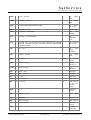
Table Of Contents ................................................................................................................................. 1
1 Introduction ........................................................................................................................................ 4
2 Safety Instructions .............................................................................................................................. 6
3 The sat-nms ACU-RMU .................................................................................................................... 6
3.1 Frontpanel Keyboard .................................................................................................................... 9
3.2 Frontpanel Display ....................................................................................................................... 9
3.3 Frequency Inverters, Motor Controller ........................................................................................... 9
3.3.1 Display and function of the buttons .......................................................................................... 9
3.3.2 Changing Parameters of the Frequency Inverter ..................................................................... 11
3.3.3 Parameter settings in delivery state ....................................................................................... 12
3.3.4 Fault states overview ............................................................................................................ 14
3.4 Circuit breakers .......................................................................................................................... 19
3.5 Contactor ................................................................................................................................... 19
3.6 Power supplies ........................................................................................................................... 19
3.7 sat-nms ACU-ODM ................................................................................................................... 19
3.8 Solid State Relais ....................................................................................................................... 19
3.9 Rear Panel ................................................................................................................................. 19
4 Installation ....................................................................................................................................... 19
4.1 Mechanical installation ............................................................................................................... 20
4.2 Interfaces to the Antenna, Pin descriptions .................................................................................. 20
4.2.1 Connector Layout ................................................................................................................. 20
4.2.2 Pin descriptions .................................................................................................................... 20
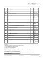
4.3 Start-up ...................................................................................................................................... 26
4.3.1 Setting the IP Address .......................................................................................................... 27
4.3.2 Limit switches ...................................................................................................................... 28
4.3.3 Angle detectors .................................................................................................................... 29
4.3.4 Motors ................................................................................................................................. 29
4.3.5 Pointing/ Tracking ................................................................................................................ 29
4.3.6 Backup of ACU settings ....................................................................................................... 30
5 Operation ......................................................................................................................................... 31
5.1 The Web-based User Interface ................................................................................................... 32
5.2 Antenna Pointing ........................................................................................................................ 33
5.3 Target Memory .......................................................................................................................... 34
5.4 Tracking Parameters ................................................................................................................... 35
5.5 Test Page ................................................................................................................................... 38
5.6 Setup ......................................................................................................................................... 40
5.7 Handheld Terminal ..................................................................................................................... 46
6 Frontpanel operation ......................................................................................................................... 48
6.1 Display mode ............................................................................................................................. 49
6.2 The main menu ........................................................................................................................... 49
6.3 Select targets ............................................................................................................................. 50
6.4 Step move .................................................................................................................................. 50
6.5 Editing Numeric Parameters ....................................................................................................... 50
(C) 2013, SatService GmbH
www.satnms.com
ACU-RMU-UM-1301 Page 1/79
SatService
Gesellschaft für Kommunikationssysteme mbH
6.6 Set tracking mode ....................................................................................................................... 51
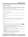
7 Remote Control ................................................................................................................................ 51
7.1 General command syntax ............................................................................................................ 52
7.2 The TCP/IP remote control interface ........................................................................................... 52
7.3 The RS232 remote control interface ............................................................................................ 53
7.4 Parameter list ............................................................................................................................. 54
7.5 One line read via TCP/IP ............................................................................................................ 62
8 Theory of Operation ......................................................................................................................... 63
8.1 Angle Measurement ................................................................................................................... 64
8.2 Pointing / Motor Control .............................................................................................................. 65
8.3 Steptrack .................................................................................................................................... 66
8.3.1 The sat-nms Steptrack Algorithm .......................................................................................... 66
8.3.2 ACU and Beacon Receiver ................................................................................................... 67
8.3.3 Smoothing ............................................................................................................................ 68
8.3.4 Steptrack Parameters ............................................................................................................ 69
8.4 Adaptive Tracking ...................................................................................................................... 71
8.4.1 The sat-nms Adaptive Tracking Algorithm ............................................................................. 71
8.4.2 The Tracking Memory .......................................................................................................... 73
8.4.3 Adaptive Tracking Parameters .............................................................................................. 75
8.5 Program Tracking ....................................................................................................................... 76
8.5.1 Practical Usage .................................................................................................................... 76
8.5.2 File Format .......................................................................................................................... 76
8.6 Faults and Tracking .................................................................................................................... 77
9 Specifications ................................................................................................................................... 78
(C) 2013, SatService GmbH
www.satnms.com
ACU-RMU-UM-1301 Page 2/79
SatService
Gesellschaft für Kommunikationssysteme mbH
(C) 2013, SatService GmbH
www.satnms.com
ACU-RMU-UM-1301 Page 3/79
SatService
Gesellschaft für Kommunikationssysteme mbH
1 Introduction
T h e sat-nms Antenna Control Unit is an antenna controller / positioner with optional satellite tracking
support. It may be operated as a standalone unit or in conjunction of the sat-nms ACU-IDU, a PC based
indoor unit which offers extended tracking capabilities and a full featured visualization interface.
The sat-nms-ACU is available as:
sat-nms ACU-ODM: only the core-module integrated in a compact case prepared for mounting on a
35mm DIN rail
sat-nms-ACU-ODU: complete antenna controller system for AC- or DC-Motors integrated in an
outdoor cabinet that could be mounted directly to the antenna. By mounting a sat-nms LBRX beacon
receiver into this cabinet, you have a complete antenna tracking system in a compact cabinet directly
at your antenna.
sat-nms-ACU-RMU: complete antenna controller system for AC-Motors integrated in a 6RU 19inch
rack mount case for indoor use
sat-nms-ACU19: complete antenna controller system for DC-Motors integrated in a 1RU 19inch rack
mount case for indoor use
For detailed description please refer to the sat-nms documentation CD or www.satnms.com/doc
Main benefits of the sat-nms ACU are:
The ACU outdoor unit is able to act as a standalone antenna control and tracking system without an
indoor unit required.
The ACU provides an Ethernet interface using the TCP/IP and HTTP Internet protocols. It can be
controlled using any PC providing an Ethernet interface and a web browser like the Microsoft Internet
Explorer. The ACU runs a web server which acts as a user interface to the antenna controller.
The ACU is prepared to read the receive level of a sat-nms beacon receiver through the TCP/IP
interface.
The flexible interface design of the ACU enables it to control most types of motor driving antennas for
geostationary satellites.
Supported motor controllers are (configurable in the field):
Power relays: This simple solution is suitable for antennas using 2-speed AC motors.
Frequency inverters: Speed and acceleration ramps are programmed into the inverter module with this
solution.
Servo controllers: Used for DC motors at small antennas.
Supported position sensors are (separate hardware interface modules for each axis:
Resolver Interface: The resolver interface module contains a resolver to digital chip which does the
decoding of the resolver sin/cos signals.
SSI Interface: SSI is a high speed serial interface used by modern digital position encoders.
DC Voltage Interface: The third position encoder interface module contains an A/D converter which
is suited to measure the DC voltages produced by simple inductive angle encoders. This application is
for small antennas especially in the SNG business.
The paragraphs below give a short overview to the contents of the documentation. A subset of this
documentation is stored on the device itself, the complete documentation is available on the sat-nms
documentation CD and at www.satnms.com.
Safety Instructions: This chapter gives an overview about the safety precautions that have to be
(C) 2013, SatService GmbH
www.satnms.com
ACU-RMU-UM-1301 Page 4/79
SatService
Gesellschaft für Kommunikationssysteme mbH
observed during installation, operation and maintenance.
Unit Overview: The installation chapter gives informations about the different modules that are
integrated in the ACU (not ACU-ODM and ACU19).
Installation/Start-up: The installation chapter guides through the installation and setup of the ACU
outdoor module. It describes the mechanical concept of the ACU and the assignment of the ACU's
connectors. It gives you informations about the starting up procedure. Finally you learn in this chapter
how to set the ACU's IP address, which is a essential precondition to operate the ACU by means of a
web browser.
Operation: The sat-nms ACU is operated using a standard
MS Windows based computers. The user interface design
Operating the ACU is mostly self-explanatory. Nevertheless,
web pages which make up the ACU user interface and
alterable parameter.
web browser like the Internet-Explorer on
is straight forward and clearly structured.
the 'Operation' chapter outlines the map of
elaborately describe the meaning of each
Frontpanel Operation : The sat-nms ACU19 and the sat-nms ACU-RMU optionally are equipped with
a frontpanel Human-Machine-Interface. This chapter describes how to use this interface.
Remote Control: The ACU outdoor module provides a versatile remote control interface. A monitoring
& control software may fully operate the ACU either through a TCP/IP network connection or through
the RS232 interface of the ACU. This chapter describes the communication protocol used for remote
control and lists all parameters accessible through the remote interface.
Theory of Operation : This chapter gives a short overview how the ACU works. It also describes the
different tracking algorithms and their parameters. The interaction with a beacon receiver is described
as well. Knowing about the theory regarding this functions helps to find the best parameter settings for
a given application.
Specifications: At the end of the document, the specifications applicable to the sat-nms ACU are
summarized in this chapter.
Support and Assistance
If you need any assistance regarding our ACU, don't hesitate to contact us. We would be pleased to help
you by answering your questions.
SatService GmbH phone +49 7738 9700-3 or -4
Hardstrasse 9
fax +49 7738 97005
78256 Steisslingen www.satnms.com
- Germany Version 4.3 / 2012-11-08
%%
(C) 2013, SatService GmbH
www.satnms.com
ACU-RMU-UM-1301 Page 5/79
SatService
Gesellschaft für Kommunikationssysteme mbH
2 Safety Instructions
Safety
The mains shall only be connected provided with a protective earth wire. Any interruption of the protective
wire, inside or outside the sat-nms ACU, is likely to make the unit dangerous. Intentional interruption is
prohibited.
The unit described in this manual is designed to be used by properly-trained personnel only.
Adjustment, maintenance and repair of the exposed equipment shall be carried out only by qualified
personnel who are aware of hazards involved.
Refer servicing to qualified personnel.
To prevent electrical shock, do not remove covers.
For the correct and safe use of the instrument, it is essential that both operating and servicing personnel
follow generally accepted safety procedures in addition to the safety precautions specified in this manual.
Whenever it is likely that safety protection is impaired, the unit must be made in-operative and secured
against unintended operation. The appropriate servicing authority must be informed. For example, safety is
likely to be impaired if the unit fails to perform the intended measurements or shows visible damage.
Ensure that the cabinet is proper connected to the protective earth conductor.
The circuit breaker, that fuses the mains for the sat-nms ACU has to switch off all phases AND the neutral
wire as well.
WARNINGS
The outside of the equipment may be cleaned using a lightly dampened cloth. Do not use any cleaning
liquids containing alcohol, methylated spirit or ammonia etc.
Follow standard Electrostatic Discharge (ESD) procedures when handling the Unit.
Apply the appropriate voltage according to the attached schematic.
In case of switching off all the circuit breakers is still voltage available at the mains terminals!
Only use shielded cable to connect the AZ- and EL-Motor. The other components in the cabinet might
be jammed through the harmonic waves the frequency inverters inject into the motor wires.
Use only double shielded twisted pair cables (e.g. CAT7 Ethernet cable) to connect the resolvers to the
sat-nms ACU
Only ACU-ODU: If the Unit is equipped with an optional air ventilation, avoid direct contact with jets
of water, normal rain is no problem.
(C) 2013, SatService GmbH
www.satnms.com
ACU-RMU-UM-1301 Page 6/79
SatService
Gesellschaft für Kommunikationssysteme mbH
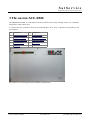
3 The sat-nms ACU-RMU
The sat-nms ACU-RMU is a full featured antenna positioner and antenna tracking system. It is completely
integrated to a 6RU 19inch case.
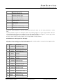
It consists from the components listed in the following table. All of these components are described in the
next chapters.
No. component
No. component
1
Frontpanel Keyboard
6
Power Supplies
2
Frontpanel Display
7
sat-nms ACU-ODM
3
Frequency Inverters
8
Solid State Relays
4
Circuit Breakers
9
Rear Panel
5
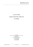
Contactor
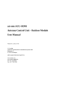
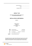
Front panel view (with integrated optional display and keyboard)
(C) 2013, SatService GmbH
www.satnms.com
ACU-RMU-UM-1301 Page 7/79
SatService
Gesellschaft für Kommunikationssysteme mbH
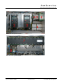
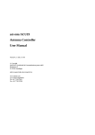
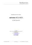
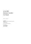
Front view with opened fronpanel
Rear view with opened rearpanel
(C) 2013, SatService GmbH
www.satnms.com
ACU-RMU-UM-1301 Page 8/79
SatService
Gesellschaft für Kommunikationssysteme mbH
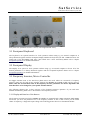
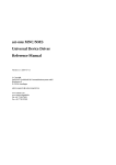
Rear panel view (standard connector version, with integrated POL-drive)
3.1 Frontpanel Keyboard
The keyboard is an optional interface for local operation without using e.g. an external computer. It is
always delivered together with the Frontpanel display. Besides the keyboard you find 3 LEDs that show the
actual state of the ACU-RMU (fault state / limit switch state / motor movement) Please refer to chapter
Frontpanel Operation for detailed informations.
3.2 Frontpanel Display
The Display is an option for local operation without using e.g. an external computer. It shows all of the
desired parameters. It is always delivered together with the frontpanel keyboard. Please refer to chapter
Frontpanel Operation for detailed informations.
3.3 Frequency Inverters, Motor Controller
For bigger antennas most of the time three phase motors are used. These are connected to frequency
inverters which are the high power interface between the sat-nms ACU-ODM module and the motors.
Please take into account that some of the frequency inverter parameters are motor dependent and
that these have to be changed to your specific antenna motors.
The following chapters give a short overview of the frequency-inverters operation. If you need more
detailed informations, please refer to the manual of the frequency inverters.
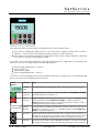
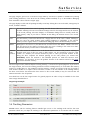
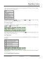
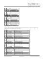
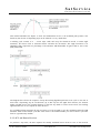
3.3.1 Display and function of the buttons
The frequency inverters used in the sat-nms ACU-RMU are equipped with a Basic Operation Panel (BOP)
that shows you all of the parameters set to the frequency inverter. It also is able to show you the actual
values of frequency, voltage and output voltage. The following picture shows how the BOP looks like:
(C) 2013, SatService GmbH
www.satnms.com
ACU-RMU-UM-1301 Page 9/79
SatService
Gesellschaft für Kommunikationssysteme mbH
After start-up of the inverter the display of the BOP shows you the following values:
If the motor is running, the display shows you the actual motor frequency and the direction (with or
without a - as prefix of the shown frequency what represents the rotation-direction)
If the motor is not running, the display is alternating between the pre- selected frequency with prefix
for the direction and the actual frequency 0.00Hz.
If you like to get some other parameters, press and hold the button Fn longer than 2s. By pressing the
button Fn once you can change between the following parameters:
DC link voltage (indicated by d - units V).
output current. (A)
output frequency (Hz)
output voltage (indicated by o - units V)
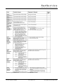
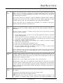
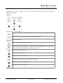
To return to the start-up display mode, press and hold the button Fn for longer than 2s. The following Table
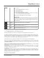
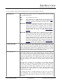
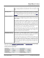
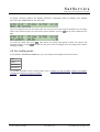
shows the function of the frequency-inverters buttons.
Panel/
Button.
Function
Effect.
indicates
status
The LCD displays the settings and values currently used by the converter.
start
converter
pressing the button starts the converter. This button is disabled by default.
To enable this button set P0700 = 1.
stop
converter
OFF1 Pressing the button causes the motor to come to a standstill at the
selected ramp down rate. Disabled by default, to enable set P0700 =1.
OFF2 Pressing the button twice (or once long) causes the motor to coast to
a standstill. This function is always enabled.
change
direction
press this button to change the direction of rotation of the motor. Reverse is
indicated by a minus (-) sign or a flashing decimal point. Disabled by
default, to enable set P0700 = 1.
jog motor
Pressing this button while the inverter has no output causes the motor to
start and run at the preset jog frequency. The motor stops when the button
is released. Pressing this button when the motor is running has no effect.
functions
this button can be used to view additional information. It works by pressing
and holding the button. It shows the following, starting from any parameter
(C) 2013, SatService GmbH
www.satnms.com
ACU-RMU-UM-1301 Page 10/79
SatService
Gesellschaft für Kommunikationssysteme mbH
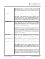
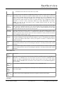
during operation:
1.
2.
3.
4.
5.
DC link voltage (indicated by d - units V).
output current. (A)
output frequency (Hz)
output voltage (indicated by o - units V).
The value selected in P0005 (If P0005 is set to show any of the above
(3, 4, or 5) then this will not be shown again).
Additional presses will toggle around the above displays.
Jump Function
From any parameter (rXXXX or PXXXX) a short press of the Fn button
will immediately jump to r0000, you can then change another parameter, if
required. Upon returning to r0000, pressing the Fn button will return you to
your starting point.
access
pressing this button allows access to the parameters
parameters
increase
value
pressing this button increases the displayed value. To change the Frequency
Setpoint via the BOP set P1000 = 1.
decrease
value
pressing this button decreases the displayed value. To change the Frequency
Setpoint via the BOP set P1000 = 1.
Table 1 origin: Siemens user Documentation 6SE6400-5AA00-0BP0
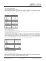
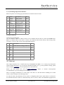
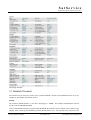
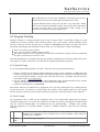
3.3.2 Changing Parameters of the Frequency Inverter
On Table 4 and Table 5 you can see the test-settings that are programmed in the delivery state.
To change the parameters press button P once, now you can change the parameter-number with the arrowbuttons up and down. To change the chosen parameter press button P once again. Now you can change the
parameter with the arrow-buttons to the desired value. To save the new parameter value, press button P
once. To go back to the parameter choice, without saving, press button Fn.
The Parameters that you can find in row Value 1 have to be set as written in the following tables.
When you are finished with setting the parameters, you have to set parameter 971 to value 1 (transfer Data
from RAM to EEPROM) and press button P. Otherwise the settings are deleted with the next power-down
of the frequency inverter.
When you have changed the parameters in quick commissioning mode (Parameter No. 10 = 1), the changed
parameters have to be saved with setting Parameter No. 3900 = 3.
ATTENTION! If you save the quick commissioning changes with Parameter No. 3900 = 1, all of the
interface parameters are set to factory defaults, and have to bet set to the desired values for the sat-nms
ACU-RMU to ensure proper function.
ATTENTION! Change the frequency inverters motor-parameters only when the corresponding motor is
connected. This is because while changing the motor parameters the frequency inverter makes some
measures to define the power that is needed to make the motor run. In normal cases it suffices to change the
following Parameters of the frequency-inverters:
Setting of the motor parameters
(C) 2013, SatService GmbH
www.satnms.com
ACU-RMU-UM-1301 Page 11/79
SatService
Gesellschaft für Kommunikationssysteme mbH
Table 2
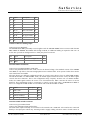
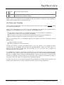
Setting of the interface parameters
Table 3
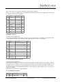
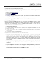
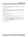
3.3.3 Parameter settings in delivery state
Setting of the motor parameters in delivery state
(C) 2013, SatService GmbH
www.satnms.com
ACU-RMU-UM-1301 Page 12/79
SatService
Gesellschaft für Kommunikationssysteme mbH
Table 4
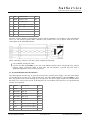
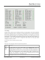
Setting of the interface parameters in delivery state
(C) 2013, SatService GmbH
www.satnms.com
ACU-RMU-UM-1301 Page 13/79
SatService
Gesellschaft für Kommunikationssysteme mbH
Table 5
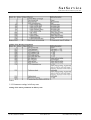
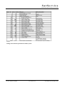
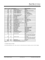
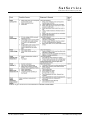
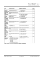
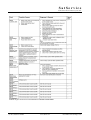
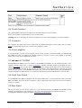
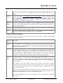
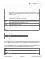
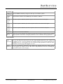
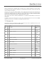
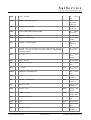
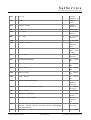
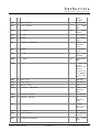
3.3.4 Fault states overview
The following tables give you a short overview over the fault states, the frequency inverter is able to display.
(C) 2013, SatService GmbH
www.satnms.com
ACU-RMU-UM-1301 Page 14/79
SatService
Gesellschaft für Kommunikationssysteme mbH
Table 6 origin: Siemens user Documentation 6SE6400-5AA00-0BP0
(C) 2013, SatService GmbH
www.satnms.com
ACU-RMU-UM-1301 Page 15/79
SatService
Gesellschaft für Kommunikationssysteme mbH
Table 7 origin: Siemens user Documentation 6SE6400-5AA00-0BP0
(C) 2013, SatService GmbH
www.satnms.com
ACU-RMU-UM-1301 Page 16/79
SatService
Gesellschaft für Kommunikationssysteme mbH
Table 8 origin: Siemens user Documentation 6SE6400-5AA00-0BP0
(C) 2013, SatService GmbH
www.satnms.com
ACU-RMU-UM-1301 Page 17/79
SatService
Gesellschaft für Kommunikationssysteme mbH
Table 9 origin: Siemens user Documentation 6SE6400-5AA00-0BP0
(C) 2013, SatService GmbH
www.satnms.com
ACU-RMU-UM-1301 Page 18/79
SatService
Gesellschaft für Kommunikationssysteme mbH
Table 10 origin: Siemens user Documentation 6SE6400-5AA00-0BP0
3.4 Circuit breakers
The circuit breakers disconnect the mains from the units build to the control cabinet.
Every circuit breaker is labeled with the unit it is connected to.
Warning: In case of switching off all the circuit breakers it is still voltage available at the mains terminals!
3.5 Contactor
The contactor disconnects the motor's mains when the Disable/ Emergency contact (J6)is open. In chapter
4.2.2 you find the description how to connect the emergency switch.
3.6 Power supplies
In the ACU-RMU you find 2 power supplies: one is for the processor of the ACU-ODM, it is labelled with
PS ODM. The other one supplies the external contacts of the ACU e.g. the control signals for the POL
drivers relais. This one is labelled with 'PS EXT'.
3.7 sat-nms ACU-ODM
The sat-nms ACU-ODM is the core module of the sat-nms ACU-RMU. For the detailed operation of the
antenna controller please refer to chapter 5 Operation. Another interesting chapter is belonging the ACUODM is 4.3 Startup here you find also the description how to change the IP address of the unit in order to
integrate the antenna controller in your sub-net. A short version of the documentation could also be found
on the internal website of the sat-nms ACU-RMU. Just enter the IP-address of the unit (standard-IP is:
192.168.2.69) into the Web-browser of a connected computer and press the HELP button on the left side.
3.8 Solid State Relais
If your sat-nms ACU-RMU is equipped with the optional POL-drive, you find solid state relais in your satnms ACU-RMU. The POL Motor is normally a small single phase motor that does not need a frequency
inverter for driving.
3.9 Rear Panel
On the rear panel you find all the connectors of the interfaces between the sat-nms ACU-RMU and the
Antenna. It is designed for easy replacement, all of the connections is done by standard connectors.
A detailed pin-description is given in chapter 4.2 Interfaces to the Antenna
(C) 2013, SatService GmbH
www.satnms.com
ACU-RMU-UM-1301 Page 19/79
SatService
Gesellschaft für Kommunikationssysteme mbH
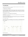
4 Installation
The following chapter describes how to install the ACU-RMU mechanically and electrically. Additional a
detailed start-up procedure is given in this chapter.
4.1 Mechanical installation
T he sat-nms ACU-RMU is completely integrated into a 6RU 19inch case with standard mounting holes.
The case of the sat-nms ACU-RMU is not strong enough to carry the complete unit only on the front
mounting holes! Because of that, take care that the sat-nms ACU-RMU is placed onto a bar guide that
carries the complete weight of the sat-nms ACU-RMU. The screws have to be fixed properly to keep the
sat-nms ACU-RMU in its position.
4.2 Interfaces to the Antenna, Pin descriptions
ATTENTION! Electrical installation shall be carried out only by qualified personnel who are instructed and
aware of hazards of electrical shocks.
All connectors of the sat-nms ACU-RMU are located at the rear side of the case. The following chapters
show the standard pin configuration. If you have a non-standard version, please refer to the documentation
enhancement that shows the pin descriptions of it.
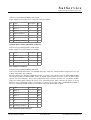
4.2.1 Connector Layout
Below the connector layout of the ACU-RMU is shown. The connector type is described together with the
corresponding pin description in the following chapter. The given connector type says which connector you
need on your cable!
4.2.2 Pin descriptions
J1 Three-phase current Mains Connector
(C) 2013, SatService GmbH
www.satnms.com
ACU-RMU-UM-1301 Page 20/79
SatService
Gesellschaft für Kommunikationssysteme mbH
Connector Type: Harting HAN B 6+PE female
Power supply for the motors to be connected to the ACU-RMU
pin signal
description type
1
Phase 1
IN
2
Phase 2
IN
3
Phase 3
IN
4
neutral conductor
IN
5
n.c.
6
n.c.
PE
grounding conductor
J2 Single-phase current UPS Mains Connector
Connector Type: Harting HAN A 3+PE female
Power supply for the ACU-RMU core module.
pin signal
description type
1
Phase
IN
2
neutral conductor
IN
3
n.c.
IN
PE
grounding conductor
J3-1 AZ Motor Connector
Connector Type: Harting HAN B 6+PE male
Connect the azimuth motor here. Use shielded cable only. Take care, that the shield is connected to J3-1 and
is NOT connected to the crankcase.
The ACU knows two different configuration modes to control a motor driver. They are called 'DIR-START'
and 'DUAL-START'. In 'DIR-START' mode, the 'FWD' signal switches the motor on/off, the 'REV' signal
controls the motor direction. This is the configuration many frequency inverters use. In 'DUAL-START'
mode, the 'FWD' signal switches the motor on in forward direction, 'REV' activates the motor in reverse
direction. This configuration mode is convenient to control a motor with relays. At sat-nms ACU-RMU it
has to be configured as DIR-START for AZ and EL and as DUAL-START for POL.
pin signal
description type
1
Phase 1
OUT
2
Phase 2
OUT
3
Phase 3
OUT
4
n.c.
5
n.c.
6
n.c.
PE
grounding conductor
J3-2 AZ Limit Switch Connector
(C) 2013, SatService GmbH
www.satnms.com
ACU-RMU-UM-1301 Page 21/79
SatService
Gesellschaft für Kommunikationssysteme mbH
Connector Type: D-Sub9 female
Connect the azimuth limit switches here.
The limit switch inputs internally are connected to the external 24V / GND rails. The switches are connected
directly to the input pairs without any external ground or supply cabling. The ACU treats a closed contact as
OK, contacts have to be opened to indicate the 'limit reached' condition.
Please note, that the left/right azimuth and polarization limit switches have to be swapped when the antenna
is operated at the southern hemisphere.
pin signal
1
n.c.
2
n.c.
3
n.c.
4
n.c.
5
AZ Lo
6
GND_Ext
7
AZ Hi
8
GND_EXT
9
n.c.
description
type
CCW Limit IN
CW Limit
IN
J4-1 EL Motor Connector
Connector Type: Harting HAN B 6+PE male
Connect the elevation motor here. Use shielded cable only. Take care, that the shield is connected to J4-1
and is NOT connected to the crankcase.
The ACU knows two different configuration modes to control a motor driver. They are called 'DIR-START'
and 'DUAL-START'. In 'DIR-START' mode, the 'FWD' signal switches the motor on/off, the 'REV' signal
controls the motor direction. This is the configuration many frequency inverters use. In 'DUAL-START'
mode, the 'FWD' signal switches the motor on in forward direction, 'REV' activates the motor in reverse
direction. This configuration mode is convenient to control a motor with relays. At sat-nms ACU-RMU it
has to be configured as DIR-START for AZ and EL and as DUAL-START for POL.
pin signal
description type
1
n.c.
2
n.c.
3
n.c.
4
Phase 1
OUT
5
Phase 2
OUT
6
Phase 3
OUT
PE
grounding conductor
J4-2 EL Limit Switch Connector
Connector Type: D-Sub9 female
Connect the elevation limit switches here.
The limit switch inputs internally are connected to the external 24V / GND rails. The switches are connected
directly to the input pairs without any external ground or supply cabling. The ACU treats a closed contact as
OK, contacts have to be opened to indicate the 'limit reached' condition.
(C) 2013, SatService GmbH
www.satnms.com
ACU-RMU-UM-1301 Page 22/79
SatService
Gesellschaft für Kommunikationssysteme mbH
pin signal
1
n.c.
2
n.c.
3
n.c.
4
n.c.
5
EL Lo
6
GND_Ext
7
EL Hi
8
GND_EXT
9
n.c.
description
type
EL Lower Limit IN
EL Upper Limit IN
J5 Beacon Receiver Analog Input
Connector Type: SMA male
The sat-nms ACU-RMU preferably is used together with the sat-nms LBRX beacon receiver. With the satnms LBRX the sat-nms ACU-RMU talks though TCP/IP, no additional cabling is required in this case. At
J5 the ACU provides an analog interface to third party beacon receivers.
pin
signal
description
type
Pin
Beacon Level beacon level signal 0..10V IN
case GND
J5-1 POL Motor Connector
Connector Type: Harting HAN A 3+PE male
Connect the polarisation motor here. Take care for the desired voltage. The standard version of the sat-nms
ACU-RMU is only able to drive 230V single phase motors without brake. As an option a brake driver and/or
110V transformer is available.
The ACU knows two different configuration modes to control a motor driver. They are called 'DIR-START'
and 'DUAL-START'. In 'DIR-START' mode, the 'FWD' signal switches the motor on/off, the 'REV' signal
controls the motor direction. This is the configuration many frequency inverters use. In 'DUAL-START'
mode, the 'FWD' signal switches the motor on in forward direction, 'REV' activates the motor in reverse
direction. This configuration mode is convenient to control a motor with relays. At sat-nms ACU-RMU it
has to be configured as DIR-START for AZ and EL and as DUAL-START for POL.
pin signal
description type
1
POL CCW
OUT
2
POL CW
OUT
3
neutral conductor
OUT
PE
grounding conductor
J5-2 POL Limit Switch Connector
Connector Type: D-Sub9 female
Connect the polarization limit switches here.
The limit switch inputs internally are connected to the external 24V / GND rails. The switches are connected
directly to the input pairs without any external ground or supply cabling. The ACU treats a closed contact as
(C) 2013, SatService GmbH
www.satnms.com
ACU-RMU-UM-1301 Page 23/79
SatService
Gesellschaft für Kommunikationssysteme mbH
OK, contacts have to be opened to indicate the 'limit reached' condition.
Please note, that the left/right azimuth and polarization limit switches have to be swapped when the antenna
is operated at the southern hemisphere.
pin signal
description
1
n.c.
2
n.c.
3
n.c.
4
n.c.
5
POL Lo
6
GND_Ext
7
POL Hi
8
GND_EXT
9
n.c.
type
CCW Limit IN
CW Limit
IN
J6 Disable Connector
Connector Type: D-Sub9 male
If you have an emergency stop button, connect it here. If you do not have one, make a bridge between Pin
1 and 8 and between Pin 2 and 9. Without these bridges the motors mains are interrupted.
pin signal
description
type
1
K1-
disable contactor input - IN
2
K1+
disable contactor input + IN
3
n.c.
4
n.c.
5
n.c.
6
n.c.
7
n.c.
8
GND_EXT
OUT
9
24V_EXT
OUT
J7, J8, J9 Angle Encoder Connector
Connector Type: D-Sub9 male
The sat-nms ACU-RMU is available in different configurations of angle encoders. It is possible to equip it
with interfaces for standard resolvers, for optical SSI encoders or for analog sensors (potentiometers). It is
possible to mix it (e.g. SSI encoder at AZ and EL and an analog sensor for POL). You have to select type of
interface when you order the sat-nms ACU-RMU. A label nearby the angle connectors show which type of
interface is installed.
Find below the pin description of all possibilities:
J7, J8, J9 Resolver Interface
pin signal description
type
1
IN
GND
resolver SIN
(C) 2013, SatService GmbH
www.satnms.com
ACU-RMU-UM-1301 Page 24/79
SatService
Gesellschaft für Kommunikationssysteme mbH
2
SIN
resolver SIN
IN
3
GND
resolver COS
IN
4
COS
resolver COS
IN
5
GND
drive signal to resolver OUT
6
REF
drive signal to resolver OUT
7
n.c.
8
n.c.
9
n.c.
The ACU resolver interface is designed for resolvers with an impedance of 100 Ohms or more and transfer
factor 0.5. The interface applies 4Veff / 2000Hz to the resolver drive coil. It expects 2Veff at the sine /
cosine inputs at the maximum positions.
When connecting a resolver to the ACU, please consider the following:
Use a shielded, twisted pair cable.
Connect the cable shield either to the case of the DSub9 connector or to the ground at the resolver
housing. Never connect the shield at both ends, this will introduce a ground loop and cause a
significant degradation of the resolver's accuracy.
J7, J8, J9 SSI Position Encoder Interface
The SSI positional encoder may be powered from the ACU internal power supply. +5V and +24V clamps
are provided at the connector. To avoid ground loops, the cable shield should be connected either to pin 1
or to the ground at the encoder housing, never at both ends. The power supply outputs are internally fused.
Be aware not to cause a short circuit. If this happens, the core module of the unit has to be opened and the
fuse has to be replaced.
pin signal
description
type
1
GND
2
SSI-Data+ SSI data
IN
3
SSI-Data-
IN
4
SSI CLK+ SSI clock
OUT
5
SSI CLK- SSI clock
OUT
6
n.c.
7
+5V
encoder power supply
8
+24V
encoder power supply
9
n.c.
SSI data
(C) 2013, SatService GmbH
www.satnms.com
ACU-RMU-UM-1301 Page 25/79
SatService
Gesellschaft für Kommunikationssysteme mbH
J7, J8, J9 Analog Angle Sensor Interface
Below the pinout of an analog type positional sensor interface board is shown.
pin signal
description
type
1
AGND
analog ground
OUT
2
INPUT
A/D converter input IN
3
REF
reference voltage
OUT
4
AGND
analog ground
OUT
5
+15V (opt) optional DC out
OUT
6
-15V (opt) optional DC out
OUT
7
+9V (opt)
optional DC out
OUT
8
GND
digital ground
OUT
9
n.c.
J11 LAN Connector
Connector Type: RJ45 male
J11 is the Ethernet 10Base-T / RJ45 connector. Use a standard network cable to connect the sat-nms ACURMU to an Ethernet hub. If you want to connect your computer and the ACU directly without using a hub,
you need a crossover cable for this with swapped RX/TX lines.
pin signal description
type
1
TX+
default Ethernet cabling (10Base-T) OUT
2
TX-
OUT
3
RX+
IN
RX-
IN
4
5
6
7
8
4.3 Start-up
This chapter describes how to install and set-up the sat-nms ACU-RMU. It is a step-by-step description
without detailed description. If you need more detailed description for e.g. some parameter settings, please
refer to chapter 5 Operation, all of the parameters are described here.
Before you start, please first read the Safety Instructions chapter. It contains some important
recommendations to prevent damage from the ACU.
Then, we strongly recommend to do a first setup of the ACU on a lab desk before installing it at it's final
location. This is mainly for the following reason:
To setup the ACU's IP parameters, the PC used for configuring and the ACU must either be connected to
the same Ethernet hub or must be connected directly with a crossover cable. The initialization program does
(C) 2013, SatService GmbH
www.satnms.com
ACU-RMU-UM-1301 Page 26/79
SatService
Gesellschaft für Kommunikationssysteme mbH
not work through routers or intelligent network switches.
Hence, the typical sequence of tasks when putting an sat-nms ACU outdoor module into operation is as
follows:
1.
2.
3.
4.
Read the chapter Safety Instructions.
Set the ACU's IP address.
Mechanically mount the ACU.
Connect the ACU to the antenna (position encoders, limit switches and motor drivers). Finally connect
the UPS power supply and the Ethernet network.
5. Start up the system and set the parameters as described below.
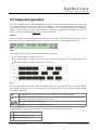
6. As last step connect the power supply of the motors and start them up as described below.
4.3.1 Setting the IP Address
Before you can operate the sat-nms ACU-RMU, you need to set the ACU's IP address. There is a special
configuration program on the documentation CD shipping with the ACU for this purpose. We recommend to
configure the ACU's TCP/IP settings before you install the sat-nms ACU-RMU at it's final place. To
configure the ACU, the following equipment is required:
The sat-nms ACU-RMU itself.
230V AC power at connector J2.
A Computer running a Microsoft Windows operating system equipped with CD-ROM drive and
Ethernet network card.
A CAT5 crossover network cable or an Ethernet hub and standard network cables to connect the ACU
and the computer.
The CD-ROM shipping with the sat-nms ACU.
Setting the ACU's IP parameters now is easily done within a few minutes.
1. First install a network cable between the ACU and your computer. If you have a crossover cable
available, this is very easy: simply put the cable into the network connectors of computer and ACU.
Without a crossover cable, you need to connect both, the computer and the ACU to the same network
hub using two standard network cables. It is essential, that the computer and the ACU are connected
to the same network segment, the configuration program is not able to find the ACU through routers or
network switches.
2. Now power on your computer and connect the ACU to the 230V AC supply (J2). Take care, that
circuit breaker F3 inside the sat-nms ACU-RMU is switched to on state, the other ones have to be
switched off.
3. Insert the CD-ROM into the computer's drive and inspect it's contents through the 'My Computer' icon
on your desktop. Double-click to the 'ChipTool.exe' program in the 'ChipTool' directory.
4. When the ChipTool program is running, the program shows a list containing at least one entry
describing the actual network parameters of the sat-nms ACU-RMU.
(C) 2013, SatService GmbH
www.satnms.com
ACU-RMU-UM-1301 Page 27/79
SatService
Gesellschaft für Kommunikationssysteme mbH
5. The serial number of the core module shown in the first column of the list. If the list stays empty, the
ACU is not connected properly. If there are more entries in the list, the configuration program has
found other devices in this network segment which use the same technology.
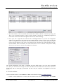
6. Now open with a right-click the sub-menu IP configuration to open the IP configuration
window of the program. In this form the ACU's MAC address is shown on top, below you find the
fields to configure the new IP address and network mask. If the ACU later shall be operated through a
router, enter the address of the router on the gateway field, otherwise leave this field blanc. Be sure,
that the 'DHCP' mark is unchecked, the other values have to be set as shown on the picture. Finally
click to the 'Yes' button to set the new parameters at the ACU.
Now the IP configuration of the ACU is completed. You may finally want to test if the ACU is reachable
now. Start your web browser and type the ACU's IP address into the URL field of the browser. The ACU
should reply with it's main page, provided that the ACU and your computer are configured for the same
subnet.
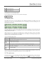
4.3.2 Limit switches
Connect the limit switches to the sat-nms ACU-RMU as described in chapter 4.2.2 Pin description .
1. Switch on circuit breaker F3 to on state, take care, that the other ones are in off-position. The sat-nms
(C) 2013, SatService GmbH
www.satnms.com
ACU-RMU-UM-1301 Page 28/79
SatService
Gesellschaft für Kommunikationssysteme mbH
ACU-RMU should be reachable via Ethernet now.
2. Check the function and correlation of all limit-switches manually. On the sat-nms ACU-RMUs mainwebsite a limit fault is shown as soon it occurs. On the test-page every single limit switch is displayed.
For more detailed informations see chapter 5 Operation
4.3.3 Angle detectors
Connect the angle detectors to the sat-nms ACU-RMU as described in chapter 4.2.2 Pin description .
1. Configure the desired type of detector on the setup-page.
2. Set the soft-limits to the expected values (at first it is ok if you do this approximately, later on you
need to type in here the exact values).
3. Check the rotational direction of the resolvers. If possible, do this by turning the resolver axis directly,
otherwise you have to move the antenna by hand. Maybe you have to invert the rotational direction on
the setup page.
4. Set the offset of the angle detectors to the desired values by using the calc. function.
If you need more detailed information, please refer to chapter 5.6 Setup.
4.3.4 Motors
Before you connect the motors to the sat-nms ACU-RMU, take care that the circuit breakers F1, F2 and if
available F4 are in off position before connecting the motors.
1. Connect the motors to the sat-nms ACU-RMU as described in chapter 4.2.2.
2. Connect the emergency stop button to J6. If you do not have one, take care that Pin 1 and 8 as well as
Pin 2 and 9 are bridged. Without a connection between these pins the power supply of the motors is
disabled.
3. Press the STOP button on the sat-nms ACU-RMUs website. By this you can be shure that no motor
movement will occur by switching on the circuit breakers.
4. Turn on circuit breaker F1 and F2, the frequency inverters have to run now.
5. Set the motor parameters to the frequency inverters as written in chapter 3.3.2 to the desired values.
6. Check the motor rotating directions, if necessary change it by interchanging 2 phase-wires of the motor
cable.
7. If available, turn on F4 now and check the rotational direction of the POL Motor. If necessary, change
pin 1 and 2 at J5.1 to reverse the direction.
8. Drive the antenna in every direction (AZ, EL and POL) until the limit switches stop the motor
movement to ensure that the limit switches work well.
ATTENTION! While doing this test it is absolutely necessary to be very mindful to check, if nothing
collides!
9. Set the soft-limits to the desired values (e.g. 1° before the hardware limit switch is activated)
If you need more detailed informations about the frequency inverters (parameter settings, fault states etc.),
please refer to chapter 3.3 Frequency Inverters.
4.3.5 Pointing/ Tracking
Now, the setup of all interfaces to the antenna is done. By this everything is prepared to configure the ACURMU to the desired operation mode, to save targets and finally to set the sat-nms ACU-RMU into service.
In chapter 5 Operation you find a detailed description of the pointing and tracking parameters.
To use the function pointing by stating an orbit position you have to configure the 'Location' parameters on
the setup page to the geodetic location of your antenna. Take care to type in position with enough accuracy
(C) 2013, SatService GmbH
www.satnms.com
ACU-RMU-UM-1301 Page 29/79
SatService
Gesellschaft für Kommunikationssysteme mbH
(0.001°). For further informations, please refer to chapter 5.6 Setup for location parameters and 5.3 Target
Memory for using this pointing function.
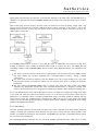
4.3.6 Backup of ACU settings
The last step that is recommended to be done is the backup of ACU settings. By this way an easy
replacement of the ACU-ODM could be performed.
The following step-by step description shows how to do this.
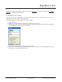
1. Open the chiptool
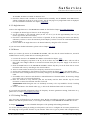
2. Right click to the desired unit. A drop-down list will open, choose FTP
3. A small window like shown on the following picture will be opened. Please double-check the displayed
IP, you might adjust it in the drop-down list here.
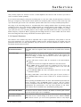
4. Login with username service and password service
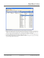
5. Now you see on the right side the file system of the ACU like shown on the following picture. On the
left side you see the computers file system.
(C) 2013, SatService GmbH
www.satnms.com
ACU-RMU-UM-1301 Page 30/79
SatService
Gesellschaft für Kommunikationssysteme mbH
6. Browse on the left side to the desired location to which you like to save the backup
7. Right-click the app.dat file and choose copy in the drop down list. The file will immediately be
copied to the location shown on the left side. If you have saved targets, you might backup them in the
same way. They are named targetXX.txt. XX represents the number of the target.
8. To copy a backup file to the ACU, browse on the left side if the window to the desired app.dat file
and copy this file to the ACU in the same way (right click->copy)
9. After copying an app.dat file to the ACU, you have to reboot the unit (power off). By next starting
up, the new app.dat file will be used.
(C) 2013, SatService GmbH
www.satnms.com
ACU-RMU-UM-1301 Page 31/79
SatService
Gesellschaft für Kommunikationssysteme mbH
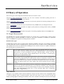
5 Operation
The sat-nms ACU outdoor module is designed to be controlled over a network link using a standard web
browser. This means in practice, that the user interface to the ACU appears in your browser window after
you type in the ACU's IP address in the address field of the browser program.
Operating the ACU is mostly self-explanatory.
5.1 The Web-based User Interface
After having connected the ACU to a power supply and set the ACU's IP address, you can access the
ACU's user interface. To do this, start your favorite web browser program (Internet Explorer, Netscape
Navigator, Opera or what else program you prefer). At the address field, where you normally enter the URL
of a web page you want to see, type in the IP address of the sat-nms ACU you want to control.
The ACU shows a web page consisting of a navigation bar at the left side of the browser window and the
actual antenna pointing in the main part of the window. The readings automatically refresh once a second.
The refresh-rate may be adjusted on the setup-page from software version 2.1.007 or higher.
The navigation bar at the left contains a couple buttons which build the ACU's main menu:
Pointing: This button switches back to the main page you already see when you connect
to the ACU. This page displays the actual antenna pointing together with some status
information. You also use this page to move the antenna to a certain pointing given as
azimuth / elevation values.
Target: By clicking to this button you switch to the 'Target' page where you can store
and recall the antenna pointing for up to eight satellites.
Tracking: sat-nms ACUs with the tracking option installed offer the tracking mode and
tracking fine tune parameters on this page.
Test: By clicking to this button you switch to the 'Test' page. The 'Test' page shows the
low level I/O signals of the ACU. It helps you to install the ACU or to identify a
malfunction of peripheral components.
Setup: This button switches to the 'Setup' page which lets you inspect or change less
common parameters which usually are set only once to adapt the ACU to it's working
environment.
Info: After a mouse click to this button, the ACU outdoor module shows a table with
information like the serial number of the device or the revision ID and compilation date
of the software.
Help: Clicking to this button shows the on-line version of this user manual
Step Move: Clicking to the buttons in this area moves the antenna a small step to the
indicated direction. For azimuth and elevation 'small step' and 'large step' buttons are
provided. A 'small step' is the angle defined with the 'XX step delta' parameters at the
Setup page, a 'large step' is ten times this value. With the polarization axis, steps always
are 1°.
STOP: Clicking to the STOP button immediately stops all motors. The ACU indicates a
fault. A click to the RESET button releases this fault.
(C) 2013, SatService GmbH
www.satnms.com
ACU-RMU-UM-1301 Page 32/79
SatService
Gesellschaft für Kommunikationssysteme mbH
RESET: The RESET button lets the ACU acknowledge any motor diver faults by
activating the reset-circuit to the motor drivers for 800 msec. All faults internally latched
by the ACU are cleared and the target pointing values are set to the values actually read
from the position sensors.
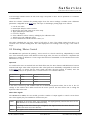
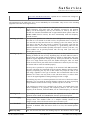
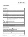
5.2 Antenna Pointing
The 'Pointing' page is the main page of the ACU user interface which shows the actual antenna pointing and
some status information. The 'Pointing' page automatically refreshes once a second. The refresh-rate may be
adjusted on the setup-page from software version 2.1.007 or higher. The table below describes the
information shown by this page:
Parameter
Name
Description
Azimuth
Elevation
Polarization
The bold printed figures show the actual antenna pointing angles as read from the position
sensors. If the polarization axis is not controlled by the ACU, '-.---°' is displayed in the
polarization field.
Xx. target Below the measured angles the ACU displays the target values of the antenna pointing. The
value
target values are the angles which have been commanded to the ACU. You may click to a
target angle in order to change the pointing manually. The ACU display a dialog page where
you can enter the new pointing angle. If you click to the 'SUBMIT' button in this dialog
page, the antenna immediately moves to the new position. To go back to the main page
without changing the pointing, click to the 'Back' button of your Web browser.
Axis
flags
state Below the target values, for each axis there is a field reserved which contains some state
information for this axis. While the motor is running, 'MOVING' is displayed at this place.
If the motor has been stopped due to a fault or an emergency stop request, a red label
'STOPPED' is displayed. Finally, if the ACU recognizes the activation of a limit switch, the
orange colored label 'LIMIT' is displayed in this field.
Target name The name of the satellite the antenna is pointing to. Click to the name to get a dialog page
where you can change the name. The name is stored together with a satellite's pointing at
the target memory page. If you change the target pointing values, the target name is set to
'unknown' by the ACU. Hence you first should adjust the antenna pointing, then enter the
satellite's name.
Tracking
mode
sat-nms ACUs with the tracking option installed display the actual tracking mode / state in
this field. ACUs without tracking show 'OFF' all the time. In STEP and ADAPTIVE
tracking modes this field shows what the tracking actually is doing and some information
about the tracking data in memory:
fill tells how many hours of step track data for calculating a model the ACU actually has
in memory. This data may be used in ADAPTIVE mode to predict the satellite
movement in case of a beacon failure. The smoothing which may be applied to the
step track also relies on this data.
age means the age of the most recent successful tracking step. In other words this
describes how many hours ago the beacon was lost in case of a beacon failure.
Beacon
level
This field shows the beacon level as read from the beacon receiver. Depending on the
source defined at the Setup page, this either is the beacon level reported by a sat-nms
LBRX beacon receiver via TCP/IP of the level derived from the ACU's analog input.
Temperature The actual temperature inside the ACU enclosure. This value is for information only.
(C) 2013, SatService GmbH
www.satnms.com
ACU-RMU-UM-1301 Page 33/79
SatService
Gesellschaft für Kommunikationssysteme mbH
ACU Faults
If there are any faults with the ACU, they are displayed in this field. If there is more than
one fault at a time, the ACU concatenated the fault descriptions. More detailed information
about faults are available in chapter Faults and Tracking. If one axis stops operation due to
a fault, the step tracking also stopps operation. Possible faults are:
EMERGENCY- Someone opened the emergency stop circuit. The ACU stopped all
STOP
motors and stays in this state until the 'RESET' button at the navigation
bar is clicked.
HUB-FAULT
The ACU detected a 'hub fault' condition.
CABINETOPEN
The ACU detected a 'cabinet open' condition.
BCRXTIMEOUT
If the ACU reads the beacon level via TCP/IP from a sat-nms LBRX
and the latter does not respond, a BCRX-TIMEOUT fault is reported
Tracking
Faults
If the ACU has the tracking option installed, any faults of the tracking module are shown
in this field. With tracking option, this field is always empty.
AZ/EL
Tracking
State
If the ACU has the tracking option installed and ADAPTIVE tracking is selected, these
give some information about the model of antenna/satellite movement the ACU has
calculated from the step track data:
M (model)
The complexity of the model the ACU uses (small/medium/large). With a
small amount of tracking data available, the ACU uses a smaller, less
complex model than with a completely filled tracking memory.
A (amplitude) The amplitude of the antenna movement in this axis, expressed as a
percentage of the double 3dB beamwidth.
J (jitter)
Time
The jitter of the antenna movement in this axis, expressed as a percentage
of the double 3dB beamwidth.
The actual time of the ACU's internal clock.
Antenna Pointing Page Example:
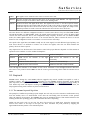
5.3 Target Memory
(C) 2013, SatService GmbH
www.satnms.com
ACU-RMU-UM-1301 Page 34/79
SatService
Gesellschaft für Kommunikationssysteme mbH
The page 'Targets' gives access to the ACU's target memory. The ACU is capable to remember the pointing
(and tracking parameters, if the ACU has the tracking module installed) of up to 99 satellites. Managing
these memories is done with the 'Targets' page.
The page displays a table with all pointings actually stored. By clicking the icons in the table, settings may be
stored, recalled or deleted:
Go
If a memory location has stored a pointing, the table shows a blue arrow in the 'Go' column of
the table. Clicking to this arrow recalls the settings stored for that target and moves the antenna
to the stored pointing. The ACU displays a confirmation dialog before it actually recalls the
target memory. Only if you click to 'Submit' in this dialog, the antenna moves to the stored
location.
Save
For each memory location the table shows a floppy disk icon in the 'Save' column. Clicking to
this icon saves the actual pointing (and tracking parameters if applicable) to the selected
memory location. Again, there is a confirmation dialog page before the data actually is saved.
Delete
Analogous to the 'Save' icon, the table shows an eraser icon in the 'Delete' column. The icons
only are shown for the memory locations which are in use. Clicking to the eraser icon clears
the selected memory location after a confirmation inquiry.
Numeric The table contains an additional row at the bottom labeled 'Numeric orbit position'. Clicking to
orbit
the blue arrow icon in this row opens a dialog where you are requested to enter the orbit
position position of a satellite you want the antenna to point to. After you pressed 'Submit' in this
dialog, the ACU computes the antenna pointing for the orbit position you entered and
immediately moves the antenna to the calculated position. To make this function work
satisfactory, it is necessary to have the geodetic location of the antenna entered at the Setup
page with a sufficient accuracy.
The first target location, labeled 'adaptive tracking memory', is reserved for special purposes: If you store to
this target location, this saves the tracking parameters and the tracking memory as well. When this memory
location is recalled later on, the parameters and the memory contents are restored. This may be useful to
track another satellite for a couple of hours and then to return to the first satellite. If the tracking memory
has been saved before the antenna has been moved to the second satellite, it may be restored after the
antenna returned to the old position.
You should not use the first target location for general purposes in order to keep it available for the short
time storage described above.
Targets Page Example:
5.4 Tracking Parameters
sat-nms ACUs with the tracking function installed give access to the tracking mode and the fine tune
parameter which lets you adapt the tracking to the individual requirements of the antenna and the satellite
(C) 2013, SatService GmbH
www.satnms.com
ACU-RMU-UM-1301 Page 35/79
SatService
Gesellschaft für Kommunikationssysteme mbH
you are tracking to. ACUs without tracking function show an empty page at this place.
Tracking mode
The tracking mode parameter selects the tracking method, the ACU actually
uses. Possible selection are:
OFF
No tracking is performed.
STEP
Step track mode. In regular intervals, the antenna performs
small search steps to optimize the pointing. Chapter '8.3.0
Step Track' gives more information about this mode.
ADAPTIVE The adaptive tracking mode works the same way as step
track, but it additionally is capable to predict the satellite's
position when the beacon reception fails. It computes
mathematical models of the satellites motion from the step
track results recorded over a certain time. Details about this
tracking mode are given in chapter '8.4.0 Adaptive
Tracking'.
PROGRAM The program tracking mode is different from the modes
above. The ACU moves the antenna along a path which is
described in a data file. No beacon reception is required for
this. You have to create such a data file and copy it with
FTP to the ACU before you can use this mode. SatService
GmbH provides a PC software which lets you easily create
data files for program track from commonly used ephemeris
data sets for geostationary satellites. Chapter '8.5.0 Program
Tracking' describes this tracking mode more detailed.
CLEAR MEMORY
Clicking to this mark clear the tracking memory. You should do this when
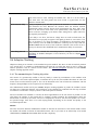
you start to track a new satellite. Clearing the tracking memory about half
an hour after tracking started significantly improves the quality of the first
adaptive tracking model which will be evaluated after 6 hours of tracking.
This is because the model does not get disturbed by the first search steps the
antenna does until the optimal pointing to the satellite is found.
Tracking step size
The tracking step size is a very important parameter for the performance of
the tracking. It defines the size of every depointing step, the ACU makes in
order to find out where the optimal antenna pointing is. Setting too high
values will cause significant signal degradations during the step track cycle
because the antenna moves a too large amount away from the satellite.
Setting the value too small will let the beacon level jitter mask the level
differences caused by the test steps, the antenna will not track the satellite
properly.
The step size is specified as a percentage of the antenna's half 3dB
beamwidth. The ACU calculates the beamwidth from the antenna diameter
and the beacon frequency. Expressing the step size in this relative way
keeps the value in the same range, regardless of the type of antenna. The
recommended value for this parameter is 15-20%. You may want to start
with 20% and try to reduce down to 15% if the signal degradation during
tracking becomes too high.
The tracking step size is a common parameter for both axes. If both axes
behave differently, you can tweak the antenna diameter settings in the
setup. Specifying a larger diameter makes the ACU using a smaller step size
for this axis.
(C) 2013, SatService GmbH
www.satnms.com
ACU-RMU-UM-1301 Page 36/79
SatService
Gesellschaft für Kommunikationssysteme mbH
If the tracking step seems to be completely out of range, you should check
if the beacon frequency is set properly. The frequency must be the true
receive frequency at the antenna, entered in MHz, not an L-band frequency
or other IF.
Tracking cycle time
The cycle time specifies how often the ACU shall perform a step track
cycle. The value is to be entered in seconds. In fact, the parameter does not
specify a cycle time but the sleep time between two tracking cycles. This
means, the true cycle time is the time the ACU needs to perform one step
track cycle plus the time entered here. 300 seconds (5 minutes) is a good
starting value for this parameter. Inclined orbit satellites probably will require
a shorter cycle time, very stable satellites can be perfectly tracked with one
step track cycle every 15 minutes (900 seconds). The maximum cycle time
accepted by the ACU is 1638 seconds.
Measurement delay
During a steptrack cycle, the ACU positions the antenna to a certain offset
and then measures the level. Between the moment when the antenna
reached commanded position and the beacon level measurement the ACU
waits some time to let the beacon level settle. The optimal delay value
depends on the beacon receiver's averaging / post detector filter setting and
is a quite critical for the steptrack performance.
If the delay is too short, the beacon voltage does not reach its final value,
the steptrack does not properly recognize if the signal goes better or worse
after a test step. If the delay is too long, the impact of fluctuation to the
measures level grows and may cover the small level difference caused by
the test step. With the sat-nms LBRX beacon receiver, best results are
achieved if the receiver is set to 0.5 Hz post detector filter bandwidth and a
measurement delay of 1500 msec.
Recovery delay
After the ACU has done the tracking steps for the elevation axis, it waits
some time before it starts tracking the azimuth axis. This is to let the beacon
level settle after the final position has been found. A typical value for this
parameter is 4000 msec.
Level averaging
When measuring the beacon level, the ACU takes a number of samples and
averages them. The standard value of 5 samples normally should not be
changed. Larger values will slow down the ACU execution cycle.
Level threshold
If the beacon level falls below this threshold value, the ACU does not
perform a step track cycle. If the level falls below the threshold during the
steptrack cycle, the cycle gets aborted.
If the ADAPTIVE tracking is enabled and there is enough data in the
tracking memory, the ACU computes a mathematical model from the stored
data and predicts the antenna pointing position from the extrapolation of the
model. If the tracking mode is set to 'STEP', the ACU leaves the antenna
where it is if the beacon level drops below the limit.
Adjusting the threshold level that adaptive tracking is switched as expected
must be done carefully and may require some iterations, specially if the
beacon is received with a low C/N. A good starting value for the threshold
is 10 dB below the nominal receive level or 2 dB above the noise floor the
beacon receiver sees with a depointed antenna, whatever value is higher.
(C) 2013, SatService GmbH
www.satnms.com
ACU-RMU-UM-1301 Page 37/79
SatService
Gesellschaft für Kommunikationssysteme mbH
To turn off the monitoring of the beacon level (this in fact inhibits the
adaptive tracking), simply set the threshold the a very low value (e.g. -99
dBm)
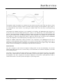
Smoothing interval
This parameter controls the smoothing function. Setting it to zero disables
smoothing. Smoothing lets the ACU point the antenna to positions evaluated
from a simple model calculated from the step track peaks of the recent few
hours. A detailed description of this function you find at chapter '8.3.3
Smoothing'
Peak jitter threshold
If the jitter value of at least one axis exceeds this threshold, the ACU raises
an 'model fault'. If this happens three consecutive times, the ACU resets the
models of both axes. Adaptive tracking will be possible not until 6 hours
after this happens.
During adaptive tracking, the ACU evaluates for each axis a figure called
jitter. The jitter value describes standard deviation of the measured peak
positions with respect to the positions calculated from the (currently
selected) model. The figure is also expressed as a percentage of the
antenna's beamwidth, low values indicate, that the model ideally describes
the antenna's path. High values indicate that's something wrong. The step
track results may be to noisy at low amplitudes or the model does not fit at
all. This may be the case if a satellite gets repositioned in the orbit.
A typical threshold value is 20%, this will detect very early that a model
does not fit to describe the satellite's motion. If this value causes false alarms
too often, you may want to raise the threshold to 50%. Setting it to 0
switches the threshold monitoring completely off.
AZ Maximum model type These settings let you limit the adaptive model to a simpler one, the ACU
EL Maximum model type would choose by itself. The maximum model type can be set individually
for each axis. Normally you will set both axes to 'LARGE', which leaves the
model selection fully to the ACU's internal selection algorithms.
In cases where the ACU seems to be too 'optimistic' about the quality of the
step track results, the maximum model on one or both axes may be limited
to a more simple and more noise-resistant model. Specially inclined orbit
satellites which are located close to the longitude of the antenna's geodetic
location may require this limitation for the azimuth axis. With such a
satellite, the elevation may move several degrees while the azimuth shows
almost no motion.
Please refer to chapter 8.3 Steptrack, 8.4 Adaptive Tracking and 8.5 Program Tracking for more detailed
informations about the tracking algorithms.
Tracking Parameters Page Example:
(C) 2013, SatService GmbH
www.satnms.com
ACU-RMU-UM-1301 Page 38/79
SatService
Gesellschaft für Kommunikationssysteme mbH
5.5 Test Page
The page 'Test' displays the electrical / logical level of all inputs and outputs of the ACU. This helps you to
install the ACU or to identify a malfunction of peripheral components. Below some information how to
interpret the values in this page are given.
Electrical I/O Levels
The electrical state of an input or output is indicated by the HI / LO label displayed with the signal. HI
means that current is flowing through the optocoupler for this input or output. LO means that no current
flows. As some signals are defined to be 'true' when a switch is opened, the electrical level of the signal not
necessarily describes the logical level of this signal, too.
Logical I/O Levels
The logical level of an input or output is described by it's color: Green means this signal is inactive, OK or
'false'. Read means the signal is active or 'true'.
Toggling output levels manually
The 'Test' page also lets you toggle the actual state of each output signal simply by clicking to the underlined
HI/LO mark of the signal. If you do this, you should consider the following:
The ACU sets the motor driver outputs eight times a second for each axis having the motor driver type
set to 'DIR-START' or 'DUAL-START'. This immediately will overwrite any change you make. If you
want to test if the motor driver outputs command the motor driver as expected, switch the motor driver
type for this axis to 'NONE' at the Setup page before you set the outputs manually.
The 'Test' page is re-read by the Web-browser about once a second. Some browsers seem to ignore
mouse clicks occasionally due to the screen refresh.
Hardware Test Page Example:
(C) 2013, SatService GmbH
www.satnms.com
ACU-RMU-UM-1301 Page 39/79
SatService
Gesellschaft für Kommunikationssysteme mbH
5.6 Setup
The page 'Setup' contains the ACU's installation parameters. The page displays a table with the parameters
actually set. Each parameter value is a hyper-link to a separate page which lets you change this parameter.
This parameter change page shows the actual parameter setting either in an entry field or in a drop down
box. You may change the parameter to the desired value and then click to the 'Submit' button to pass the
changed value to the ACU ODM. The ACU automatically returns to the setup page when the parameter has
been changed. To cancel a parameter modification you already started, either use the 'Back' button of you
w e b browser or click to the 'Setup' button on navigation bar. Both returns to the setup page without
changing the parameter you edited.
The table below lists the settings provided by this page.
General
This section of the setup page contains some general setup parameters.
Parameter Description
Name
Axes
control
mode
Date
The ACU knows two axes control modes. The PARALLEL mode treats the
azimuth/elevation axes independently. If a new pointing is commanded, both motors are
activated in parallel, the antenna moves to the new location in the shortest possible time. In
SEQUENTIAL mode, the ACU does not move the elevation axis while the azimuth motor is
running. The antenna movement is done sequentially: First azimuth, then elevation. You
should prefer the PARALLEL mode unless special conditions require a sequential antenna
movement. The performance of the ACU in terms of pointing speed and wind load
compensation will be much better in PARALLEL mode.
/ By changing this value you can set the internal clock of the ACU. The clock is set as soon
(C) 2013, SatService GmbH
www.satnms.com
ACU-RMU-UM-1301 Page 40/79
SatService
Gesellschaft für Kommunikationssysteme mbH
time
you click to the 'Submit' button in the data entry dialog. The most precise method to set the
time is to enter a time one or two minutes ahead and click to 'Submit' when this time is
reached.
RS485
address
With this parameter you select the device address used control the ACU through a
interface. See chapter 7.3 The RS232 remote control interface for more information
this. At ACU-RMU and ACU19 this parameter has to be set to 'NONE'. If you use
nms Handheld this parameter has to be set to 'TERM'. The Handheld function
implemented in ACU-RMU and ACU19 Version.
serial
about
a satis not
Watchdog The AUX 8 output may be configured to act as a heartbeat output. If enabled, the output
pulse on switches every 1000 ms between on/off. If using this signal for an external watchdog circuit,
AUX8
be aware that in adaptive tracking mode delays of some seconds are possible while the acu
calculates the orbital model.
Display
refresh
With this parameter you select the refresh-rate of the ACU's main window. This parameter is
available from software version 2.1.007 or higher.
Note
The ACU's pointing page by default shows the title 'Antenna pointing'. By entering a
different text here, you can make the ACU show a customized title.
Azimuth / Elevation / Polarization
The Azimuth / Elevation / Polarization sections contains the parameters which are specific to the individual
axis. They are the same for each axis.
Parameter
Name
Description
Antenna
diameter
Set this parameter to the dish diameter. Units with the tracking function installed use this
value to estimate some tracking parameters. With offset antennas, the diameter settings are
different for the azimuth / elevation axes. This lets the ACU calculate suitable tracking step
sizes individually for each axis.
Step delta
This parameter defines size of a step the antenna moves when you click to the arrow
buttons on the ACU main page. If you are using the arrow buttons to fine-tune the antenna
pointing manually, the best value is the pointing hysteresis described below. This lets you
move the antenna the smallest possible step when you click to an arrow button. For special
applications however it might be helpful to set the step delta to a much greater value. This
parameter is not available with the polarization axis, there the step delta is fixed 1°.
Position
sensor
type
With this parameter you set the type of position sensor the ACU shall read for this axis.
Principally, the ACU is capable to read SSI, RESOLVER and ANALOG type position
sensors. The selected sensor type must match the type of interface board installed in your
ACU. It is not possible to switch from SSI to RESOLVER or vice versa without changing the
interface module.
When selecting a SSI type position encoder, also the number of bits and the encoding
scheme must be selected. For the position sensor type parameter these values are combined
to one name. E.g. 'SSI-13G' means 13 bit, Graycode SSI sensor, 'SSI-24B' means 24 bit
binary encoded SSI sensor.
Beside the SSI-xxX, RESOLVER and ANALOG selections this parameter offers the choice
'NONE' which tells the ACU not to read a position encoder at all. With this selection you can
tell the ACU if the polarization is not to be controlled by the ACU.
If you are using multiturn SSI encoders you will have to scale the reading (See 'Calibration
scale' below).
(C) 2013, SatService GmbH
www.satnms.com
ACU-RMU-UM-1301 Page 41/79
SatService
Gesellschaft für Kommunikationssysteme mbH
Pre scale The pre-scale calibration offset is added to the raw position encoder reading before scaling is
offset
applied. The pre scale offset is defined as an 8-digit hexadecimal value in normalized
position encoder ticks (00000000-FFFFFFFF equivalent to the full range of the encoder (0360° with single turn encoders).
The pre scale offset must be adjusted to avoid any 7FFFFFF to 8000000 overflow within the
used range of the encoder. The value is added to the encoder reading, neglecting an overfly
eventually occurring. Thus, the offset implements a 360° turnaround automatically.
The pre scale offset may be computed and set manually or by assistance of the ACU's
automatic calibration function as described below.
Post scale The post scale calibration offset is added to the position value before the angle value is
offset
displayed, but after the scaling is applied. The post scale offset is defined in degrees of
AZ/EL/POL.
The ACU provides a function to calculate and set both, the pre-scale and the post-scale
offset from a known pointing:
1. Set the calibration scale / gear ratio for the axis (this calibration parameter is described
with the next paragraph).
2. Set the soft limits of the axis to preliminary values. In most cases this needs not to be
very accurate, the ACU needs this information to calculate the pre-scale offset to shift
the encoder overflow outside the used range.
3. Optimize the satellite pointing for the reception from a satellite for which the azimuth
and elevation values are known.
4. Click to the 'calc' label beside the calibration offset.
5. Enter the known pointing angle for the satellite and click to submit.
6. The ACU calculates and sets the calibration offsets to a value so that the actual
pointing is displayed as the angle you entered.
For the azimuth axis there is another offset which also is taken into account, the 'Antenna
course'. This value is provided for mobile applications where a compass reading has to be
included into the azimuth value.
Calibration Normally the ACU assumes that the full range of a position sensor corresponds 360°. If you
scale
are using a multiturn position sensor or if the position sensor is mounted to the shaft of a
gear rather than to the antenna axis directly, the position sensor reading must be scaled. The
displayed angle is computed as follows:
displayed-value = ((raw-reading+pre-scale-offs) * scale) + pos-scale-offs
Mathematically a scale value of 1.0 disables the scaling. Beside this, the ACU also accepts
the special value 0 to disable scaling at all. If you set 1.0, the ACU performs the scaling with
this factor. With the value 0 the scaling is skipped completely, including the conversion of the
reading to floating point. This ensures, that the full accuracy is retained in cases where no
scaling is necessary.
Sense
invert
With this parameter you easily can reverse the sense of a position sensor. The sense should
be as follows:
Azimuth: The antenna looks more to the west for larger values.
Elevation: Larger values mean higher elevation.
Polarization: The feed turns clockwise (when looking through the antenna to the
satellite) for increasing values. When operated on the southern hemisphere, the
(C) 2013, SatService GmbH
www.satnms.com
ACU-RMU-UM-1301 Page 42/79
SatService
Gesellschaft für Kommunikationssysteme mbH
polarization sense must be set the other way round.
Motor
The ACU knows two different configuration modes to control a motor driver. They are
driver type called DIR-START and DUAL-START. In DIR-START mode, the FWD signal switches the
motor on/off, the REV signal controls the motor direction. This is the configuration many
frequency inverters use. In DUAL-START mode, the FWD signal switches the motor on in
forward direction, REV activates the motor in reverse direction. This configuration mode is
convenient to control a motor with relays. Beside the modes DIR-START and DUALSTART you may set the motor driver type to NONE which prevents the ACU from
controlling the motor at all.
Low
speed
threshold
The ACU controls a motor at two speeds. If the actual position is far away from the target
value, the ACU commands the motor to use the fast speed. Once the antenna comes close to
the target value, the ACU slows down the motor. The low speed threshold sets the angle
deviation which lets the ACU use the fast motor speed.
Pointing
hysteresis
The ACU performs the motor control as a closed loop: if the angle reading and the target
value differ, the motor is switched on to compensate the difference. If the difference is less
than the hysteresis value, the ACU leaves the motor switched off. This prevents the antenna
from oscillating around the target value.
Motor
timeout
The ACU monitors the position readings while the motor is running. If there is no change in
the position readings for some time, the ACU assumes to motor to be blocked and switches it
off. This 'motor timeout' fault must be reset by the operator to release it. A timeout value 0
disables the timeout.
Lower
limit
The minimum target value accepted at the user interface and via remote control. This
software limit prevents the ACU from running the antenna to the limit position under normal
conditions.
Upper
limit
The maximum target value accepted at the user interface and via remote control. This
software limit prevents the ACU from running the antenna to the limit position under normal
conditions.
Beacon Receiver
Parameter Description
Name
Beacon
RX type
Selects the source of the beacon level the ACU shall use. Available options are SATNMS and
VOLTAGE. In SATNMS mode the ACU reads the beacon level from a sat-nms beacon
receiver via UDP, in VOLTAGE mode the A/D converter input of the ACU is read. Please
mention, that in SATNMS mode, the beacon receiver must be set to send UDP datagrams to
the ACU/ODM.
Beacon
The IP address of the beacon receiver. Applicable only in SATNMS mode.
RX
IP
address
Beacon
RX
voltage
scale
The scale factor for the analog beacon level input. The value must match the scaling of the
beacon level signal.
Beacon
The beacon level which is displayed if the ACU recognizes 0V beacon level input.
RX
0V
level
Location
(C) 2013, SatService GmbH
www.satnms.com
ACU-RMU-UM-1301 Page 43/79
SatService
Gesellschaft für Kommunikationssysteme mbH
Parameter Description
Name
GPS
receiver
type
Defines the type of GPS receiver the ACU uses to read its geodetic location.
'NONE' tells the ACU that no GPS receiver is connected. The geodetic position of the
Antenna has to be entered manually. The ACU synchronized its internal clock to the CMOS
clock chip on the board.
'NMEA' tells the ACU to expect messages from a NMEA GPS receiver connected to the
serial interface at CON8, pins 1-3. The ACU automatically sets the antenna's geodetic
location to the values received and synchronizes the clock to the GPS timestamps. If no
NMEA messages are received, the ACU states a fault.
Antenna
course
The Antenna course is an additional offset which is included into the azimuth calibration. It is
used for mobile antennas to set the orientation of the antenna without recalibrating it. For
stationary antennas this value always should be set to 180°.
Antenna
longitude
The geodetic longitude of the antenna. For a precise orbit to pointing calculation this value
should be entered with 0.001° accuracy.
Antenna
latitude
The geodetic latitude of the antenna. For a precise orbit to pointing calculation this value
should be entered with 0.001° accuracy.
Antenna
abs.
altitude
The absolute altitude over sea of the antenna location.
Orientation
Parameter Name Description
Compass type
Applicable only for car-mobile variants of the ACU
Inclinometer type Applicable only for car-mobile variants of the ACU
Nick offset
Applicable only for car-mobile variants of the ACU
Roll offset
Applicable only for car-mobile variants of the ACU
SNMP Control
From Software version 2.1.007 or higher, the sat-nms ACU contains an SNMP agent listening at UDP port
161. The SNMP agent provides a common subset of the MIB-II system / interface parameters and gives
full access to the remote control capabilities of the sat-nms ACU with a number of MIB objects placed in
the private.enterprises tree.
The actual MIB file defining the ACU's private MIB may be downloaded from the ACU itself by FTP (user
'service', password 'service'). The file 'ACUODM.MIB' contains all necessary information.
Parameter
Name
Description
SNMP
read
community
Sets the SNMP community string expected for read access. The default is 'public'.
SNMP
write
Sets the SNMP community string expected for write access. The default is 'public'.
(C) 2013, SatService GmbH
www.satnms.com
ACU-RMU-UM-1301 Page 44/79
SatService
Gesellschaft für Kommunikationssysteme mbH
community
SNMP trap Sets the SNMP community string sent with traps. The default is 'public'.
community
SNMP
traps
This parameter decides if the SNMP traps are enabled or disabled.
SNMP
system
name
The ACU replies to MIB-II sysName requests with the text entered at this place.
SNMP
system
location
The ACU replies to MIB-II sysLocation requests with the text entered at this place
SNMP
system
contact
The ACU replies to MIB-II sysContact requests with the text entered at this place.
MIB File
click here to download the MIB file
SNMP trap Enter up to 4 trap destination IP addresses (dotted quad notation) to make the ACU sending
IP 1-4
traps by UDP to these hosts. Setting the parameter to 0.0.0.0 disables the trap generation.
Access Control
User
Here you can define the password for the 'user' login. Default password is 'user'. When you
password are logged in as 'user' you can command the antenna pointing, set the tracking parameters (if
applicable) and store / recall targets. You can't modify the setup parameters or issue low level
commands on the test page while logged in as 'user'.
Admin
Here you can define the password for the 'admin' login. Default password is 'admin'. When
password you are logged in as "admin" you have full access to all parameters of the ACU, including the
setup and the tweaks on the test page.
(C) 2013, SatService GmbH
www.satnms.com
ACU-RMU-UM-1301 Page 45/79
SatService
Gesellschaft für Kommunikationssysteme mbH
Setup Page Example
5.7 Handheld Terminal
The antenna may be moved by means of the optional handheld controller. The Handheld function is not yet
available at ACU-RMU and ACU19 Version.
Startup
Set parameter 'RS485 address' on the ACUs Setup-page to 'TERM'. This enables communication between
the ACU and the sat-nms handheld.
Connect the Handheld with the provided cable (Handheld: 9pol DSUB + Power supply, ACU-Cabinet: 15pol
DSUB). After connecting the Handheld, push the Redraw button once. The start-up screen, that shows the
(C) 2013, SatService GmbH
www.satnms.com
ACU-RMU-UM-1301 Page 46/79
SatService
Gesellschaft für Kommunikationssysteme mbH
DSUB). After connecting the Handheld, push the Redraw button once. The start-up screen, that shows the
installed software version is displayed for a few seconds. After that the menu for controlling the antenna is
displayed automatically.
Operation
Emergency STOP, stops all Motors immediately, it has to be released by pushing the -button
Releases the motor-lock that was set by pushing the STOP-button.
Back to start screen
Turns the polarisation counterclockwise
Selects the step-size: small steps: x°/keypress (x is the value that was set on the setupscreen), large steps: 10*x°/keypress, continuous mode: the antenna moves as long until the button is pushed or a limit switch or limit value is reached.
Turns the polarisation clockwise
Moves the antenna up (EL)
Moves the antenna to the left (AZ)
Stops the antenna movement (only in continuous mode)
Moves the antenna to the right (AZ)
Moves the antenna down (EL)
(C) 2013, SatService GmbH
www.satnms.com
ACU-RMU-UM-1301 Page 47/79
SatService
Gesellschaft für Kommunikationssysteme mbH
6 Frontpanel operation
The rack mountable version of the sat-nms ACU provides a LCD and a small keyboard at the front panel
for operating the device locally as an option. The capabilities of the front panel operation are designed to
operate the ACU locally. It is possible to select a new target, move the antenna incremental, set new pointing
angles or select another step track mode. Advanced configuration parameters are available over the web
interface. Please start reading at chapter 5.1 for more information.
Display
The 2-line display normally shows the actual target name, the angle of the three axes, the step track mode
and the beacon level. During menu operation it is used to view and edit some parameter of the ACU.
LEDs
Three LEDs at the front panel signal the summary state of the ACU.
The 'Move' LED is on while a motor is on.
The 'Limit' LED is on while an end switch of the antenna is activated. If so, the 'Alarm' LED is also
on.
The 'Alarm' LED is on while the ACU19 is in alarm state.
Keys
The front panel keyboard provides beside the numeric keys four arrow keys and two keys named ENTER
and CLEAR. Some keys have a second meaning. The first meaning of the keys remains constant through
most levels of the menu:
The ENTER key descends in the menu tree, accepts and stores changed values
The CLEAR key leaves to higher menu levels, abandons changes when editing parameters. It
also resets the alarm buzzer when in display mode.
The arrow keys navigate in the menu.
0..9
The number keys are to enter numeric parameters.
If STEP MOVE is selected in the menu the following numeric keys have a new function.
7 Move the polarization counterclockwise
9 Move the polarization clockwise
8 Move the elevation down
(C) 2013, SatService GmbH
www.satnms.com
ACU-RMU-UM-1301 Page 48/79
SatService
Gesellschaft für Kommunikationssysteme mbH
2 Move the elevation up
4 Move the azimuth east
6 Move the azimuth east
For all directions: view from behind antenna.
If one or all motors are moving, they can stop with the following key:
0 Stop every motor
6.1 Display mode
The display mode shows the actual reading and some additional information in the display. This is the
default mode, the ACU enters it automatically after power on. Depending on the selected tracking mode, the
default display looks like this:
The upper display line shows the actual target name and the three axes angles. The lower line shows the
selected tracking mode depending on tracking mode, the size of the tracking memory and the model data or
nothing, and the beacon level.
While the ACU is not in a regular state, the display shows a message. The ordinary contents of the display
and the message are shown alternately, the message blinks on the display. The following messages may be
displayed at the corresponding position in the display.
At the corresponding angle position:
FAULT
General ACU Fault
TIMEOUT Motor moves, but the position encoder does not react
HI-LIMIT
High limit switch is activated
LOWLIMIT
Low limit switch is activated
STOPPED
Motor stopped, over Web interface or with the STOP-Button on front panel
BEAC FLT If the ACU reads the beacon level via TCP/IP from sat-nms LBRX and the beacon
receiver does not respond
LOW
BEAC
Low beacon signal
If more than one of the above conditions occurs, only that one with the highest precedence is shown. This
means for example that the HI-LIMIT state precedes over the LO-LIMIT state.
6.2 The main menu
The menu mode lets you view and change some ACU settings. From the display mode, you enter the menu
by pressing the key
. To leave the menu, repeatedly press the key
until the display screen appears
(C) 2013, SatService GmbH
www.satnms.com
ACU-RMU-UM-1301 Page 49/79
SatService
Gesellschaft für Kommunikationssysteme mbH
again. If there are no keystrokes for 1 minute, the ACU automatically leaves the menu and returns to display
mode. The menu structure is shown below:
MENU
SELECT TARGET
STEP MOVE
SET AZIMUTH
SET ELEVATION
SET POLARIZATION
SET TRACKING MODE
To navigate in the menu, use
. To select a menu press
menu level, pressing it twice returns to display mode.
. Pressing
once returns to the main
6.3 Select targets
In the SELECT TARGET menu, it is possible to select a saved target. To navigate between the targets use
. Press
to recall a selected target.
After a target recall, the display returns to the main menu. Press
about a 1 minute for automatically return.
to return to the default display or wait
6.4 Step move
The antenna can be moved over the front panel with the STEP MOVE menu. The corresponding keys are
listed below:
7 Move the polarization counterclockwise
9 Move the polarization clockwise
8 Move the elevation down
2 Move the elevation up
4 Move the azimuth east
6 Move the azimuth east
Press a key one time, moves the antenna one step in the corresponding direction. The step size is defined at
the Web interface.
6.5 Editing Numeric Parameters
(C) 2013, SatService GmbH
www.satnms.com
ACU-RMU-UM-1301 Page 50/79
SatService
Gesellschaft für Kommunikationssysteme mbH
To change a numeric parameter like Azimuth, Elevation or Polarization. Here an example for the azimuth
axis: select SET AZIMUTH from the main menu.
The lower display line shows the actual value. You enter the new value, using the number keys. The digits
fill the entry field from right to left, like with a pocket calculator. The key
may be used to delete the last
digit.
To accept the edited value, press
. This checks the entered value against its limits and executes the
parameter change. Pressing
twice (the first key press clears the display) leaves the editing mode without
changing anything.
6.6 Set tracking mode
In the SELECT TRACKING MODE menu, you can change the tracking mode as shown below:
OFF
STEP
ADAPTIVE
PROGRAM
For detailed information about tracking please refer to chapter 8.3 Step Tracking, chapter 8.4 Adaptive
Tracking and chapter 8.5 Program Tracking.
(C) 2013, SatService GmbH
www.satnms.com
ACU-RMU-UM-1301 Page 51/79
SatService
Gesellschaft für Kommunikationssysteme mbH
7 Remote Control
T he sat-nms ACU may be controlled remotely by a monitoring and control application either through the
TCP/IP interface or through a serial RS232 interface (RS232 not yet implemented in ACU19 and ACURMU). Both communication methods use the same commands and parameters. However, there are different
frames around each message depending communication method used.
Controlling the device from the web interface, the TCP/IP remote control interface or via the serial interface
is completely equal, commands may sent to any interface at any time, the ACU will use the parameter it
receives last.
7.1 General command syntax
The ACU knows a number of parameters, each identified by a parameter name. To set a certain parameter
to a new value, a message:
name=value
has to be sent to the ACU. The ACU interprets this command, checks the range of value, sets the internal
parameter and then answers:
name=value
The value in the reply is the value actually recognized by the ACU. For instance, if the requested value was
out of range, the replied (and internally used) value is limited to the applicable minimum or maximum.
To read a parameter from the ACU, instead of a new parameter value a question mark is sent:
name=?
The ACU replies the actual value in a complete message:
name=value
A complete list of the parameter the ACU knows is shown later in this document in chapter Parameter list.
Below, some common rules applying to the remote control message syntax are summarized.
Parameter names always are of lower case letters, most of them are four characters long.
Non-numeric parameter values always are written in upper case.
Numeric (floating point) values may be specified with an arbitrary precision, however the device will
reply only a fixed number of places. The ACU recognizes a decimal point ('.'), numbers must not
contain any commas.
There must not be any whitespace in front or after the '=' in a message.
If the command/query is not of the form name=value or name=?, the ACU replies the message ?
SYNTAX.
If the message syntax is OK, but contains an unknown parameter name is used, the reply is ?
UNKNOWN
Numeric parameters are cut to the limits defined for this particular parameter.
Misspelled choice values cause the ACU to set the first value of the choice list.
Assigning a value to a read-only parameter will cause no fault, however the ACU will overwrite this
parameter immediately or some seconds later with the actual value.
7.2 The TCP/IP remote control interface
(C) 2013, SatService GmbH
www.satnms.com
ACU-RMU-UM-1301 Page 52/79
SatService
Gesellschaft für Kommunikationssysteme mbH
Controlling the ACU through the network is done by means of HTTP GET requests. Setting parameter
values or querying readings or settings, all is done by requesting HTTP documents from the ACU. The
message to the ACU thereby is coded into the URL as a CGI form parameter. The ACU replies a one line
document of the MIME type 'text/plain'.
The document name for remote control is /rmt, hence (assuming the ACU is listening to the IP address
10.0.0.1), requesting a document with the URL
http://10.0.0.1/rmt?levl=?
Will let the ACU reply the actual beacon level in a one line text document:
levl=-52.31
This way all parameters may be queried or set, you may use your favorite web browser to try out the
remote control of the ACU manually.
7.3 The RS232 remote control interface
Beside the network interface, the ACU also provides an RS232 serial port which can be used to control the
device remotely. Depending on the device address set, the ACU either runs framed protocol with start/stop
characters and checksum or it provides a dumb terminal interface. The RS232 interface always operates at
9600 baud, no parity, 8 data bits, one stop bit.
This interface is not yet implemented in the ACU19 and ACU-RMU! At these versions, you have to select
'NONE' to enable the function of optional frontpanel display and keyboard. If another setting is selected, an
optional frontpanel and keyboard has no function.
If an address 'A' .. 'G' is selected, the ACU expects each message it receives to be packed into a frame as
described below.
char # example description
1
{
start character, always '{'
2
A
device address (A..G)
3
l
first character of the message body
.
e
message body ...
.
v
..
.
l
..
.
=
..
n-1
?
last character of the message body
n
}
end character, always '}'
n+1
.
checksum
The checksum byte is calculated using an algorithm as implemented by the following formula:
This protocol type is known as MOD95- or Miteq protocol . The ACU also packs its reply in a protocol
(C) 2013, SatService GmbH
www.satnms.com
ACU-RMU-UM-1301 Page 53/79
SatService
Gesellschaft für Kommunikationssysteme mbH
frame as described above. Incomplete frames, checksum errors or address mismatches let the ACU ignore
the message. The time between the characters of a message must be less than 5 seconds or the ACU will
treat the message as incomplete.
If the ACU is set to the device address 'NONE', it uses a simple line protocol instead of the framed protocol
described above. Messages sent to the ACU have to be terminated with a carriage return character (ASCII
13), the ACU terminates replies with a CR/LF pair (ASCII 13/10). There is no echo for characters entered,
hence this protocol easily may be used for computer based remote control.
This setting is also used for allowing communication to an optional frontpanel display and keyboard if
implemented.
If 'TERM' is selected the serial interface is used to allow communication between the ACU and a sat-nms
Handheld. This function is not available at ACU-RMU and ACU19 Version.
7.4 Parameter list
The table below shows the complete list of M&C parameters the ACU knows in alphabetical order. For each
parameter the valid range and a short description is given.
name
range
unit
description
aalt
0 .. 8000
m
Antenna abs.
altitude
%
AZ
Amplitude
°
AZ
Calibration
offset
°
Calculate
offset from
Az. value
aamp
r/o
acal
-360.000 .. 360.000
aclc
acou
-180.000 .. 180.000
°
Antenna
course
addr
A B C D E F G NONE
-
RS485
address
ahys
0.000 .. 2.000
°
AZ Pointing
hysteresis
ainv
NORMAL INVERTED
-
AZ
Sense
invert
%
AZ Peaking
jitter
ajtr
r/o
alat
0.000 .. 90.000
°N
Antenna
latitude
alon
-180.000 .. 180.000
°E
Antenna
longitude
amax
180.000 .. 360.000
°
AZ
limit
Upper
AZ
type
Model
amdt
r/o character string
(C) 2013, SatService GmbH
www.satnms.com
ACU-RMU-UM-1301 Page 54/79
SatService
Gesellschaft für Kommunikationssysteme mbH
amin
0.000 .. 180.000
°
AZ
limit
ammx
SMALL MEDIUM LARGE
-
AZ
Maximum
model type
amnt
AZ-OVER-EL POLAR
-
Antenna
mount type
amot
DUAL-START DIR-START NONE
-
AZ
Motor
driver type
°
AZ Pointing
apos
r/o -180.000 .. 180.000
araw
r/o 00000000 .. FFFFFFFF
Lower
AZ
raw
pointing
asca
0.000000 .. 100000.000000
AZ
Calibration
scale
asen
SSI-13B SSI-13G SSI-17B SSI-17G SSI-18B SSI-18G SSI-19B SSI-19G SSI-20B SSI-20G SSI-24B SSI-24G RESOLVER
VOLTAGE NONE
AZ Position
sensor type
asth
0.0 .. 10.0
°
AZ
Low
speed
threshold
astp
0.000 .. 90.000
°
AZ Step delta
atar
-180.000 .. 180.000
°
Az.
value
atot
0 .. 32000
msec
AZ
Motor
timeout
axmd
PARALLEL SEQUENTIAL
-
Axes control
mode
bavg
1 .. 25
samples Level
averaging
bcfr
1000.000 .. 40000.000
MHz
bcip
aaa.bbb.ccc.ddd
bcof
-200.00 .. 0.00
dBm
Beacon RX
0V level
bcsc
-5.0000 .. 5.0000
V/dB
Beacon RX
voltage scale
bcty
SATNMS VOLTAGE
-
Beacon
type
target
Beacon RX
frequency
Beacon RX
IP address
RX
blev
r/o #.##
dBm
Beacon level
brip
r/o #.##
dB
Beacon level
ripple
dBm
Level
threshold
btrh
-999.00 .. 100.00
(C) 2013, SatService GmbH
www.satnms.com
ACU-RMU-UM-1301 Page 55/79
SatService
Gesellschaft für Kommunikationssysteme mbH
caps
r/o 00 .. FF
Software
capabilities 1)
coty
NONE
-
Compass
type 2)
decl
-90.000 .. 90.000
°
Antenna
declination
dele
0 .. 99
diaa
0.0 .. 100.0
m
AZ Antenna
diameter
diae
0.0 .. 100.0
m
EL Antenna
diameter
%
EL Amplitude
°
EL
Calibration
offset
°
Calculate
offset from
El. value
eamp
ecal
Delete target
r/o
-360.000 .. 360.000
eclc
ehys
0.000 .. 2.000
°
EL Pointing
hysteresis
einv
NORMAL INVERTED
-
EL
Sense
invert
%
EL Peaking
jitter
°
EL
limit
Upper
EL
type
Model
Lower
ejtr
r/o 0 ..
emax
0.000 .. 90.000
emdt
r/o character string
emin
0.000 .. 90.000
°
EL
limit
emmx
SMALL MEDIUM LARGE
-
EL
Maximum
model type
emot
DUAL-START DIR-START NONE
-
EL
Motor
driver type
°
EL Pointing
epos
r/o 0.000 .. 90.000
eraw
r/o 00000000 .. FFFFFFFF
EL
raw
pointing
esca
0.000000 .. 100000.000000
EL
Calibration
scale
esen
SSI-13B SSI-13G SSI-17B SSI-17G SSI-18B SSI-18G SSI-19B SSI-19G SSI-20B SSI-20G SSI-24B SSI-24G RESOLVER
VOLTAGE NONE
EL Position
sensor type
esth
0.0 .. 10.0
EL
(C) 2013, SatService GmbH
°
www.satnms.com
Low
ACU-RMU-UM-1301 Page 56/79
SatService
Gesellschaft für Kommunikationssysteme mbH
speed
threshold
estp
0.000 .. 90.000
°
EL Step delta
etar
0.000 .. 90.000
°
El.
value
etot
0 .. 32000
msec
EL
Motor
timeout
goto
0 .. 99
gpty
NONE
ibit
00000000 .. FFFFFFFF
icty
NONE
-
Inclinometer
type 4)
jtrh
0 .. 100
%
Peak
jitter
threshold
mdly
0 .. 9999
msec
Measurement
delay
mstp
0 .. 1
target
Goto target
-
GPS receiver
type 3)
Input
bits
(described
below)
1 stops all
motors
(STOP at the
Web UI)
0 releases the
stop (RESET
at the Web
UI)
nick
r/o -90.0 .. 90.0
°
Nick angle
niko
-90.0 .. 90.0
°
Nick offset
note
character string
Note
obit
00000000 .. FFFFFFFF
Output bits
(described
below)
orbt
-180.000 .. 180.000
°E
Orbit position
pcal
-360.000 .. 360.000
°
PO
Calibration
offset
°
Calculate
offset from
Pol. value
pclc
pcnt
0 .. 65535
phys
0.000 .. 10.000
°
PO Pointing
hysteresis
pinv
NORMAL INVERTED
-
PO
Sense
invert
(C) 2013, SatService GmbH
Peak count
www.satnms.com
ACU-RMU-UM-1301 Page 57/79
SatService
Gesellschaft für Kommunikationssysteme mbH
pmax
0.000 .. 180.000
°
PO
limit
Upper
pmin
-180.000 .. 0.000
°
PO
limit
Lower
pmot
DUAL-START DIR-START NONE
-
PO
Motor
driver type
°
PO Pointing
ppos
r/o -90.000 .. 90.000
praw
r/o 00000000 .. FFFFFFFF
PO
raw
pointing
psca
0.000000 .. 100000.000000
PO
Calibration
scale
psen
SSI-13B SSI-13G SSI-17B SSI-17G SSI-18B SSI-18G SSI-19B SSI-19G SSI-20B SSI-20G SSI-24B SSI-24G RESOLVER
VOLTAGE NONE
PO Position
sensor type
psth
0.0 .. 10.0
°
PO
Low
speed
threshold
ptar
-90.000 .. 90.000
°
Pol.
value
ptot
0 .. 32000
msec
PO
Motor
timeout
pwda
character string
*
Admin
password
pwdu
character string
*
User
password
target
roll
r/o -90.0 .. 90.0
°
Roll angle
rolo
-90.0 .. 90.0
°
Roll offset
save
0 .. 99
Save target
scnt
r/o 0 .. 65535
Save count
slee
r/o 0 .. 65535
smth
0 .. 6
sec
Sleep time up
to the next
tracking
action
h
Smoothing
interval
srno
r/o character string
Device serial
no
step
command
Step move 5)
stim
character string
Date / time 6)
sver
r/o character string
tage
r/o #.#
(C) 2013, SatService GmbH
Software
version
h
www.satnms.com
Tracking
model age
ACU-RMU-UM-1301 Page 58/79
SatService
Gesellschaft für Kommunikationssysteme mbH
tcyc
1 .. 1638
sec
Tracking
cycle time
tdly
100 .. 9999
msec
Recovery
delay
°C
Temperature
°C
Target
description 7)
temp
r/o #.#
tdsc
0..99 / character string
tflt
r/o 00 .. FF
thrs
r/o #.#
time
r/o character string
Tracking
fault
bits
(described
below)
h
Tracking
memory
Date / time 6)
tlog
1 .. 1
tmod
OFF STEP ADAPTIVE MEMORY PROGRAM
trty
NEVER ONCE FOREVER
Tracking
retry on fault
tnam
character string
Target name
trst
1 .. 1
Reset
tracking
memory
trty
NEVER ONCE FOREVER
Tracking
retry on fault
tsta
Log
tracking
memory
-
r/o character string
tstp
1 .. 100
wdog
OFF ON
to
Tracking
mode 8)
Tracking
state
%
Tracking step
size
ON Sends a
heatbeat to
the AUX 8
output
Remarks:
1) Software capabilities are summed from the following values:
1 = step track & adaptive tracking included
2 = polar mount antennas supported
4 = memory tracking ingluded
2) ACU variants with compass support provide other choices beside NONE for this parameter.
3) ACU variants with GPS support provide other choices beside NONE for this parameter.
4) ACU variants with inclinometer support provide other choices beside NONE for this parameter.
5) for single step move, use following commands:
command description
(C) 2013, SatService GmbH
www.satnms.com
ACU-RMU-UM-1301 Page 59/79
SatService
Gesellschaft für Kommunikationssysteme mbH
ll
Azimuth large step left
l
Azimuth small step left
r
Azimuth small step right
rr
Azimuth large step right
dd
Elevation large step down
d
small step down
u
small step up
uu
large step up
c
Polarisation clockwise step
cc
Polarisation counter clockwise step
6) Use the 'time' parameter to read the actual time used by the ACU. Use the 'stim' parameter to set the
time.
7) This parameter reports the description (name and pointing angles) for a given target number. 'tdsc=12'
e.g. is interpreted by the ACU as a request to report the target description for target no. 12. The reply to this
command is something like 'tdsc=ASTRA 19.2 (167.335/43.412/-15.455)'
8) ACU variants without tracking support only accept NONE for this parameter.
Bit definitions in 'ibit' (input bits and flags):
The 'ibit' value is returned as a 32 bit hexadecimal number. The bit number 0 means the least significant bit,
bit number 31 the most significant bit in this number.
no. name
description
0
IN_PLHLM polarization hi limit
1
IN_PLLLM
polarization lo limit
2
IN_PLFLT
polarization motor fault
3
IN_HBFLT
antenna hub fault
4
IN_AUX1
reserved
5
IN_AUX2
reserved
6
IN_AUX3
reserved
7
IN_AUX4
reserved
8
IN_AZHLM azimuth hi limit
9
IN_AZLLM
azimuth lo limit
10
IN_AZFLT
azimuth motor fault
11
IN_EMERG emergency stop
12
IN_ELHLM elevation hi limit
13
IN_ELLLM
elevation lo limit
14
IN_ELFLT
elevation motor fault
15
IN_COPEN
cabinet open
16
AZMOV
azimuth moving
17
ELMOV
elevation moving
(C) 2013, SatService GmbH
www.satnms.com
ACU-RMU-UM-1301 Page 60/79
SatService
Gesellschaft für Kommunikationssysteme mbH
18
PLMOV
polarization moving
19
MOVING
moving summary bit
20
AZTOT
azimuth timeout
21
ELTOT
elevation timeout
22
PLTOT
polarization timeout
23
TIMEOUT
timeout summary bit
24
TRKPEAK
peaking in progress
25
LOWBEAC
low beacon signal
26
BCRXFLT
beacon receiver fault
27
LIMIT
limit switch summary
28
AZSTOP
azimuth stopped
29
ELSTOP
elevation stopped
30
PLSTOP
polarization stopped
31
GPSFLT
GPS receiver fault
Bit definitions in 'obit' (output bits):
The 'obit' value is returned as a 32 bit hexadecimal number. The bit number 0 means the least significant bit,
bit number 31 the most significant bit in this number.
no. name
description
0
OUT_AZ_FWD
azimuth motor forward
1
OUT_AZ_REV
azimuth motor reverse
2
OUT_AZ_SPD1
azimuth motor low speed
3
OUT_AZ_SPD2
azimuth motor hi speed
4
OUT_AZ_RESET
azimuth motor driver reset
5
OUT_AZ_RESERVE
reserved for extended motor control
6
OUT_AUX1
not used
7
OUT_AUX2
not used
8
OUT_EL_FWD
elevation motor forward
9
OUT_EL_REV
elevation motor reverse
10
OUT_EL_SPD1
elevation motor low speed
11
OUT_EL_SPD2
elevation motor hi speed
12
OUT_EL_RESET
elevation motor driver reset
13
OUT_EL_RESERVE
reserved for extended motor control
14
OUT_AUX3
not used
15
OUT_AUX4
not used
16
OUT_POL_FWD
polarization motor forward
17
OUT_POL_REV
polarization motor reverse
18
OUT_POL_SPD1
polarization motor low speed
(C) 2013, SatService GmbH
www.satnms.com
ACU-RMU-UM-1301 Page 61/79
SatService
Gesellschaft für Kommunikationssysteme mbH
19
OUT_POL_SPD2
polarization motor hi speed
20
OUT_POL_RESET
polarization motor driver reset
21
OUT_POL_RESERVE reserved for extended motor control
22
OUT_AUX5
not used
23
OUT_AUX6
not used
24
OUT_SUMMARY
summary fault relay (1 == OK)
25
OUT_TRACKING
tracking fault relay (1 == OK)
26
OUT_BCPR1
reserved for beacon receiver frequency select
27
OUT_BCPR2
reserved for beacon receiver frequency select
28
OUT_BCPR3
reserved for beacon receiver frequency select
29
OUT_BCPR4
reserved for beacon receiver frequency select
30
OUT_AUX7
not used
31
OUT_AUX8
not used
The meaning of the 'FWD' / 'REV' motor control outputs depend on the motor control mode set for this
axis.
Bit definitions in 'tflt' (tracking faults):
The 'tflt' value is returned as a 8 bit hexadecimal number. The bit number 0 means the least significant bit,
bit number 7 the most significant bit in this number.
no. name
description
0
APEAKFLT
azimuth peaking fault
1
EPEAKFLT
elevation peaking fault
2
MODELFLT model match fault
3
JITTRFLT
jitter fault
4
-/-
not used
5
-/-
not used
6
-/-
not used
7
-/-
not used
7.5 One line read via TCP/IP
For compatibility with the sat-nms power sensor, the ACU also may be polled for an automated monitoring
by the requesting the 'position' document with a HTTP GET command. Assuming the ACU listens to the IP
address 10.0.0.1, the complete URL for the request is:
http://10.0.0.1/point?fmt=txt
The 'fmt=txt' parameter forces the power sensor to reply a one line text document rather than the HTML
coded page which is normally displayed by the web browser.
The ACU answers a 'text/plain' type document which consists of one line. As shown in the example below,
the line consists of a set of keyword - value pairs, separated by '&' characters. Within each pair, keyword
(C) 2013, SatService GmbH
www.satnms.com
ACU-RMU-UM-1301 Page 62/79
SatService
Gesellschaft für Kommunikationssysteme mbH
and value are separated by the '=' character.
apos=174.688&epos=31.456&ppos=-34.5&atar=174.700&etar=31.500&ptar=-34.5&blev=64.33&temp=63.5&obit=FFFF0000&ibit=FFFF0000&
The format does not use fixed column widths for the values, however the precision of floating point values
is always as shown in the example. An application which parses this string should not rely on the order of
the values in the line. Future version of the ACU may provide additional values which not necessarily will
appear at the end of the line. A description of the parameters is given in the chapter Parameter list above.
(C) 2013, SatService GmbH
www.satnms.com
ACU-RMU-UM-1301 Page 63/79
SatService
Gesellschaft für Kommunikationssysteme mbH
8 Theory of Operation
This section gives some background information about how the ACU works.
Chapter 8.1 Angle Measurement describes how the ACU measures the antenna pointing and how it
calculates the angles displayed at the user interface.
Chapter 8.2 Pointing / Motor Control describes the way the ACU performs the antenna pointing and how it
controls the motors.
Chapter 8.3 Steptrack describes the step track method used by sat-nms ACUs providing this function.
Chapter 8.4 Adaptive Tracking describes the adaptive (orbit prediction) tracking method used by sat-nms
ACUs providing this function.
Chapter 8.5 Program Tracking describes the program / file tracking capability built into the sat-nms ACU.
8.1 Angle Measurement
T he sat-nms ACU provides exchangeable interfaces for several types of position sensors. Position sensor
interfaces may be selected individually for each axis. This gives a maximum of flexibility for application
where the sat-nms ACU replaces an existing antenna controller.
Position sensor types
Actually there are three types of position sensor interfaces available for the ACU. The interfaces principally
are field-replaceable, however changing interface boards inside the ACU should be done by skilled personnel
only. ESD protection must be followed when handling the ACU boards. The ACU is capable to interface to
the following types of positional sensors:
SSI
SSI type digital position encoders are the first choice for antennas which are setup from
scratch. They are precise, reliable and provide a standardized interface. The ACU supports
types from 13 to 24 bit resolution, both, gray coded and binary variants. The ACU
provides 5V and 24V supply voltages (200mA max) for the encoders, so external power
supplies may be omitted in most cases.
RESOLVER Many existing antennas are equipped with resolvers. The resolver interface module permits
to re-use these ready mounted and cabled sensors when an old antenna controller is to be
replaced by a sat-nms ACU. The resolver interface board is optimized for the use with 2V
type resolvers which are very common. The interface board drives the resolver with 4Veff /
2000Hz and expects 2Veff at the sin/cos inputs. The resolver interface has 16 bit binary
resolution.
ANALOG
For small antennas with reduced accuracy requirements using analog angle to voltage
sensors (in fact precision potentiometers) is an inexpensive alternative. The analog sensor
interface board may be set up for several voltages to connect to the commonly used sensor
types. The analog interface board uses a 16 bit precision ADC with a temperature
compensated voltage reference.
Angle calibration
Analogous to the modular position interface hardware concept, the ACU software uses configurable drivers
to read the different types of position interfaces. From the user's point of view, the ACU accepts and
displays pointing angles as floating point numbers with 0.001° resolution. Internally the software treats angles
(C) 2013, SatService GmbH
www.satnms.com
ACU-RMU-UM-1301 Page 64/79
SatService
Gesellschaft für Kommunikationssysteme mbH
as 32 bit integer numbers where the full 32 bit range corresponds to 360°. This is equivalent to a resolution
of 0.000000084°.
When the software calculates the pointing angles from the sensor readings, it includes some calibration
parameters configurable at the Setup page. The steps of calculating a pointing angle are as follows:
1.
2.
3.
4.
5.
6.
7.
8.
Get the raw value.
Extend (left shift) the value to 32 bits.
Reverse the sign if this option is set in the setup.
Apply (add) the pre-scale offset.
Convert to degrees.
If the calibration scale is nonzero, multiply by the calibration scale.
Add the post scale calibration offset.
For the azimuth axis add the antenna course, too.
The angle calculated this way may exceed a full circle of 360° if the scaling ensures that there is no
overflow of the encoder reading itself. The value displayed as raw reading at the test page, is the result of
step 2.
8.2 Pointing / Motor Control
T he sat-nms ACU performs the pointing / motor control as a closed control loop, independently for each
axis. If the measured position value differs from the target value, the motor is activated to compensate this
difference. It makes no difference if a new target value has been commanded or if the antenna has moved a
little bit due to a squall.
Hysteresis
To avoid that the motor is switched forth and back all the time, the ACU tolerates small differences between
measured and target value within a hysteresis value. This hysteresis is individually configurable for each axis
at the Setup page. To ensure that the motor stands still when the target position is reached, twice the
resolution (step size) of the position sensor / encoder must be set. Common values are:
bit resolution
angular resolution recommended hysteresis
13 bit
0.044°
0.090°
16 bit
0.005°
0.012°
17 bit
0.003°
0.006°
If the motor control loop still oscillates with the recommended hysteresis values, this is due to the offcarriage of the antenna drive. Either turn down the motor speed at the motor driver unit or enlarge the
hysteresis value in this case.
Motor drive signals
The sat-nms ACU-ODM, the core module, provides a number of output signals to control a motor driver
unit. These signals (they are available for all three axes) are:
FWD
Depending on the motor driver type configured, this signal generally switches the motor on for
both directions or for the forward direction only.
REV
Depending on the motor driver type configured, this signal reverses the motor direction or it
activates the motor in reverse direction.
SPD1
This signal is active while the ACU wants to run the motor slowly.
(C) 2013, SatService GmbH
www.satnms.com
ACU-RMU-UM-1301 Page 65/79
SatService
Gesellschaft für Kommunikationssysteme mbH
SPD2
This signal is active while the ACU wants to run the motor fast.
RESET The ACU activates this signal for 800 msecs if the operator clicks RESET. The signal may be
cabled to an input of the motor driver which resets latching faults.
FAULT
The ACU monitors this signal all the time. The signal is low-active, i.e. the ACU expects current
flowing through the optocoupler while the driver is OK, if the circuit is opened, the ACU signals
a fault and stops the motor. If the motor driver does not provide a fault signal, the clamps of the
FAULT input must be wired to 0V/24V otherwise the ACU will not move the motor!
The ACU knows two different configuration modes to control a motor driver. They are called 'DIR-START'
and 'DUAL-START'. In 'DIR-START' mode, the 'FWD' signal switches the motor on/off, the 'REV' signal
controls the motor direction. This is the configuration many frequency inverters use. In 'DUAL-START'
mode, the 'FWD' signal switches the motor on in forward direction, 'REV' activates the motor in reverse
direction. This configuration mode is convenient to control a motor with relays.
The speed select signal SP1 and SPD2 actually are the same signal, but with different logical polarity. For
most motor drivers it is sufficient to connect one of these two signals, select the one which matches the
polarity the motor driver expects.
Very important is how the direction of movement is wired. The proper direction depends on if the antenna is
operated on the northern or on the southern hemisphere:
axis
northern hemisphere
azimuth
FWD moves the antenna to the right FWD moves the antenna to the left
(westward).
(westward).
elevation
FWD moves the antenna up
polarization FWD turns the feed clockwise
southern hemisphere
FWD moves the antenna up
FWD turns the feed counterclockwise
Look 'through the antenna' to the satellite for the correct orientation of the left/right/clockwise directions.
The sense of the position sensors must set that the sensors give increasing values while the antenna moves
FWD.
8.3 Steptrack
sat-nms ACUs having the "ACU-ODM Software Upgrade Step Track" installed are capable to track a
satellite's position. The following paragraph describes how the sat-nms steptrack algorithm works. Beside
plain step track, this option includes the so called adaptive tracking and a file/program tracking facility as
well. While step track and adaptive tracking require a beacon receiver to be connected to the ACU, the
file/program tracking works without any beacon measurement.
8.3.1 The sat-nms Steptrack Algorithm
The principle of satellite step tracking is quite simple: For each axis, move the antenna a small amount away
from the satellite, move it a small amount to the other site and finally point the antenna to that position
where the signal is the strongest. The sat-nms ACU uses an optimized variant of this method which lets the
tracking find the best pointing ('peak') with a minimum amount of depointing.
Within one step track cycle on one axis, the ACU does several very small steps. Using the position and
beacon level values of all steps in the cycle, the ACU calculates the peak position by aligning the
approximated antenna pattern to the measured points.
(C) 2013, SatService GmbH
www.satnms.com
ACU-RMU-UM-1301 Page 66/79
SatService
Gesellschaft für Kommunikationssysteme mbH
This method minimizes the impact of noise and measurement errors to the evaluated peak position. The
benefit is, that the size of depointing steps can be reduced to a very small value.
A tracking cycle consists of 2 .. 4 tests steps. With each step the antenna is moved a certain angle
increment, the beacon level is measured before and after the movement. The angle increment is an
adjustable value, expressed as a percentage of the antenna's 3dB beamwidth. A typical value is 15% of the
(half) beamwidth.
The diagram above shows the sequence of steps the tracking algorithm performs in one cycle on one axis. It
starts with a depointing step in one direction (A). If this step lets the signal level decrease, the antenna
makes a double step in the opposite direction. It the first step leads to a better receive level, the tracking
algorithm adds one or two steps in the same direction.
For a reliable tracking operation the step size have to be big enought to rech the maximum within the 3dB
bandwith within in the entered cycle time. This meas for an inclient satellite you need a shorter cycle time
than for a geostationary satellite.
8.3.2 ACU and Beacon Receiver
To perform a step track, the ACU requires the actually measured beacon level as a rate of the received
(C) 2013, SatService GmbH
www.satnms.com
ACU-RMU-UM-1301 Page 67/79
SatService
Gesellschaft für Kommunikationssysteme mbH
signal quality and therefore the closeness of the antenna pointing to the ideal value. The sat-nms ACU is
capable to be operated both with the sat-nms LBRX beacon receiver and with third party beacon receiver
products.
With a third party beacon receiver, the ACU reads the beacon level from an analog voltage input. The
beacon receiver therefore must provide a dB-linear output voltage, preferably in the range 0...10V. If the
sat-nms beacon receiver is used, then the beacon level is sent from the beacon receiver to the ACU via
UDP packets on the LAN.
If a sat-nms LBRX beacon receiver is used with the ACU, it additionally gets connected to the ACU
through an Ethernet cable. Usually an Ethernet hub is used to connect the ACU, the LBRX and the
controlling computer. With a sat-nms LBRX beacon receiver some additional features are available for the
tracking:
The beacon receiver sends the actual level as UDP packets over the LAN. The ACU ODM receives
this value without any accuracy degrading due to cascaded digital to analog / analog to digital
conversions.
The ACU reads the beacon frequency from the LBRX at the start of each tracking cycle. The value
read from the receiver overwrites the value set by the operator and is used to calculate the antenna's
beamwidth.
The ACU informs the sat-nms LBRX when a tracking cycle starts and when it ends. The LBRX
suspends any background activities like noise reference measurements or frequency tracking. This
ensures, that the beacon receiver recognizes level differences without a delay during the tracking cycle.
For a well functioning step track with a third party receiver, it is important to adjust the voltage level range
to the scale and offset provided by the beacon receiver. If at the beacon receiver these values may be
adjusted too, a preferable scale is 0.5V/dB for 20dB usable range. The offset should be adjusted, that the
receive level at clear sky conditions leave a headroom of 3dB at the top end of the range. The analog
voltage never should reach the physical limit of 0V/10V under normal conditions. Clamping the level voltage
probably will misslead the tracking.
8.3.3 Smoothing
The peak positions found by the step track may jitter due to noise. Specially, if an almost stable positioned
satellite is tracked with a relatively small antenna, this jitter may be more than the real movement of the
satellite. To stabilize the tracking in such situations, the sat-nms ACU provides a smoothing function which
lets you reduce the pointing jitter.
The smoothing function is based in the fact, that most satellites (specially that ones which are on a stable
(C) 2013, SatService GmbH
www.satnms.com
ACU-RMU-UM-1301 Page 68/79
SatService
Gesellschaft für Kommunikationssysteme mbH
orbit position) require the antenna to follow a small amplitude sine function with 24 hours cycle time in
order to track the satellite optimally.
If you activate smoothing by setting the smoothing time to a non zero value, all peak positions of the last n
hours get averaged by a sine function which matches the measured peaks at the best. After each step track
cycle the antenna gets moved to the 'smoothed' position rather than to the recently evaluated peak position.
The usage of the smoothing function is recommended when tracking satellites where the antenna pointing
oscillates less than 25% of the antenna's 3dB beamwidth. For tracking inclined orbit satellites, the usage of
smoothing may be problematic as such satellites may require an significant position oscillation at 12 hours
cycle time (sin 2wt). The smoothing function uses a simple sinusoidal model which does not provide this
double frequency component. Hence, applying the smoothing function for such a satellite with more than 3
hours smoothing time may average the antenna movement path too much.
8.3.4 Steptrack Parameters
The behavior of the satellite step track is adjustable with a couple of parameters. This permits to tune the
step track performance for special preconditions arising from the antenna and also the satellite. The first
parameters listed below are setup parameters, they are set once for an ACU installation to adapt the ACU to
the antenna and the beacon receiver.
AZ Antenna diameter
EL Antenna diameter
The diameter values are used by the ACU software to evaluate the antenna's
beamwidth. There are separate values for both axes to handle offset antennas
as well.
Beacon RX type
With this parameter you specify which type of beacon receiver. For a satnms LBRX beacon receiver set it to 'SATNMS' and set the receiver's IP
address accordingly. To make ACU and beacon receiver work together you
should take care of the following:
ACU and beacon receiver must be connected to the same Ethernet
segment.
Both devices must have assigned IP addresses in the same subnet.
The LBRX beacon receiver must be configured for the correct LO
frequency. The displayed receive frequency must be the true RX
frequency rather than the L-band frequency.
At the sat-nms LBRX the ACU's IP address must be set as the 'UDP
destination address'.
The setting 'VOLTAGE' is used with any other type of beacon receiver or
with a sat-nms LBRX beacon receiver which has no TCP/IP connection to
the ACU.
When operating in SATNMS mode, the ACU will automatically determine the
beacon frequency from the sat-nms beacon receiver. Also the beacon
receiver's background activities like frequency tracking and noise reference
measurements get synchronized to the step track sequence in this mode.
These features are not available in the VOLTAGE operating mode.
Beacon RX IP address
You need to enter the beacon receiver's IP address in 'dotted quad' notation
here if the receiver tape is set to 'SATNMS'.
Beacon RX voltage scale These parameters define the slope and offset of the beacon level voltage. The
Beacon RX 0V level
values must be set to match settings of the beacon receiver. With the sat-nms
LBRX beacon receiver you can set these parameters there as well, chapter
(C) 2013, SatService GmbH
www.satnms.com
ACU-RMU-UM-1301 Page 69/79
SatService
Gesellschaft für Kommunikationssysteme mbH
'8.3.2 ACU And Beacon Receiver' explains how to find the best settings for
this.
The parameters in the table below are to be set individually for each satellite. They are set at the 'Tracking'
page and stored with each target memory.
Beacon RX frequency This parameter is only of interest if a third party beacon receiver is used. The
beacon frequency (you must enter the frequency received by the antenna
[MHz], not the IF frequency seen by the receiver.) is used by the ACU to
calculate the antenna's beamwidth and an approximated beam pattern. With the
sat-nms LBRX beacon receiver, the ACU automatically reads the frequency
from the receiver.
Tracking cycle time
The cycle time specifies how often the ACU shall perform a step track cycle.
The value is to be entered in seconds. In fact, the parameter does not specify a
cycle time but the sleep time between two tracking cycles. This means, the true
cycle time is the time the ACU needs to perform one step track cycle plus the
time entered here. 300 seconds (5 minutes) is a good starting value for this
parameter. Inclined orbit satellites probably will require a shorter cycle time, very
stable satellites can be perfectly tracked with one step track cycle every 15
minutes (900 seconds).
Tracking step size
The tracking step size is a very important parameter for the performance of the
tracking. It defines the size of every depointing step, the ACU makes in order to
find out where the optimal antenna pointing is. Setting too high values will cause
significant signal degradations during the step track cycle because the antenna
moves a too large amount away from the satellite. Setting the value too small
will let the beacon level jitter mask the level differences caused by the test steps,
the antenna will not track the satellite properly.
The step size is specified as a percentage of the antenna's half 3dB beamwidth.
The ACU calculates the beamwidth from the antenna diameter and the beacon
frequency. Expressing the step size in this relative way keeps the value in the
same range, regardless of the type of antenna. The recommended value for this
parameter is 15-20%. You may want to start with 20% and try to reduce down
to 15% if the signal degradation during tracking becomes too high.
The tracking step size is a common parameter for both axes. If both axes behave
differently, you can tweak the antenna diameter settings in the setup. Specifying
a larger diameter makes the ACU using a smaller step size for this axis.
If the tracking step seems to be completely out of range, you should check if the
beacon frequency is set properly. The frequency must be the true receive
frequency at the antenna, entered in MHz, not an L-band frequency or other IF.
Tracking mode
The tracking mode parameter switches the steptrack on or off. With the
operation modes 'STEP' and 'ADAPTIVE' the ACU performs steptrack.
Level averaging
When measuring the beacon level, the ACU takes a number of samples and
averages them. The standard value of 5 samples normally should not be
changed. Larger values will slow down the ACU execution cycle.
Level threshold
If the beacon level drops below this value, the ACU raises a fault signal.
Steptrack is inhibited while the beacon level is too low, the antenna position
freezes.
Recovery delay
After the the ACU has done the tracking steps for the elevation axis, it waits
(C) 2013, SatService GmbH
www.satnms.com
ACU-RMU-UM-1301 Page 70/79
SatService
Gesellschaft für Kommunikationssysteme mbH
some time before it starts tracking the azimuth axis. This is to let the beacon
level settle after the final position has been found. A typical value for this
parameter is 4000 msec.
Measurement delay
During a steptrack cycle, the ACU positions the antenna to a certain offset and
then measures the level. Between the moment when the antenna reached
commanded position and the beacon level measurement the ACU waits some
time to let the beacon level settle. The optimal delay value depends on the
beacon receiver's averaging / post detector filter setting and is a quite critical for
the steptrack performance.
If the delay is too short, the beacon voltage does not reach its final value, the
steptrack does not properly recognize if the signal gor better or worse after a test
step. If the delay is too long, the impact of fluctuation to the measures level
grows and may cover the small level difference caused by the test step. With the
sat-nms LBRX beacon receiver, best results are achieved if the receiver is set to
0.5 Hz post detector filter bandwidth and a measurement delay of 1500 msec.
Smoothing interval
This parameter controls the smoothing function. Setting it to zero disables
smoothing. A detailed description of this function you find at chapter '8.3.3
Smoothing'
8.4 Adaptive Tracking
Adaptive tracking is an extension to the standard step track method. The ACU records the tracked positions
over several days. It computes a mathematical model from the recorded data which is used to predict the
antenna position in case of a beacon receive failure. The following paragraphs describe how the sat-nms
adaptive tracking algorithm works.
8.4.1 The sat-nms Adaptive Tracking Algorithm
The motion of a geostationary satellite at the sky mainly is caused by an inclination of the satellite's orbit
with respect to the earth's equatorial plane, sometimes also by the fact, that satellites decelerate in orbit. The
motion seen from the antenna's point of view can be described as the sum of harmonic oscillations with the
frequency being multiples of the reciprocal of an sidereal day.
The mathematical models used by the sat-nms adaptive tracking algorithm to predict the satellite's motion
are finite sets of harmonic elements. The coefficients of the elements are evaluated from the step track data
recorded for several hours or days by means of the least square fit method.
The more elements are included to a model, the better approximation of the true motion is possible. On the
other hand, the number of data points used to evaluate a model is limited, the measurements values are
distorted due to inaccuracy and noise. The more complicated a model is, the more susceptible it is to noise.
For practical usage, there have to be used varying models, depending on the amount and quality of the
recorded steptrack data.
Models
The ACU uses three different mathematical models to describe the movement of the antenna while it tracks
the satellite. All models are based on sinusoidal functions with a cycle time on an sidereal day. The models
called SMALL, MEDIUM and LARGE differ in their complexity.
(C) 2013, SatService GmbH
www.satnms.com
ACU-RMU-UM-1301 Page 71/79
SatService
Gesellschaft für Kommunikationssysteme mbH
The SMALL model, the simplest one, emulates the true antenna movement with a plain sine function. There
are only three parameters with this model, the nominal antenna pointing, and the amplitude / phase values of
the superposed sine. This model is very stable, gives reliable results even with only a few measured step
track peaks.
Unfortunately the SMALL model does not fit optimally for all satellites. The MEDIUM model superposes a
second sine wave with the double frequency (two cycles for one sidereal day). The model matches very
good for almost all stationary satellites. It however requires more and also more precisely measured data
points to give reliable results. The MEDIUM model is fully compatible to the SMALL one, this means that
also satellites for which the antenna must follow a plain sine function may be tracked with the MEDIUM
model. The amplitude of the double frequency sine simply is near zero in such a case.
Finally the LARGE model adds a linear movement to the components of the MEDIUM model. This is
required to track significantly inclined satellites over a period of several days. Such satellites tend to drift in
their position, the linear movement component can compensate this effect for a couple of days. The LARGE
model is the most demanding one concerning the step track data it is based on.
Model selection
The ACU normally by itself selects the adaptive tracking model for each axis individually. The decision
which model will be used in case of a beacon drop out is made based on the amount and quality of the data
in the tracking memory.
The quality of the recorded data mainly depends on the amplitude of the antenna movement. If the satellite
moves only a small amount in 24 hours, the uncertainty of the step track peaks is quite high compared to
this amplitude. The ACU compares the movement amplitude to the antenna's (half) 3dB beam width to
evaluate this measure. The ACU presents this figure as a percentage value.
(C) 2013, SatService GmbH
www.satnms.com
ACU-RMU-UM-1301 Page 72/79
SatService
Gesellschaft für Kommunikationssysteme mbH
The ACU selects the adaptive tracking model following a scheme as illustrated in the diagram above. Below
6 hours data in the tracking memory there is no adaptive tracking possible at all. With at least 6 hours of
data and 18 valid samples the ACU uses the SMALL model. If the movement amplitude is above 30% and
there are at least 12 hours with 36 valid samples of data available, the ACU uses the MEDIUM model. The
LARGE model requires 48 hours of data with 144 valid samples and an amplitude value of 30%. (Beside
the recorded hours of steptrack the ACU also watches the number of samples. With a tracking interval of
more than 15 minutes, the required times may be longer than shown in the diagram.
The ACU provides a 'max. model' parameter for each axis. You may limit the model size to a smaller one
than the ACU would choose by itself. The other way round it is not possible to force the ACU to use a
model it has not enough data for.
If the tracking results are bad, the ACU will not be able to calculate a model and set the model to NONE.
This occurs also if only one axis have bad tracking results.
Quality information
As mentioned above, the amplitude of the satellite's movement is used as a measure of the step track
quality. This is because the step track measurement uncertainty is an constant angle which primarily depends
on the antenna size.
Beside the amplitude, the ACU evaluates for each axis a figure called jitter. The jitter value describes
standard deviation of the measured peak positions with respect to the positions calculated from the model.
The figure is also expressed as a percentage of the antenna's beamwidth, low values indicate, that the model
ideally describes the antenna's path. High values indicate that's something wrong. The step track results may
be to noisy at low amplitudes or the model does not fit at all. This may be the case if a satellite gets
repositioned in the orbit.
You may set a threshold value for the jitter. The ACU raises a fault if at least one axis exceeds the threshold
value. If this happens three consecutive times, the models gets reset, all data in the tracking memory gets
marked invalid.
8.4.2 The Tracking Memory
In the tracking memory the ACU records all steptrack peak positions. The tracking memory is used as a
data source for the adaptive tracking and for the smoothing function as well. Each record contains a time
stamp, the azimuth / elevation values and the beacon level measured after the peaking. The tracking
memory has a fixed size (1000 entries). Once 1000 records are stored, the memory works in a first in - first
(C) 2013, SatService GmbH
www.satnms.com
ACU-RMU-UM-1301 Page 73/79
SatService
Gesellschaft für Kommunikationssysteme mbH
out manner. How many days of tracking data fits into the memory depends on the tracking interval. The
diagram below shows the memory depth vs. the tracking interval.
The tracking memory is volatile, it is erased when the ACU gets reset or switched off. Saving the tracking
memory in regular intervals to the ACU's flash memory would damage the flash memory quite quickly.
Memory reset
The contents of the tracking memory must be erased when the ACU starts to track a new satellite. This is
done in the following situations:
A stored position (target) is recalled.
The ACU is switched off.
'CLEAR MEMORY' is chosen at the tracking parameters page.
If a new antenna position is entered by setting the azimuth / elevation angles explicitly, the ACU does not
know the new position is a manually optimized one for the current satellite or the position of another
satellite. The tracking memory is not erased in this situation. If the new position belongs to a new satellite,
the tracking memory must be erased manually by clicking to 'CLEAR MEMORY' at the tracking parameters
page. Beside this it is recommended to perform a 'CLEAR MEMORY' about half an hour after tracking a
satellite starts the first time. This erases the first search steps to the satellite's position and significantly
improves the quality of the first adaptive model which will be calculated 6 hours later.
Saving the memory contents
The ACU provides one persistent memory location where the tracking memory may by saved into on an
operators request. This may be useful to track another satellite for a couple of hours and then to return to
the first satellite. If the tracking memory has been saved before the antenna has been moved to the second
satellite, it may be restored after the antenna returned to the old position.
To use this feature, store the ACU settings to the target location 0 (Target memory page). This saves the
tracking parameters and the tracking memory as well. When this memory location is recalled later on, the
(C) 2013, SatService GmbH
www.satnms.com
ACU-RMU-UM-1301 Page 74/79
SatService
Gesellschaft für Kommunikationssysteme mbH
tracking parameters and the tracking memory as well. When this memory location is recalled later on, the
parameters and the memory contents are restored. With this function you should keep in mind, that the
tracking memory contents becomes useless after about 24 hours.
8.4.3 Adaptive Tracking Parameters
The behaviour of the adaptive is adjustable with a couple of parameters. First, adaptive tracking also is a
step track algorithm. The parameters described in chapter '8.3.4 Steptrack Parameters' therefore apply to
the adaptive tracking as well. The parameters concerning the adaptive tracking in particular are discussed in
the table below. All parameter described here are to be set at the Tracking page.
AZ Maximum model type These settings let you limit the adaptive model to a simpler one, the ACU
EL Maximum model type would choose by itself. The maximum model type can be set individually
for each axis. Normally you will set both axes to 'LARGE', which leaves the
model selection fully to the ACU's internal selection algorithms.
In cases where the ACU seems to be too 'optimistic' about the quality of the
step track results, the maximum model on one or both axes may be limited
t o a more simple and more noise-resistant model. Specially inclined orbit
satellites which are located close to the longitude of the antenna's geodetic
location may require this limitation for the azimuth axis. With such a
satellite, the elevation may move several degrees while the azimuth shows
almost no motion.
Level threshold
If the beacon level falls below this threshold value, the ACU does not
perform a step track cycle. If the level falls below the threshold during the
steptrack cycle, the cycle gets aborted.
If the ADAPTIVE tracking is enabled and there is enough data in the
tracking memory, the ACU computes a mathematical model from the stored
data and predicts the antenna pointing position from the extrapolation of the
model. If the tracking mode is set to 'STEP', the ACU leaves the antenna
where it is if the beacon level drops below the limit.
Adjusting the threshold level that adaptive tracking is switched as expected
must be done carefully and may require some iterations, specially if the
beacon is received with a low C/N. A good starting value for the threshold
is 10 dB below the nominal receive level or 2 dB above the noise floor the
beacon receiver sees with a depointed antenna, whatever value is higher.
To turn off the monitoring of the beacon level (this in fact inhibits the
adaptive tracking), simply set the threshold the a very low value (e.g. -99
dBm)
Peak jitter threshold
If the jitter value of at least one axis exceeds this threshold, the ACU raises
an 'model fault'. If this happens three consecutive times, the ACU resets the
models of both axes. Adaptive tracking will be possible not until 6 hours
after this happens.
During adaptive tracking, the ACU evaluates for each axis a figure called
jitter. The jitter value describes standard deviation of the measured peak
positions with respect to the positions calculated from the (currently
selected) model. The figure is also expressed as a percentage of the
antenna's beamwidth, low values indicate, that the model ideally describes
the antenna's path. High values indicate that's something wrong. The step
(C) 2013, SatService GmbH
www.satnms.com
ACU-RMU-UM-1301 Page 75/79
SatService
Gesellschaft für Kommunikationssysteme mbH
track results may be to noisy at low amplitudes or the model does not fit at
all. This may be the case if a satellite gets repositioned in the orbit.
A typical threshold value is 20%, this will detect very early that a model
does not fit to describe the satellite's motion. If this value causes false alarms
too often, you may want to raise the threshold to 50%. Setting it to 0
switches the threshold monitoring completely off.
8.5 Program Tracking
Program tracking is a tracking method which lets the antenna follow a path which usually has been
calculated by an extern software. This software produces a list of time stamp / antenna pointing records.
The list is copied to the ACU and the ACU is switched to PROGRAM track mode. The ACU now moves
the antenna following the path described in the file. This way of tracking has a couple of advantages:
There is no beacon receiver needed.
Even very low elevation satellites may be tracked.
Also objects which are not in a geostationary orbit may be tracked for a couple of hours, provided that
the object of interest does not move to fast.
The main disadvantage of program tracking is that prediction calculations for stationary satellites always are
only valid for a couple of days, then a new file must be calculated and loaded to the ACU.
8.5.1 Practical Usage
To use the program tracking facility of the ACU, follow the step by step instructions below:
1. Create a "program.txt" file with the antenna pointings you want to track. SatService GmbH offers a PC
Software for this purpose which calculates the antenna pointing from commonly used ephemeris data
sets for geostationary satellites. You also may create the file by your own means. The file format is
described in chapter '8.5.2 File Format'.
2. Set the 'tracking interval' parameter to a value significantly below the intervals between the position
entries in the file. Setting it to 60 seconds will work with most applications.
3. Switch the 'tracking mode' to 'PROGRAM'.
The antenna will move as defined in the "program.txt" file. The ACU polls the file every 'tracking interval'
seconds and moves the antenna if it finds a table entry which is time stamped within the next 'tracking
interval'. Be aware, that the clock in the ACU must be set precisely to make the feature work as expected.
8.5.2 File Format
The "program.txt" file is a plain text file containing a three or four column table. Empty lines are ignored,
comments starting with a '#' as well. The numbers in the table are parsed as floating point numbers which
only may consist of decimal digits, one decimal point ans an optional leading '-' if negative. The columns
must be separated by an arbitrary number of space or tabulator characters. They have the following
meanings:
1 time stamp
The time stamp must be a Julian date with the time of day coded as a fraction of a day.
Example: The Julian date for the common base of most computer clocks (1970-0101 00:00:00) is 2440587.5
2 azimuth
angle
The azimuth angle in degrees
(C) 2013, SatService GmbH
www.satnms.com
ACU-RMU-UM-1301 Page 76/79
SatService
Gesellschaft für Kommunikationssysteme mbH
3 elevation
angle
The elevation angle in degrees
4 polarization The polarization angle in degrees. This column is optional, no polarization pointing is
angle
commanded if this column is missing.
Memory space is very limited in the ACU-ODM. The file size is limited to 64 Kbytes, being equivalent to
about 12 days of AZ/EL data in 10 minutes intervals.
8.6 Faults and Tracking
There are different faults which could occur during operation. Please also refer to chapter Operation. Below
is a collection of all this faults.
There are the following cases for a fault of one axis. 'TIMEOUT' and 'FAULT' are releasable during a
tracking cycle. A 'STOPPED' fault have to be released with the RESET button:
Jump Values of angle encoder; 5° in azimuth and elevation or 10° in polarisation ('STOPPED')
Antenna moves 5sec into the wrong position ('STOPPED')
Motor timeout occur because of no antenna movement within the entered time ('TIMEOUT')
Motor fault input triggered for example from frequency converter ('FAULT')
There are the following cases for a 'STOPPED' fault of all axes together, which have to be released with the
RESET button:
Trigger emergency stop input
Click the STOP button on the web interface
All faults are released by clicking the RESET button on the web interface or by sending the remote
command mrst=0. The RESET button activates the 'MOTOR RESET' outputs of all three axes for a
quarter second and delete the fault flags. All target angles are set to the actual value to suppress an
immediate movement of the antenna.
If a 'TIMEOUT' or 'FAULT' occur during a tracking cycle in one axis and the cycle is canceled, the ACU
will retry after 2min again according to the setting of 'Retry after motor fault' (NEVER/ONCE/FOREVER).
The retry is a RESET which activates the 'MOTOR RESET' outputs of all three axes for a quarter second
and delete the fault flags. All target angles are set to the actual value to suppress an immediate movement of
the antenna. This is also valid for tracking faults like a 'PEAKING FAULT'.
If a fault stay active in one axis and don't disappear during a RESET, the tracking stops the operation. For
example if the polarisation have a fault, azimuth and elevation stop the tracking operation.%%
(C) 2013, SatService GmbH
www.satnms.com
ACU-RMU-UM-1301 Page 77/79
SatService
Gesellschaft für Kommunikationssysteme mbH
9 Specifications
Technical Specification
Position Encoding Resolver, digital SSI and potentiometer
with three different
interfaces
via
daughter boards
Quantization Error
Resolver 16bit: 0.0055°, SSI 13bit 0.044°, 16bit 0.0055°, 17bit 0.0028°, 19bit
0.0007°
Display
Position 0.001°
resolution
Interface to beacon sat-nms LBRX or analog voltage input
receivers selectable
Analog
input
voltage 0 to 10V
Option
Tracking Better than 5% of receive 3dB beamwidth (RMS). The encoder coupling and
Accuracy
alignment error should not exceed 0.003° to achieve the specified tracking accuracy.
The influence of antenna structure thermal error is not considered.
System Interfaces
angle detectors and Emergency Stop: DSub9 female, limit switches: DSub9 male,
MNC: RJ45, analog beacon: SMA female, Mains UPS: HAN A 3pol+PE male,
Motor mains: HAN B 6pol+PE male, AZ+EL Motors: HAN B 6pol+PE female,
POL-Motor: HAN A 3pol+PE female
to M&C and ACU- Ethernet
IDU
6
drive
switches
limit Azimuth, Elevation and Polarization
Interlock
and J6
motors off switch
3 angular detectors
Azimuth, Elevation and Polarization
Motor driver
Frequency inverter for AZ and EL, solid state relays for POL drive
optional Frontpanel 2x40 character Display and keyboard
operation
M&C Interface Specification
Ethernet interface for M&C and user interface 10-Base-T, Via http GET requests
Electrical and Mechanical Specification, Environmental Conditions
Supply Voltage UPS mains (core 230V AC, 1A
module)
Supply Voltage Mains (Motors)
380V three-phase alternating current, current depends of motor
power.
Temperature range Humidity
5° to 40° C up to 90% no condensation
6HU 19inch rack-mount case
483x266x463mm (length x width x depth including handles)
(C) 2013, SatService GmbH
www.satnms.com
ACU-RMU-UM-1301 Page 78/79
SatService
Gesellschaft für Kommunikationssysteme mbH
Weight
(C) 2013, SatService GmbH
depending on frequency inverter type, approx. 25kg
www.satnms.com
ACU-RMU-UM-1301 Page 79/79