1
sat-nms LBRX-1MT
L-Band Beacon Receiver
User Manual
Version 2.0 / 2011-11-10
© Copyright
SatService Gesellschaft für Kommunikatiosnsysteme mbH
Hardstrasse 9
D-78256 Steisslingen
www.satnms.com
www.satservciegmbh.de
Tel +49 7738 97003
Fax +49 7738 97005
SatService
Gesellschaft für Kommunikationssysteme mbH
Table Of Contents
Table Of Contents ................................................................................................................................. 1
1 Introduction ........................................................................................................................................ 3
2 Installation ......................................................................................................................................... 5
2.1 Safety Instructions ........................................................................................................................ 5
2.3 Connecting the Receiver ............................................................................................................... 5
2.4 Configuring the Receiver .............................................................................................................. 7
2.5 Mechanical installation ................................................................................................................. 7
3 Operation / Remote Control ................................................................................................................ 9
3.1 Command syntax .......................................................................................................................... 9
3.2 Framed Protocol ......................................................................................................................... 10
3.3 RS422 streaming interface .......................................................................................................... 11
3.4 Parameter list ............................................................................................................................. 12
3.5 Detailed parameter descriptions .................................................................................................. 13
4 Theory of Operation ......................................................................................................................... 17
4.1 Receiver Design ......................................................................................................................... 17
4.2 Processing of Measured Values .................................................................................................. 19
5 Specifications ................................................................................................................................... 20
(C) 2013, SatService GmbH
www.satnms.com
LBRX-1MT-UM-1301 Page 1/21
SatService
Gesellschaft für Kommunikationssysteme mbH
(C) 2013, SatService GmbH
www.satnms.com
LBRX-1MT-UM-1301 Page 2/21
SatService
Gesellschaft für Kommunikationssysteme mbH
1 Introduction
T he sat-nms LBRX-1MT L-band beacon receiver manufactured by SatService GmbH is a measurement
tool which measures the RF input level and provides this information as output signal for control systems.
The LBRX-1MT is a special version of the standard sat-nms L-band beacon receiver which is optimised
for a high measurement rate and fast data read out. The main application of this receiver is in antenna
tracking systems where the receiver provides the tracking signal level to the antenna step-track controller.
Other applications can be pilot measurement and control loops like uplink power control.
The beacon RX receives a satellite beacon signal which is down-converted to L-Band by a PLL stabilised
Low Noise Converter (LNC) at its L-band interface input. The beacon RX does not demodulate any satellite
because the satellite signals are sometimes CW signals but also very often modulated in FM or BPSK form.
Due to this fact the best implementation is a non-coherent receiver which measures the input level in a user
selectable defined bandwidth and provides this as a dB-linear and calibrated analogue output voltage and
digital information.
The level output is provided by three different and parallel available interface types: The RS232 interface
providing a bi-directional monitor and control protocol, the measurement data streaming output (RS422) or
the analog voltage output. The sat-nms beacon receiver is controlled remotely by a monitoring and control
application through the RS232 port. The RS422 streaming output sends the measured level at the full
measurement rate of the receiver with a minimal protocol overhead.
This document is the user manual provided with the sat-nms LBRX-1MT beacon receiver. It contains all
necessary information how to install, setup and operate the receiver. The user manual is available as a
printed document and for on-line reading on the beacon receiver itself as well.
The paragraphs below give a short overview to the contents of this manual.
Installation: The installation chapter guides through the installation and setup of the LBRX beacon
receiver. It describes the mechanical concept of the receiver box and the assignment of the receiver's
connectors. This section is available in the printed version only.
Operation / Remote Control: The sat-nms LBRX-1MT does not provide any local user interface. It is
designed to be controlled solely through the RS232 remote interface. This chapter describes the
commonly used remote control commands and parameters.
Theory of Operation : This chapter gives a short overview how the receiver works. This includes a
description of the receiver's electronic concept and the methods of temperature or frequency response
compensation implemented in it. Knowing about the theory regarding this functions helps to find the
best parameter settings for a given application.
Specifications: At the end of the document, the specifications applicable to the sat-nms LBRX beacon
receiver are summarised in this chapter.
Support and Assistance
If you need any assistance regarding our LBRX beacon receiver, don't hesitate to contact us. We would be
pleased to help you by answering your questions.
SatService GmbH phone +49 7738 9700-3 or -4
Hardstrasse 9
fax +49 7738 97005
78256 Steisslingen www.satnms.com
- Germany (C) 2013, SatService GmbH
www.satnms.com
LBRX-1MT-UM-1301 Page 3/21
SatService
Gesellschaft für Kommunikationssysteme mbH
(C) 2013, SatService GmbH
www.satnms.com
LBRX-1MT-UM-1301 Page 4/21
SatService
Gesellschaft für Kommunikationssysteme mbH
2 Installation
This chapter describes how to install the sat-nms LBRX beacon receiver. You find a guide how to connect,
configure and mechanically mount the receiver below.
Before you start, please first read the Safety Instructions chapter below. It contains some important
recommendations to prevent damage from the receiver.
Then, we strongly recommend to do a first setup of the receiver on a lab desk before installing it at it's final
location. This is mainly for this reason:
The receiver may be configured to inject a 14/18V power supply voltage at it's RF input. If you plan to
connect the receiver to a signal source which is not able to accept this D/C voltage, you must ensure that the
voltage is switched off before you connect the receiver to that signal source.
Hence, the typical sequence of tasks when putting an sat-nms LBRX beacon receiver into operation is as
follows:
1.
2.
3.
4.
Read the chapter Safety Instructions
Check the LNB voltage setting
Mechanically mount the receiver
Connect the receiver to it's signal source, the power supply and the controlling computer
2.1 Safety Instructions
Failure to observe all Warnings and Cautions may result in personnel injury and/or equipment damage not
covered by the warranty.
Follow standard Electrostatic Discharge (ESD) procedures when handling an Power Sensor Unit.
Select and apply the appropriate 24V D/C voltage according to the data sheet and documentation
before connecting power.
Before you connect the L-Band Beacon Receiver to an L-Band distributor or LNC , please make sure
that the unit to which you connect can handle 18V D/C voltage on its RF L-Band output. Some LBand IF distribution equipment does not have D/C blocks included and the unit could be damaged. If
you are not sure how the interfacing equipment will behave, switch off the LNC supply voltage as
described in chapter 2.4 Configuring the Receiver before you connect a cable to the L-Band input of
the beacon receiver.
The L-Band Beacon Receiver can be damaged if the total RF input power is higher than +10dBm
specified maximum value. Do not connect the RF input of the L-band Beacon Receiver to interfaces
where the total output power is higher than the specified value of the data sheet or indicated on the
Receiver.
In case of a failure do not open the L-Band Beacon Receiver, you will loose warranty, call SatService
GmbH for an RMA number.
Observe normal safety precautions when operating, servicing, and troubleshooting this equipment.
Take standard safety precautions with hand and/or power tools.
When connecting the receiver's fault relay circuits, observe the maximum ratings: 120V D/C, 100mA.
The fault circuits are Photo MOS semiconductor relays which will immediately damaged when
connected to higher voltages than specified.
2.3 Connecting the Receiver
(C) 2013, SatService GmbH
www.satnms.com
LBRX-1MT-UM-1301 Page 5/21
SatService
Gesellschaft für Kommunikationssysteme mbH
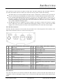
The connectors of the receiver are placed on both sides. One side contains the D/C and Data connectors,
the other side the RF connectors. When you connect the receiver, please consider the following:
The fault relays at J1 are Photo MOS solid state circuits. In fault state or while the unit is powered off
they are in hi-Z state (several MOhms). A resistance below 25 Ohms indicates that the function is OK.
J3 is a standard 9-pin RS232 (DCE) connector. You may use a direct 9-pin cable to connect a PC to
the beacon receiver. The RTS/CTS and the DTR/DSR lines are bridged in the receiver to simulate
hardware handshaking. They need however not to be connected, if you want to use a 3 wire cable. J3
also contains the RS422 streaming output.
The RF input J5 may be configured to power a LNB. If you intend to connect the receiver to a signal
source which may not be able to withstand the LNB supply voltage, be sure to switch off the LNB
supply at the receiver by means of remote control interface before you connect the receiver input!
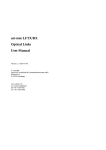
D/C and data connectors
The D/C and data connectors of the receiver all are located at one of the side panels of the enclosure. The
figures below illustrate location of connectors and the pin out.
J3 pin
no.
J4
RS232 serial interface, DCE, (SUB-D J1 pin
9P socket)
no.
Power supply and alarm contacts
(SUB-D 9P pin)
1
RS422 Streaming output (+)
1
Power supply +24V
2
TxD (output)
2
Power supply +24V
3
RxD (input)
3
not connected
4
internally bridged to pin 6
4
GND
5
GND
5
GND
6
internally bridged to pin 4
6
Fault relay (120V D/C, 100mA max.)
7
internally bridged to pin 8
7
Fault relay
8
internally bridged to pin 7
8
Level fault relay (120V D/C, 100mA
max.)
9
RS422 Streaming output (-)
9
Level fault relay
Beacon level 0..10V (SMA female)
J2
Ethernet 10Base-T, (RJ45)
not used by the LBRX-1MT
RF connectors
The other side panel of the enclosure contains the RF connectors. These are the RF input which may be
configured to inject a LNB supply voltage of 14 or 18 Volts and the RF output which loops through the input
signal.
(C) 2013, SatService GmbH
www.satnms.com
LBRX-1MT-UM-1301 Page 6/21
SatService
Gesellschaft für Kommunikationssysteme mbH
J5 RF Input (SMA female)
J6 RF Output (SMA female)
2.4 Configuring the Receiver
This chapter gives a short overview about some configuration parameters you want to set after you have
installed the sat-nms LBRX beacon receiver. A complete reference of all available setup parameters is given
in chapter 3 Operation / Remote Control.
To verify / set these parameters prior to the installation of the LBRX-1MT, connect the device to a 24V
power supply and to the COM port of a PC by means of a straight-through 9-pin cable. Start you favourite
terminal emulation program and configure the COM port to 19200-N-8-1.
LNB LO Frequencies
The receiver lets you enter the receiver frequency in terms of the RF frequency at the antenna. The receiver
is prepared to manage separate LO frequencies for a lower and a upper band LNB. The setup parameter
you have to configure are:
High band LO frequency, Query: lof2=?
Low band LO frequency, Query: lof1=?
Band edge, Query: edge=?
If your antenna provides only one single conversion frequency, set this value for both LO frequency
parameters and set the band edge to zero. The receiver also supports applications where the LO frequency is
above RF receive frequency. In this case, enter the LO frequencies as negative values.
LNB Supply Voltage
The receiver is able to supply a LNB through the L-band cable. Set the 'LNB voltage' parameter to the
appropriate value. The special value 'AUTO' enables the LNB supply voltage and switches between 14V
and 18V following the receive polarisation you set. Query: lnbv=?. To switch off the LNB supply voltage,
type lnbv=OFF.
LNB Frequency Band Selection
For antennas switching between frequency bands with a 22kHz tone controlled switch the receiver is able to
generate the 22kHz tone either permanently or automatically depending on the receive frequency. Set the
'22kHz tone' parameter to one of the settings OFF, ON or AUTO. Query: ln22=?
2.5 Mechanical installation
(C) 2013, SatService GmbH
www.satnms.com
LBRX-1MT-UM-1301 Page 7/21
SatService
Gesellschaft für Kommunikationssysteme mbH
The receiver enclosure is DIN rail mountable. Hence simply snap the receiver on to the rail to fix it. For
plain wall mount, fix a 270 mm piece of DIN rail at the wall with at least two screws and lock the receiver
on this.
When planning the mechanical installation of the receiver, please consider that the connectors are placed at
the front sides of the enclosure. Depending on the flexibility of the cables you are going to use, you will
require about 10 centimetres space for cabling on both sides of the receiver.
(C) 2013, SatService GmbH
www.satnms.com
LBRX-1MT-UM-1301 Page 8/21
SatService
Gesellschaft für Kommunikationssysteme mbH
3 Operation / Remote Control
The LBRX-1MT beacon receiver does not provide any local control interface. It is controlled remotely
through a serial RS232 interface. At this interface, the receiver provides two different protocol modes:
After power on, the receiver wakes up in terminal / ASCII protocol mode. In this protocol mode, commands
may be entered and terminated by a carriage return character. The receiver processes the command and
returns the response, terminated by a CR/LF pair. The terminal / ASCII protocol mode is suitable to
configure the receiver manually by means of a terminal program like the "Hyper-terminal" coming with the
Microsoft Windows operating system. Due to the lack of any checksum protection, the ASCII protocol is
not recommended if the receiver is to be controlled by a M&C computer.
For computer controlled applications, the receiver provides a framed protocol. This protocol implements a
checksum protection which ensures that only correctly transferred messages are processed. The receiver
automatically detects if it gets accessed through the framed protocol and subsequently disables the the
terminal / ASCII protocol until it gets switched off. Chapter "3.2 Framed Protocol" describes this protocol
mode in-depth.
Regardless of the protocol mode, the RS232 interface always operates at 19200 baud, no parity, 8 data bits,
one stop bit. To connect the receiver to a computer's (9-pin) RS232 port you need an off the shelf straightthrough male to female D-SUB9 cable. For installations, a 3-wire cable (pins 2,3 and 5) is sufficient.
A special feature of the sat-nms LBRX-1MT beacon receiver is the RS422 streaming output port, offering
the transmission of the measured beacon level at the full measurement rate with a minimum protocol
overhead. The data format used by this port is described in chapter "3.3 RS422 streaming interface"
3.1 Command syntax
The beacon receiver knows a number of parameters, each identified by a parameter name. The following
rules apply to both protocol variants. With the terminal protocol, commands or queries have to be terminated
by a carriage return character. With the framed protocol, they have to be enclosed by a valid protocol frame
(without carriage return).
To set a certain parameter to a new value, a message:
name=value
has to be sent to the receiver. The receiver interprets this command, checks the range of value, sets the
internal parameter and then answers:
name=value
The value in the reply is the value actually recognised by the beacon receiver. For instance, if the requested
value was out of range, the replied (and internally used) value is limited to the applicable minimum or
maximum.
To read a parameter from the receiver, instead of a new parameter value a question mark is sent:
name=?
The receiver replies the actual value in a complete message:
name=value
(C) 2013, SatService GmbH
www.satnms.com
LBRX-1MT-UM-1301 Page 9/21
SatService
Gesellschaft für Kommunikationssysteme mbH
A complete list of the parameter the beacon receiver knows is shown later in this document in chapter "3.4
Parameter list". Below, some common rules applying to the remote control message syntax are summarised.
Parameter names always are of lower case letters, four characters long.
Non-numeric parameter values always are written in upper case.
Numeric (floating point) values may be specified with an arbitrary precision, however the device will
reply only a fixed number of places. The receiver recognises a decimal point ('.'), numbers must not
contain any commas.
There must not be any whitespace in front or after the '=' in a message.
If the command/query is not of the form name=value or name=?, the receiver replies the message ?
SYNTAX.
If the message syntax is OK, but contains an unknown parameter name is used, the reply is ?
UNKNOWN
Numeric parameters are cut to the limits defined for this particular parameter.
Misspelled choice values cause the receiver to set the first value of the choice list.
Assigning a value to a read-only parameter will cause no fault, however the beacon receiver will
overwrite this parameter immediately or some seconds later with the actual value.
3.2 Framed Protocol
For computer based remote control from a monitoring & control application, the LBRX-1MT provides a
framed protocol with start/stop characters and checksum. With the framed protocol, the receiver expects
each message to be packed into a frame as described below.
char # example description
1
{
start character, always '{'
2
A
device address, always A
3
l
first character of the message body
.
e
message body ...
.
v
..
.
l
..
.
=
..
n-1
?
last character of the message body
n
}
end character, always '}'
n+1
.
checksum
Responses of the receiver are packed the same way. The checksum byte is calculated using an algorithm as
implemented by the following formula:
This protocol type is known as MOD95- or Miteq protocol . The receiver also packs it's reply in a protocol
frame as described above. incomplete frames, checksum errors or address mismatches let the receiver ignore
the message. The time between the characters of a message must be less than 5 seconds or the receiver will
treat the message as incomplete.
The receiver automatically detects if it gets accessed through the framed protocol and subsequently disables
(C) 2013, SatService GmbH
www.satnms.com
LBRX-1MT-UM-1301 Page 10/21
SatService
Gesellschaft für Kommunikationssysteme mbH
the the terminal / ASCII protocol. This means in particular: After one start character ({) of the framed
protocol has been received, the device switches to framed protocol mode and subsequently ignores every
input which is not packed in a valid protocol frame. To return to the terminal / ASCII protocol mode, switch
off the receiver and switch it on again.
3.3 RS422 streaming interface
The RS422 streaming interface is a unique feature of the sat-nms LBRX-1MT beacon receiver. The
interface reports the measured value in a compressed binary format at the full measurement rate of the
receiver (1000 values per second).
The RS422 streaming interface sends each level value as a 2-byte message at 38400 baud, no parity, one
stop bit. In this message, the beacon level is contained as a 14 bit unsigned integer value showing the
negative beacon level [dBm] in steps if 0.01 dB:
level [14-bit-integer] = - beacon-level [dBm] * 100
The 14 bit value coded this way is capable to represent levels in the range -163.83 .. 0.00 dBm. At the
interface, it gets coded into two bytes, each containing 7 bits of the value and one bit to mark the high / low
byte of the value.
1st Message Byte
bit-no
description
7 (msb) always 1, marks the 1st message byte
6
bit 13 (msb) of the level value
5
bit 12 of the level value
4
bit 11 of the level value
3
bit 10 of the level value
2
bit 9 of the level value
1
bit 8 of the level value
0 (lsb)
bit 7 of the level value
2nd Message Byte
bit-no
description
7 (msb) always 0, marks the 2nd message byte
6
bit 6 of the level value
5
bit 5 of the level value
4
bit 4 of the level value
3
bit 3 of the level value
2
bit 2 of the level value
1
bit 1 of the level value
0 (lsb)
bit 1 (lsb) of the level value
The following C-code example explains how to retrieve the level value from the binary data received from
(C) 2013, SatService GmbH
www.satnms.com
LBRX-1MT-UM-1301 Page 11/21
SatService
Gesellschaft für Kommunikationssysteme mbH
the RS422 streaming output port of the sat-nms LBRX-1MT:
double get_lbrx_level() {
unsigned char c;
unsigned val;
double level;
while (1) {
c = get_byte_from_lbrx();
if (c & 0x80) {
val = c & 0x7f;
c = get_byte_from_lbrx();
if ((c & 0x80)==0) {
val = (val << 7) | c;
return - (val / 100.0);
}
}
}
}
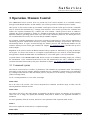
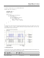
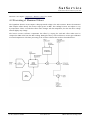
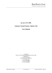
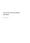
The diagram shown below illustrates the RS422 signal timing and the polarity of the signals at pins 1 and 9
of the M&C connector. To ensure a reliable communication through the RS422 interface, the receive side
should terminate the line with 120 Ohms.
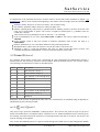
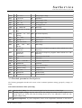
3.4 Parameter list
The table below shows the complete (alphabetical) list of M&C parameters the beacon receiver knows. For
each parameter the valid range and a short description is given.
name
adcv
range
unit
description
r/o 0 65535
Raw ADC value
(C) 2013, SatService GmbH
www.satnms.com
LBRX-1MT-UM-1301 Page 12/21
SatService
Gesellschaft für Kommunikationssysteme mbH
adcv
r/o 0 65535
aout
r/o 0.0 .. 10.0
attn
Raw ADC value
V
Analog output voltage
0 10 20 30
dB
Attenuation
daco
-200 .. 0
dB
Analog output offset
dacs
-5.0 .. 5.0
V/dB Analog output scale
dflt
r/o OK FAULT
D/C supply fault
edge
0 .. 19000.000
MHz Band edge
fltr
0 0.1 0.5 1 5 10 50 Hz
100
freq
depends
settings
on
Post detector filter
LO MHz RF receive frequency
lbfr
r/o 950 .. 2050
MHz L-Band receive frequency
levl
r/o -999.99 .. 0
dBm
Beacon level
ln22
OFF ON AUTO
22kHz Tone
lnbv
OFF
14V
AUTO
lof1
-19000.000
19000.000
.. MHz Low band LO frequency (negative values indicate LO > RF
frequency)
lof2
-19000.000
19000.000
.. MHz High band LO frequency (negative values indicate LO > RF
frequency)
msbw
6 12 30 100
rxpl
HV
Polarisation
scmp
-10.0 .. + 10.0 dB
Spectrum compensation
18V
LNB voltage
kHz
Measurement bandwidth
sflt
r/o OK FAULT
Synth fault
srno
r/o character string
Device serial number
sver
r/o character string
Software version
temp
r/o -40 .. 120
tflt
r/o OK FAULT
thrh
-999.99 .. 0
°C
Temperature
Threshold fault
dBm
Alarm threshold
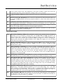
3.5 Detailed parameter descriptions
The following paragraphs describe each remote control command parameter setting, grouped by category of
usage.
State and measurement values (read-only)
levl
(Receive level, dBm) This is the measured signal level at the receiver's L-band input.
adcv
(Analog output voltage, V) This value shows the voltage the receiver actually outputs at it's
analog output port. Please note that the reading shown here is not calibrated to match the true
output voltage exactly.
temp (Board temperature, °C) The temperature shown is the temperature measured on the beacon
(C) 2013, SatService GmbH
www.satnms.com
LBRX-1MT-UM-1301 Page 13/21
SatService
Gesellschaft für Kommunikationssysteme mbH
receiver printed circuit board. The temperature at this place normally is about 20°C above the
environment temperature, hence temperature readings at 65°C are not unusual.
lbfr
(L-Band Frequency, MHz) Querying this parameter returns the L-Band frequency the receiver is
tuned to.
tflt
(Receive Level Fault, OK/FAULT) If the receive level falls below the alarm threshold which can
be set with the thrh parameter, the receiver responds 'FAULT' or 'OK' if if the level is above the
threshold.
sflt
(Synthesiser Lock Fault, OK/FAULT) If one of the PLL synthesisers in the receiver does not
lock, this parameter reads 'FAULT'. This happens if you tune the frequency out of it's valid range.
dflt
(D/C Supply Fault, OK/FAULT) The receiver monitors it's internal supply voltages. If one of
them is out of range, 'FAULT' is reported when querying this parameter.
adcv
(Raw ADC Level, decimal 0..65535) Reading this parameter returns the raw A/D converter
reading with no calibration or filtering applied.
Measurement settings
freq
(RF receive frequency, MHz) This parameter controls the receiver's receive frequency.
Depending on the LO frequency settings made with the lof1, lof2 and edge parameters, the
frequency value either is expressed as the RF receiver frequency or the L-band frequency at the
receiver's input. If the '22 kHz Tone' parameter (ln22) is configured as 'AUTO', changing the
frequency also will switch the 22kHz modulation on the LNB power supply on or off, according
to the band of the frequency setting
rxpl
(Receive polarisation, H/V) If the 'LNB voltage' parameter (lnbv) is set to 'AUTO', the receive
polarisation may be set with this parameter. If lnbv is not set to 'AUTO', changing the rxpl
parameter has no effect.
attn
(Input attenuation, 0/10/20/30) The receiver provides a switchable input attenuator which lets
you adjust the input level in 10 dB steps. This is specially useful with large Antennas pointing to a
satellite which generates a high flux density. With the attenuator you may adjust the input level in
order to avoid saturation effects in the receiver. All input attenuator steps are calibrated, the
attenuation values are taken into account for the displayed receive level. Available attenuator
settings are 0, 10, 20 and 30 dB.
msbw (Measurement bandwidth, 6/12/30/100) The receiver provides four different measurement
bandwidth filters (6, 12, 30 and 100 kHz). The 30 kHz filter is suitable for majority of cases.
fltr
(Post detector filter, 0/0.1/0.5/1/5/10/50/100 The receiver's software applies a low pass filter to
the measured level values. This is much like the video filter at a spectrum analyser. Available
bandwidth settings for this filter are 100 Hz to 0.1 Hz in 1/5 steps. Lower bandwidth settings
make the reading more stable, reduce the fluctuation. Please keep in mind, it will take a noticeable
time until the level reading settles after an input level change with a very low bandwidth setting.
Setting fltr=0 disables the low pass filter completely.
scmp
(Spectrum compensation, dB) With this parameter set to 0.0, the receiver's level reading is
calibrated for a C/W signal. With this parameter you can set an offset (range -10.0 .. +10.0 dB)
which is added to the measurement reading in order to compensate for differences arising from
the received signal's spectrum shape. The spectrum compensation offset applies to the value of
the levl parameter and to level sent through the RS422 streaming output as well.
thrh
(Fault threshold, dBm With this parameter you set the level fault threshold. If the measured
level falls below this value, the receiver states a receive level fault. To disable the level fault, set
the threshold to a very low value, e.g. -199 dBm.
(C) 2013, SatService GmbH
www.satnms.com
LBRX-1MT-UM-1301 Page 14/21
SatService
Gesellschaft für Kommunikationssysteme mbH
Analog output configuration
dacs
(Analog output scale) This parameter defines the slope of the receiver's voltage output in V/dB.
The output voltage has a range of 0 .. 10 V. Setting this parameter to 0.25V/dB lets the analog
output cover a dynamic range of 40 dB. The scale value may be negative, which lets the output
voltage fall for rising input level values.
daco (Analog output offset) This parameter defines, which input level gives 0V output. Example:
setting dacs=0.25 and daco=-90 programs the analog output to read 0V at -90 dBm beacon level
and +10V at -50 dBm.
LNB configuration
lnbv (LNB voltage, OFF/14V/18V/AUTO) This parameter controls the LNB supply voltage provided
by the receiver at it's input connector. The following settings are available:
OFF The D/C voltage is completely switched off.
14V
The LNB supply voltage is 14V
18V
The LNB supply voltage is 18V
AUTO The LNB supply voltage is switched on, the voltage depends on the 'Polarisation'
parameter (rxpl). The voltage is
14V for vertical polarisation,
18V for horizontal polarisation.
ln22
(22KHz tone, OFF/ON/AUTO) This parameter controls the presence of a 22 kHz tone on the
LNB supply voltage. The following settings are available:
OFF The 22 kHz tone is switched OFF.
ON
The 22 kHz tone is switched ON.
AUTO The receiver automatically enables the 22 kHz tone depending on the receive frequency
set. The tone is
switched OFF for frequencies below the band edge,
switched ON for frequencies above the band edge.
The band edge is set with the 'Band edge' parameter below.
lof1
(Low band LO frequency, MHz) This parameter sets the conversion (LO) frequency frequency
for the lower frequency band LNC. Common values for this frequency are 10000 MHz or 9750
MHz for consumer antennas. Set this value to zero if you intend to set the receive frequency in
terms of L-band frequency. If the LO is above above the receive frequency (e.g. for a C-Band
application) enter the LO frequency as a negative value.
lof2
(High band LO frequency, MHz) This parameter sets the conversion (LO) frequency frequency
for the upper frequency band LNC. Common values for this frequency are 11300 MHz or 10600
MHz for consumer antennas. Set this value to zero if you intend to set the receive frequency in
terms of L-band frequency. Normally the receiver assumes, that the LO is below the RF receive
frequency as this is common for Ku-band LNCs. If the LO is above above the receive frequency
(e.g. for a C-Band application) enter the LO frequency as a negative value.
edge (Band edge, MHz) This parameter defines the frequency threshold where to switch between the
frequency bands.
Miscellaneous (read-only)
srno (Serial number) Querying this parameter returns the serial number of this device.
(C) 2013, SatService GmbH
www.satnms.com
LBRX-1MT-UM-1301 Page 15/21
SatService
Gesellschaft für Kommunikationssysteme mbH
sver
(Software version) Querying this parameter returns the software version installed.
(C) 2013, SatService GmbH
www.satnms.com
LBRX-1MT-UM-1301 Page 16/21
SatService
Gesellschaft für Kommunikationssysteme mbH
4 Theory of Operation
The beacon RX receives a satellite beacon signal which is down-converted to L-Band by a PLL stabilised
Low Noise Converter (LNC) at its L-band interface input. The beacon RX does not demodulate any satellite
because the satellite signals are sometimes CW signals but also very often modulated in FM or BPSK form.
Due to this fact the best implementation is a non-coherent receiver which measures the input level in a user
selectable defined bandwidth and provides this as a dB-linear and calibrated analogue output voltage and
digital information.
The level output is provided by three different and parallel available interface types: The RS232 interface
providing a bi-directional monitor and control protocol, the measurement data streaming output (RS422) or
the analog voltage output. The sat-nms beacon receiver is controlled remotely by a monitoring and control
application through the RS232 port. The RS422 streaming output sends the measured level at the full
measurement rate of the receiver with a minimal protocol overhead.
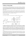
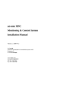
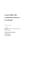
4.1 Receiver Design
The following block diagram shows the functional blocks of the sat-nms L-Band Beacon Receiver.
The L-band input signal is applied to the SMA connector X1. The receive frequency range is from 950MHz
to 2050MHz. A small portion of the input signal is coupled out of the main signal flow, the coupling is
compensated by a small amplifier and this signal is provided as a L-band test output signal with the same
output level at the L-Band test output SMA connector with the same power level for test and measurement
purposes. The L-band signal is filtered within a 950 to 2050MHz filter and then attenuated by a
programmable attenuator in steps of 0dB, 10dB, 20dB or 30dB. After this programmable attenuator a first
amplifier with approximately 20dB of gain and a noise figure of 3.5dB amplifies the signal for the first down
conversion in a 13dBm mixer. This mixer converts the L-band input signal to the first IF of 765MHz by use
of a PLL frequency synthesiser. This mixer is highly linear and determines the overall dynamic range of the
system.
The 765MHz signal is then filtered by use of two 3-pol. ceramic filters which attenuates the out of receive
channel signals. After these two filter stages the 765MHz signal is converted by a second mixer to a 70MHz
IF by use of the fractional-N synthesiser. Direct behind the mixer a SAW filter with approximately 300kHz
bandwidth is used to filter the 70MHz signal. This filter has a very high Q so that only frequencies inside the
bandwidth will be fed to the last mixer circuit.
(C) 2013, SatService GmbH
www.satnms.com
LBRX-1MT-UM-1301 Page 17/21
SatService
Gesellschaft für Kommunikationssysteme mbH
This mixer converts the 70MHz IF into the final 455kHz IF by use of 1/10 the frequency of the fractionalN synthesiser. The 455kHz IF signal is the fed into a one of four analog multiplexer circuit. Via the internal
micro controller the appropriate bandwidth of 6, 12 30 and 100KHz is selectable. The 6, 12 and 30KHz
filters are ceramic filters the 100kHz filter is due to the high relative bandwidth a discrete filter with inductors
and capacitors. OP-amps behind the filters are used to match the filters with the appropriate impedance and
are used to provide almost the same level as at the multiplexer input. In a last gain stage the 455kHz signal is
amplified to the appropriate level for the level detector.
The signal level is measured with a logarithmic amplifier. This level detector has a very high dynamic range
and is also very linear. Output of the level detector is a D/C voltage proportional to the L-band input power.
This voltage is converted into a 16bit digital word by an analogue to digital converter with 16bit resolution.
A on board temperature sensor gives the beacon receiver M&C board the knowledge about the temperature
on the RF circuit board and allows fro temperature compensation.
D/C-input to the beacon receiver is +24V/0.5A provided by the M&C board.
There are two D/C-D/C converters on the board to convert the +24V D/C into +6V for the analog +5V
supply and the digital +3.3V / +5V. The digital D/C voltage regulator provides a DC_ERROR signal which
can be read back to the M&C board.
The 2nd D/C-converter is used for the LNB supply which can be programmed either to 14V or 18V.
Furthermore this LNB voltage can be modulated by the Diseq_22kHz signal to provide a DiseqC interface.
The DiseqC interface is not implemented in the first design stage but the hardware basis is given with this
circuit design and the real DiseqC implementation is later on a question of software in the micro-controller
on the beacon receiver M&C board. At the moment only a 22KHz signal is generated if necessary
In cases where no LNB supply is needed the D/C converter can be switched off by the LNC_ON signal.
In order to reduce interference from the micro-controller to the RF part and also to reduce cost on the PC
board production the circuit for the monitoring and control of the L-Band beacon receiver is designed on a
second printed circuit board.
The main interface to the beacon receiver RF board is via the SPI interface. This means that the analog to
digital converter, the temperature sensor and also all monitoring and alarm input and output ports are placed
on the RF board and the digital information is routed via the SPI bus to the M&C board and its microcontroller.
In addition to that the following interface is provided, the output of the logarithmic detector provides a
analog output voltage which can be used via two interfaces:
Analog output
Output via 16bit analog to digital converter
The analog output voltage is provided to allow the receiver to interface with other manufacturers antenna
control units. The analogue output voltage is generated in the micro-controller in digital form. This does
have the big advantage that all temperature, linearity and slope compensation is also valid for the analogue
output voltage. Also the slope in dB/V and the input level which generates 0V analogue output voltage can
be set via the web browser interface. Via this connector other vendors antenna control units can receive their
beacon level input signal as analog voltage connected to their analog to digital converter in the ACU. The
SMA connector was selected due to space reasons, as a BNC did not fit on the interface side of the L-Band
beacon receiver housing.
This micro-controller controls also the synthesiser and the other hardware selections like bandwidth control.
The micro-controller communicates to the to the 'outside world' through two serial communication
(C) 2013, SatService GmbH
www.satnms.com
LBRX-1MT-UM-1301 Page 18/21
SatService
Gesellschaft für Kommunikationssysteme mbH
interfaces. See chapter '3 Operation / Remote Control' for details.
4.2 Processing of Measured Values
The logarithmic detector circuit outputs a dB-proportional voltage to the A/D converter. Hence the measured
ADC samples reflect directly the receiver's input power in dBm. The readings however are subject to vary
by temperature. There is an absolute offset which changes with the temperature, but also the dB to voltage
relation slightly may change.
The beacon receiver software compensates this effect by varying the scale and offset values used to
compute the dBm value from the ADC reading. During the factory tests each beacon receiver gets calibrated
at several temperatures. The data processing of the receiver software then works as described below:
(C) 2013, SatService GmbH
www.satnms.com
LBRX-1MT-UM-1301 Page 19/21
SatService
Gesellschaft für Kommunikationssysteme mbH
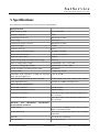
5 Specifications
The table below summarises the beacon receiver's specifications:
RF Specification
Input frequency range
950 to 2050 MHz
Frequency Step Size
1 KHz
L-Band Input Connector
SMA female 50 Ohm
LNC voltage
OFF/14/18V
L-Band Test Output Connector
SMA female 50 Ohm
Input Noise Figure
< 10dB
Frequency accuracy
1*E-6
Input Level measurement range
-40 dBm to -80 dBm
Measurement bandwidths
6, 12, 30 and 100 KHz
Minimum C/N0 (6kHz)
45 dBHz
Output Voltage range of analogue AGC voltage
0V to 10V
Slope of analog output voltage
programmable, -5.0 .. +5.0 V/dB
0V point of analog output voltage
programmable, -200 to 0 dBm
Output Connector for analog output voltage
SMA female
Linearity failure
+/-1dB in any 10 dB
Switchable input attenuator to adapt the dynamic 0, 10, 20, 30 dB
range and input signal level
Video bandwidth selectable by micro controller
0.1 Hz, 0.5 Hz, 1 Hz, 5 Hz, 10Hz, 50 Hz, 100 Hz
Large signal behaviour
no impact at -35dBm total input power
M&C Interface Specification
RS232 M&C Interface
D-SUB 9 female
RS422 level information TX-only
D-SUB 9 female
Summary fault indication
Photo MOS relay contact D-SUB 9 male (120 V
D/C, 100 mA)
Level alarm indication
Photo MOS relay contact D-SUB 9 male (120 V
D/C, 100 mA)
Electrical
and
Mechanical
Environmental conditions
Specification,
Supply Voltage
22 V to 28 V unregulated D/C (25V for 2050
MHz) 0.35A without LNB
Temperature range
-25° to +55° C operational, -40° to +70° C storage
temperature
Humidity
up to 90% non condensing
DIN rail module
270 x 105 x 50 mm
(C) 2013, SatService GmbH
www.satnms.com
LBRX-1MT-UM-1301 Page 20/21
SatService
Gesellschaft für Kommunikationssysteme mbH
Weight
(C) 2013, SatService GmbH
1,5 kg
www.satnms.com
LBRX-1MT-UM-1301 Page 21/21