1
sat-nms IO-FEP
I/O Frontend Processor
User Manual
Version 2.7 / 2014-06-18
© Copyright
SatService Gesellschaft für Kommunikatiosnsysteme mbH
Hardstrasse 9
D-78256 Steisslingen
www.satnms.com
www.satservciegmbh.de
Tel +49 7738 97003
Fax +49 7738 97005
SatService
Gesellschaft für Kommunikationssysteme mbH
Table Of Contents
Table Of Contents ................................................................................................................................. 1
1 Introduction ........................................................................................................................................ 2
2 Installation ......................................................................................................................................... 5
2.1 Safety Instructions ........................................................................................................................ 5
2.2 Setting the IP Address .................................................................................................................. 5
2.3 Connecting the IO-FEP ................................................................................................................. 7
2.4 Configuring the sat-nms IO-FEP .................................................................................................. 12
2.5 Mechanical installation ............................................................................................................... 15
3 Operation ......................................................................................................................................... 16
3.1 The Web-based User Interface ................................................................................................... 16
3.2 Displayed State .......................................................................................................................... 16
3.3 Output Circuit / WG Switch Operation ........................................................................................ 18
3.4 Installation Parameters ............................................................................................................... 18
3.4.1 General Setup .......................................................................................................................... 18
3.4.2 Output Circuits ........................................................................................................................ 20
3.4.3 WG Switches .......................................................................................................................... 21
3.4.4 Input Circuits ........................................................................................................................... 23
3.4.5 Temperature Sensors ............................................................................................................... 24
3.4.6 Protection ................................................................................................................................ 24
3.5 Event Log .................................................................................................................................. 26
4 Remote Control ................................................................................................................................ 26
4.1 General command syntax ............................................................................................................ 27
4.2 The TCP/IP remote control interface ........................................................................................... 28
4.3 The RS232 remote control interface ............................................................................................ 28
4.5 SNMP Control ............................................................................................................................ 29
4.4 Parameter list ............................................................................................................................. 29
5 Connector Reference ........................................................................................................................ 32
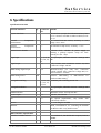
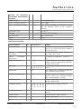
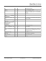
6 Specifications ................................................................................................................................... 44
(C) 2015, SatService GmbH
www.satnms.com
IO-FEP-UM-1505 Page 1/47
SatService
Gesellschaft für Kommunikationssysteme mbH
(C) 2015, SatService GmbH
www.satnms.com
IO-FEP-UM-1505 Page 2/47
SatService
Gesellschaft für Kommunikationssysteme mbH
1 Introduction
The IO-FEP manufactured by SatService GmbH is a frontend-processor which is especially designed for
satellite ground stations. It allows to supervise potential-free (alarm-) contacts, to switch external items, to
measure different temperatures, to switch and control waveguide- or coaxial-switches, it is possible to assign
the inhibit-contacts of the waveguide-switches to up to 10 connected HPAs and additionally it is possible to
realize different 1 to n redundancy Systems.
The IO-FEP is available in two different versions: The IO-FEP is the standard version, the IO-FEP-E is the
extended version with a larger quantity of digital input and waveguide-switch interfaces. The IO-FEP
supervises altogether 32 (IO-FEP-E: 48) digital-inputs via optocoupler. Up to 4 different temperatures can be
measured with external PT1000 sensors. To switch external units, the IO-FEP has 6 potential-free relay
outputs and 10 photomos-relay outputs. The 8 (IO-FEP-E: 16) waveguide-switches that can be controlled
by the IO-FEP are supervised by their position and switching state (for muting the HPA in the switching
moment). Also the IO-FEP contains an inhibit matrix, that allows to allocate different inhibit signals of
waveguide-switches on different HPAs. So it is possible to mute up to 10 HPAs by up to 8 (IO-FEP-E: 16)
waveguide-switches. The IO-FEP also contains a software-inhibit matrix. If the used waveguide-switches are
not equipped with an inhibit-contact, nevertheless the connected HPA's can automatically be muted by
software.
The data output is provided by 2 different and parallel available interface types: a HTTP Web Interface via
an internal Web Server, and a RS232 interface. The sat-nms IO-FEP is controlled remotely by a monitoring
and control application through the TCP/IP interface. The IO-FEP implements the protocols HTTP (for
both, the user interface and for remote control) and SNMP. The sat-nms IO-FEP MIB may be downloaded
from the IO-FEP itself using FTP.
This document is the user manual provided with the sat-nms IO-FEP It contains all necessary information
how to install, setup and operate the processor. The user manual is available as a printed document and for
online reading on the IO-FEP itself as well.
The paragraphs below give a short overview to the contents of this manual.
Installation: The installation chapter guides through the installation and setup of the sat-nms IO-FEP. It
describes the mechanical concept of the IO-FEP box and the assignment of the connectors. Finally you
learn in this chapter how to set the IO-FEP's IP address, which is a essential precondition to operate
the IO-FEP by means of a web browser. This section is available in the printed version only.
Operation: The sat-nms IO-FEP is operated using a standard web browser like the Internet-Explorer
on MS Windows based computers. The user interface design is straight forward and clearly structured.
Operating the IO-FEP is mostly self-explanatory. Nevertheless, the 'Operation' chapter outlines the map
of web pages which make up the IO-FEP user interface and elaborately describes the meaning of each
alterable parameter.
Remote Control: T he sat-nms IO-FEP provides a versatile remote control interface. A monitoring &
control software may fully operate the IO-FEP either through a TCP/IP network connection or
through the RS232 interface of the IO-FEP. This chapter describes the communication protocol used
for remote control and lists all parameters accessible through the remote interface.
Connector Reference: This chapter provides a comprehensive reference of the sat-nms IO-FEP' input /
output connectors.
Specifications: At the end of the document, the specifications applicable to the sat-nms IO-FEP are
summarized in this chapter.
(C) 2015, SatService GmbH
www.satnms.com
IO-FEP-UM-1505 Page 3/47
SatService
Gesellschaft für Kommunikationssysteme mbH
Version 2.7 / 2013-12-09
Support and Assistance
If you need any assistance regarding our sat-nms IO-FEP, don't hesitate to contact us. We would be pleased
to help you by answering your questions.
SatService GmbH phone +49 7738 9700-3 or -4
Hardstrasse 9
fax +49 7738 97005
78256 Steisslingen www.satnms.com
- Germany -
(C) 2015, SatService GmbH
www.satnms.com
IO-FEP-UM-1505 Page 4/47
SatService
Gesellschaft für Kommunikationssysteme mbH
2 Installation
This chapter describes how to install the sat-nms IO-FEP. You find a guide how to connect, configure and
mechanically mount the IO-FEP below.
Before you start, please first read the Safety Instructions chapter below. It contains some important
recommendations to prevent damage from the IO-FEP.
Then, we strongly recommend to do a first setup of the IO-FEP on a lab desk before installing it at it's final
location. This is mainly for one reason:
1. To setup the processor's IP parameters, the PC used for configuring and the IO-FEP must either be
connected to the same Ethernet hub or must be connected directly with a crossover cable. The
initialization program does not work through routers intelligent network switches.
Hence, the typical sequence of tasks when putting an sat-nms IO-FEP into operation is as follows:
1.
2.
3.
4.
Read the chapter Safety Instructions
Set the device's IP address
Mechanically mount the device.
Connect the IO-FEP at it's destination environment.
2.1 Safety Instructions
Failure to observe all Warnings and Cautions may result in personnel injury and/or equipment damage not
covered by the warranty.
Follow standard Electrostatic Discharge (ESD) procedures when handling a sat-nms IO-FEP.
Select and apply the appropriate 24V D/C voltage according to the data sheet and documentation
before connecting power.
Before you connect the IO-FEP to another unit, please make sure that the unit to which you connect
can handle the voltage provided by the sat-nms IO-FEP.
The sat-nms IO-FEP can be damaged if the input voltage is higher than the specified maximum value.
Do not connect units that can be damaged by the output voltage of the sat-nms IO-FEP.
In case of a failure do not open the device, you will loose warranty, call SatService GmbH for an
RMA number.
Observe normal safety precautions when operating, servicing, and troubleshooting this equipment.
Take standard safety precautions with hand and/or power tools.
2.2 Setting the IP Address
Before you can operate the IO-FEP, you need to set the processor's IP address. There is a special
configuration program on the documentation CD shipping with the IO-FEP for this purpose. We
recommend to configure the processor's TCP/IP settings before you install the IO-FEP at it's final place. To
configure the IO-FEP, the following equipment is required:
The sat-nms IO-FEP itself
2 24V D/C power supplies (If you want to build a redundancy Power supply, you need 4 24V D/C
power supplies)
A Computer running a Microsoft Windows operating system equipped with CD-ROM drive and
Ethernet network card.
A CAT5 crossover network cable or a Ethernet hub and standard network cables to connect the IO(C) 2015, SatService GmbH
www.satnms.com
IO-FEP-UM-1505 Page 5/47
SatService
Gesellschaft für Kommunikationssysteme mbH
A CAT5 crossover network cable or a Ethernet hub and standard network cables to connect the IOFEP and the computer.
The CD-ROM shipping with the sat-nms IO-FEP.
Setting the IO-FEPs IP parameters now is easily done within a few minutes.
1. First install a network cable between the IO-FEP and your computer. If you have a crossover cable
available, this is very easy: simply put the cable into the network connectors of computer and IO-FEP.
Without a crossover cable, you need to connect both, the computer and the IO-FEP to the same
network hub using two standard network cables. It is essential, that the computer and the IO-FEP are
connected to the same network segment, the configuration program is not able to find the IO-FEP
through routers or network switches.
2. Now power on your computer and connect the IO-FEP to the 24V D/C supply.
3. Insert the CD-ROM into the computer's drive and inspect it's contents through the 'My Computer' icon
on your desktop. Double-click to the 'ChipTool.exe' program in the 'ChipTool' directory.
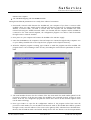
4. When the ChipTool program is running, type CTRL+F to make the program search the IO-FEP. The
program shows a list containing at least one entry describing the actual network parameters of the IOFEP.
5. The serial number shown in the first column of the list, must match the serial number printed on the
processor's enclosure. If the list stays empty, the IO-FEP is not connected properly. If there are more
entries in the list, the configuration program has found other devices in this network segment which
use the same technology.
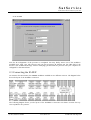
6. Now type CTRL+I to open the IP configuration window of the program. In this form enter the
processor's serial number, it's new IP address and network mask. If the IO-FEP later shall be operated
through a router, enter the address of the router on the gateway field, otherwise leave this field blanc.
Be sure, that the 'DHCP' mark is unchecked. Finally click to the 'Yes' button to set the new parameters
(C) 2015, SatService GmbH
www.satnms.com
IO-FEP-UM-1505 Page 6/47
SatService
Gesellschaft für Kommunikationssysteme mbH
at the IO-FEP
Now the IP configuration of the processor is completed. You may finally want to test if the IO-FEP is
reachable now. Start your web browser and type the processor's IP address into the URL field of the
browser. The IO-FEP should reply with it's main page, provided that the processor and your computer are
configured for the same subnet.
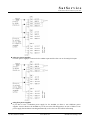
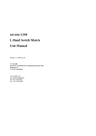
2.3 Connecting the IO-FEP
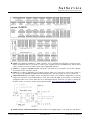
As written in the introduction, the sat-nms IO-FEP is available in two different versions. The diagram below
shows the layout of the IO-FEP's connectors:
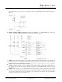
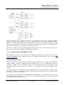
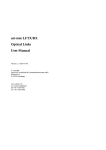
The following diagram shows you the layout of the IO-FEP-E's connectors. For better overview the topview is splitted in two pictures.
(C) 2015, SatService GmbH
www.satnms.com
IO-FEP-UM-1505 Page 7/47
SatService
Gesellschaft für Kommunikationssysteme mbH
CON1 is the Ethernet 100Base-T / RJ45 connector. Use a standard network cable to connect the IOFEP to an Ethernet hub. If you want to connect your computer and the IO-FEP directly without using
a hub, you need a crossover cable for this with swapped RX/TX lines.
CON2 is to supply the sat-nms IO-FEP with power. You need two power packs, one for the +24VDC
and another for the 24V_EXT circuit.
CON3 is to realize a redundant power supply system. When you connect two other power packs on
this connector the sat-nms IO-FEP switches automatically to the other supply in case of current loss.
CON4 and CON5 are the digital outputs via photomos-relays. The standard configuration is, that the
outputs are connected to the inhibit matrix to mute the connected HPAs in the moment of switching a
waveguide switch. You can use them also as normal digital outputs. Therefore you have to change the
Position of JP1...12. How to do this is described in chapter 2.4 configuring the sat-nms IO-FEP
CON6, CON7, CON8 and CON9 are the connectors for digital inputs 1...16. They are only able to
(C) 2015, SatService GmbH
www.satnms.com
IO-FEP-UM-1505 Page 8/47
SatService
Gesellschaft für Kommunikationssysteme mbH
detect potential-free contacts. Never put Voltage to this pins, the sat-nms IO-FEP might be damaged in
this case.
CON10, CON11, CON12 an CON13 connect the waveguide- or coaxial-switches #1...4 that you
want to control here. The pin allocation is the same on all these connectors.
CON14 is the spare power output. If you want to use the 24V_EXT for other units, you can take the
power from here. The maximum continuous current that can be taken from here is 500mA. Never
exceed this limit, the IO-FEP might be damaged.
CON15 is the RS232 and the I2C-bus interface. If you need an adapter cable to connect the sat-nms
IO-FEP via RS232 interface to your computer, call the support center of SatService GmbH. The I²Cbus interface can only be used with a customized software for the sat-nms IO-FEP and is for special
requirements.
CON16 is the connector for the digital outputs switched by relays. COM1 is switched by three relays
to OUT11...13. OUT14, OUT15 and OUT16 are the switched signals of COM4, COM5 and COM6.
The external voltage that has to be switched by the relays may not exceed 24V. The maximum
continuous current that can be switched is 1A.
(C) 2015, SatService GmbH
www.satnms.com
IO-FEP-UM-1505 Page 9/47
SatService
Gesellschaft für Kommunikationssysteme mbH
CON17 the external sensors to measure up to 4 temperatures have to be connected here. You can use
any standard PT1000 type.
CON18, CON19, CON20 and CON21 are the connectors for digital inputs 17...32. They are only
able to detect potential-free contacts. Never put Voltage to this pins, the sat-nms IO-FEP might be
damaged in this case.
CON22, CON23, CON24 and CON25 connect the waveguide- or coaxial-switches #5...8 that you
want to control here. The pin allocation is the same on all these connectors.
the following connectors are only to find on the extended version IO-FEP-E:
CON26, CON27 are the connectors for digital inputs 33...40. They are only able to detect potentialfree contacts. Never put Voltage to this pins, the sat-nms IO-FEP might be damaged in this case.
CON28, CON29, CON30 an CON31 connect the waveguide- or coaxial-switches #9...12 that you
want to control here. The pin allocation is the same on all these connectors.
CON32, CON33 are the connectors for digital inputs 41...48. In the delivery configuration they are
only able to detect potential-free contacts. Never put Voltage to this pins, the sat-nms IO-FEP might be
damaged in this case. If you want to detect a 24V-Signal, have a look at chapter 2.4 configuring the
sat-nms IO-FEP to learn how to configure the digital inputs to be ablte to detect a 24V-Signal.
CON34, CON35, CON36 and CON37 connect the waveguide- or coaxial-switches #13...16 that you
want to control here. The pin allocation is the same on all these connectors.
Power supply
The sat-nms IO-FEP is prepared to use two different 24VDC power supplies: 24VDC is for the controller
and processor circuit. 24V_EXT is used to supply the digital outputs and the waveguide or coaxial switches.
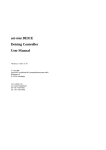
The IO-FEP is prepared for redundant power supply. So it is possible to supply the IO-FEP with one, two or
four power supplies. We strongly recommend to use minimum 2 power supplies to to ensure the maximal
system stability of the IO-FEP The following pictures show you how to connect the power supplies to the
IO-FEP
using only one power supply
in this case 24VDC and 24V_EXT have to be connected to one power supply as you can see in the
following picture
(C) 2015, SatService GmbH
www.satnms.com
IO-FEP-UM-1505 Page 10/47
SatService
Gesellschaft für Kommunikationssysteme mbH
using two power supplies
here one power supply is connected to the 24VDC input and the other one to the 24V_EXT input.
using four power supplies
if you like to have a redundant power supply for the IO-FEP you have to use 4 different power
supplies. Connect them to the IO-FEP as you can see in the following picture. In case of failure of one
power supply the IO-FEP is switching automatically to the other one and will be still running
(C) 2015, SatService GmbH
www.satnms.com
IO-FEP-UM-1505 Page 11/47
SatService
Gesellschaft für Kommunikationssysteme mbH
The power supply for the +24VDC circuit has to have a minimum current load of 150mA (IO-FEP-E:
200mA). The supply for the 24V_EXT has to have a minimum current load of 500mA (IO-FEP-E: 650mA)
plus the current that will be taken from CON14 and the peak current of the biggest waveguide or coaxial
switch to be controlled. Do not exceed the current-limit, in the circuit of 24V_EXT is no fuse implemented!
The maximum peak-current for switching waveguide-switches is 5A.
The fuse for +24VDC circuit is directly beneath the RJ45 connector CON1. In case of damage only put in
there 2A types. Otherwise the sat-nms IO-FEP might be damaged.
2.4 Configuring the sat-nms IO-FEP
This chapter gives a short overview about some configuration parameters you want to set after you have
installed the sat-nms IO-FEP. A complete reference of all available setup parameters is given in chapter 3.4
Installation Parameters.
setting the HPA-mute-matrix
When the connected waveguide switches are equipped with inhibit contacts, it is possible to mute different
connected HPA`s while the waveguide-switch is switching. Every of the 10 DIP-switches DIP1...10
represents one HPA #1...10. The numbers written on every DIP-switch belong to the numbers of the
waveguide switches. When the switch is in position "on" the HPA mutes, when this waveguide switch
switches.
An example: You want to mute HPA #1 when waveguide switch #2 or #4 or #8 changes its condition. Then
you have to configure on the DIP-switch DIP1 the switches #2 and #4 and #8 into the "on"-position. All the
others have to be in the "off"-position.
The extended version IO-FEP-E has additional DIP-switches DIP11...20. With these switches you select
which HPA should mute, when one or more of the waveguide-switches #9...13 is switching. DIP11
represents HPA1, DIP12 HPA2 an so on.
(C) 2015, SatService GmbH
www.satnms.com
IO-FEP-UM-1505 Page 12/47
SatService
Gesellschaft für Kommunikationssysteme mbH
An example: You want to mute HPA #1 when waveguide switch #2 or #9 or #16 changes its condition. Then
you have to configure on the DIP-switch DIP1 the switch #2 and on DIP-switch DIP11 the switch #9 and
#16 into the "on"-position. All the others have to be in the "off"-position.
If the connected waveguide-switch is not equipped with inhibit-contacts, the sat-nms IO-FEP nevertheless
gives you the possibility to mute the HPA in the switching moment by software. Therefore you have to open
the enclosure of the sat-nms IO-FEP and put the Jumper with the number of the HPA in the upper position
(pin 1-2) afterwards you have to configure the software-muting-matrix. How to do this is described in
chapter 3.4 Installation Parameters. The following picture shows, where you can find JP1...10, the jumpers
that define if the inhibit-signal comes from the waveguide-switches or is generated by the processor from the
sat-nms IO-FEP.
For bypassing the inhibit-switching, you find 2 sockets between CON4 and CON5. Use the "jumper
extension" that is shipped with the sat-nms IO-FEP and normal jumpers to bypass the inhibit-outputs.
JP20...24 bypasses the inhibit-signal for HPA #1...5, JP30...34 bypasses the inhibit-signal for HPA#6...10.
The following picture shows you where to find the sockets.
A T T E N T I O N ! when you bypass the inhibit-outputs, the connected HPA(s) will not mute in case of
switching a waveguide-switch! The HPA and the waveguide switch as well might be damaged in this case!
Ensure that no waveguide-switch is switched when the inhibit signal is bypassed!
(C) 2015, SatService GmbH
www.satnms.com
IO-FEP-UM-1505 Page 13/47
SatService
Gesellschaft für Kommunikationssysteme mbH
photomos-relay digital outputs
If you don't have some HPA's to mute or don't need all the mute-outputs, you can use them also as digital
outputs. Therefore you have to open the enclosure of the sat-nms IO-FEP and put all the jumpers of the
outputs, that you want to use this way, in the upper position (pin 1-2). In the second last picture you can
see where to find this Jumpers on the PCB of the sat-nms IO-FEP. Dont´t exceed the continuous current
limit of 130mA and the continuous voltage of 48V DC. Otherwise the sat-nms IO-FEP might be damaged.
If you want to switch inductive loads, don`t forget to add a clamp diode to limit the spike voltages in the
switching moment.
digital inputs DIN41...48 on the IO-FEP-E
On the extended version IO-FEP-E you can select, if you like to detect potential- free on/off-contacts or if
you want to detect a 24V DC Voltage. The factory setting is to detect potential-free contacts, like all the
other digital-inputs. If you want to detect 24V DC voltages, you have to do the following procedure: Open
the IO-FEP-E's enclosure. Top right you find two opto-coupler with black enclosures (all the others are
white). Below these optocouplers you can see two solder-jumpers, as you can see on the following picture.
The left one is for DIN41...44, the right one for DIN45...48. Now open the connection of the solder-jumper
that belongs to the DIN that you want to change. After that close the connection between the middle and the
right-pad (P.F.). The following picture shows you where to find the solder jumpers on the PCB.
The following picture shows how to connect the digital inputs #41...48 in both ways of configuration, and
how it works internally.
(C) 2015, SatService GmbH
www.satnms.com
IO-FEP-UM-1505 Page 14/47
SatService
Gesellschaft für Kommunikationssysteme mbH
2.5 Mechanical installation
The sat-nms IO-FEP enclosure is DIN rail mountable. Hence simply snap the sat-nms IO-FEP on to the rail
to fix it. For plain wall mount, fix a minimum 100 mm piece of DIN rail at the wall with at least two screws
and lock the sat-nms IO-FEP on this. For 19inch rack-mount, SatService GmbH offers a mounting plate.
Call our distribution centre for more informations.
When planning the mechanical installation of the sat-nms IO-FEP, please consider that cables to the satnms IO-FEP have to be fixed on the upper and the under side. So you need some space and something to
fix the cables.
(C) 2015, SatService GmbH
www.satnms.com
IO-FEP-UM-1505 Page 15/47
SatService
Gesellschaft für Kommunikationssysteme mbH
3 Operation
The sat-nms IO-FEP is designed to be controlled over a network link using a standard web browser. This
means in practice, that the user interface to the IO-FEP appears in your browser window after you type in
the IO-FEP's IP address in the address field of the browser program.
Operating the IO-FEP is mostly self-explanatory.
3.1 The Web-based User Interface
After having connected the IO-FEP to a power supply and set the IO-FEPs IP address, you can access the
IO-FEP's user interface. To do this, start your favorite web browser program (Internet Explorer, Netscape
Navigator, Opera or what else Program you prefer). At the address field, where you normally enter the URL
of a web page you want to see, type in the IP address of the sat-nms IO-FEP you want to control.
The IO-FEP shows a web page consisting of a navigation bar at the left side of the browser window and the
actual state display of the IO-FEP in the main part of the window. The readings automatically refresh once a
second.
The navigation bar at the left contains a couple buttons which build the IO-FEP's main menu:
State
This button switches back to the IO-FEPs main page you already see when you connect to the
IO-FEP. This page displays the actual state of the IO-FEP.
Settings By clicking to this button you switch to the 'Settings' page where you can change the position of
the wageguide switches connected to the IO-FEP as well as the state of the outputs which are
available for general purpose.
Setup
Clicking this button expands the navigation bar, making the submenu buttons visible which give
acces to the several sections of the installation / setup dialog. A second click to the 'Setup'
button folds the navigation bar to it's original state.
Event
Log
This button shows the IO-FEP's event log in the main display area (the most recent 25 entries).
The IO-FEP records all input port changes and all switch actuations with a time stamp.
Info
After a mouse click to this button, the IO-FEP shows a table with information like the serial
number of the device or the revision ID and compilation date of the software.
Help
Clicking to this button shows the on-line version of this user manual
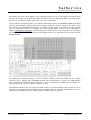
3.2 Displayed State
The 'State' page is the main page of the IO-FEP which shows the actual state of all inputs and outputs. The
page automatically refreshes every second (the refresh interval is configurable at the Setup / General page).
The page shows a 5-column table containing all information about the input / output states, temperature
readings and faults. The page is read-only, to change an output or waveguide switch position go to the
Settings page.
Output Circuits
The output circuits column shows the current state of all outputs which are configured to work as operator
controlled outputs. The outputs 1 to 10 are the photo-MOS output circuits which also may be used as HPA
inhibit outputs. The lines 11 to 16 refer to the relay output circuits provided by the IO-FEP. The following
(C) 2015, SatService GmbH
www.satnms.com
IO-FEP-UM-1505 Page 16/47
SatService
Gesellschaft für Kommunikationssysteme mbH
applies to all output states:
The displayed state ON/OFF is the logical state of the output. By default ON stands for a closed
contact, however, each individual output may be configured to the invers function at the Setup /
Output Circuits page.
Outputs configured as 'UNUSED' neither show a circuit name nor an ON/OFF state.
Outputs configured to act as an HPA inhibit circuits are displayed with a dimmed name, without a
circuit state.
WG Switches
The second column displays the state of the waveguide switches controlled by the IO-FEP. The standard
version provides I/O circuits for 8 switches, the IO-FEP-E for 16 switches.
Each switch may show one of the states 'A', 'B' or 'FLT'. The states are determined from the switches'
positition indication circuits, 'FLT' is shown if both circuits have the same state (unknown position). Table
row referring to switches configured as 'UNUSED' are left empty
Input Circuits
The table columns 3..5 show the state of the input circuits provided by the IO-FEP. The inputs 33 to 48
shown in the last column are only available with the IO-FEP-E.
Inputs configured as 'INPUT' show the states ON or OFF.
Inputs configured as 'ALARM' show the states OK or FLT.
Rows referring to 'UNUSED' inputs are left empty.
The displayed state is the logical state of each input. By default ON/FLT stands for a closed contact,
however, each individual input may be configured to the invers function at the Setup / Input Circuits
page.
The displayed state also takes into account the delay time configured for each individual input. (This
probably will not be visible for short delay times)
Temperature Readings
The IO-FEP displays the internal temperature and the reading of up to four external temperature sensors at
the table field below the output circuits. For each sensor the sensor name, the temperature and an OK/FLT
state is shown. A temperature value is considered 'OK' if the value is inside the limits configured at the
Temperature Sensors page.
Protection Switch State
The IO-FEP up to 8 (the IO-FEP-E up to 16) instances of automatic 1:1 protection / redundancy switching
units. Each protection switch controls the waveguide switch with the same number. Up to 5 alarm inputs
may be assigned to each side of a protection switch at the Setup / Protection page. Two consecutive
protection switches can be coupled to build a 2:1 redundancy circuit.
The following state information is provided for each protection switch unit (unconfigured protection
switches are shown as empty fields, DISABLED instances show the text DISABLED ):
The operation mode 1:1-SW-ONCE/1:1-SW-ALWAYS/2:1-SW-ONCE (see Protection for details)
The chain A fault state (green for OK, red for FAULT)
The switch Position A/B
The chain B fault state (green for OK, red for FAULT)
The SWITCHED flag. This flag is set once the protection switch has actuated the WG switch due to a
fault in the active chain. In 1:1-SW-ONCE mode this prevents the protection switch from further
(C) 2015, SatService GmbH
www.satnms.com
IO-FEP-UM-1505 Page 17/47
SatService
Gesellschaft für Kommunikationssysteme mbH
switching.
2:1 protection switches show the use of the redundant chain (CHAIN-1, CHAIN-2 or NONE) in place
of the switch setting. The fault state of the the redundant chain is shown below this.
Unavailable instances of protection switches are shown shaded with dark background.
3.3 Output Circuit / WG Switch Operation
The page 'Settings' provides a 2-column table which is used to operate output circuits of the IO-FEP and the
waveguide switch connected to it. Like the State page, the table shows the actual position of the outputs /
switches. The display isn't updated automatically, so the displayed state may be outdated if the page is left
open.
Clicking to the state of an output / waveguide switch opens a dialog which provides buttons to change the
switch position. This dialog is password protected, you are required to login in order to change the position
of waveguide switches or output circuits.
Protection switch parameters are shown in the third table column. Each protection switch may be set to
ENABLED or DISABLED. ENABLED means that protection switch is 'hot', it will switch if a fault happens
in the actually selected signal chain. The protection switch may be temporarely DISABLED, e.g. to perform
maintenance tasks at the equipment without triggering the protection switch. For 2:1 protection switches the
enabled state is coupled for both chains.
The function RESET resets the SWITCHED flag of the protection switch (only available if the
SWITCHED flag of the particular protection switch is set).
2:1 protection switches show their loaction setting at the rightmost column. Clicking this lets you set the
redundant chain use explicitely to NONE, CHAIN-1 or CHAIN-2. Note, that while enabled, the 2:1
protection switch does not allow to activate a chain if there is an error pending on it.
3.4 Installation Parameters
The pages accessible through the 'Setup' menu items contain the IO-FEP's installation parameters.
Installation parameters are protected by an administrator password, without a successsful login ad
administrator you may view the configuration settings but you may not change them.
Due to the large number of configuration settings, they are divided into several pages:
General Setup
Contains general configuration parameters like communication interface settings,
passwords etc.
Output Circuits
The usage of the output circuits of the IO-FEP gets configured on this page
WG Switches
The control of the waveguide switches connected to the IO-FEP gets configured on
this page.
Input Circuits
The usage of the input circuits is configured at this page
Temperature
Sensors
The temperature sensors connected to the IO-FEP are configured in this page.
Protection
Protection switch configuration
3.4.1 General Setup
(C) 2015, SatService GmbH
www.satnms.com
IO-FEP-UM-1505 Page 18/47
SatService
Gesellschaft für Kommunikationssysteme mbH
The general setup page provides some general installation settings (section 'General') and the settings of the
IO-FEP's SNMP agent (section 'SNMP Configuration'). The settings are in particular:
General
Display Title
The title entered here is displayed on all pages of the IO-FEP user interface. For
compatibility with older software versions, "State" is treated as an empty title. To remove
an entered title, either enter "State" or a single space character.
Date & Time Click to 'Set Time' in order to set the actual date / time at theIO-FEP's real time clock.
Enter the actual date / time in exactly the format YYYY-MM-DD HH:MM:SS.
NTP Time To make the IO-FEP sync it's internal clock to a NTP time server, set this to the IP
Server 1 IP
address (aaa.bbb.ccc.ddd) of the NTP server. Setting this to 0.0.0.0 disables the NTP
synchronisation (even if time server 2 IP is set).
NTP Time You may define a second (backup) time server IP address with this field. The backup time
Server 2 IP
server is queries if the first servcer is not available. The setting 0.0.0.0 disables the backup
time server interrogation.
NTP Time NTP servers deliver their time stamps in UTC. By setting an offset in this field, you can
Zone Offset
tweak the IO-FEP clock to display local time, even if synced to a NTP server. Entering
"01:00" for example adjusts the clock to CET (Central European Time), "-04:30" to VET
(Venezuelan Standard Time). Beside the the HH:MM notation, the software also accepts
arbitrary values in minutes. The examples above then would read as "60" (CET) or "-270"
(VET). Entering "0" or "00:00" clears the offset, returning the clock to UTC, the same
happens if the offset cannot be parsed by the software.
After changing the time zone, you should clear the event log because old log entries are
not affected by the time zone change.
State
Page The state page by default refreshes automatically every second. The refresh rate may be
Refresh Rate slowed down, setting it to zero disables the automatic refresh completely.
Max.
Concurrent
WG-Switch
Actuations
The IO-FEP is capable to queue / delay waveguide switch actuations in order to protect
weak power supplies from overload. While this is not important if the IO-FEP is
exclusively controlled through the web interface, a monitoring & control computer is
capable to command actuations for all waveguide switches at a time. Set the parameter to
the max. available supply current divided by the current drawn by a single waveguide
switch. Setting the parameter to zero disables the switch actuation queuing.
Serial
I/O The serial interface may be operated either with the MOD-95 / Miteq protocol, using a
Address
device address 'A' to 'G' or with a simple ASCII / terminal protocol (setting 'NONE'). See
chapter 4.3 The RS232 remote control interface for details.
User
Password
Defines the user password (default 'user'), which is required to actuate switches or to set
output circuits of the IO-FEP. An empty password disables the password prompting.
Administrator Defines the administrator password (default 'admin'), which is required to change any
Password
configuration settings. An empty password disables the password prompting.
Reboot
Device
Clicking to REBOOT forces a power up reboot of the IO-FEP (after an inquiry dialog).
You may use this to force the IO-FEP to re-read a SETUP.TXT file you uploaded via
FTP. Please note, that rebooting the IO-FEP interrupts all operation including redundance
switching for about 30 seconds.
SNMP Configuration
(C) 2015, SatService GmbH
www.satnms.com
IO-FEP-UM-1505 Page 19/47
SatService
Gesellschaft für Kommunikationssysteme mbH
Read
Sets the SNMP community string expected for read access. The default is 'public'.
Community
Write
Sets the SNMP community string expected for write access. The default is 'public'.
Community
Trap
Sets the SNMP community string sent with traps. The default is 'public'.
Community
Trap
Destination
IP 1
Enter the trap destination IP address (dotted quad notation) to make the IO-FEP sending
traps by UDP to this host. Setting the parameter to 0.0.0.0 disables the trap generation.
Trap
Destination
IP 2
Enter the trap destination IP address (dotted quad notation) to make the IO-FEP sending
traps by UDP to this host. Setting the parameter to 0.0.0.0 disables the trap generation.
Trap
Destination
IP 3
Enter the trap destination IP address (dotted quad notation) to make the IO-FEP sending
traps by UDP to this host. Setting the parameter to 0.0.0.0 disables the trap generation.
Trap
Destination
IP 4
Enter the trap destination IP address (dotted quad notation) to make the IO-FEP sending
traps by UDP to this host. Setting the parameter to 0.0.0.0 disables the trap generation.
System
Location
The IO-FEP replies to MIB-II sysLocation requests with the text entered at this place.
System
Contact
The IO-FEP replies to MIB-II sysContact requests with the text entered at this place.
Real Time Clock battery backup
The IO-FEP's real time clock is backed up by a goldcap capacitor. The goldcap supplies the RTC chip with
power for several days if the main power is missing. This is the preferred mode of RTC backup for
stationary installations of the IO-FEP.
For applications where the IO-FEP is powered up only occsionally, a lithuim cell may be connected inside
the IO-FEP housing in order to provide a permanent buffering of the clock.
NTP time synchronisation
The IO-FEP may be configured to use one or two NTP time servers as reference for it's internal clock. To
enable NTP time synchronisation, set the NTP server's IP address at the general setup page.
With NTP time synchronisation enabled, the IO-FEP sets the internal clock from the NTP time once after
power on and then every 3 hours. This ensures correct time stamps for IO-FEP's event log.
With the first successful NTP sync after power on, the IO-FEP also sets the onboard RTC chip to the NTP
time. If later on the NTP server becomes unavailable, the IO-FEP automatically uses the RTC chip as a
backup for synchronisation. The actual state of time synchronisation is continuously displayed at the bottom
of the main page of the IO-FEP's Web-GUI.
If the time server address 2 is configured as well, the IO-FEP queries this server if the first one is not
available (times out). The date / time status line at the primary IO-FEP web page always states which time
server was used for synchronization recently and if this was successful.
3.4.2 Output Circuits
(C) 2015, SatService GmbH
www.satnms.com
IO-FEP-UM-1505 Page 20/47
SatService
Gesellschaft für Kommunikationssysteme mbH
This page configures the usage of the output circuits provided by the IO-FEP. Outputs 1 .. 10 refer to the
photo-MOS outputs, normally dedicated to the WG switch - HPA muting circutry. Outputs 11 .. 16 are the
general purpose relay outputs of the IO-FEP.
Following properties may be configured for each output:
Type
Defines the main purpose / type of the output:
UNUSED The output is not connected / not used
SWThe output is controlled by the software as a HPA mute output. It is not accessible
INHIBIT for general purpose. (only available for the outputs 1..10)
HWThe output is controlled directly by the hardware HPA mute logic, not under
INHIBIT software control. (only available for the outputs 1..10)
OUTPUT The output is configured as general purpose output, it's state may be controlled at
the web interface or through one of the M&C interfaces.
TEMPCTRL
Name
The output is configured as an output for a temperaure control loop. The "State"
page shows the actual state of this output like for a normal output, but the output
cannot be controlled manually. The temperature control loop setup only offers
outputs which are configured as TEMP-CTRL.
When you activate an output at the 'Type' setting, the IO-FEP names this output as 'Oxx'. You
may name the output in a more meaningful way by entering a circuit name at this place.
Polarity 'NORMAL' polarity closes the contact for the output setting 'ON', 'INVERTED' polarity
reverses this behaviour. The INVERTED setting frequently is used together with the software
controlled inhibit logic in order to open the inhibit circuit while the switch moves. The polarity
setting is not available if a photo-MOS output is configrued as 'SW-INHIBIT'.
Please note, that the function of the outputs 1 ..10 first and foremost is controlled by the jumper settings
(JP1 .. JP10) inside the IO-FEP. Outputs which are jumpered as hardware controlled HPA mute outputs (the
factory setting for all of these outputs, jumper position 2-3) are not under software control and must be
configured either as UNUSED or as HW-INHIBIT.
3.4.3 WG Switches
This page configures the waveguide switches controlled by the IO-FEP. The standard IO-FEP offers I/O
circuits for up to 8 waveguide switches, with the IO-FEP-E up to 16 switches may be controlled.
The following properties may be configured for each waveguide switch:
Type
Defines actuation mode for the switch:
UNUSED The switch is not connected / not used. te
FIXEDPULSE
The switch is actuated with a pule of a fixed width. After the actuation pulse the
position is checked and a fault is raised if the switch position is not signalled as
expected.
AUTOPULSE
With AUTO-PULSE the IO-FEP releases the switch acutation as soon as the switch
signals that it reached it's target position. The pulse width given for this switch in
this mode acts as a maximum time / timeout: if the switch does not reach it's target
position within this time, a fault is raised.
READ-
The IO-FEP does not produce any actuation for a READ-ONLY switch, it simply
(C) 2015, SatService GmbH
www.satnms.com
IO-FEP-UM-1505 Page 21/47
SatService
Gesellschaft für Kommunikationssysteme mbH
ONLY
displays name and position of this switch at the status page.
SLAVE- Slave switches are automatically actuated when the configured master switch is set.
TOInternally the switch uses it's individual actuation pulse timing, raises faults if the
SWITCH- position indication inputs read unexpected states.
n
Name
When you activate switch at the 'Type' setting, the IO-FEP names this switch as 'Sxx'. You may
name the switch in a more meaningful way by entering a circuit name at this place.
Pulse
Width
The actuation pulse width (FIXED-PULSE) or the switch actuation timeout (AUTO-PULSE) in
milliseconds.
Inhibit Set a check mark at a particular column to activate the software controlled HPA muting for this
switch and the selected output. Multiple HPA muting outputs may be selected to be activiated
from a single switch. An output must be configured to 'SW-INHIBIT' mode before it can be
selected at this place.
FIXED vs. AUTO pulse width
You will find the AUTO-PULSE mode very handy in most cases: The actuation pulse width is as short as
possible, making 'queued' switching sequences running much faster. The AUTO-PULSE however requires
that the switch signals it's target position not before the switch mechanics has reached a stable position
where it does not 'snap back' if the actuation is switched off.
You should therefore test each switch in AUTO-PULSE mode carefully if it operates reliably when
controlled by the IO-FEP before you apply RF power to it.
READ-ONLY switches
The READ-ONLY mode is meant to be used for switches which have their actuation circuits wired in
parallel to another switch, or do not provide any electrical actuation at all. The IO-FEP simply reads and
displays the position decoded from the position indication inputs. However, the IO-FEP does no position
fault checking with switches marked as READ-ONLY. This is because it neither knows the nominal position
of such a switch nor when it gets switched and therefore may cause an 'indifferent position' state for a short
moment.
SLAVE switches
SLAVE switches change their position any time the configured master switch is set. This is done by copying
the switch position request from the master switch to all its slaves. Internally the slave switches are treated
a s individual switches, each switch controls its activation pulse timing and checks its position indicating
inputs individually. Each slave uses its individual pulse width setting, it however inherits the AUTO/FIXED
pulse mode from it's master.
As slave switches are commanded simuntaneously with their master, but processed individually, they are
subject to the IO-FEP's switch action queing. For details see the correspondent paragraph below.
Software controlled HPA muting
The IO-FEP provides software controlled HPA muting during switch actuations for situations where the
waveguide switches do not provide inhibit circuits or where such circuits are not usable for some reason. To
use this feature, you have to configure the IO-FEP as follows:
1. Select a number of PhotoMOS outputs tob e used as software controlled HPA muting circuits. Open
the IO-FEP and set the jumpers for these outputs to position 1-2
(C) 2015, SatService GmbH
www.satnms.com
IO-FEP-UM-1505 Page 22/47
SatService
Gesellschaft für Kommunikationssysteme mbH
2. At the Setup / Output Circuits configure these outputs as 'SW-INIHIBIT'. To make the output open to
mute the HPA, set output polarity to 'INVERTED'.
3. At the Setup / WG Switches page configure the waveguide switches to activate the mute outputs in
accordance to the RF signal flow.
The IO-FEP mutes the HPA(s) before the switch motor is actuated and unmutes it after the switch has
reached it's target position. Multiple waveguide switches may activate the same muting output, the IO-FEP
combines such requests with a logical 'or'. Each waveguide switch may activate multiple muting outputs.
When using the software controlled HPA muting, you should consider the following:
Although the IO-FEP continously monitors the position indication circuits of the switches and by this
means recognizes manual switch actuations, you never should move such a switch manually. It may
take up to 20 msecs until the IO-FEP mutes the HPA, with high RF power applied this may be enough
to damage HPA and / or the switch.
It is not possible to mix hardware and software controlled HPA muting internally in the IO-FEP. If
your system setup requires such a mix, you have to configure the software controlled inhibits and the
hardware controlled ones separately, to different output circuits. You may combine these externally,
e.g. by wiring the circuits in series.
Switch actuation queuing
The IO-FEP is capable to queue / delay waveguide switch actuations in order to protect weak power
supplies from overload. This in particular is valuable if the IO-FEP is operated by monitoring & control
computer, as a M&C is capable to command actuations for all waveguide switches at a time. The IO-FEP
takes care that no more switch actuation outputs than configured are active at a time. Commanded switch
actuation are delayed for this, switches commanded in parallel are processed in the order of their switch
number.
The maximum number of the parallel switch acutation is configured at the General Setup page.
3.4.4 Input Circuits
This page configures the usage of the input circuits procided by the IO-FEP. The IO-FEP monitors 32
general purpose inputs (48 on the IO-FEP-E). Each input may be configured as a simple state monitor,
signalling it's state as ON/OFF, or as alarm input signalling it'state as OK/FLT.
The following properties may be set for each individual input:
Type
Name
Defines the main purpose / type of the input:
UNUSED The input is not connected / not used. te
INPUT
The input is used for general purpose state monitoring. It reports it's state as ON/
OFF.
ALARM
The input is used for alarm monitoring. It reports it's state as OF / FLT.
When you activate an input at the 'Type' setting, the IO-FEP names this input as 'Ixx'. You may
name the input in a more meaningful way by entering a circuit name at this place.
Polarity 'NORMAL' polarity signals 'ON' or 'FLT' for a closed contact, 'INVERTED' polarity reverses
this behaviour.
Delay
If this parameter is set to a non-zero value, the IO-FEP requires the input signal to be stable for
at least the given time before a new state is signalled. You may use the delay to prevent short
fault 'spikes' from being signalled.
(C) 2015, SatService GmbH
www.satnms.com
IO-FEP-UM-1505 Page 23/47
SatService
Gesellschaft für Kommunikationssysteme mbH
3.4.5 Temperature Sensors
This page configures the temperature sensors. The IO-FEP contains an internal temperature sensor
measuring the temperature on the circuit board. Additionally the IO-FEP offers inputs for up to four external
(Pt-1000) temperature sensors which may be used to monitor the temperature of the equipment shelter, the
antenna feed box or other locations. The IO-FEP's temperature measurement-circuit is calibrated before
delivery, That's the reason why the offset sometimes is not set to 0,0°C in delivery state.
The following properties may be configured for each temperature sensor.
Enable
Setting this parameter to 'ENABLED' activates the monitoring for this sensor.
Name
You may enter a descriptive name for the temperature value measured with this sensor. The
name appears at the main ('State') page.
Offset
Pt-1000 temperature sensors are very precise and do not require an individual calibration for
simple monitoring applications. Nevertheless, a temperature offset may be defined for each
sensor, e.g. to compensate for the cable resistance to the sensor. The displayed value is the
sensor readling + the offset defined in this column.
Low/High
Limit
You may define temperature limits for each sensor. The IO-FEP signals a fault if a
temperature is outside the given limits. To disable the limit checking, set the limits to values
like -100 / +300.
Closed
Loop
Configures the IO-FEP to do a closed loop teperature control with this sensor. This feature
may be activated for the external sensors 2-5 and only if a sensor is activated. The following
options may be set:
NONE: No temperature control is done
HEAT: The IO-FEP switches the configured output ON if the temperature drops below
T_target - T_hyst/2, it switches the output OFF if the temperature raises above T_target
+ T_hyst/2
COOL: The IO-FEP switches the configured output ON if the temperature raises above
T_target + T_hyst/2, it switches the output ON if the temperature drops below T_target
- T_hyst/2
Target
Temp
The target teperature for the closed loop temperature control.
Hysteresis The control loop hysteresis
Control
Output
The output port used for the temperature control. Only outputs configured as TEMP-CTRL
outputs may be used, you must configure the output before you can reference it in the
temperature control.
Inhibit
Input
You may define an inhibit input which disables the control loop (forces the output to OFF) if
active. All NORMAL or ALARM inputs may be used as inhibit input. Select 'none' if there
shall be no input defined to inhibit the control loop.
The internal temperature sensor of the IO-FEP cannot be disabled, it's name is fixed to 'Board' and it's
offset is fixed to '0.0'.
3.4.6 Protection
The IO-FEP provides up to 8 (the IO-FEP-E up to 16) instances of automatic 1:1 protection / redundancy
(C) 2015, SatService GmbH
www.satnms.com
IO-FEP-UM-1505 Page 24/47
SatService
Gesellschaft für Kommunikationssysteme mbH
switching units. Each protection switch controls the waveguide switch with the same number. With this page
the operation mode of each protection switch and it's alarm input assignment is configured.
Operation Mode
Each protection switch may be configured to one of the following operation modes:
UNUSED
The protection switch is not configured
1:1-SW-ONCE The protection switch is configured for SW-ONCE mode
1:1-SWALWAYS
The protection switch is configrued for SW-ALWAYS mode
2:1-SW-ONCE The protection switch (and it's neighbour) are coupled and used to build a 2:1 chain
redundancy circuit.
To configure a protection switch it's required, first to configure the waveguide switch controlled by this
protection switch instance at the Setup / WG Switches page. Protection switches belonging to "UNUSED"
waveguide switches are marked with "n/a" and cannot be configured.
Input Assignment
For each protection switch configured as 1:1-SW-ONCE/1:1-SW-ALWAYS up to 5 alarm inputs for chain A
and up to five alarm inputs for chain B may be assigned. It is not required to configure all 5 fault inputs for
a chain, unused inputs are marked with "none". Obviously, at least one alarm input for each chain mut be
configured to make the 1:1 protection work.
Chain A is defined as the equipment chain which is selected while the waveguide switch is in position A,
chain A faults are fault signals originated by equipment in chain A, hence causing the protection switch to
switch over to position B. How fault inputs are assigned for 2:1 protection switches, see below.
Only inputs configured as ALARM inputs may be selected as a fault input signal for a protection switch.
Hence, the inputs must be configured at the Setup / Input Circuits page before they can be used in a
protection switch.
1:1-SW-ONCE vs. 1:1-SW-ALWAYS Operation
A protection switch toggles it's position if there is no fault at the actually redundant chain and there is at least
one fault at the actually selected chain. Thereby the software honors any signal inversion or delay configured
for each individual input. Switching to the redundant chain causes the protection switch to set the
SWITCHED flag as an indication that a switchover took place. In 1:1-SW-ONCE mode, this prevents the
protection switch from switching back to the original position until the SWITCHED flag has been reset by
the operator. In 1:1-SW-ALWAYS mode the protection may switch back if the switching condition appears
laterally reversed.
2:1-SW-ONCE 2:1 Chain Operation
This mode lets you couple two consecutive protection switch units to build one 2:1 chain redundancy
switch. If you select this mode, the following assignments / prerequesites apply:
1. Each switch controls one operational chain with switch position A meaning "the chain is in use".
Position B switches the redundant chain in place. This means switch postions A/A describe the normal
operation mode, A/B or B/A appear if the redundant chain has been switched in place of one of the
operational chains. The switch combination B/B usually makes no sense.
2. The chain A fault inputs of each switch are to receive faults from the correcponding operational chain.
(C) 2015, SatService GmbH
www.satnms.com
IO-FEP-UM-1505 Page 25/47
SatService
Gesellschaft für Kommunikationssysteme mbH
All chain B fault inputs are combined (logical OR), receiving faults from the redundant chain.
3. An 2:1 redundancy unit switches the redundant chain in place of an operational chain if it is enabled, if
there is no fault pending for the redundant chain. A 2:1 redundancy is only active in "NONE" position,
therefore acts in a "switch once" manner.
3.5 Event Log
The IO-FEP provides an internal event log which records all changes at input circuits, waveguide switch or
output circuit actuations and temperature limit alarms. Each event is stored with a time stamp read from the
IO-FEP's real time clock. The event log is limited to a size of 500 event, the log works as a circular buffer,
recent entries automatically overwrite the oldest ones. The event log resides in the IO-FEP's volatile
memory, the log always starts empty when the IO-FEP is powered on.
The event log page shows up 25 entries from the event log in a table. Initially the 25 recent entries of the log
are shown. Five buttons above the event log table control the display of the log:
Clears the event log.
Jumps to the oldest entries in the log
Goes one page back to older entries
Goes one page forward, to more recent entries
Jumps to the mots recent entries in the log.
The display of the event log does not automatically update if new events are added, use the browser's reload
button or
to see if new events have been added.
(C) 2015, SatService GmbH
www.satnms.com
IO-FEP-UM-1505 Page 26/47
SatService
Gesellschaft für Kommunikationssysteme mbH
4 Remote Control
The sat-nms IO-FEP may be controlled remotely by a monitoring and control application either through the
TCP/IP interface or through a serial RS232 interface. Both communication methods use the same
commands and parameters, however, there are different frames around each message depending
communication method used.
Controlling the device from the web interface, the TCP/IP remote control interface or via the serial interface
is completely equal, commands may sent to any interface at any time, the IO-FEP will use the parameter it
receives last.
4.1 General command syntax
The IO-FEP knows a number of parameters, each identified by a parameter name. To set a certain
parameter to a new value, a message:
name=value
has to be sent to the IO-FEP. The IO-FEP interprets this command, checks the range of value, sets the
internal parameter and then answers:
name=value
The value in the reply is the value actually recognized by the IO-FEP. For instance, if the requested value
was out of range, the replied (and internally used) value is limited to the applicable minimum or maximum.
To read a parameter from the IO-FEP, instead of a new parameter value a question mark is sent:
name=?
The IO-FEP replies the actual value in a complete message:
name=value
A complete list of the parameter the IO-FEP knows is shown later in this document in chapter Parameter
list. Below, some common rules applying to the remote control message syntax are summarized.
Parameter names always are of lower case letters, most of them are four characters long.
Non-numeric parameter values always are written in upper case.
Numeric (floating point) values may be specified with an arbitrary precision, however the device will
reply only a fixed number of places. The IO-FEP recognizes a decimal point ('.'), numbers must not
contain any commas.
There must not be any whitespace in front or after the '=' in a message.
If the command/query is not of the form name=value or name=?, the IO-FEP replies the message ?
SYNTAX.
If the message syntax is OK, but contains an unknown parameter name is used, the reply is ?
UNKNOWN
Numeric parameters are cut to the limits defined for this particular parameter.
Misspelled choice values cause the IO-FEP to set the first value of the choice list.
Assigning a value to a read-only parameter will cause no fault, however the IO-FEP will overwrite this
parameter immediately or some seconds later with the actual value.
(C) 2015, SatService GmbH
www.satnms.com
IO-FEP-UM-1505 Page 27/47
SatService
Gesellschaft für Kommunikationssysteme mbH
4.2 The TCP/IP remote control interface
Controlling the IO-FEP through the network is done by means of HTTP GET requests. Setting parameter
values or querying readings or settings, all is done by requesting HTTP documents from the IO-FEP. The
message to the IO-FEP thereby is coded into the URL as a CGI form parameter. The IO-FEP replies a one
line document of the MIME type 'text/plain'.
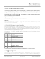
The document name for remote control is /rmt, hence (assuming the IO-FEP is listening to the IP address
10.0.0.1), requesting a document with the URL
http://10.0.0.1/rmt?tmp0=?
will let the IO-FEP reply the actual level in a one line text document:
tmp0=36.3
This way all parameters may be queried or set, you may use your favorite web browser to try out the
remote control of the IO-FEP manually.
4.3 The RS232 remote control interface
Beside the network interface, the IO-FEP also provides an RS232 serial port which can be used to control
the device remotely. Depending on the device address set, the IO-FEP either runs framed protocol with
start/stop characters and checksum or it provides a dumb terminal interface. The RS232 interface always
operates at 9600 baud, no parity, 8 data bits, one stop bit.
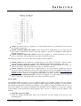
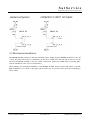
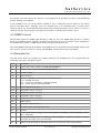
If an address 'A' .. 'G' is selected, the IO-FEP expects each message it receives to be packed into a frame as
described below.
char # example description
1
{
start character, always '{'
2
A
device address (A..G)
3
t
first character of the message body
.
m
message body ...
.
p
..
.
0
..
.
=
..
n-1
?
last character of the message body
n
}
end character, always '}'
n+1
.
checksum
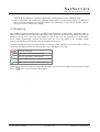
The checksum byte is calculated using an algorithm as implemented by the following formula:
This protocol type is known as MOD95- or Miteq protocol . The IO-FEP also packs it's reply in a protocol
frame as described above. incomplete frames, checksum errors or address mismatches let the IO-FEP ignore
(C) 2015, SatService GmbH
www.satnms.com
IO-FEP-UM-1505 Page 28/47
SatService
Gesellschaft für Kommunikationssysteme mbH
the message. The time between the characters of a message must be less than 5 seconds or the IO-FEP will
treat the message as incomplete.
If the IO-FEP is set to the device address 'NONE', it uses a simple line protocol instead of the framed
protocol described above. Messages sent to the IO-FEP have to be terminated with a carriage return
character (ASCII 13), the IO-FEP terminates replies with a CR/LF pair (ASCII 13/10). There is no echo for
characters entered, hence this protocol easily may be used for computer based remote control.
4.5 SNMP Control
The IO-FEP contains an SNMP agent listening at UDP port 161. The SNMP agent provides a common
subset pf the MIB-II system / interface parameters and gives full access to the remote control capabilities of
the IO-FEP with a number of MIB objects placed in the private.enterprises tree.
The actual MIB file defining the IO-FEP's private MIB may be downloaded from the IO-FEP istelf by FTP
(user 'service', password 'service'). The file 'IO.FEP.MIB' contains all neccessary information
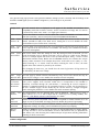
4.4 Parameter list
The table below shows the complete list of M&C parameters the IO-FEP knows. For each parameter the
valid range and a short description is given.
name
description
time
r/o Delivers date / time, format YYY-MM-DD HH:MM:SS
stim
Sets date / time, format YYY-MM-DD HH:MM:SS
sver
r/o Software version
srno
r/o Device serial no
caps
r/o Software capabilities, coded as bits in a decimal number:
2**0 = IO-FEP-E version
2**1 = protection / redundancy switching installed
2**2 = power supply monitoring installed
tmp0
r/o Board temperature (deg C)
tmp1
r/o Temperature sensor 1 (deg C)
tmp2
r/o Temperature sensor 2 (deg C)
tmp3
r/o Temperature sensor 3 (deg C)
tmp4
r/o Temperature sensor 4 (deg C)
outp
Digital outputs
wgsw
Waveguide switch actuation
prsw
Protection switch monitoring and control
stat
r/o I/O state
psua
r/o Power supply alarms (4 digits 0/1 for 24V, 24VEXT, 24V-RED and 24VEXT-RED) 0 states
OK, 1 states fault
tsya
r/o Time synchronisation alarm, 0 = NTP sync OK or disabled, 1 = NTP sync failed, 2 = NTP1
sync failed, but NTP2 sync was successful.
lsyn
r/o delivers a text describing the date/time and source of the recent clock synchronisation
(C) 2015, SatService GmbH
www.satnms.com
IO-FEP-UM-1505 Page 29/47
SatService
Gesellschaft für Kommunikationssysteme mbH
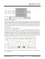
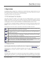
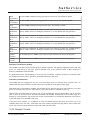
I/O state monitoring
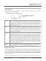
The command 'stat=?' returns a 32 character string which contains the complete I/O state of the IO-FEP,
coded in 5 hexadecimal numbers. Example:
000000000010 0400 00000006 00 00
|
|
| | |
|
|
| | no hi temperature faults
|
|
| no low temperature faults
|
|
S01=B, S02=A
|
Output 11 is ON
Input 5 is on
Inputs
The first number (12 characters, 48 bits) reports the state of the IO-FEP input circuits.
Each bit of the hexadecimal number corresponds to one input. The least significant bit
corresponds to input 1. A bit set to '1' reports an 'ON' or 'FLT' input, inputs which are 'OK'
or 'OFF' read '0'. The reported port states are logical states, they already include the
polarity inversion and filtering delay as defined in the setup for each individual port.
Unused ports always read '0'.
Outputs
The second number (4 characters, 16 bits) reports the actual state of the output ports in a
similar way. The contents of this is exactly the same as the reply to 'outp=?': pit 0
corresponds to the state of PhotoMOS output 1, bit 15 to the state of the relay 6. A bit set
to 1 tells that the output is 'ON' as displayed at the user interface. A software polling the
'stat=?' variable frequently may parse the output state from here rather from 'outp=?', thus
saving some protocol overhead.
WG Switch The third number (8 characters, 32 bits) reports the actual wave guide switch position.
Positions
Each switch encodes it's state in two bits of the number, WG switch 1 uses the least
significant bits. The bits reflect the state of the position indication circuits of each switch:
'01' tells that the switch is in position 'A', '10' signals position 'B'. The bit combinations '00'
and '11' both signal invalid states, a software monitoring the IO-FEP should decode this
and report it to the operator. The switch positions reported here are pre-processed by the
IO-FEP, not the raw position indication readings. If a switch is commanded to position 'X',
this position is reported immediately, even if the switch did not yet reach this position. After
the switch process has completed (or timed out) the real position is reported. This
behaviour nis necessary to hide the delayed / queued switching performed by the IO-FEP
from a M&C computer which expectes the IO-FEP to be a 'dumb PLC'. Unused
waveguide switches always report '00'
Temperature The words 4 (low temperature faults) and 5 (high temperature faults) encode the limit faults
Faults
for the temperature sensors of the IO-FEP. The least significant bit corresponds to the
internal board temperature sensor, bit 1 to the external temperature sensor 1 and so on.
Waveguide switch actuation
The command 'wgsw=xxxxxxxx' actuates one or more waveguide switches. Switch positions are coded the
same way as in the 'stat=?' reply described above: two bits for each switch, the least significant two bits for
switch 1. A bit combination '01' commands position 'A', '10' commands position 'B'. The combinations '00'
and '11' are ignored, the switch position remains unchanged. If multiple switch movements are commanded
at the same time, the switches move contemporaneously unless the number of parallel switch actuations has
been limited in the setup.
A computer controlling the IO-FEP may use the 'wgsw' command like it would control the actuation motors
(C) 2015, SatService GmbH
www.satnms.com
IO-FEP-UM-1505 Page 30/47
SatService
Gesellschaft für Kommunikationssysteme mbH
directly: switching on a motor and switching it off a few hundred milliseconds later. This is for compatibility
with software that expects a dumb switching unit to control the waveguide switches. In fact there are no
timing contstraints with the 'wgsw', the IO-FEP control the actuation timing off the switches internally.
Output control
The command 'outp=?' returns a 4 digit, 16 bit hexadecimal number showing the actual state of all outputs
of the IO-FEP. Bit 0 corresponds to the state of PhotoMOS output 1, bit 15 to the state of the relay 6. A bit
set to 1 tells that the output is 'ON' as displayed at the user interface.
Writing a 'outp=xxxx' sets all outputs of the IO-FEP. To set or clear a single output, you have to read the
actual state, set/clear the appropriate bit and send the number back to the IO-FEP.
Outputs which are not configured as type 'OUTPUT' always read '0'. Setting these outputs has no effect,
the IO-FEP silently ignores commands to outputs which are not configured to act as a general purpose
output.
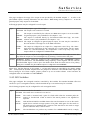
Protection switch control
The command 'prsw=?' returns a 32 digit hexadecimal string showing the state of up to 16 protection switch
units in the IO-FEP. The bit positions 0..7 (the rightmost two digits) refer to protection switch #1, bits 8..15
to protection switch #2 and so on. The status bit definitions for one protection switch are as follows:
0 (lsb)
1 = WG-Switch fault or instance not configured
1
0 = 1:1-SW-ONCE, 1 = 1:1-SW-ALWAYS
2
0 = DISABLED, 1 = ENABLED
3
0 = 1:1, 1 = 2:1 redundancy (bit 1 doesn't care in this case)
4
1 = fault in chain A
5
1 = fault in chain B
6
1 = SWITCHED
7 (msb) 0 = chain A selected, 1 = chain B selected
The same parameter is used to send commands to a protection switch unit in the IO-FEP. The format is
different to the status report described above. One command changes one parameter of a particular
protection switch:
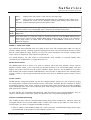
prsw=xy applies the command x (a one digit number 1..8) to the switch y (1..16). The command codes for x
are defined as follows:
1 Set the protection switch to UNUSED
2 Set the protection switch to 1:1-SW-ONCE
3 Set the protection switch to 1:1-SW-ALWAYS
4 Set the protection switch to DISABLED
5 Set the protection switch to ENABLED
6 Set the protection switch to position A
7 Set the protection switch to position B
8 Reset the SWITCHED flag of the protection switch
(C) 2015, SatService GmbH
www.satnms.com
IO-FEP-UM-1505 Page 31/47
SatService
Gesellschaft für Kommunikationssysteme mbH
9 Set the protection switch to SW-2TO1
Example: 'prsw=312' sets the protection 12 switch to SW-ALWAYS.
For 2:1 protection switches, you have to command the position of both switches involved in order to set the
redundant chain destination to CHAIN-A (B/A), CHAIN-B (A/B) or none (A/A).
(C) 2015, SatService GmbH
www.satnms.com
IO-FEP-UM-1505 Page 32/47
SatService
Gesellschaft für Kommunikationssysteme mbH
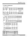
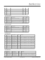
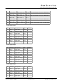
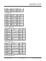
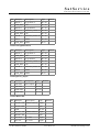
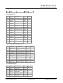
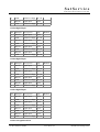
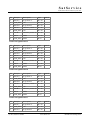
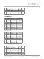
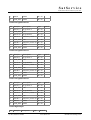
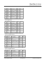
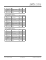
5 Connector Reference
Connector layout IO-FEP
Connector layout IO-FEP-E
CON1 LAN
Pin Identifier Description
Type
1
TX+
default Ethernet cabling (10Base-T) OUT
2
TX-
OUT
3
RX+
IN
(C) 2015, SatService GmbH
www.satnms.com
Remark
IO-FEP-UM-1505 Page 33/47
SatService
Gesellschaft für Kommunikationssysteme mbH
4
5
6
RX-
IN
7
8
CON2 power input
Pin Identifier
Description
Type
1
24V DC
voltage input for IO-FEP
DC in
2
GND DC
DC in
3
24V EXT
voltage input for WG Switches etc. DC in
4
GND EXT
Remark
DC in
CON3 power input
Pin Identifier
Description
Type
1
24V DC
voltage input for IO-FEP
DC in
2
GND DC
DC in
3
24V EXT
voltage input for WG Switches etc. DC in
4
GND EXT
Remark
DC in
CON4 HPA mute
Pin Identifier
Description
Type
1
MUT IN1
HPA 1 mute in
DC in
2
MUT OUT1 HPA 1 mute out DC out JP1: 1-2 SW mute / d-out, 2-3 HW mute
3
MUT IN2
4
MUT OUT2 HPA 2 mute out DC out JP2: 1-2 SW mute / d-out, 2-3 HW mute
5
MUT IN3
6
MUT OUT3 HPA 3 mute out DC out JP3: 1-2 SW mute / d-out, 2-3 HW mute
7
MUT IN4
8
MUT OUT4 HPA 4 mute out DC out JP4: 1-2 SW mute / d-out, 2-3 HW mute
9
MUT IN5
10
MUT OUT5 HPA 5 mute out DC out JP5: 1-2 SW mute / d-out, 2-3 HW mute
HPA 2 mute in
HPA 3 mute in
HPA 4 mute in
HPA 5 mute in
Remark
DC in
DC in
DC in
DC in
CON5 HPA mute
Pin Identifier
Description
Type
1
MUT IN6
HPA 6 mute in
DC in
2
MUT OUT6
HPA 6 mute out
DC out JP6: 1-2 SW mute / d-out, 2-3 HW mute
3
MUT IN7
HPA 7 mute in
DC in
(C) 2015, SatService GmbH
Remark
www.satnms.com
IO-FEP-UM-1505 Page 34/47
SatService
Gesellschaft für Kommunikationssysteme mbH
3
MUT IN7
HPA 7 mute in
DC in
4
MUT OUT7
HPA 7 mute out
DC out JP7: 1-2 SW mute / d-out, 2-3 HW mute
5
MUT IN8
HPA 8 mute in
DC in
6
MUT OUT8
HPA 8 mute out
DC out JP8: 1-2 SW mute / d-out, 2-3 HW mute
7
MUT IN9
HPA 9 mute in
DC in
8
MUT OUT9
HPA 9 mute out
DC out JP9: 1-2 SW mute / d-out, 2-3 HW mute
9
MUT IN10
HPA 10 mute in
DC in
10
MUT OUT10 HPA 10 mute out DC out JP10: 1-2 SW mute / d-out, 2-3 HW mute
CON6 digital input
Pin Identifier Description
Type
1
DIN 1
digital input
input
2
GND
refenece voltage DC out
3
DIN 2
digital input
4
GND
refenece voltage DC out
5
DIN 3
digital input
6
GND
refenece voltage DC out
7
DIN 4
digital input
8
GND
refenece voltage DC out
Remark
input
input
input
CON7 digital input
Pin Identifier Description
Type
1
DIN 5
digital input
input
2
GND
refenece voltage DC out
3
DIN 6
digital input
4
GND
refenece voltage DC out
5
DIN 7
digital input
6
GND
refenece voltage DC out
7
DIN 8
digital input
8
GND
refenece voltage DC out
Remark
input
input
input
CON8 digital input
Pin Identifier Description
Type
1
DIN 9
digital input
input
2
GND
refenece voltage DC out
3
DIN 10
digital input
4
GND
refenece voltage DC out
5
DIN 11
digital input
(C) 2015, SatService GmbH
Remark
input
input
www.satnms.com
IO-FEP-UM-1505 Page 35/47
SatService
Gesellschaft für Kommunikationssysteme mbH
6
GND
refenece voltage DC out
7
DIN 12
digital input
8
GND
refenece voltage DC out
input
CON9 digital input
Pin Identifier Description
Type
Remark
1
DIN 13
digital input
input
2
GND
refenece voltage DC out
3
DIN 14
digital input
4
GND
refenece voltage DC out
5
DIN 15
digital input
6
GND
refenece voltage DC out
7
DIN 16
digital input
8
GND
refenece voltage DC out
input
input
input
CON10 waveguideswitch 1
Pin Identifier
Description
Type
1
POS A 1
set position A
DC out
2
GND_EXT com
DC out
3
POS B 1
set position B
DC out
4
IND A 1
indication position A DC out
5
GND_EXT com
6
IND B 1
indication position B DC out
7
INH 1
inhibit
8
GND_EXT inhibit
Remark
DC out
DC out
DC in
CON11 waveguideswitch 2
Pin Identifier
Description
Type
1
POS A 2
set position A
DC out
2
GND_EXT com
DC out
3
POS B 2
set position B
DC out
4
IND A 2
indication position A DC out
5
GND_EXT com
6
IND B 2
indication position B DC out
7
INH 2
inhibit
8
GND_EXT inhibit
Remark
DC out
DC out
DC in
CON12 waveguideswitch 3
(C) 2015, SatService GmbH
www.satnms.com
IO-FEP-UM-1505 Page 36/47
SatService
Gesellschaft für Kommunikationssysteme mbH
Pin Identifier
Description
Type
Remark
1
POS A 3
set position A
DC out
2
GND_EXT com
DC out
3
POS B 3
set position B
DC out
4
IND A 3
indication position A DC out
5
GND_EXT com
6
IND B 3
indication position B DC out
7
INH 3
inhibit
8
GND_EXT inhibit
DC out
DC out
DC in
CON13 waveguideswitch 4
Pin Identifier
Description
Type
Remark
1
POS A 4
set position A
DC out
2
GND_EXT com
DC out
3
POS B 4
set position B
DC out
4
IND A 4
indication position A DC out
5
GND_EXT com
6
IND B 4
indication position B DC out
7
INH 4
inhibit
8
GND_EXT inhibit
DC out
DC out
DC in
CON14_Power_output
Pin Identifier
Description
Type
1
24V EXT
spare outputs DC out
2
24V EXT
DC out
3
GND EXT
DC out
4
GND EXT
DC out
Remark
CON15 RS232 I2C
Pin Identifier
Description
Type
Remark
1
RS232 0 TX RS232 access 0 output
2
RS232 0 RX
input
3
GND
DC out
4
RS232 1 TX RS232 access 1 output
5
RS232 1 RX
6
I2C SDA
I²C data
output
7
I2C SCL
I²C clock
output
input
(C) 2015, SatService GmbH
www.satnms.com
IO-FEP-UM-1505 Page 37/47
SatService
Gesellschaft für Kommunikationssysteme mbH
8
GND
DC out
CON16 digital out
Pin Identifier Description
Type
1
COM 1
input
2
COM 2
input
3
OUT 11
4
COM 2
5
OUT 12
6
COM 2
7
OUT 13
8
COM 2
input
9
COM 4
input
10
OUT 14
11
COM 5
12
OUT 15
13
COM 6
14
OUT 16
Remark
switched COM1 output
input
switched COM1 output
input
switched COM1 output
switched COM4 output
input
switched COM5 output
input
switched COM6 output
CON17 external temperature sensors
Pin Identifier
Description
Type
1
SENS OUT1 output to PT1000 DC out
2
SENS IN1
3
SENS OUT2 output to PT1000 DC out
4
SENS IN2
5
SENS OUT3 output to PT1000 DC out
6
SENS IN3
7
SENS OUT4 output to PT1000 DC out
8
SENS IN4
input to PT1000
input to PT1000
input to PT1000
input to PT1000
Remark
DC in
DC in
DC in
DC in
CON18 digital input
Pin Identifier Description
Type
1
DIN 17
digital input
input
2
GND
refenece voltage DC out
3
DIN 18
digital input
4
GND
refenece voltage DC out
5
DIN 19
digital input
(C) 2015, SatService GmbH
Remark
input
input
www.satnms.com
IO-FEP-UM-1505 Page 38/47
SatService
Gesellschaft für Kommunikationssysteme mbH
6
GND
refenece voltage DC out
7
DIN 20
digital input
8
GND
refenece voltage DC out
input
CON19 digital input
Pin Identifier Description
Type
1
DIN 21
digital input
input
2
GND
refenece voltage DC out
3
DIN 22
digital input
4
GND
refenece voltage DC out
5
DIN 23
digital input
6
GND
refenece voltage DC out
7
DIN 24
digital input
8
GND
refenece voltage DC out
Remark
input
input
input
CON20 digital input
Pin Identifier Description
Type
1
DIN 25
digital input
input
2
GND
refenece voltage DC out
3
DIN 26
digital input
4
GND
refenece voltage DC out
5
DIN 27
digital input
6
GND
refenece voltage DC out
7
DIN 28
digital input
8
GND
refenece voltage DC out
Remark
input
input
input
CON21 digital input
Pin Identifier Description
Type
1
DIN 29
digital input
input
2
GND
refenece voltage DC out
3
DIN 30
digital input
4
GND
refenece voltage DC out
5
DIN 31
digital input
6
GND
refenece voltage DC out
7
DIN 32
digital input
8
GND
refenece voltage DC out
Remark
input
input
input
CON22 waveguideswitch 6
(C) 2015, SatService GmbH
www.satnms.com
IO-FEP-UM-1505 Page 39/47
SatService
Gesellschaft für Kommunikationssysteme mbH
Pin Identifier
Description
Type
1
POS A 6
set position A
DC out
2
GND_EXT com
DC out
3
POS B 6
set position B
DC out
4
IND A 6
indication position A DC out
5
GND_EXT com
6
IND B 6
indication position B DC out
7
INH 6
inhibit
8
GND_EXT inhibit
Remark
DC out
DC out
DC in
CON23 waveguideswitch 5
Pin Identifier
Description
Type
1
POS A 5
set position A
DC out
2
GND_EXT com
DC out
3
POS B 5
set position B
DC out
4
IND A 5
indication position A DC out
5
GND_EXT com
6
IND B 5
indication position B DC out
7
INH 5
inhibit
8
GND_EXT inhibit
Remark
DC out
DC out
DC in
CON24 waveguideswitch 8
Pin Identifier
Description
Type
1
POS A 8
set position A
DC out
2
GND_EXT com
DC out
3
POS B 8
set position B
DC out
4
IND A 8
indication position A DC out
5
GND_EXT com
6
IND B 8
indication position B DC out
7
INH 8
inhibit
8
GND_EXT inhibit
Remark
DC out
DC out
DC in
CON25 waveguideswitch 7
Pin Identifier
Description
Type
1
POS A 7
set position A
DC out
2
GND_EXT com
DC out
3
POS B 7
DC out
set position B
(C) 2015, SatService GmbH
Remark
www.satnms.com
IO-FEP-UM-1505 Page 40/47
SatService
Gesellschaft für Kommunikationssysteme mbH
4
IND A 7
indication position A DC out
5
GND_EXT com
6
IND B 7
indication position B DC out
7
INH 7
inhibit
DC out
8
GND_EXT inhibit
DC out
DC out
the following connectors can only be found on the IO-FEP-E
CON26 digital input
Pin Identifier Description
Type
Remark
1
DIN 33
digital input
input
2
GND
refenece voltage DC out
3
DIN 34
digital input
4
GND
refenece voltage DC out
5
DIN 35
digital input
6
GND
refenece voltage DC out
7
DIN 36
digital input
8
GND
refenece voltage DC out
input
input
input
CON27 digital input
Pin Identifier Description
Type
Remark
1
DIN 37
digital input
input
2
GND
refenece voltage DC out
3
DIN 38
digital input
4
GND
refenece voltage DC out
5
DIN 39
digital input
6
GND
refenece voltage DC out
7
DIN 40
digital input
8
GND
refenece voltage DC out
input
input
input
CON28 waveguideswitch 9
Pin Identifier
Description
Type
1
POS A 9
set position A
DC out
2
GND_EXT com
DC out
3
POS B 9
set position B
DC out
4
IND A 9
indication position A DC out
5
GND_EXT com
6
IND B 9
Remark
DC out
indication position B DC out
(C) 2015, SatService GmbH
www.satnms.com
IO-FEP-UM-1505 Page 41/47
SatService
Gesellschaft für Kommunikationssysteme mbH
7
INH 9
inhibit
DC out
8
GND_EXT inhibit
DC out
CON29 waveguideswitch 10
Pin Identifier
Description
Type
1
POS A 10
set position A
DC out
2
GND_EXT com
DC out
3
POS B 10
set position B
DC out
4
IND A 10
indication position A DC out
5
GND_EXT com
6
IND B 10
indication position B DC out
7
INH 10
inhibit
DC out
8
GND_EXT inhibit
DC out
Remark
DC out
CON30 waveguideswitch 11
Pin Identifier
Description
Type
1
POS A 11
set position A
DC out
2
GND_EXT com
DC out
3
POS B 11
set position B
DC out
4
IND A 11
indication position A DC out
5
GND_EXT com
6
IND B 11
indication position B DC out
7
INH 11
inhibit
DC out
8
GND_EXT inhibit
DC out
Remark
DC out
CON31 waveguideswitch 12
Pin Identifier
Description
Type
1
POS A 12
set position A
DC out
2
GND_EXT com
DC out
3
POS B 12
set position B
DC out
4
IND A 12
indication position A DC out
5
GND_EXT com
6
IND B 12
indication position B DC out
7
INH 12
inhibit
DC out
8
GND_EXT inhibit
DC out
Remark
DC out
CON32 digital input
Pin Identifier Description
(C) 2015, SatService GmbH
Type
Remark
www.satnms.com
IO-FEP-UM-1505 Page 42/47
SatService
Gesellschaft für Kommunikationssysteme mbH
Pin Identifier Description
Type
Remark
1
DIN 41
digital input
input
2
GND
refenece voltage DC out
3
DIN 42
digital input
4
GND
refenece voltage DC out
5
DIN 43
digital input
6
GND
refenece voltage DC out
7
DIN 44
digital input
8
GND
refenece voltage DC out
input
input
input
CON33 digital input
Pin Identifier Description
Type
Remark
1
DIN 45
digital input
input
2
GND
refenece voltage DC out
3
DIN 46
digital input
4
GND
refenece voltage DC out
5
DIN 47
digital input
6
GND
refenece voltage DC out
7
DIN 48
digital input
8
GND
refenece voltage DC out
input
input
input
CON34 waveguideswitch 13
Pin Identifier
Description
Type
1
POS A 13
set position A
DC out
2
GND_EXT com
DC out
3
POS B 13
set position B
DC out
4
IND A 13
indication position A DC out
5
GND_EXT com
6
IND B 13
indication position B DC out
7
INH 13
inhibit
DC out
8
GND_EXT inhibit
DC out
Remark
DC out
CON35 waveguideswitch 14
Pin Identifier
Description
Type
1
POS A 14
set position A
DC out
2
GND_EXT com
DC out
3
POS B 14
set position B
DC out
4
IND A 14
indication position A DC out
(C) 2015, SatService GmbH
Remark
www.satnms.com
IO-FEP-UM-1505 Page 43/47
SatService
Gesellschaft für Kommunikationssysteme mbH
5
GND_EXT com
DC out
6
IND B 14
indication position B DC out
7
INH 14
inhibit
DC out
8
GND_EXT inhibit
DC out
CON36 waveguideswitch 15
Pin Identifier
Description
Type
1
POS A 15
set position A
DC out
2
GND_EXT com
DC out
3
POS B 15
set position B
DC out
4
IND A 15
indication position A DC out
5
GND_EXT com
6
IND B 15
indication position B DC out
7
INH 15
inhibit
DC out
8
GND_EXT inhibit
DC out
Remark
DC out
CON37 waveguideswitch 16
Pin Identifier
Description
Type
1
POS A 16
set position A
DC out
2
GND_EXT com
DC out
3
POS B 16
set position B
DC out
4
IND A 16
indication position A DC out
5
GND_EXT com
6
IND B 16
indication position B DC out
7
INH 16
inhibit
DC out
8
GND_EXT inhibit
DC out
(C) 2015, SatService GmbH
Remark
DC out
www.satnms.com
IO-FEP-UM-1505 Page 44/47
SatService
Gesellschaft für Kommunikationssysteme mbH
6 Specifications
Specifications IO-FEP
General Interfaces
qty
Connector remark
No.
System Interfaces
All interfaces (except the Ethernet-interface) have
to be connected via Mini Combicon MCV1,5/XXG-3,5
external
measurement
Temperature 4
17
via external PT1000 sensors, accuracy +/- 3°C,
range: -40 to +60°C
internal
measurement
Temperature 1
---
via internal on-chip-sensor, accurancy +/-3°C
real-time clock/ calendar. If power supply is
missing, a goldcap capacitor keeps the clock
running for min. 7 days
internal clock/ calendar
1
---
digital input
32
6, 7, 8, 9, via optocoupler, indication current: ~3mA @ 24V
18, 19, 20, DC
21
digital output
6
16
relay contacts, max. continuous current: 1A, max
continuous voltage: 24V DC
HPA-muting/ digital output
10
4, 5
Photomos-relays, per relay max. continuous
current: 130mA, max. continuous voltage: 48V, onstate-restistance ~25Ohm
HPA-muting matrix
10x8
waveguide-switching
8
waveguide-indication
8
via optocoupler, indication current: ~3mA @ 24V
DC
inhibit-indication
8
indication current ~5mA @ 24V DC
power output
1
14
24V DC, max 500mA
I²C
1
15
for special requirements,
customized Software
RS232
1
15
for controlling the IO-FEP
Ethernet
1
1
RJ45, 10/100-Base-T, for controlling the IO-FEP
via HTTP GET or any Web-browser
software HPA-muting
hardware-HPA-muting
or
DIP-switches
for
10, 11, 12, maximum peak switching current: 5A
13, 22, 23,
24, 25
only
usable
with
M&C Interface Specification
interface for M&C and user
(C) 2015, SatService GmbH
10/ 100-Base-T, Via HTTP GET requests, RS232,
SNMP
www.satnms.com
IO-FEP-UM-1505 Page 45/47
SatService
Gesellschaft für Kommunikationssysteme mbH
Electrical and Mechanical
Specification, Environmental
conditions
Supply Voltage
24 V unregulated D/C
Power consumption 24V DC
2, 3
max. 150mA
Power consumption 24V EXT
2, 3
max. 450mA (excluding power output at CON14
and the switching current of the waveguide
switches)
Temperature range
5° to 50° C
Humidity
up to 90% non condensing
DIN rail module
264 x 165 x 60 mm
Weight
1,5 kg
Specifications IO-FEP-E
General Interfaces
qty
Connector No.
System Interfaces
remark
All interfaces (except the Ethernet-interface)
have to be connected via Mini Combicon
MCV1,5/XX-G-3,5
external
Temperature 4
measurement
17
via external PT1000 sensors, accuracy +/3°C, range: -40 to +60°C
internal
Temperature 1
measurement
---
via internal on-chip-sensor, accurancy +/3°C
internal clock/ calendar
1
---
real-time clock/ calendar. If power supply is
missing, a goldcap capacitor keeps the clock
running for min. 7 days
digital input
48
6, 7, 8, 9, 18, 19, 20, via optocoupler, indication current: ~3mA @
21, 26, 27, 32, 33
24V DC
digital output
6
16
relay contacts, max. continuous current: 1A,
max continuous voltage: 24V DC
HPA-muting/ digital output
10
4, 5
Photomos-relays, per relay max. continuous
current: 130mA, max. continuous voltage:
48V, on-state-restistance ~25Ohm
HPA-muting matrix
10x16
waveguide-switching
16
waveguide-indication
16
via optocoupler, indication current: ~3mA @
24V DC
inhibit-indication
16
indication current ~5mA @ 24V DC
power output
1
14
24V DC, max 500mA
I²C
1
15
for special requirements, only usable with
(C) 2015, SatService GmbH
software HPA-muting or DIP-switches for
hardware-HPA-muting
10, 11, 12, 13, 22, maximum peak switching current: 5A
23, 24, 25, 28, 29,
30, 31, 34, 35, 36,
37
www.satnms.com
IO-FEP-UM-1505 Page 46/47
SatService
Gesellschaft für Kommunikationssysteme mbH
customized Software
RS232
1
15
for controlling the IO-FEP
Ethernet
1
1
RJ45, 10/100-Base-T, for controlling the
IO-FEP via HTTP GET or any Webbrowser
M&C
Specification
Interface
interface for M&C and
user
10/ 100-Base-T, Via HTTP GET requests,
RS232, SNMP
Electrical
and
Mechanical Specification,
Environmental
conditions
Supply Voltage
24 V unregulated D/C
Power consumption 24V
DC
2, 3
max. 200mA
Power consumption 24V
EXT
2, 3
max. 650mA (excluding power output at
CON14 and the switching current of the
waveguide switches)
Temperature range
5° to 50° C
Humidity
up to 90% non condensing
DIN rail module
434 x 165 x 60 mm
Weight
2,2 kg
(C) 2015, SatService GmbH
www.satnms.com
IO-FEP-UM-1505 Page 47/47