1
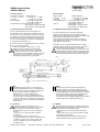
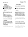
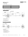
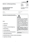
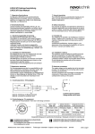
TIM Montageanleitung
TIM User Manual
1 Allgemeine Beschreibung
2
1 General description
2
2 Sicherheitshinweise
2
2
2
2
2
2
2
Bestimmungsgemäße Verwendung
Installation & Inbetriebnahme
Anschlüsse prüfen
Einschalten des Systems
Messwerte prüfen
Funktionsfähigkeit prüfen
Funktionsstörung
2
2
2
2
2
2
2
2
2 Safety instructions
2.1
2.2
2.3
2.4
2.5
2.6
2.7
2.1
2.2
2.3
2.4
2.5
2.6
2.7
Intended conditions of use
Installation & startup
Check connections
Turning on the system
Check measured values
Check functionality
Failure malfunction
3
3.1
3.2
3.3
Elektrische Daten
Massekonzept und Schirmung
EMV
Schweissen
3
3
3
3
3
3.1
3.2
3.3
Electrical data
Machine ground and cable shielding
EMC
Welding
3
3
3
3
4
4.1
4.1
4.2
4.3
4.4
Montagehinweise
Bohrung in der Kolbenstange
Positionsgeber
Steckflansch Ø 48
Schraubflansch M18
Allgemeine Information
4
4
4
4
4
4
4
4.1
4.2
4.3
4.4
4.5
Instructions for installation
Bore diameter of piston rod
Position marker
Plug-in flange Ø 48
Screw flange M18
General information
4
4
4
4
4
4
5
Einbau & Installation
5.1 Steckflansch
5.2 Schraubflansch
5.3 Positionsgeber
5
5
7
9
5
Mounting & installation
5.1 Plug-in flange
5.2 Screw flange
5.3 Position marker
5
5
7
9
6 Elektrischer Anschluss
9
9
9
6 Electrical connection
6.1 Anschlussbelegung analoge Typen
6.2 Anschlussbelegung CANopen
6.1 Connection assignment analog versions
6.2 Connection assignment CANopen
9
9
9
7 Notwendiges Zubehör
9
7 Required accessories
9
8 Bestellcode
9
8 Ordering code
9
9 CANopen-Schnittstelle
9
9 CANopen Interface
9
Achtung!
Bitte unbedingt beachten!
Aufgrund von Produktanpassungen wurde die Anschlussbelegung (siehe Punkt 6) geändert.
Caution!
Please pay attention!
Due to product changes the pin assignment (see point 6) was changed.
Artikelnummer: 517991/07
Änderungen vorbehalten / Subject to change without notice
2014/11
Seite / page 1
TIM Montageanleitung
TIM User Manual
1 Allgemeine Beschreibung
1 General description
Die Baureihe TIM ist ein magnetostriktiver Wegaufnehmer
für direkte, genaue und absolute Messung von Wegen bzw.
Längen in der Steuerungs-, Regelungs- und Messtechnik.
The TIM series is a magnetostricitve transducer for direct,
accurate measurement of travel in display- or feedback
applications.
2 Sicherheitshinweise
2 Safety instructions
Unsere Produkte sind regelmäßig nicht für Luft- und
Raumfahrtanwendungen zugelassen und dürfen nicht
in kerntechnischen oder militärischen, insbesondere
ABC-relevanten Applikationen verwendet werden.
Weitere Informationen s. unsere AGBs.
Our products are regularly not approved for aeronautic or
aerospace applications and are not allowed to be used in
nuclear or military, in particular ABC-relevant applications.
For more information see our Terms and Conditions.
2.1 Bestimmungsgemäße Verwendung
Der Wegaufnehmer wird zu seiner Verwendung in eine
Maschine oder Anlage eingebaut. Er bildet zusammen mit
einer Steuerung (z.B. SPS) ein Wegmesssystem und darf
auch nur für diese Aufgabe eingesetzt werden.
2.1 Intended conditions of use
The transducer is intended to be installed in a machine or
system. Together with a controller (e.g. PLC) it comprises
a position measuring system and may only be used for
this purpose.
Unbefugte Eingriffe, nicht bestimmungsgemäße
Verwendung oder Nichtbeachtung der Montagehinweise
führen zum Verlust von Gewährleistungs-, Garantie- und
Haftungsansprüchen.
Unauthorized modifications, improper usage or nonobservance of the instructions for installation will result in the
loss of warranty and liability claims.
2.2 Installation & Inbetriebnahme
Der Wegaufnehmer ist nur von Fachpersonal und unter
Berücksichtigung aller geltenden Sicherheitsvorschriften in
Betrieb zu nehmen.
Alle Maßnahmen zum Schutz von Personen und Sachen
bei einem Defekt des Wegaufnehmers müssen vor der
Inbetriebnahme getroffen werden.
Starke magnetische oder elektromagnetische
Felder in unmittelbarer Nähe zum Wegaufnehmer
können zu fehlerhaften Signalen führen!
2.2 Installation & startup
The transducer must be installed by qualified personnel in
consideration of all relevant safety regulations.
2.3 Anschlüsse prüfen
Falsche Verbindungen und Überspannung können zur
Beschädigung des Wegaufnehmers führen. Prüfen Sie
deshalb vor dem Einschalten die Anschlüsse immer
sorgfältig.
Potentialdifferenzen zwischen Versorgung GND
und Signal GND sind zu vermeiden.
Durch Potentialdifferenzen zwischen Versorgung
GND und Signal GND kann der Wegaufnehmer
zerstört werden!
2.3 Check connections
Improper connections and overvoltage can damage the
transducer. Please always check the connections carefully
before turning on the system.
2.4 Einschalten des Systems
Das System kann beim Einschalten unkontrollierte
Bewegungen ausführen, vor allem wenn der
Wegaufnehmer Teil eines Regelsystems ist,
dessen Parameter noch nicht eingestellt sind.
Stellen Sie daher sicher, dass hiervon keine
Gefahren für Personen und Sachen ausgehen
können.
2.4 Switching-on the system
The system may execute uncontrolled movements
during first turning-on mainly when the transducer is
a part of a control system whose parameters have
not yet been set. Therefore make sure that hereof
no dangers for personal and property can result.
2.5 Messwerte prüfen
Nach dem Austausch eines Wegaufnehmers wird
empfohlen, die Ausgangswerte in der Anfangs- und
Endstellung des Positionsgebers im Handbetrieb zu
überprüfen. (Änderungen oder fertigungsbedingte
Streuungen vorbehalten)
2.5 Check measured values
After replacing or repairing a transducer, it is advisable to
verify the output values for the start and end position of the
position marker in manual mode. (Transducers are subject to
modification or manufacturing tolerances)
2.6 Funktionsfähigkeit prüfen
Die Funktionsfähigkeit des Wegaufnehmers und aller damit
verbundenen Komponenten ist regelmäßig zu überprüfen
und zu protokollieren.
2.6 Check functionality
The functionality of the transducer and all its associated
components should be regularly checked and recorded.
2.7 Funktionsstörung
Wenn der Wegaufnehmer nicht ordnungsgemäß arbeitet,
ist er außer Betrieb zu nehmen und gegen unbefugte
Benutzung zu sichern.
2.7 Failure malfunction
If the transducer doesn‘t operate properly, it should be taken
out of service and protected against unauthorized use.
Artikelnummer: 517991/07
All necessary safety measures to protect personnel and
property in case of a transducer defect or failure must be
taken before startup.
Strong magnetic or electromagnetic fields in close
vicinity to the transducer may lead to faulty readings!
Potential differences between supply voltage GND
and signal GND must be avoided.
With different potentials between supply voltage GND
and signal GND the transducer can be destroyed!
Änderungen vorbehalten / Subject to change without notice
2014/11
Seite / page 2
TIM Montageanleitung
TIM User Manual
3 Elektrische Daten
3 Electrical data
Versorgungsspannung:
Mobilelektronik
el. Code 6 _ _ und 8 _ _: 12 / 24 VDC ( 8 ...32 VDC)
el. Code 9 _ _:
24 VDC (16…32 VDC)
Stromaufnahme:
< 100 mA typisch @12 VDC
< 50 mA typisch @24 VDC
Lastwiderstand RL : Spannungsausgang > 10 kΩ
Stromausgang < 250 Ω @12 VDC
Stromausgang < 500 Ω @24 VDC
Supply voltage:
Mobile electronics
el. Code 6 _ _ and 8 _ _:
12 / 24 VDC ( 8...32 VDC)
el. Code 9 _ _ :
24 VDC (16...32 VDC)
Current consumption: < 100 mA typical @12 VDC
< 50 mA typical @24 VDC
Load RL:
voltage output > 10 kΩ
current output < 250 Ω @12 VDC
current output < 500 Ω@24 VDC
3.1 Massekonzept und Schirmung
3.1 Machine ground and cable shielding
Für den fehlerfreien Betrieb und zum Ausgleich von
Potentialdifferenzen ist der Zylinder auf Maschinenmasse
zu legen; dies ist meist durch den mechanischen Kontakt
des Zylinders mit anderen Maschinenelementen gegeben.
Falls der Zylinder isoliert mit der Maschine verbunden ist,
muss eine separate Erdung z.B. durch ein Erdungsband
an den Zylinder gewährleistet sein.
Durch den metallischen Hydraulikzylinder ist der verbaute
Sensor ausreichend geschirmt.
Es ist daher werkseitig über den Stecker- oder den
Kabelabgang keine gesonderte Schirmung geführt.
Bei starken HF-Einstrahlungen ist es notwendig,
geschirmte Leitungen zu verwenden. Dann muss
jedoch anwenderseitig abhängig vom Massekonzept
geprüft werden, ob der Schirm nur einseitig oder
beidseitig auf Maschinenmasse gelegt wird.
For correct operation and to compensate potential
differences, the cylinder must be connected to machine
ground. This is usually given by the mechanical contact of the
cylinder with the other parts of the machine.
If the cylinder is connected to the machine separately, a
separate grounding must be ensured eg by an grounding
strap directly to the cylinder.
The built-in sensor is shielded sufficiently by the metallic
hydraulic cylinder. Therefore, the factory does not provide a
separate shielding via the connector or cable outlet.
In case of strong HF interference, it is necessary to use
shielded cables. It requires checking, depending on the
user´s grounding concept, if only one side or both sides
of the shield should be connected to machine ground.
3.2 EMV
Die EMV Messungen wurden in einem ReferenzZylinder durchgeführt. Die gemessenen EMV-Werte
können bei unterschiedlichen Zylinderausführungen
jedoch deutlich abweichen! Bei kritischen
Applikationen ist es daher notwendig, das
Gesamtsystem einer eigenen EMV Erprobung zu
unterziehen! Der rückseitige Flanschdeckel mit dem
elektrischen Anschluss ist im Zylinder vollständig zu
integrieren oder durch ein entsprechendes Gehäuse
abzuschirmen!
3.2 EMC
The EMC measurements were accomplished in a
reference cylinder. The measured EMC values can
however deviate clearly when using different cylinders!
In critical applications it is therefore necessary to submit
the existing complete system to its own EMC testing!
The rear cover of the flange with the electrical
connection must be completely integrated into cylinder or
must be shielded by an appropriate housing!
3.3 Schweissen
Bei Schweissarbeiten am Zylinder oder an
angrenzenden Bauteilen ist folgendes zu beachten,
damit es durch den Schweissstrom zu keinen
Beschädigungen am Sensor oder an Dichtungen
kommt:
- der Sensor ist vor Schweissbeginn möglichst
auszubauen
- bei eingebautem Sensor sind alle Sensoranschlüsse während des Schweissens abzuklemmen
- der Masseanschluss des Schweissgerätes darf
niemals am Zylinder oder an der Kolbenstange
befestigt werden
3.3 Welding
When welding on the cylinder or adjacent components,
the following must be observed to avoid any damage to
the sensor or seals by welding current:
- preferably, the sensor should be removed before
welding
- with a built-in sensor, all sensor connections must be
disconnected during welding
- the grounding connection of the welding unit must
never be attached to the cylinder or the piston rod
Artikelnummer: 517991/07
Änderungen vorbehalten / Subject to change without notice
2014/11
Seite / page 3
TIM Montageanleitung
TIM User Manual
4
4
Montagehinweise
4.1 Bohrung der Kolbenstange
Die Bohrung in der Kolbenstange ist abhängig vom Druck
und der Verfahrgeschwindigkeit auszulegen.
Empfohlener Bohrungsdurchmesser Dk ≥ 12,7 mm.
Das Ende des TIM-Stabes ist vor Verschleiß zu schützen.
Der Positionsgeber darf nicht auf dem Stab schleifen.
Wird der Schraubflansch in einen Zylinder aus
magnetisierbaren Material eingebaut, dann ist
unbedingt darauf zu achten, dass der Abstand
zwischen Positionsgeber in der Nullpunktstellung
und dem Zylinder min. 15 mm axial beträgt!
Instructions for installation
4.1 Bore diameter of piston rod
The bore in the piston rod has to be laid out dependent on
the pressure and the operating speed.
The recommended bore diameter amounts to Dk ≥ 12,7 mm.
The end of the TIM rod has to be protected against wear.
The position marker may not touch the rod.
When the screw flange will be mounted in a cylinder
of magnetizable material, it‘s important that the axial
distance between the position marker at the zero point
and the cylinder is min. 15 mm.
4.2 Positionsgeber
Für die direkte Hubmessung im Zylinder wird der
Positionsgeber direkt auf dem Kolbenboden montiert:
- Z-TH1-P18 und -P19: mit 2 Schrauben M3 oder M4 (je
nach Positionsgeber), Anzugsmoment für M4 Schrauben
max. 1 N. Alternativ kann der Positionsgeber auch durch
einen Schraubring oder eine Einpressverbindung fixiert
werden.
- Z-TIM-P20: mit nichtmagnetischer Federscheibe und
Sicherungsring.
Die Aufnahme des Positionsgebers sollte über
nichtmagnetisches Material (z.B. Edelstahl, Messing,
Aluminium, Kunststoff) erfolgen. Gegebenenfalls ist eine
nichtmagnetische Distanzscheibe (min. 5 mm stark)
zwischen Positionsgeber und Kolbenboden zu montieren.
4.2 Position marker
For direct stroke measuring in a cylinder the position marker
has to be fixed directly on the cylinder‘s piston bottom:
- Z-TH1-P18 and -P19: fixed with 2 screws M3 or M4
(depending on the position marker), Fastening torque for M4
screws max. 1 Nm. Alternatively the position marker can also
be fixed by a threaded ring or by a press-fit-connection.
- Z-TIM-P20: with non magnetic spring washer and circlip.
4.3 Steckflansch Ø 48
Der Sensor mit Flanschgehäuse Ø 48 mm wird in eine
Passbohrung Ø 48 H8 eingebaut.
Die Abdichtung des Flansches zum Zylinder erfolgt über
den mitgelieferten O-Ring und den Stützring.
Der Flansch des Sensors wird durch Gewindestifte M5
fixiert.
4.3 Plug-in flange Ø 48
The sensor with Ø 48 mm flange has to be mounted in a
fitting bore Ø 48 H8.
The sealing between the flange and the cylinder is realized
with an O-ring and a support ring, which are included in
delivery.
The flange of the sensor will be fixed with M5 set screws.
4.4 Schraubflansch M18
Der Sensor wird mit Hilfe des Sechskantflansches (SW46)
eingeschraubt. Hierbei darf das Anzugsmoment 50 Nm
nicht überschreiten!
Der mitgelieferte O-Ring dichtet den Druckbereich des
Zylinders am Einschraubloch ab. Die Flanschauflagefläche
muss vollständig an der entsprechenden Auflagefläche des
Zylinders aufliegen.
4.5 Allgemeine Informationen
Bei waagrechter Montage von Wegaufnehmern mit einem
elektrischen Messbereich über 1000 mm empfiehlt es sich,
den Stab am Ende abzustützen.
Der Bereich für Kabel- und Litzenabgang muss
ausreichend dimensioniert werden, der Mindestbiegeradius
ist einzuhalten und scharfe Kanten sind zu vermeiden!
Artikelnummer: 517991/07
For the mounting of the position marker non-magnetic
material (e.g. stainless steel, brass, aluminum, plastic) should
preferably be used. You have to mount a non-magnetizable
spacer of min. 5 mm thickness between position marker and
cylinder‘s piston bottom if necessary.
4.4 Screw flange M18
The sensor has to be screwed in via the hexagon flange
(SW46). Here the fastening torque may not exceed 50 Nm!
The provided O-ring seals the pressure area of the cylinder at
the screw plug hole. The contact surface of the flange must
rest completely against the mounting surface of the cylinder.
4.5 General information
For horizontal mounting of the transducer with an electrical
range longer than 1000 mm it is advisable to support or
attach the rod at the end.
For the area of the cable and lead wire please take care that
enough space is available, the minimum bending radius must
be observed and sharp edges must be avoided.
Änderungen vorbehalten / Subject to change without notice
2014/11
Seite / page 4
TIM Montageanleitung
TIM User Manual
5
Einbau / Installation
Mechanische Ausführungen / Mechanical configuration
Mechanische Ausführung / Mechanical configuration
Flansch /Flange
Code 305
Steckflansch / Plug-in flange Ø 48 mm
Code 306
Schraubflansch / Screw flange M18x1,5
5.1 Steckflansch / Plug-in flange (Code 305)
Kabelabgang / Cable connection
* min. Biegeradius NT-Standardkabel:
bei beweglicher Verlegung = 24 mm
bei fester Verlegung = 5 mm
min. bending radius NT standard cable:
in case of movable assembly = 24 mm
in case of fixed assembly = 5 mm
Steckersystem M12x 1 / Plug system M12x 1
*** min. Biegeradius NT-Standardlitzen:
bei beweglicher Verlegung = 10mm
bei fester Verlegung = 3mm
min. bending radius NT standard lead wires:
in case of movable assembly = 10mm
in case of fixed assembly = 3mm
Artikelnummer: 517991/07
Änderungen vorbehalten / Subject to change without notice
2014/11
Seite / page 5
TIM Montageanleitung
TIM User Manual
Einbaubeispiel Kabelabgang / Installation example cable connection
Einbaubeispiel Steckersystem M12x 1 / Installation example plug system M12x 1
∅ Dk siehe / see 4.1
Einzelheit X, nichtmagnetisierbarer Werkstoff
Detail X, non-magnetizable material
Artikelnummer: 517991/07
Einzelheit X, magnetisierbarer Werkstoff
Detail X, magnetizable material
Änderungen vorbehalten / Subject to change without notice
Einzelheit Y
Detail Y
2014/11
Seite / page 6
TIM Montageanleitung
TIM User Manual
5.2 Schraubflansch / Screw flange (Code 306)
Kabelabgang / Cable connection
* min. Biegeradius NT-Standardkabel:
bei beweglicher Verlegung = 24 mm
bei fester Verlegung = 5 mm
min. bending radius NT standard cable:
in case of movable assembly = 24 mm
in case of fixed assembly = 5 mm
Stecker M12x 1 / Plug M12x 1
Artikelnummer: 517991/07
Änderungen vorbehalten / Subject to change without notice
2014/11
Seite / page 7
TIM Montageanleitung
TIM User Manual
Einbaubeispiel / Installation example
∅ Dk siehe / see 4.1
Einzelheit X, nichtmagnetisierbarer Werkstoff
Detail X, non-magnetizable material
Einzelheit X, magnetisierbarer Werkstoff
Detail X, magnetizable material
∅ 15,4x2,1
Einzelheit Y
Detail Y
Artikelnummer: 517991/07
Änderungen vorbehalten / Subject to change without notice
2014/11
Seite / page 8
TIM Montageanleitung
TIM User Manual
5.3 Positionsgeber / Position marker
6 Elektrischer Anschluss / Electrical connection
6.1 Anschlussbelegung analoge Typen / Connection assignment analog versions
Stecker / Plug
104 / 4_ _
Kabel / Cable
251 / 253 / 255 / 260
Signal
el. Code 821*
Signal
el. Code 841* / 851*
Signal
el. Code 911*
PIN 1
BN braun / brown
+ 12 / 24 VDC
+ 12 / 24 VDC
+ 24 VDC
PIN 2
GN grün / green
4…20 mA
0,5…4,5 VDC
0,25…4,75 VDC
0…10 VDC
PIN 3
WH weiss / white
GND
GND
GND
PIN 4
nicht anschliessen / nicht anschliessen / nicht anschliessen / nicht anschliessen /
do not connect
do not connect
do not connect
do not connect
* Steigende Kennlinie ab Flansch / Rising characteristic from flange
Polbild 4-polig
M12x1 Flanschstecker bzw. Steckersystem
A-codiert
Pin Arrangement 4-pin
M12x1 plug or plug system
A-coded
Konfektionierte Kabel können abweichende Farbbelegung aufweisen !
Customized cable may show different color coding !
6.2 Anschlussbelegung CANopen-Schnittstelle/ Connection assignment CANopen interface
Stecker / Plug
106 / 4 _ _
Signal
el. Code 61_*
PIN 1
Nicht angeschlossen /
not connected
PIN 2
+ 12 / 24 VDC
PIN 3
GND
PIN 4
CAN high
PIN 5
CAN low
Polbild 5-polig
M12x1 Flanschstecker bzw. Steckersystem
A-codiert
Pin Arrangement 5-pin
M12x1 plug or plug system
A-coded
7 Notwendiges Zubehör
7 Required accessories
•
•
•
•
•
•
•
Positionsgeber Z-TH1-P18 (Art.Nr. 005697)
Positionsgeber Z-TH1-P19 (Art.Nr. 005698)
Positionsgeber Z-TIM-P20 (Art.Nr. 005699)
Position marker Z-TH1-P18 (P/N 005697)
Position marker Z-TH1-P19 (P/N 005698)
Position marker Z-TIM-P20 (P/N 005699)
8 Bestellcode / Ordering code
TIM-_ _ _ _-_ _ _-_ _ _- _ _ _
Elektrischer Anschluss/
Electrical connection
Elektrischer Messbereich /
Electrical measuring range
Mechanische Ausführung /
Mechanical configuration
9 CAN Schnittstelle
Die Beschreibung der CANopen Schnittstelle sowie das
elektronische Datenblatt (EDS) sind zum Download auf der
Novotechnik Homepage unter Downloads/Gebrauchsanleitungen
verfügbar.
Artikelnummer: 517991/07
Elektrische Schnittstelle /
Electrical interface
9 CAN Interface
The description of CANopen interface and the electronic
data sheet (EDS) can be downloaded from Novotechnik
web site, see Downloads/Operating manuals.
Änderungen vorbehalten / Subject to change without notice
2014/11
Seite / page 9