
1
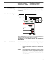
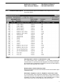
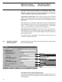
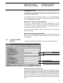
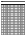
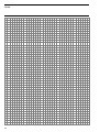
User manual
Intelligent Installation System
Universal Dimmer
UD/S 2.300.1
Contents
Seite
1
1.1
1.2
1.3
1.4
1.5
Device configuration . . . . . . . . . . . . . . . . . . . . . . . . . . . . . . . . . .
Introduction . . . . . . . . . . . . . . . . . . . . . . . . . . . . . . . . . . . . . . . . . . .
Load types . . . . . . . . . . . . . . . . . . . . . . . . . . . . . . . . . . . . . . . . . . .
Output power . . . . . . . . . . . . . . . . . . . . . . . . . . . . . . . . . . . . . . . . .
Performance characteristics . . . . . . . . . . . . . . . . . . . . . . . . . . . . . .
Behaviour on initialisation and in event of an error . . . . . . . . . . . .
2
2
2
2
3
4
2
2.1
2.2
Installation and commissioning . . . . . . . . . . . . . . . . . . . . . . . . .
Connection diagram . . . . . . . . . . . . . . . . . . . . . . . . . . . . . . . . . . . .
Load detection . . . . . . . . . . . . . . . . . . . . . . . . . . . . . . . . . . . . . . . .
5
5
5
3
3.1
3.2
3.3
3.4
3.5
3.6
ETS project design . . . . . . . . . . . . . . . . . . . . . . . . . . . . . . . . . . . .
Communication objects . . . . . . . . . . . . . . . . . . . . . . . . . . . . . . . . .
Parameter window: General . . . . . . . . . . . . . . . . . . . . . . . . . . . . . .
Parameter window: Dimming general . . . . . . . . . . . . . . . . . . . . . .
Parameter window: Dimming . . . . . . . . . . . . . . . . . . . . . . . . . . . . .
Parameter window: Preset . . . . . . . . . . . . . . . . . . . . . . . . . . . . . . .
Parameter window: Staircase lighting . . . . . . . . . . . . . . . . . . . . . .
6
7
9
10
11
12
13
4
4.1
4.2
4.3
Appendix . . . . . . . . . . . . . . . . . . . . . . . . . . . . . . . . . . . . . . . . . . . .
Technical data . . . . . . . . . . . . . . . . . . . . . . . . . . . . . . . . . . . . . . . . .
Status report function . . . . . . . . . . . . . . . . . . . . . . . . . . . . . . . . . . .
Table of error codes . . . . . . . . . . . . . . . . . . . . . . . . . . . . . . . . . . . .
15
15
16
17
This manual describes the function of the EIB universal dimmer UD/S 2.300.1
with the application program „Dim Stairc.fct Slave/1“.
Subject to change without prior notice.
1
Application software
Type: Universal Dimmer
1
Device configuration
1.1
Introduction
– Dim Stairc.fct Slave/1
– GH Q631 0045 R0111
The universal dimmer UD/S 2.300.1 can be universally implemented in
lighting technology and combines many functions and possibilities in a small
space.
The device can dim two independent groups of luminaries via the ABB i-bus®
EIB, each with a maximum output power of 300 W. Various types of luminaries
can be connected to both outputs.
The comprehensive functionality of the device enables intelligent and userfriendly lighting control. It is suitable for use both in the residential sector and
in commercial applications.
1.2
Load types
The dimmer is designed for operations with various types of luminaries (load
types).
Apart from resistive loads, there are also inductive or capacitive loads. The
following table indicates which load type generally applies to transformers or
luminaries:
Transformer or luminary
Incandescent
230V halogen lamps
Conventional low voltage transformer
Electronic low voltage transformer
Load type
resistive
resistive
inductive
capacitive
Inductive loads are dimmed via phase control while capacitive loads are
dimmed via phase invertal control. The automatic load detection of the
dimmer specifies the connected load type and adapts the operating mode
accordingly. Resistive loads can generally be dimmed using both operating
modes.
Note:
Both outputs A and B can operate different load types. It is however
not permitted to mix inductive and capacitive loads at the same
output.
The use of ABB transformers is recommended.
1.3
Output power
A maximum capacity of 300 W (VA) (apparent power) can be operated per
output. If only one output is connected, the maximum power at this output is
500 W (VA). The minimum power per output is 40 W (VA).
The maximum output power of the device is made available over the total
operating temperature range of – 5°C to + 45°C.
2
Application software
Type: Universal Dimmer
1.4
Performance
characteristics
– Dim Stairc.fct Slave/1
– GH Q631 0045 R0111
The following section outlines particular functions of the dimmer. There is a
more detailed description in the section „ETS project design“.
Automatic load detection: Automatic load detection checks the loads that
are connected to both outputs and sets the operating mode accordingly
(phase control or phase invertal control). Both outputs are triggered briefly
which generally leads to the lamps lighting up temporarily.
Soft start: The dimmer has an integrated „Soft start“ function available
(„switch on softly“). In order to protect the lamps, no sudden brightness
changes are carried out when they are switched on. This is also more
pleasant for any observers. It can also be set whether the lamps should
immediately jump or dim to new brightness values.
Presets: Presets are predetermined brightness values that are activated
on receipt of a 1 bit telegram. They are assigned parameters in ETS.
It is therefore possible to implement lightscenes with minimum time and effort.
Dimming thresholds and lamp life: The operation of specific lamp types
with a capacity slightly below the nominal value can extend the service life
of the lamps. If the lamps are dimmed down to a very low setting, the service
life of the lamps is visibly shortened. Infinitely variable lower and upper
dimming thresholds have therefore been introduced whereby it is not possible
to exceed or fall below the brightness value.
Staircase lighting function: The staircase lighting function serves to automatically dim the lighting until it switches off after a set period. It consists of
two intervals: the operating time and dimming down period.
Slave function: The slave function is used to combine the dimmer with a
central lighting control system. The master control unit (e.g. the light controller
LR/S 2.2.1) sends brightness values which are triggered by the assigned
dimming output. If required, the slave function can be deactivated during
operation e.g. to enable the lighting to be operated directly.
Safety after mains failure: On bus voltage failure, the dimmer switches off
all the outputs. The current brightness value is stored. The behaviour of
the dimmer on bus voltage recovery can be set. If required, the previous
brightness value can be restored. If the bus voltage is backed up and the 230
V mains supply fails, the previous brightness value is immediately set on
voltage recovery.
Error detection and reporting: If an error occurs during the operation of the
dimmer, it can be conveyed via the bus and evaluated centrally. The device
sends both an error report (1 bit) and an error code (8 bit).
Protection against overtemperature and voltage peaks: The device is
electronically protected against overtemperature and voltage peaks and
reacts by reducing the capacity or by switching off the affected output or the
complete device.
3
Application software
Type: Universal Dimmer
1.5
Behaviour on
initialisation and in
event of an error
– Dim Stairc.fct Slave/1
– GH Q631 0045 R0111
In principle, the dimmer reacts to an error during operation by sending the two
communication objects „Error report“ and „Error code“. Any new errors that
occur while the device is in the error state are also transmitted on the bus.
Behaviour during bus voltage failure
The outputs are switched off during a bus voltage failure.
Behaviour after a reset or bus voltage recovery
After a reset e.g. via the ETS program or after bus voltage recovery, an
initialisation phase (approx. 3 seconds) follows with detection of the
connected loads.
The error objects „Error report“ and „Error code“ are then sent after the load
detection process.
Behaviour after mains voltage recovery
The outputs of the dimmer are switched off on failure or disconnection of the
mains voltage while the bus voltage is operational. There are two different
cases:
●
A failure of less than 10 seconds leads to the device continuing to run after
voltage recovery. The operating mode (phase control or phase alignment)
remains unchanged and the final brightness value is restored.
●
If the voltage is disconnected for longer than 10 seconds, the dimmer
carries out a reset after voltage recovery (see above) with automatic load
detection.
Behaviour on overtemperature
If the internal temperature of the device rises above the maximum value, the
output brightness of both devices is automatically dimmed to approx. 30%
and the error objects are sent. The upper brightness threshold is 50%.
If the value falls below the maximum temperature again, the previous
brightness value is restored.
If the internal temperature rises above the critical value of the device, the
outputs are switched off and the error objects are resent. When the device
cools down, the outputs remain disconnected. The error objects are only sent
and reset if required once the device has been switched on again.
Behaviour in the event of voltage peaks
If voltage peaks occur in load circuit (overvoltage impulses), the
communication objects „Error report“ and „Error code“ are sent. In order to
avoid damage to the device, both outputs are switched off. Voltage peaks can
for example be caused by a faulty transformer.
Load detection is carried out after the disconnection. The outputs remain
switched off until they are switched on again. After switching on, the error
objects are resent and reset if required.
4
Application software
Type: Universal Dimmer
– Dim Stairc.fct Slave/1
– GH Q631 0045 R0111
22
Installation and
commissioning
The device has a pair of terminals for connecting the phase and neutral
conductor of the supply voltage and two pairs of terminals for connecting the
loads. A further terminal pair can be used for looping through the supply to
further devices.
2.1
Connection diagram
L
N
back-up fuse *
10A
loads
Lasten
1
2
L
3
230VAC
4
5
N
6
7
A
8
B
UD/S 2.300.1
ABB i- bus ® EIB
~ 230V 50Hz
2 x 300 W/VA
* When looping through the L and N conductor, it should be noted that the
maximum terminal current of 10 A may not be exceeded.
The depicted 10 A back-up fuse is therefore only required when
looping through.
2.2
Load detection
Load detection is carried out after a reset, after bus voltage recovery and
once the mains voltage has been reconnected (after a voltage failure that
lasts longer than 10 seconds).
Note:
Before replacing luminaries, the device should be disconnected
from the supply. Defective lamps should be replaced immediately.
Remark:
Electronic transformers generally require a minimum voltage
level for operation. The lamps are switched off if the value lies
below this level. A lower dimming threshold (field value:
approx. 20%) should therefore be set for these loads. This
value is preselected.
5
Application software
Type: Universal Dimmer
3
ETS project design
– Dim Stairc.fct Slave/1
– GH Q631 0045 R0111
The application program „Dim Stairc.fct Slave/1“ offers the same parameters
and communication objects for both outputs.
The display of the communication objects and parameters in the ETS is
dependent on the parameter settings.
EIS standard
The EIB Interworking Standard (EIS) defines three different types of
communication objects for the dimming function: switching, relative dimming
and absolute dimming.
6
●
With a „Switch“ command (1 bit), an output is switched ON or OFF.
●
The „Dimming“ command (4 bit) is used to dim relative to the set brightness level. It is possible to dim UP or DOWN.
●
The „Value“ command (8 bit) is used to set an absolute brightness value.
The value 255 means maximum brightness while at value 0 the output
switches the lights off.
Application software
Type: Universal Dimmer
3.1
– Dim Stairc.fct Slave/1
– GH Q631 0045 R0111
Communication objects The communication objects are available for both outputs with the exception
of the error objects.
Switching object: „Switch“ or „Switch/Status“ (1 bit)
The communication object „Switch/Status“ (1 bit) enables bidirectional
communication i.e. it can send or receive telegrams. On receipt of a telegram,
the received value is interpreted as a switching command. A status report is
given via the switching status of the output.
Dimming object: „Relative dimming“ (4 bit)
Dimming commands can be sent to the actuator via the communication object
„Relative dimming“.
Value object: „Brightness value“ or „Brightness value/status“ (8 bit)
The communication object „Brightness value/status“ (8 bit) enables bidirectional communication in the same way as the switching object. On receipt of
a telegram, this value is interpreted as a new brightness value. A status
report is given about the current brightness value of the output.
7
Application software
Type: Universal Dimmer
– Dim Stairc.fct Slave/1
– GH Q631 0045 R0111
”Permanent ON“ (1 bit)
The communication object „Permanent ON“ appears when the staircase
lighting function is activated. With the object value 1, the staircase lighting is
switched on permanently at a variable brightness value.
”Preset 1“ and ”Preset 2“ (1 bit each)
Adjustable brightness values (presets) are recalled via the „Preset“
communication objects. Various brightness values can be retrieved
depending on whether the object receives the value 0 or 1.
”Brightness value of slave“ (8 bit) and ”Slave activate/deactivate“
(1 bit)
The communication objects for the slave function appear once this function
has been activated in the parameter options. The dimmer receives a brightness value from a primary lighting controller via the object „Brightness value
of slave“. If required, the slave function can be switched on (value 1) or
switched off (value 0) via the object ”Slave activating/deactivating“.
”Error report“ (1 bit) and ”Error code“ (8 bit)
The dimmer offers the possibility of sending detailed information about the
operating state on the EIB when an error occurs. The communication objects
”Error report“ (1 bit) and ”Error code“ are available for this.
”Error report“ indicates whether the device is operating without errors (value
0) or whether a malfunction has occurred (value 1). The communication
object ”Error code“ gives detailed information about the type of error.
Each bit in the ”Error code“ signifies a type of error:
Bit
0 (LSB)
1
2
3
4
5
6
7 (MSB)
Type of error
Unacceptable load during load detection at output A
Unacceptable load during load detection at output B
Undervoltage at the 230 V supply
Excess or insufficient load during operation at output A
Excess or insufficient load during operation at output B
Voltage peaks in load circuit (overvoltage impulses)
Excess temperature in device
Critical overtemperature in device
A detailed assignment of the error codes to the corresponding error types can
be found in section 4.3.
Further information about the error function can be found in section 1.5.
8
Application software
Type: Universal Dimmer
3.2
Parameter window:
General
– Dim Stairc.fct Slave/1
– GH Q631 0045 R0111
The general settings of the output are carried out in the „General“ parameter
window.
Status report for switching
The switching object ”Switch/Status“ (1 bit) gives information about whether
the output is switched on (current brightness value is greater than 0) or
switched off (current brightness value is equal to 0). It can be activated
(”its new status“) or deactivated (”nothing“).
It can further be set whether the object is only sent after a change or each
time it receives a switching telegram (EIS compatible). Section 4.2 provides
detailed information about the cases in which a status report is sent.
Status report for value
The value status object ”Brightness value/status“ (8 bit) gives information
about the current brightness value which the output controls. If it is activated
(”the current brightness value“), the status object is sent after each change in
the brightness value.
Staircase lighting function
If the staircase lighting function is activated, the output is able to operate a
time-controlled staircase light (see parameter window ”Staircase lighting“).
It is also possible to activate the sending of the status and brightness value in
the staircase lighting function.
Slave function
The slave function is used when the output is operated together with a central
lighting controller. A master control unit (e.g. the light controller LR/S 2.2.1)
sends brightness values which are controlled by the output.
9
Application software
Type: Universal Dimmer
– Dim Stairc.fct Slave/1
– GH Q631 0045 R0111
The slave function must be enabled for the respective output via the
parameters so that the slave function and the associated communication
objects are available. This function can then be switched on or off via the bus
via the communication object ”Slave activate/deactivate“.
Activating the slave function: Once the slave function has been activated
(value 1 at the communication object ”Slave activate/deactivate“), the final
brightness value received via the communication object ”Brightness value of
slave“ is set.
If the slave function is activated, the brightness can only be controlled via the
object ”Brightness value of slave“. All the other communication objects of the
output – with the exception of ”Slave activate/deactivate“ – are disabled.
The upper and lower dimming thresholds are also switched off.
Deactivating the slave function: Once the slave function has been deactivated (value 0 at the communication object ”Slave activate/deactivate“), the
current brightness value is maintained and adapted if required according to
the dimming thresholds.
If the slave function is deactivated, the outputs and all its functions can
normally be controlled via the EIB.
3.3
Parameter window:
Dimming general
General settings for the dimming function can be carried out in the parameter
window ”Dimming general“.
Time duration for passing the dimming range
It is possible to parameterise the speed with which the dimmer dims to a new
brightness value. This is set according to the time it takes to dim from 0 to
100% brightness.
10
Application software
Type: Universal Dimmer
– Dim Stairc.fct Slave/1
– GH Q631 0045 R0111
Initial brightness value
The behaviour of the dimmer on receipt of an ”ON“ telegram can be set. It can
be switched on with a predefined brightness value or the last brightness value
selected prior to switching off.
If the parameter ”Switch on via object ‘switch’ with“ is set to ”last brightness
value“, the brightness value remains unchanged when the output is switched
on, if an ON-telegram is received.
Behaviour on receipt of a switching telegram
On receipt of a switching telegram via the object ”Switch/Status“, it can be
set whether the output ”dimming on” with the new brightness value or
”is switching on softly“. The dimmer is switched on with gradual dimming in
order to protect the lamps (”Soft start“ function).
On receipt of an OFF-telegram, there is also the option of switching the
dimmer off instantly.
Behaviour on receipt of a value telegram
As in the case of the ON-telegram, it is possible to select whether the dimmer
dims on with the new brightness value or switches on softly on receipt of a
value telegram.
3.4
Parameter window:
Dimming
The dimming thresholds can be set in the ”Dimming“ parameter window.
Upper and lower dimming thresholds
The upper and lower dimming thresholds determine which brightness values
should not be triggered for the dimming mode. It is therefore possible to
exclude value ranges in which the luminaires do not radiate any light or
their service life is limited. The lower dimming threshold corresponds to
the minimum brightness level which the dimmer uses to control the luminaire
while the upper dimming threshold corresponds to the maximum brightness
level.
11
Application software
Type: Universal Dimmer
– Dim Stairc.fct Slave/1
– GH Q631 0045 R0111
It is possible to set different dimming thresholds for value commands and
dimming commands.
If the dimmer is switched on and receives a value command which contains
a brightness value (greater than zero) that lies below the lower threshold or
above the upper threshold, the lower or upper dimming threshold is triggered.
Value falls below the lower dimming threshold
If the dimmer is switched on and the brightness value falls below the lower
dimming threshold after a DOWN-command (4 bit), it can be set whether the
dimmer is switched off or remains at the lower dimming threshold.
Switching off via a ”Value“ command
If the dimmer is switched on and a zero brightness value is received, it can be
set whether the dimmer is switched off or remains at the lower dimming
threshold.
Switching on via a ”Dimming“ or „Value“ command
If the dimmer is switched off (brightness value = 0), it can be selected whether
its should be switched on via a UP-command (4 bit).
In this case, the dimmer reaches the lower dimming threshold as quickly as
possible (switches on softly) and then dims brighter according to the set
dimming speed.
Switching on via a ”Value“ command
It can also be set whether a ”Value“ command can switch the dimmer on
again with a brightness value > 0.
3.5
12
Parameter window:
Presets
Presets are preselected brightness values that are activated via the receipt of
a 1 bit telegram. It is therefore possible to create fixed lightscenes with
minimum time and effort.
Application software
Type: Universal Dimmer
– Dim Stairc.fct Slave/1
– GH Q631 0045 R0111
There are two preset objects per output: „Preset 1“ and „Preset 2“. Another
brightness value can be set, depending on whether the value 0 or 1 is
received. There are therefore 4 possible presets per output.
The preset objects can be individually activated or deactivated. It can also be
set for each object whether the output dims on with the preset value or
switches on softly. The dimmer is switched on with gradual dimming in order
to protect the lamps („Soft start“ function).
The function of the dimmer on receipt of a „Preset” telegram is the same as
when it receives a „Value“ telegram. The only exception is that if the dimmer
has been switched off, it always switches on if the preset value is > 0.
3.6
Parameter window:
Staircase lighting
The parameter window „Staircase lighting” is displayed if the staircase lighting
function has been activated.
The staircase lighting function is used to dim the lighting off automatically
after a set period so that the next light switch can be reached before the
lighting is switched off.
Activating the staircase lighting
Once the output has been switched on (ON-command to the communication
object „Switch/Status“), the brightness level remains at the initial value for a
fixed time period. Once this period has elapsed, it automatically dims down
within the set dimming down period and switches the output off when it
reaches the brightness value of 20%.
If a further ON-command is received during the operating time or dimming
down period, the output automatically switches to the initial value and the time
period restarts (retrigger function).
It is possible to set the brightness value of the staircase lighting.
13
Application software
Type: Universal Dimmer
– Dim Stairc.fct Slave/1
– GH Q631 0045 R0111
Duration of staircase lighting (operating time)
The staircase lighting is switched on once an ON-command has been
received. The operating time can then be set using a base and factor. It is
calculated as follows:
Operating time = Base x Factor.
The staircase lighting can be switched off before this period has elapsed via
an OFF-command to the communication object „Switch/Status“.
Dimming down period
The speed with which the output dims down once the operating time has
elapsed can be set via the parameter „Time for dimming DOWN“. This period
is the time it takes to dim from 100% brightness to 0% brightness. If the initial
brightness value is not 100%, the dimming down period is shortened
accordingly.
The dimming down period should be set so that the next light switch on the
staircase can be reached before the light is extinguished without needing to
hurry. It should be noted that the period is only relevant if the minimum brightness value on the staircase is maintained.
Staircase lighting after bus voltage recovery
On bus voltage failure, the outputs of the dimmer are switched off. It can be
set whether the staircase lighting is switched on after bus voltage recovery for
the set duration or remains switched off.
Permanent ON
The staircase lighting can be switched on permanently via the communication
object „Permanent ON“. If it contains the value 1 (=ON), all the time functions
are switched off and the output controls the adjustable brightness value.
The switching object is ignored in this case.
Once the „Permanent ON“ function has been switched off, the lighting
remains at the same brightness value for the duration of the staircase lighting
and is then dimmed down.
14
Application software
Type: Universal Dimmer
4
Appendix
4.1
Technical data
– Dim Stairc.fct Slave/1
– GH Q631 0045 R0111
Connections:
Power supply:
via ABB i-bus® EIB
ABB i-bus® EIB:
Bus connecting terminal
(supplied)
Load circuits:
2 screw terminals each
Phase connection:
2 terminals for connecting the phase
and neutral conductor
2 terminals for looping through
Cable cross section:
0.2 – 2.5 mm2
Outputs:
Number of dimming outputs:
2
Output voltage:
230 V AC, dimmed via phase control
or phase alignment
Maximum output power
(up to 45 °C ambient temperature1): 300 W (VA) per output
500 W (VA), if only one output is
connected
Minimum output power:
40 W (VA) per output
Operating ans display elements:
1
LED and push button:
For entering the physical
address
Type of protection:
IP 20, DIN EN 60 529
Operating temperature range:
-5°C up to +45°C
Max. leakage loss:
5W
Installation:
on 35 mm mounting rail,
DIN EN 50 022
Dimensions (H x B x T):
90 x 72 x 64 mm
Mounting depth/width:
68 mm / 4 modules at 18 mm
Weight:
0,25 kg
Above an ambient temperature of 45°C, the maximum output power is
reduced linearly by approx. 4% per 1 Kelvin.
This temperature range is however outside the specification of the internal
EIB bus coupler.
15
Application software
Type: Universal Dimmer
4.2
Status report function
– Dim Stairc.fct Slave/1
– GH Q631 0045 R0111
The following tables provide a simple overview of the instances when the
status objects are sent. This is dependent on the state of the output and the
command that has been received. It can also be set for the switching object
whether the object is always sent or only after a change. „ – “ means that the
object is not sent.
Switching object „Switch/Status“
Previous Command
state
received
New
state
Contents of status
report for switching
„send
„send on
always“
change“
OFF
OFF
OFF
OFF
OFF
OFF
OFF
OFF
ON
ON
ON
ON
ON
ON
ON
OFF
OFF
OFF
OFF
ON
ON
ON
ON
ON
ON
ON
ON
OFF
OFF
OFF
OFF
ON
ON
ON
ON
ON
OFF
OFF
OFF
OFF-command
„Dimming“ command
„Value“ command
„Preset“ command
ON-command
„Dimming“ command
„Value“ command
„Preset“ command
ON-command
„Dimming“ command
„Value“ command
„Preset“ command
OFF-command
„Dimming“ command
„Value“ command
ON
ON
ON
ON
OFF
OFF
OFF
Value object: Brightness value/status“
16
Previous
state/
Command
received
New
state/
brightness
Content of value
status report
OFF
OFF
OFF
OFF
OFF
OFF
OFF
OFF
ON/x%
ON/x%
ON/x%
ON/x%
ON/x%
ON/x%
ON/x%
ON/x%
ON
ON
ON
OFF-command
„Dimming“ command
„Value“ command
„Preset“ command
ON-command
„Dimming“ command
„Value“ command
„Preset“ command
ON-command
ON-command
„Dimming“ command
„Dimming“ command
„Value“ command
„Value“ command
„Preset“ command
„Preset“ command
OFF-command
„Dimming“ command
„Value“ command
OFF
OFF
OFF
OFF
ON/y%
ON/y%
ON/y%
ON/y%
ON/x%
ON/y%
ON/x%
ON/y%
ON/x%
ON/y%
ON/x%
ON/y%
OFF
OFF
OFF
y%
y%
y%
y%
y%
y%
y%
y%
0%
0%
0%
Application software
Type: Universal Dimmer
n
n
n
n
n
n
n
n
n
n
n
n
n
n
n
n
n
n
n
n
n
n
n
n
n
n
n
n
n
n
n
n
n
n
n
n
n
n
n
n
n
n
n
n
n
n
n
n
n
n
n
n
n
n
n
n
n
n
n
n
n
n
n
n
n
n
n
n
n
n
n
n
n
n
n
n
n
n
n
n
n
n
n
n
n
n
n
n
n
n
n
n
n
n
n
n
n
n
n
n
n
n
n
n
n
n
n
n
n
n
n
n
n
n
n
n
n
n
n
n
n
n
n
n
n
n
n
n
n
n
n
n
n
n
n
n
n
n
n
n
n
n
n
n
n
n
n
n
n
n
n
n
n
n
n
n
n
n
n
n
n
n
n
n
n
n
n
n
n
n
n
n
n
n
n
n
n
n
n
n
n
n
n
n
n
n
n
n
n
n
n
n
n
n
n
n
n
n
n
n
n
n
n
n
n
n
n
n
n
n
n
n
n
n
n
n
n
n
n
n
n
n
n
n
n
n
n
n
n
n
n
n
n
n
n
n
n
n
n
n
n
n
n
n
n
n
n
n
n
n
n
n
n
n
n
n
n
n
n
n
n
n
n
n
n
n
n
n
n
n
n
n
n
n
n
n
n
n
n
n
n
n
n
n
n
n
n
n
n
n
n
n
n
n
n
n
n
n
n
n
n
n
n
n
n
n
n
n
n
n
n
n
n
n
n
n
n
n
n
n
n
n
n
n
n
n
n
n
n
n
n
n
n
n
n
n
n
n
n
n
n
n
n
n
n
n
n
n
n
n
n
n
n
n
n
n
n
n
n
n
n
n
n
n
n
n
n
n
n
n
n
n
n
n
n
n
n
n
n
n
n
n
n
n
n
n
n
n
n
n
n
n
n
n
n
n
n
n
n
n
n
n
n
n
n
n
n
n
n
n
n
n
n
n
n
n
n
n
n
n
n
n
n
n
n
n
n
n
n
n
n
n
n
n
n
n
n
n
n
n
n
n
n
n
n
n
n
n
n
n
n
n
n
n
n
n
n
n
n
n
n
n
n
n
n
n
n
n
n
n
n
n
n
n
n
n
n
n
n
n
n
n
n
n
n
n
n
n
n
n
n
n
n
n
n
n
n
n
n
n
n
n
n
n
n
n
n
n
n
n
n
n
n
n
n
n
n
n
n
n
n
n
n
n
n
n
n
n
n
n
n
n
n
n
n
n
n
n
n
n
n
n
n
n
n
n
n
n
n
n
n
n
n
n
n
n
n
n
n
n
n
n
n
n
n
n
n
n
n
n
n
n
n
n
n
n
n
n
n
n
n
n
n
n
n
n
n
n
n
n
n
n
n
n
n
n
n
n
n
n
n
n
n
n
n
n
n
n
n
n
n
n
n
n
n
n
n
n
n
n
n
n
n
n
n
n
n
n
Output A: Load
detection error
n
n
n
n
n
n
n
n
n
n
n
n
n
n
n
n
n
n
n
n
n
n
n
n
n
n
n
n
n
n
n
n
n
n
n
n
n
n
n
n
n
n
n
n
n
n
n
n
n
n
n
n
n
n
n
n
n
n
n
n
n
n
n
n
n
n
n
n
n
n
n
n
n
n
n
n
n
n
n
n
n
n
n
n
Output B: Load
detection error
n
172
173
174
175
176
177
178
179
180
181
182
183
184
185
186
187
188
189
190
191
192
193
194
195
196
197
198
199
200
201
202
203
204
205
206
207
208
209
210
211
212
213
214
215
216
217
218
219
220
221
222
223
224
225
226
227
228
229
230
231
232
233
234
235
236
237
238
239
240
241
242
243
244
245
246
247
248
249
250
251
252
253
254
255
Undervoltage
n
Overvoltage
impulses (A or B)
Output B: Excess
insufficient load
n
n
Overtemperature
Output A: Load
detection error
n
n
Output A: Excess
Insufficient load
n
n
n
n
n
n
n
n
Output B: Load
detection error
n
n
n
n
n
n
n
n
n
n
Output A: Excess
Insufficient load
Overvoltage
impulses (A or B)
Output B: Excess
insufficient load
Overtemperature
critical
overtemperature
n
n
n
n
n
n
n
n
n
n
n
n
n
n
n
n
n
n
n
n
n
n
n
n
n
n
n
n
n
n
n
n
n
n
n
n
n
n
n
n
n
n
critical
overtemperature
n
n
n
n
n
n
n
n
n
n
n
86
87
88
89
90
91
92
93
94
95
96
97
98
99
100
101
102
103
104
105
106
107
108
109
110
111
112
113
114
115
116
117
118
119
120
121
122
123
124
125
126
127
128
129
130
131
132
133
134
135
136
137
138
139
140
141
142
143
144
145
146
147
148
149
150
151
152
153
154
155
156
157
158
159
160
161
162
163
164
165
166
167
168
169
170
171
Error code
value
n
n
n
n
n
Error code
value
Output A: Load
detection error
Output B: Load
detection error
Undervoltage
Output A: Excess
Insufficient load
Overvoltage
impulses (A or B)
Output B: Excess
insufficient load
Overtemperature
n
n
n
Undervoltage
0
1
2
3
4
5
6
7
8
9
10
11
12
13
14
15
16
17
18
19
20
21
22
23
24
25
26
27
28
29
30
31
32
33
34
35
36
37
38
39
40
41
42
43
44
45
46
47
48
49
50
51
52
53
54
55
56
57
58
59
60
61
62
63
64
65
66
67
68
69
70
71
72
73
74
75
76
77
78
79
80
81
82
83
84
85
Table of error codes
critical
overtemperature
Error code
value
4.3
– Dim Stairc.fct Slave/1
– GH Q631 0045 R0111
n
n
n
n
n
n
n
n
n
n
n
n
n
n
n
n
n
n
n
n
n
n
n
n
n
n
n
n
n
n
n
n
n
n
n
n
n
n
n
n
n
n
n
n
n
n
n
n
n
n
n
n
n
n
n
n
n
n
n
n
n
n
n
n
n
n
n
n
n
n
n
n
n
n
n
n
n
n
n
n
n
n
n
n
n
n
n
n
n
n
n
n
n
n
n
n
n
n
n
n
n
n
n
n
n
n
n
n
n
n
n
n
n
n
n
n
n
n
n
n
n
n
n
n
n
n
n
n
n
n
n
n
n
n
n
n
n
n
n
n
n
n
n
n
n
n
n
n
n
n
n
n
n
n
n
n
n
n
n
n
n
n
n
n
n
n
n
n
n
n
n
n
n
n
n
n
n
n
n
n
n
n
n
n
n
n
n
n
n
n
n
n
n
n
n
n
n
n
n
n
n
n
n
n
n
n
n
n
n
n
n
n
n
n
n
n
n
n
n
n
n
n
n
n
n
n
n
17
Notes
18
Notes
19
Notes
20
Die Angaben in dieser Druckschrift gelten vorbehaltlich technischer Änderungen
ABB STOTZ-KONTAKT GmbH
P.O.Box 10 16 30, D-69006 Heidelberg
Eppelheimer Straße 82, D-69123 Heidelberg
Druckschrift Nr. G SK 09078 00 S0201
www.abb-stotz-kontakt.de
Technical Hotline: 0 62 21/7 01-7 82


![() [IT] LK/S 4.2](http://vs1.manualzilla.com/store/data/006135181_1-b116a464f76fc09be64d6bd073b26233-150x150.png)
