1
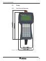
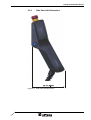
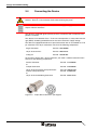
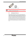
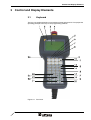
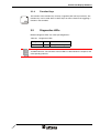
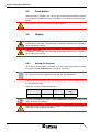
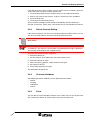
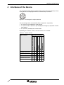
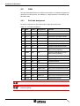
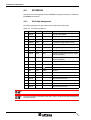
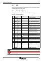
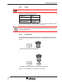
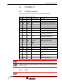
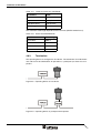
User Manual
TesiMod Hand-held Terminal HT06
Part Number:
80860.684
Version:
3
Date:
19.01.2006
Valid for:
HT06/0203/xxx/00xxx
HT06/0203/xxx/03xxx
HT06/0803/xxx/00xxx
HT06/0803/xxx/03xxx
HT06/0903/xxx/00xxx
HT06/0903/xxx/03xxx
HT06/1603/xxx/00xxx
HT06/1603/xxx/03xxx
HT06/1803/xxx/00xxx
HT06/1803/xxx/03xxx
with external download- / upload interface
Version
1
2
3
Date
11.11.1999
16.10.2000
19.01.2006
Modifications
First Edition
Interface Variants Enlarged
External Download- / Upload Interface
This manual, including all illustrations contained herein, is copyright protected. Use of this manual by any third
party in departure from the copyright provision is forbidden. No part of this manual may be reproduced, translated or electronically or photographically archived or altered without the express written consent from Sütron
electronic GmbH. Violations shall be cause for damage liability.
Sütron electronic reserves the right to make any changes that contribute to technical improvement.
Gesamtinhaltsverzeichnis
1
Important Notes ....................................................................................................... 1-1
1.1
2
3
1.1.1
General Symbols ................................................................................. 1-1
1.1.2
Specific Symbols ................................................................................. 1-1
1.2
Safety Notes ............................................................................................. 1-2
1.3
Intended Use............................................................................................. 1-2
1.4
Target Group............................................................................................. 1-2
Design and Commissioning ..................................................................................... 2-1
2.1
Unpacking the Device ............................................................................... 2-1
2.2
Mounting the Device ................................................................................. 2-1
2.3
Design....................................................................................................... 2-2
2.3.1
Front View with Dimensions ................................................................ 2-2
2.3.2
Side View with Dimensions.................................................................. 2-3
2.4
Connecting the Device.............................................................................. 2-4
2.5
Switching the Device on............................................................................ 2-5
2.6
Identification.............................................................................................. 2-6
Control and Display Elements ................................................................................. 3-1
3.1
4
Symbols .................................................................................................... 1-1
Keyboard................................................................................................... 3-1
3.1.1
Editing Keys ......................................................................................... 3-2
3.1.2
Control Keys ........................................................................................ 3-3
3.1.3
Special Keys ........................................................................................ 3-4
3.1.4
Function Keys ...................................................................................... 3-5
3.2
Diagnostics LEDs...................................................................................... 3-5
3.3
User Mode Switch..................................................................................... 3-6
3.4
Stop Push-button / Emergency Stop Button ............................................. 3-7
3.5
Push-button............................................................................................... 3-8
3.6
Display ...................................................................................................... 3-8
3.6.1
Setting the Contrast ............................................................................. 3-8
3.6.2
Default Contrast Setting....................................................................... 3-9
3.6.3
Character Attributes ............................................................................. 3-9
3.6.4
Fonts .................................................................................................... 3-9
Interfaces of the Device ........................................................................................... 4-1
4.1
4.1.1
4.2
4.2.1
RS232 (Download / Upload) ..................................................................... 4-2
Pin Assignment .................................................................................... 4-2
RS232 (Communication)........................................................................... 4-3
Pin/Cable Assignment ......................................................................... 4-3
i
Gesamtinhaltsverzeichnis
4.3
4.3.1
Pin/Cable Assignment.......................................................................... 4-4
4.3.2
Termination .......................................................................................... 4-5
4.4
INTERBUS ................................................................................................ 4-6
4.4.1
Pin/Cable Assignment.......................................................................... 4-6
4.4.2
Termination .......................................................................................... 4-7
4.4.3
Diagnostics .......................................................................................... 4-7
4.5
MPI............................................................................................................ 4-8
4.5.1
Pin/Cable Assignment.......................................................................... 4-8
4.5.2
Cable.................................................................................................... 4-9
4.5.3
Termination .......................................................................................... 4-9
4.5.4
Diagnostics ........................................................................................ 4-10
4.6
PROFIBUS-DP........................................................................................ 4-11
4.6.1
Pin/Cable Assignment........................................................................ 4-11
4.6.2
Cable.................................................................................................. 4-11
4.6.3
Termination ........................................................................................ 4-12
4.6.4
Diagnostics ........................................................................................ 4-13
4.7
5
CAN........................................................................................................... 4-4
Shielding D-SUB Connectors.................................................................. 4-13
Maintenance and Servicing......................................................................................5-1
5.1
Maintenance Interval................................................................................. 5-1
5.2
Front Panel................................................................................................ 5-1
5.3
Fuse .......................................................................................................... 5-1
5.4
Battery....................................................................................................... 5-1
5.4.1
Changing the Battery ........................................................................... 5-2
5.4.2
Battery Disposal ................................................................................... 5-2
6
Technical Data .........................................................................................................6-1
7
Ordering Data...........................................................................................................7-1
A
Index ....................................................................................................................... A-1
ii
Important Notes
1
Important Notes
1.1
Symbols
The symbols in this manual are used to draw your attention on notes and dangers.
1.1.1
General Symbols
Danger
This symbol is used to refer to instructions which, if ignored or not carefully followed
could result in personal injury.
Note
This symbol indicates application tips or supplementary notes.
Reference to source of information
This symbol refers to detailed sources of information on the current topic.
1.1.2
Specific Symbols
The following symbols indicate specific dangers which could result in damage to
equipment or personal injury or even up to the death of the operator.
Danger - Electric Shock
Danger - Corrosive
Danger - Toxic
Danger - Explosive
Danger - Fire
Danger - Infrared Light
Danger - Electrostatic Charge
1-1
Important Notes
1.2
Safety Notes
–
Read this manual carefully before using the operating device. Keep this manual
in a place where it is always accessible to all users.
–
Proper transportation, handling and storage, placement and installation of this
product are prerequisites for its subsequent flawless and safe operation.
–
This user manual contains the most important information for the safe operation
of the device.
–
The user manual, in particular the safety notes, must be observed by all personnel working with the device.
–
Observe the accident prevention rules and regulations that apply to the operating
site.
–
Installation and operation must only be carried out by qualified and trained personnel.
1.3
Intended Use
–
The device is designed for use in the industry.
–
The device is state-of-the art and has been built to the latest standard safety requirements. However, dangerous situations or damage to the machine itself or
other property can arise from the use of this device.
–
The device fulfills the requirements of the EMC directives and harmonized European standards. Any modifications to the system can influence the EMC behavior.
This is a class A device. This device may cause radio interference in residential areas. In this case, the user may be required to introduce appropriate countermeasures, and to bear the cost of same.
1.4
Target Group
All configuration, programming, installation, commissioning, operating and maintenance work in connection with the automation system must be performed by trained
personnel only (e.g. qualified electricians, electrical engineers, etc.).
The configuration and programming personnel must be familiar with the safety concepts of automation technology.
The operating personnel must have been trained in handling the controller and be
familiar with the operating instructions.
The installation, commissioning and maintenance personnel must have an education
which entitles them to work on automation systems.
1-2
Design and Commissioning
2
Design and Commissioning
2.1
Unpacking the Device
Unpack all parts carefully and check the contents for any visible damage in transit.
Also check whether the shipment matches the specifications on your delivery note.
If you notice damages in transit or discrepancies, please contact our sales department immediately.
2.2
Mounting the Device
The operating device is optional equipped with a hook and a magnet. You can put
the operating device to a suitable position with these mounting options.
2-1
Design and Commissioning
2-2
2.3
Design
2.3.1
Front View with Dimensions
Figure 2-1
Front view with dimensions
Design and Commissioning
2.3.2
Side View with Dimensions
Figure 2-2
Side View with Dimensions
2-3
Design and Commissioning
2.4
Connecting the Device
Hazardous voltages can exist inside electrical installations that can pose a danger to
humans. There is a risk of electric shock when touching live parts!
For information on the pin or core numbers for the supply voltage, please refer to the
chapter "Device Interfaces".
The device is protected against polarity reversal. The device will not operate if the
polarity is incorrect.
This device is in Protection Class I. To ensure safe operation, a safety extra-low voltage (SELV) according to DIN EN 61131 must be used for the supply voltage.
The device is equipped with either an open cable end or with an assembled 12 or 16
pin connector. The 16 pin connectors consist of the following components:
Angle Connector
Part-No. 7301500000
16 pin Insert for Pins
Part-No. 7003916101
Crimp pin
Part-No. 7010901001
To connect a device with a 16 pin connector, you need a suitable connector which
consists of the following components:
Device Connector
or
Coupler Connector
Part-No. 7471500000
16 pin Insert for Female Crimp Connector
Female Crimp Connector
or
16 pin Insert for Soldering Connector
Part.-No. 7003916102
Part-No. 7010901002
Figure 2-3
2-4
Part-No. 7201500000
Part-No. 7001916104
16 pin device connector / pin diagram
Design and Commissioning
Figure 2-4
16 pin coupler connector / pin diagram
The listed parts can be obtained from Hummel Metall- und Kunststofftechnik GmbH.
The crimp pins must be processed with a crimping tool. The tool is also obtainable at
Hummel Metall- und Kunststofftechnik GmbH.
2.5
Switching the Device on
After you applied the supply voltage, a system test is carried out during which the
modules in the operating device are tested and initialized. All status LEDs are activated for a short time. A number of system and error messages can be output by the
system test. If the application memory contains a valid project, the first mask, i.e. the
„Start mask“ or the mask defined in the TSwin language parameters as the Start-up
mask appears on the display. A beep also sounds by the integrated loudspeaker.
The „Start mask“ is displayed for 5 seconds. This is a fixed time setting. After this time
has elapsed, the „Main mask“ or the mask defined in the language parameters as the
Main mask appears on the display. This is the first mask of the operator guidance.
When you touch the display while the „Start mask“ is displayed, the „Setup mask“ appears. In this mask you define the parameters for the interfaces and the operating
device.
2-5
Design and Commissioning
2.6
Identification
You can identify the operating device by the nameplate on the rear.
Figure 2-5
Nameplate (example)
1
Order Number
2
Firmware Version (Version on Delivery)
3
Voltage and Current
4
Serial Number
Depending on the size of the display, you will be able to read various types of information as the operating device is initialized: clock frequency, application memory
size, current firmware version, TSwin version, project name, time, date, number of
compilation runs and a random number.
Because the initialization mask is visible only for a few seconds there is a possibility
to represent this mask for a longer time period.
1. Hold down an arbitrary key at the operating device to generate an error message.
2. Read the firmware version now.
3. Release the key to complete the initialization procedure of the operating device.
2-6
Control and Display Elements
3
Control and Display Elements
3.1
Keyboard
The keys are positioned under an environmental-proof polyester foil. You project the
operating principle of the keys in the programming software.
Figure 3-1
Front view
3-1
Control and Display Elements
1. Enclosure
2. Nameplate
3. Display
4. Emergency Stop Button (Option)
5. Diagnostics LED Vcc
6. Diagnostics LED RC
7. Diagnostics LED BA
8. Diagnostics LED RD
9. Right Push-button on the Side (Option)
10. Status LED Function Keys F1 to F8
11. Function Keys F1 to F8
12. Status LED Data Release
13. Special Key Data Release
14. Editing Key Plus
15. Editing Key Minus
16. Special Key Enter
17. Special Key Delete
18. Status LED Help
19. Special Key Help
20. Control Key Page Down
21. Cursor Keys Right, Left, Up, Down
22. Special Key Acknowledge
23. Cursor Key Home
24. Editing Key 0 to 9, Alphabet
25. Editing Key Decimal Point
26. Left Push-button on the Side (Option)
3.1.1
Editing Keys
The key 0 and ()° is used for changing data in the editor. The (, ) and ° characters
can be entered when configuring the Shift or ShiftCase system variables.
The key 1 and STU is used for changing data in the editor. The characters S, T and
U can be entered when configuring the Shift or ShiftCase system variables.
The key 2 and VWX is used for changing data in the editor. The characters V, W and
X can be entered when configuring the Shift or ShiftCase system variables.
The key 3 and YZ% is used for changing data in the editor. The characters Y, Z and
% can be entered when configuring the Shift or ShiftCase system variables.
3-2
Control and Display Elements
The key 4 and JKL is used for changing data in the editor. The characters J, K and
L can be entered when configuring the Shift or ShiftCase system variables.
The key 5 and MNO is used for changing data in the editor. The characters M, N and
O can be entered when configuring the Shift or ShiftCase system variables.
The key 6 and PQR is used for changing data in the editor. The characters P, Q and
R can be entered when configuring the Shift or ShiftCase system variables.
The key 7 and ABC is used for changing data in the editor. The characters A, B and
C can be entered when configuring the Shift or ShiftCase system variables.
The key 8 and DEF is used for changing data in the editor. The characters D, E and
F can be entered when configuring the Shift or ShiftCase system variables.
The key 9 and GHI is used for changing data in the editor. The characters G, H and
I can be entered when configuring the Shift or ShiftCase system variables.
The key Decimal point and :?! is used for changing data in the editor. The characters :, ? and ! can be entered when configuring the Shift or ShiftCase system variables.
The key Plus and <=> is used for changing data in the editor. The characters <, =
and > can be entered when configuring the Shift or ShiftCase system variables.
The key Minus and \*/ is used for changing data in the editor. The characters \, * and
/ can be entered when configuring the Shift or ShiftCase system variables.
3.1.2
Control Keys
The key Cursor left can be programmed to directly select adjacent I/O masks. In the
editor, it moves the cursor within a variable to the left by one character (character selection).
3-3
Control and Display Elements
The key Cursor right can be programmed to directly select adjacent nodes and I/O
masks. In the editor it moves the cursor one character to the right (character selection).
The key Cursor up can be programmed to directly select adjacent nodes and I/O
masks. In the editor it moves the cursor up one variable (variable selection).
The key Cursor down can be programmed to directly select adjacent I/O masks. In
the editor, it moves the cursor downwards to the next variable (variable selection).
The key Cursor home can be programmed to directly select higher-level nodes and
I/O masks. In the editor it returns the cursor to the first input variable position.
The key Page is used to page through tables, recipes and messages. The functionality corresponds to the system variable TabPgDn. The key allows data content towards the bottom of the table to be viewed.
3.1.3
Special Keys
The key Help always displays the current help text (online help). The help key LED
flashes when a system message is pending. The system message is always displayed in plain-text.
The key Data Release is used to switch from the menu into the editor. The integrated
LED lights up in the editing mode if the external data release has been set. When the
Data Release key is pressed within the editor, the editing mode is exited.
The key Enter is used to conclude data entry. When pressed while in the Startup
Mask, the key switches into the Setup Mask.
The key Delete deletes the character beneath the cursor in the editor. Removes the
selected messages from the data memory.
The key Acknowledge is used as acknowledge key for the message system.
3-4
Control and Display Elements
3.1.4
Function Keys
The function of the function keys is freely assignable (with soft key functions). The
function keys can be used either as direct keys for menu control or for triggering a
function in the controller.
3.2
Diagnostics LEDs
Different diagnosis LEDs are at the operating device.:
Table 3-1
Diagnostics LEDs
Designation
Color
Function
Vcc
Green
Voltage Monitoring
The Diagnostics -LEDs RC, BA and RD are used with INTERBUS, PROFIBUS-DP
and MPI interfaces. The functions of these LEDs are described in the chapter of the
corresponding interface
3-5
Control and Display Elements
3.3
User Mode Switch
When opening and closing the operating device, you must take care not to damage
the seal and make sure that it always sits in the slot provided.
Electrostatic discharge can damage electronic components! Observe the ESD protective measures!
The user mode switch is positioned at the bottom right in the keyboard circuit board
in the top shell of the operating device. To operate the user mode switch, proceed as
follows:
1. Disconnect the operating device from the supply voltage.
2. Remove the screws on the rear of the housing and lift off the housing.
3. Set the desired operating mode (see table).
4. After setting the operating mode, place the housing rear panel back onto the device.
5. Carefully screw the screws tightly into the rear panel of the housing again.
6. Connect the operating device with the supply voltage.
Figure 3-2
Position of user mode switch
The switch positions for ON or OFF are printed onto the termination switch.
Table 3-2
User mode switch
S1
S2
S3
S4
I
X
–
–
Standard mode with PLC (default upon delivery)
I
X
I
–
Standard mode without PLC
I
–
–
I
Activate download (deletes application memory) and default contrast / default brightness setting
I
–
I
I
Activate upload
Legend for table:
I = Switch ON
– = Switch OFF
X = Any switch position
3-6
Operating Mode
Control and Display Elements
3.4
Stop Push-button / Emergency Stop Button
The device can be fitted with an optional STOP push-button or an emergency stop
button.
The STOP push-button on the operating device ensures that the system to be monitored is shut down safely in accordance with EN 60204-1:1997, Paragraph 9.2.5.3.
The stop function can be a Category 0, 1 or 2 stop according to EN 60204-1:1997,
Paragraph 9.2.2 and must be defined according to the risk assessment.
Therefore, the stop function of the operating device can be used for a safe machine
stop as well as for looping into the emergency stop circuit of the system to be monitored.
The signals of the STOP push-button use different circuits in the two versions of the
linkbox. In the case of the linkbox with an emergency stop function, the signals control the stop circuit or emergency stop circuit of the system to be monitored. If no
hand-held operating device is connected, the stop circuit or emergency stop circuit,
respectively, is closed. In the linkbox without an emergency stop function, on the
other hand, the signals of the stop circuit or emergency stop circuit are sent via the
STOP push-button. If no hand-held operating device is connected, the stop circuit or
emergency stop circuit, respectively, of the system to be monitored is open.
The term "stop looping" has the following meaning: The stop circuit or emergency
stop circuit, respectively, of the system to be monitored is looped through the linkbox
and not interrupted, irrespective of whether the hand-held operating device is connected to the linkbox (and the STOP push-button has not been operated) or not. This
functionality is only available with the linkbox with an emergency stop function.
Warning!
If using a hand-held operating device with an emergency stop button, you must ensure that the connecting cable is securely installed.
A hand-held operating device that is not connected to the machine must be stored
out of sight of the user!
Bear in mind that the nearest emergency stop will be activated in the event of danger.
If it does not work because it is not connected, this could have fatal consequences!
Warning!
If the hand-held operating device is equipped with a STOP push-button but it is not
connected to the linkbox, a stop can not be triggered using the hand-held operating
device – the STOP push-button of the hand-held operating device is ineffective!
Install stationary emergency stop buttons that are available at all times on the system
to be monitored.
Warning!
If the stop circuit has been implemented as a Category 0 or 1 stop, the stop function
must be effective regardless of the operating mode. A Category 0 stop must have priority. The releasing of the STOP push-button must NOT lead to hazardous conditions
(also see EN 60204-1:1997 Chapter 9.2.5.3).
The stop function is not a substitute for safety devices.
3-7
Control and Display Elements
3.5
Push-button
Optionally one push-button each is on the right and left side of the operating device.
It is possible to start different orders or conditions at the machine with these pushbuttons.
The connection must be carried out with little induction.
3.6
Display
Danger - Toxic!
If the display is damaged, avoid touching, swallowing or breathing in the liquids or
gases which may leak out!
Danger - Corrosive!
If the display is damaged, avoid touching, swallowing or breathing in the liquids or
gases which may leak out!
The operating device is equipped with a LC-Display.
3.6.1
Setting the Contrast
To be able to set the contrast, you need to use the programming software to setup
the system variable LcdContrast in a screen of your choice.
To do so, follow the instructions listed in the programming software's help topic "How
do I specify the contrast / brightness setting for the operating device".
In the programming software, enter the following values as lower and upper limits for
the representation type.
Table 3-3
Values for representation type
System Variable
LcdContrast
Lower Limit
Upper Limit
Default Setting
- 25
+ 125
+ 25
If you do not configure the system variable LcdContrast, the default setting is used
when the device is initialized.
Adjust the contrast to the surrounding conditions at reached operating temperature
to be able to read the display optimally.
3-8
Control and Display Elements
If you did set up the system variable, you can set the contrast as follows. Open the
screen where you set up the system variable and:
1. Press the Data Release key if the data release is not automatically active.
2. Enter a new value for the contrast. To do so, use the keys Plus and Minus.
3. Press the Enter key.
4. Finally press the Data Release key.
The new contrast setting becomes effective immediately after the Enter key is
pressed. If necessary, repeat steps 2 and 3 until you are satisfied with the contrast.
3.6.2
Default Contrast Setting
If the contrast setting is such that it is no longer possible to read the masks, you can
use the user mode switch to reset the contrast to the default value.
For the table with the switch positions of the user mode switch, see chapter "User
Mode Switch".
The switch position for the default contrast is identical with the „Activate download
via hardware“. The contrast is reset before a corresponding message is displayed.
The warning will be displayed in a legible manner.
To restore the default contrast / brightness:
1. Switch the device off.
2. Set the switches S1 and S4 of the user mode switch to ON.
3. Switch the device on again.
4. When the warning appears, switch the device off again.
5. Set switch S4 to OFF.
6. Then switch the device on again.
The application will not be lost.
3.6.3
Character Attributes
The following character attributes can be displayed on the device:
–
Normal
–
Flashing
–
Underlined
–
Inverse
3.6.4
Fonts
You are able to use the Windows character sets. Further you can use the font "Normal" and the font "Zoom" or create and use your own character sets.
3-9
Control and Display Elements
3-10
Interfaces of the Device
Interfaces of the Device
The standard operating device is supplied with an open cable end. Optionally, the operating device can be equipped with an assembled 16 pin connector.
Figure 4-1
Pin diagram for 16 pin connector
The connecting cable is constructed of three components, respectively.
1. 3 x 0,5 mm² (not shielded) for supply voltage
2. 2 x 0,5 mm² and 6 x 0,25 mm² (not shielded) for emergency stop button and the
push-buttons
3. 5 x 0,25 mm² (shielded) for communication
Depending on the device variant, several interfaces are available:
Table 4-1
Device variants
CAN
INTERBUS
MPI
PROFIBUS-DP
Available Interfaces
RS232c
Order Number
RS232c (Download / Upload)
4
HT06/02xx/xxx/xxxxx
X
X
-
-
-
-
HT06/09xx/xxx/xxxxx
X
-
X
-
-
-
HT06/18xx/xxx/xxxxx
X
-
-
X
-
-
HT06/16xx/xxx/xxxxx
X
-
-
-
X
-
HT06/08xx/xxx/xxxxx
X
-
-
-
-
X
4-1
Interfaces of the Device
4.1
RS232 (Download / Upload)
The interface is only designed to be used for downloads and uploads because the
interface is not electrically isolated.
To carry out a download or an upload, proceed as follows:
1. Carefully unscrew and remove the protective cap (see figure) of the download/
upload interface.
2. Plug the cable onto the interface of the operating device.
3. Connect the other end of the cable with the serial interface of the PC.
4. Now carry out the download or upload.
5. After the download/upload is complete, remove the cable from the interfaces
again.
6. Carefully tighten the protective cap for the download/upload interface again.
Figure 4-2
Position of download/upload interface
4.1.1
Pin Assignment
Connector in the operating device: 5 pin female connector - Binder series 702.
Table 4-2
Pin assignment of the RS232 interface
Pin
Designation
Function
1
TD
Transmitted Data
2
RD
Received Data
3
CTS
Clear to Send
4
RTS
Request to Send
5
GND
Ground
You can obtain an assembled cable directly from Sütron electronic.
4-2
Interfaces of the Device
4.2
RS232 (Communication)
The interface is suitable to establish a point-to-point connection.
4.2.1
Pin/Cable Assignment
Pin/cable assignment for open cable end or 16 pin device connector.
Table 4-3
Pin/cable assignment
Pin
Wire
ø mm²
Design.
Function
-
Shield
-
-
Overall Cable Shield
1
RDBU
0,25
S
Push-button Left, Make Contact
11
PK
0,25
S
Push-button Left, Make Contact
2
WHGN
0,25
S
Push-button Right, Make Contact
12
OR
0,25
S
Push-button Right, Make Contact
3
BU
0,5
O
Emergency Stop Brake Contact
4
BN
0,5
O
Emergency Stop Brake Contact
5
WHYE
0,25
O/S
Emergency Stop Brake Contact / Make
Contact (Optional)
6
BNGN
0,25
O/S
Emergency Stop Brake Contact / Make
Contact (Optional)
8
BK
0,5
0V
Supply Voltage 0 VDC
9
VT
0,5
+ 24 V
Supply Voltage 24 VDC
10
YE
0,5
7
GR
0,25
GND
Ground
13
WH
0,25
TD
Transmitted Data
14
BN
0,25
RTS
Request to Send
-
Shield
-
-
Shield Communication
15
RD
0,25
CTS
Clear to Send
16
GN
0,25
RD
Received Data
-
Shield
-
-
Shield Communication
Low-Noise Ground
Grey underlayed entries are only optionally available.
For operating devices with open cable ends, make sure to connect the shield with the
protective ground.
4-3
Interfaces of the Device
4.3
CAN
The opto decoupled interface for CAN bus connections is available to integrate the
device into a CAN structure. The CAN bus is a high speed bus in accordance with
ISO-DIS 11898.
4.3.1
Pin/Cable Assignment
Pin/cable assignment for open cable end or 16 pin device connector.
Table 4-4
Pin/cable assignment
Pin
Wire
ø mm²
Designation
Function
-
Shield
-
-
Overall Cable Shield
1
RDBU
0,25
S
Push-button Left, Make Contact
11
PK
0,25
S
Push-button Left, Make Contact
2
WHGN
0,25
S
Push-button Right, Make Contact
12
OR
0,25
S
Push-button Right, Make Contact
3
BU
0,5
O
Emergency Stop Brake Contact
4
BN
0,5
O
Emergency Stop Brake Contact
5
WHYE
0,25
O/S
Emergency Stop Brake Contact /
Make Contact (Optional)
6
BNGN
0,25
O/S
Emergency Stop Brake Contact /
Make Contact (Optional)
8
BK
0,5
0V
Supply Voltage 0 VDC
9
VT
0,5
+ 24 V
Supply Voltage 24 VDC
10
YE
0,5
7
GR
0,25
GND
Ground
13
WH
0,25
CANH (OUT)
CAN_H Bus Line (Dominant HIGH)
14
BN
0,25
CANL (OUT)
CAN_L Bus Line (Dominant LOW)
-
Shield
-
-
Shield Communication
15
RD
0,25
CANH (IN)
CAN_H Bus Line (Dominant HIGH)
16
GN
0,25
CANL (IN)
CAN_L Bus Line (Dominant LOW)
-
Shield
-
-
Shield Communication
Low-Noise Ground
Grey underlayed entries are only optionally available.
For operating devices with open cable ends, make sure to connect the shield with the
protective ground.
4-4
Interfaces of the Device
4.3.2
Termination
The operating device is configured as a participant. At use as last device you have
to use a terminating resistor (RAb=120 ohms) between the wires WH and BN.
Figure 4-3
Operating device as participant
Figure 4-4
Operating device as last device
4-5
Interfaces of the Device
4.4
INTERBUS
The device can be integrated into the INTERBUS using the interfaces available for
INTERBUS connections.
4.4.1
Pin/Cable Assignment
Pin/cable assignment for open cable end or 16 pin device connector.
Table 4-5
Pin/cable assignment
Pin
Wire
ø mm²
Design.
Function
-
Shield
-
-
Overall Cable Shield
1
RDBU
0,25
S
Push-button Left, Make Contact
11
PK
0,25
S
Push-button Left, Make Contact
2
WHGN
0,25
S
Push-button Right, Make Contact
12
OR
0,25
S
Push-button Right, Make Contact
3
BU
0,5
O
Emergency Stop Brake Contact
4
BN
0,5
O
Emergency Stop Brake Contact
5
WHYE
0,25
O/S
Emergency Stop Brake Contact / Make
Contact (Optional)
6
BNGN
0,25
O/S
Emergency Stop Brake Contact / Make
Contact (Optional)
8
BK
0,5
0V
Supply Voltage 0 VDC
9
VT
0,5
+ 24 V
Supply Voltage 24 VDC
10
YE
0,5
7
GR
0,25
GND
Ground
13
WH
0,25
DI1
Data Input
14
BN
0,25
/DI1
Data Input, Inverted
-
Shield
-
-
Shield Communication
15
RD
0,25
DO1
Data Output
16
GN
0,25
/DO1
Data Output, Inverted
-
Shield
-
-
Shield Communication
Low-Noise Ground
Grey underlayed entries are only optionally available.
For operating devices with open cable ends, make sure to connect the shield with the
protective ground.
4-6
Interfaces of the Device
4.4.2
Termination
You only can use the operating device as last device.
Figure 4-5
Operating device as last device
4.4.3
Diagnostics
There are diagnostics LEDs at the operating device. The LEDs show the states of
the bus system.
The diagnostics LEDs on the operating device has the following functions:
Table 4-6
Functions of the INTERBUS diagnostics LEDs
Designation
Color
State
Function
RC
Green
On
Remote Bus Check
BA
Green
On
Bus Active
Off
Bus Not Active
On
Remote Bus Inactive
RD
Red
4-7
Interfaces of the Device
4.5
MPI
The device can be integrated into a Siemens MPI bus structure using the interface
available for Siemens MPI connections.
4.5.1
Pin/Cable Assignment
Pin/cable assignment for open cable end or 16 pin device connector.
Table 4-7
Pin/cable assignment
Pin
Wire
ø mm²
Designation
Function
-
Shield
-
-
Overall Cable Shield
1
RDBU
0,25
S
Push-button Left, Make Contact
11
PK
0,25
S
Push-button Left, Make Contact
2
WHGN
0,25
S
Push-button Right, Make Contact
12
OR
0,25
S
Push-button Right, Make Contact
3
BU
0,5
O
Emergency Stop Brake Contact
4
BN
0,5
O
Emergency Stop Brake Contact
5
WHYE
0,25
O/S
Emergency Stop Brake Contact
/ Make Contact (Optional)
6
BNGN
0,25
O/S
Emergency Stop Brake Contact
/ Make Contact (Optional)
8
BK
0,5
0V
Supply Voltage 0 VDC
9
VT
0,5
+ 24 V
Supply Voltage 24 VDC
10
YE
0,5
7
GR
0,25
DGND
Data Transmission Potential
13
WH
0,25
CNTR-N
Repeater Control Signal Minus
14
BN
0,25
nc
Not Connected
-
Shield
-
-
Shield Communication
15
RD
0,25
RxD/TxD-N
Received Data / Transmitted
Data Minus
16
GN
0,25
RxD/TxD-P
Received Data / Transmitted
Data Plus
-
Shield
-
-
Shield Communication
Low-Noise Ground
Grey underlayed entries are only optionally available.
For operating devices with open cable ends, make sure to connect the shield with the
protective ground.
4-8
Interfaces of the Device
4.5.2
Cable
Any cable that conforms with the following parameters can be used:
Table 4-8
Cable characteristics MPI
Parameters
Value
Loop Resistance
110 Ohm/km
Capacitance
30 nF/km
Surge Impedance
150 Ohm
The maximum length of one segment is 50 m which cannot be exceeded. This 50 m
applies from the first node to the last node in the segment.
For further information on the installation, please refer to the Siemens manual "SIMATIC S7-400 and M7-400 Programmable Controllers Hardware and Installation,
6ES7498-8AA03-8BA0".
4.5.3
Termination
The operating device is configured as last device. The termination is inside the device and can not be switched off. At operation as a participant you have to use repeaters.
Figure 4-6
Operating device as last device
Figure 4-7
Operating device as participant with repeater
4-9
Interfaces of the Device
4.5.4
Diagnostics
There is a diagnostics LED at the operating device. The LED shows the state of the
bus system.
The diagnostics LED on the operating device has the following function:
Table 4-9
4-10
Function of the MPI diagnostics LED
Color
State
Function
Green
On
Data exchange
Interfaces of the Device
4.6
PROFIBUS-DP
4.6.1
Pin/Cable Assignment
Pin/cable assignment for open cable end or 16 pin device connector.
Table 4-10
Pin/cable assignment
Pin
Wire
ø mm²
Designation
Function
-
Shield
-
-
Overall Cable Shield
1
RDBU
0,25
S
Push-button Left, Make Contact
11
PK
0,25
S
Push-button Left, Make Contact
2
WHGN
0,25
S
Push-button Right, Make Contact
12
OR
0,25
S
Push-button Right, Make Contact
3
BU
0,5
O
Emergency Stop Brake Contact
4
BN
0,5
O
Emergency Stop Brake Contact
5
WHYE
0,25
O/S
Emergency Stop Brake Contact /
Make Contact (Optional)
6
BNGN
0,25
O/S
Emergency Stop Brake Contact /
Make Contact (Optional)
8
BK
0,5
0V
Supply Voltage 0 VDC
9
VT
0,5
+ 24 V
Supply Voltage 24 VDC
10
YE
0,5
7
GR
0,25
DGND
Data Transmission Potential
13
WH
0,25
CNTR-P
Repeater Control Signal Plus
14
BN
0,25
nc
Not Connected
-
Shield
-
-
Shield Communication
15
RD
0,25
RxD/TxD-N
Received Data / Transmitted Data
Minus
16
GN
0,25
RxD/TxD-P
Received Data / Transmitted Data
Plus
-
Shield
-
-
Shield Communication
Low-Noise Ground
Grey underlayed entries are only optionally available.
For operating devices with open cable ends, make sure to connect the shield with the
protective ground.
4.6.2
Cable
Any PROFIBUS-DP-approved cables specified in the EN 50170 as cable type A can
be used.
4-11
Interfaces of the Device
Table 4-11
Cable characteristics PROFIBUS
Parameters
Value
Impedance
136 to 165 Ohm
Capacitance
< 30 pf/m
Loop Resistance
110 Ohm/km
Wire Gauge
0.64 mm
The maximum cable length depends on the baud rate (DIN EN 19245 Part 3).
Table 4-12
Baud rate PROFIBUS-DP
Baud Rate
Cable Length
187.5 kBit/s
1000 m
500 kBit/s
400 m
1500 kBit/s
200 m
3000 to 12000 kBit/s
100 m
4.6.3
Termination
The operating device is configured as last device. The termination is inside the device and can not be switched off. At operation as a participant you have to use repeaters.
4-12
Figure 4-8
Operating device as last device
Figure 4-9
Operating device as participant with repeater
Interfaces of the Device
4.6.4
Diagnostics
There is a diagnostics LED at the operating device. The LED shows the state of the
bus system.
The diagnostics LED on the operating device has the following function:
Table 4-13
Function of the PROFIBUS-DP diagnostics LED
Designation
Color
State
Function
BA
Green
On
Data exchange
4.7
Shielding D-SUB Connectors
You must shield D-SUB connectors as follows:
Figure 4-10
Shielding D-SUB connectors
1
D-SUB connector
2
Shield
3
Cable clip
4
Cable
The shield must be folded back into a flat position over the cable sheath.
When fastening the cable with the cable clip, as much of the shielding as possible
must be in contact with the housing and sufficient strain relieve must be ensured.
4-13
Interfaces of the Device
4-14
Maintenance and Servicing
5
Maintenance and Servicing
5.1
Maintenance Interval
The following maintenance intervals are recommended for this operating device:
Table 5-1
Maintenance work
Interval
Changing the Battery
4 Years
5.2
Front Panel
Only use a damp cloth to remove any dirt from the front panel.
5.3
Fuse
The semiconductor fuse cannot be replaced!
A semiconductor fuse is used to protect the device. Once the fuse has been tripped,
the device must be disconnected from the supply voltage to allow the semiconductor
fuse to regenerate. At an ambient temperature of 20 °C (68 °F), the regeneration
takes approximately 20 seconds. The higher the ambient temperature, the longer the
regeneration takes.
5.4
Battery
The built-in battery preserves the data in the CMOS-RAM and supplies the real-time
clock. The minimum battery life is 5 years, even under unfavorable operating conditions. When the battery runs down, the message „Change battery“ is generated automatically.
We recommend you change the battery approximately every 4 years as part of the
regular maintenance work. A prepared battery including connector can be obtained
directly from Sütron electronic.
If the „Change battery“ message is detected too late, e.g. the real-time clock stopped
or shows the wrong date, data in the CMOS-RAM may have already been lost. For
this reason, after changing a battery, always check data such as passwords that can
be modified, parameters in the system variables, recipe data sets and entries in the
message system.
5-1
Maintenance and Servicing
5.4.1
Changing the Battery
Batteries must only be changed by authorized and trained experts!
For changing the battery you may only use replacement batteries of
Sütron electronic.
Electrostatic discharge can damage electronic components! Observe the ESD protective measures!
Do not throw lithium batteries into fire, do not heat to 100 °C or higher and do not
recharge. Danger - Explosive!
Do not open lithium batteries. Danger - Toxic!
When opening and closing the operating device, you must take care not to damage
the seal and make sure that it always sits in the slot provided.
To ensure that the data in the CMOS-RAM and the time are preserved, it is possible
to change the battery under operating voltage. Please note the safety notes!
1. Remove the screws on the rear of the housing and lift off the housing.
2. Remove the cable fastener which secures the battery.
3. Disconnect the battery connector and remove the dead battery.
4. Plug in the cable for the new battery.
5. Use a cable fastener to attach the new battery to the plastic support.
6. Place the rear panel back onto the device.
7. Carefully screw the screws tightly into the rear panel.
5.4.2
Battery Disposal
To prevent short circuitry in the collection boxes, insulate the poles of each battery
with insulation tape or put each single battery into a plastic bag.
You must always return old batteries to a dealer or to a returns depot set up for this
purpose by the public waste disposal body or a licensed battery dealer for recycling.
Only dispose of dead batteries in public or commercial collection boxes. The battery
is drained when the message „Change battery“ appears on the display of the device.
5-2
Technical Data
6
Technical Data
Keyboard
Type
Membrane Keyboard
Number of Keys
32 Keys
Switching Cycles
Approx. 6 Million
Actuator Travel
0.4 mm (0.016")
Key Area (Embossment)
13 mm x 13 mm (0.512" x 0.512")
Display Elements
4 Diagnostics LEDs
10 Status LEDs
Emergency Stop Button
According to EN 418
Type
Rafi RAFIX 16 1.30074.122
Lifetime
3 x 10⁴ Switching Cycles
Switching Element
Rafi RAFIX 16
Universal Switching Element 2NC or Optional 1NC + 1NO
Maximum Switching Current
250 mA 30 VAC, 250 mA 42 VDC
Lifetime
5 x 10⁵ Switching Cycles
Push-button
Type
APEM Series IS
Mechanical Lifetime
1 x 10⁶ Switching Cycles
Switching Element
1NO
Maximum Switching Current with Ohmic
Rated Current
400 mA 30 VAC, 100mA 50 VDC
Electrical Lifetime (Full Load)
5 x 10⁵ Switching Cycles
Display
Type
LCD
Resolution
126 x 64 Pixels
Reading Angle
90°
Default Brightness Setting
By User Mode Switch
LCD Lifetime
100,000 h
Half-Life Backlighting
100,000 h
6-1
Technical Data
Display
Lines
8
Characters/Line
21
Display Area (H x W)
40 mm x 72 mm (1.575" x 2.835")
Electrical Data
Supply Voltage
24 V DC (SELV in Accordance with DIN EN 61131)
Residual Ripple
10% Maximum
Minimum Voltage
19.2 V
Maximum Voltage
30.2 V
Power Consumption (Field Bus Device)
0.25 A
Connected Load
6W
Fuse
Semiconductor Fuse, Self-resetting
Protection Against Polarity Reversal
Integrated
Standard Interfaces
Variable Baud Rates and Data Formats
TTY / 20 mA
According to CL 2 and DIN 66 348 T1
Transmission Length: 0 - 1000 m (3280.84 ft.), Twisted Pair,
Shielded
Electrically Isolated
RS485
According to DIN 66259-4
Transmission Length: 0 - 1200 m (3937.01 ft.), Twisted Pair,
Shielded
Electrically Isolated
RS232c
According to DIN 66259 T1, CCITT V.28
Transmission Length: 0 - 15 m (49.21 ft.), Layer-stranded,
Shielded
Communication: Electrically Isolated
Download / Upload: Not Electrically Isolated
Field Bus Interfaces
Variable Baud Rates and Data Formats
CAN
According to ISO 11898
Electrically Isolated
DeviceNet
According to ISO 11898
Electrically Isolated
INTERBUS
Not Electrically Isolated
6-2
Technical Data
Field Bus Interfaces
SUCOnet K
Electrically Isolated
MPI
Electrically Isolated
PROFIBUS-DP
Electrically Isolated
Central Unit
Central Unit
Z84
Clock Frequency
10 MHz
Other Characteristics
Watchdog Timer, Real-Time Clock, Temperature Compensation of the Display, Battery Monitoring
Memory
Application Memory
256 KByte Flash
RAM
128 KByte Static CMOS-RAM, Battery-Backed
Connection System
Circular Connector M23, 16 pin
Connection Cable
Diameter
10.8 mm +/- 0.35 mm (0.425 +/- 0.014")
Weight
Approx. 172 g/m
Bending Radius fix lay
4 x Cable Diameter
Bending Radius loose lay
10 x Cable Diameter
UL Approved According to Style 20233, 80 °C (176 °F), 300V
Environmental Conditions
Operation
0 °C to 50 °C
Storage, Transport
-10 °C to 70 °C
Relative Air Humidity for Operation and
Storage
10% to 95%, No Condensation
Application Area
Degree of Pollution 2, Overvoltage Category II
6-3
Technical Data
Standards and Guidelines
Interference Immunity
EN 61000-4-2
EN 61000-4-3
EN 61000-4-4
EN 61000-4-5
EN 61000-4-6
Emitted Interference
EN 50081-1 Tab. A1
EN 50082-2
EN 55011 (PROFIBUS-DP and MPI: Limit Value Class A)
EN 55022 (PROFIBUS-DP and MPI: Limit Value Class A)
Equipment Requirements
EN 61131
Storage and Transportation
EN 61131 Part 2
Power Supply
EN 61131 Part 2
Electromagnetic Compatibility
89/336/EEC (Including all Applicable Amendments)
Degrees of Protection
EN 60529
Impact Load, Shocks
EN 60068 Part 2-27
Sinusoidal Vibrations
EN 60068 Part 2-6
Corrosion Protection
IEC 60068
Emergency Stop Button
EN 418
This is a class A device. This device may cause radio interference in residential areas. In this case, the user may be required to introduce appropriate countermeasures, and to bear the cost of same.
Housing
Type
ROSE Beluga 2200, Polyamide
Color
RAL7021
Impact Resistance
> 7 Nm to DIN 50014
Flammability
V2 to UL94
Measures (L x W x D)
Without Emergency Stop Button: Approx. 229 mm x 116.5 mm
x 125 mm (9.016" x 4.587" x 4.921")
With Emergency Stop Button: Approx. 253 mm x 116.5 mm x
125 mm (9.961" x 4.587" x 4.921")
Degree of Protection
IP54
Total Weight
Approx. 415 g without Cable
(Cable Weight Approx. 172 g/m)
6-4
Ordering Data
7
Ordering Data
Table 7-1
Accessories
Description
Part Number
5 Pin Download Cable
88311.020
USB-RS232 Converter for Downloads (In Connection With 88311.020
Only)
81215.000
Battery, Assembled With Cable And Connector
66694.000
Device Connector (Front Panel Mounting)
16 Pin Insert With Soldering Contacts
57320.000
57323.000
7-1
Ordering Data
7-2
A Index
A
Accessories....................................................... 7-1
B
Battery............................................................... 5-1
Battery disposal ................................................ 5-2
C
Cable
MPI ........................................................... 4-9
PROFIBUS-DP ....................................... 4-11
CAN .................................................................. 4-4
Changing the battery......................................... 5-2
Character attributes .......................................... 3-9
Character set
Normal ...................................................... 3-9
Windows ................................................... 3-9
Zoom......................................................... 3-9
Connecting........................................................ 2-4
Control keys ...................................................... 3-3
Data release.............................................. 3-4
Enter ......................................................... 3-4
Help........................................................... 3-4
Minus ........................................................ 3-3
Page.......................................................... 3-4
Plus ........................................................... 3-3
Keyboard........................................................... 3-1
L
LcdContrast....................................................... 3-8
M
Maintenance...................................................... 5-1
Maintenance interval ......................................... 5-1
Mounting ........................................................... 2-1
MPI.................................................................... 4-8
N
Nameplate......................................................... 2-6
O
D
Ordering data .................................................... 7-1
Default contrast setting ..................................... 3-9
Design............................................................... 2-2
Device variants ................................................. 4-1
Diagnostics
INTERBUS................................................ 4-7
MPI ......................................................... 4-10
PROFIBUS-DP ....................................... 4-13
Dimensions
Front view ................................................. 2-2
Side view .................................................. 2-3
Display .............................................................. 3-8
P
E
Editing keys....................................................... 3-2
Emergency stop button ..................................... 3-7
F
Firmware version .............................................. 2-6
Function keys.................................................... 3-5
Fuse .................................................................. 5-1
I
Identification...................................................... 2-6
Intended use ..................................................... 1-2
INTERBUS........................................................ 4-6
K
Key
Acknowledge ............................................ 3-4
Cursor down ............................................. 3-4
Cursor home ............................................. 3-4
Cursor left ................................................. 3-3
Cursor right ............................................... 3-4
Cursor up .................................................. 3-4
Pin- / cable assignment
CAN .......................................................... 4-4
INTERBUS................................................ 4-6
MPI............................................................ 4-8
PROFIBUS-DP ....................................... 4-11
RS232 ....................................................... 4-3
Pin assignment
RS232 (download / upload) ...................... 4-2
PROFIBUS-DP................................................ 4-11
Push-button....................................................... 3-8
R
RS232 (communication).................................... 4-3
RS232 (download / upload)............................... 4-2
S
Safety notes ...................................................... 1-2
Servicing ........................................................... 5-1
Setting the contrast ........................................... 3-8
Special keys ...................................................... 3-4
Standards.......................................................... 6-4
Stop pushbutton ................................................ 3-7
Switching on...................................................... 2-5
Symbols
General ..................................................... 1-1
Specific ..................................................... 1-1
T
Target group...................................................... 1-2
Technical data................................................... 6-1
Termination
CAN .......................................................... 4-5
A-1
INTERBUS................................................ 4-7
MPI............................................................ 4-9
PROFIBUS.............................................. 4-12
U
Unpacking ......................................................... 2-1
User mode switch.............................................. 3-6
A-2
Sütron electronic GmbH
Kurze Straße 29
D-70794 Filderstadt
Phone: 0049 711 / 77098-0
Fax:
0049 711 / 77098-60
E-mail: [email protected]
Internet: www.suetron.com