1
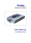
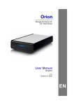
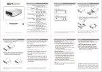
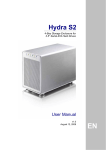
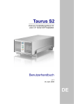
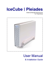
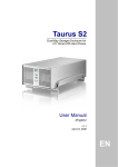
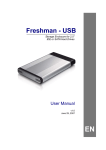
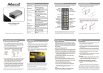
Hydra Super-S Combo 4-Bay RAID Storage Enclosure (3.5” SATA HDD) User Manual July 29, 2009 - v1.3 EN Hydra Super-S Combo Introduction 1 Introduction 1.1 System Requirements 1.1.1 PC Requirements Minimum Intel Pentium III CPU 500MHz, 128MB RAM eSATA equipped PC; Windows XP/Vista FireWire equipped PC; Windows XP/Vista USB 2.0 (USB 1.1) equipped PC; Windows XP/Vista 1.1.2 Mac Requirements Minimum Apple G4 processor, 128MB RAM eSATA equipped Mac; Mac OS 10.4 or above FireWire equipped Mac; Mac OS 10.2 or above USB 2.0 (USB 1.1) equipped Mac; Mac OS 10.2 or above 1.1.3 Supported Hard Drives Up to four 3.5" SATA-I or SATA-II hard drives (1.5Gb/s or 3.0Gb/s) 20GB - 1.5TB per HDD Hard drives of identical capacities are recommended Note In order for the computer to access volumes larger than 2TB, both the hardware and Operating System need to support large volumes (e.g.: WinVista 32bit/64bit or Mac OS 10.4 and above) or the 2TB switch has to be set to position A. 1.2 Package Contents Package content may vary depending on vendor & version. Hydra Super-S Combo (hard drives not included) Power cord Interface cables Manual 1.3 About this Manual Firmware, images and descriptions may slightly vary between this manual and the actual product you have. Functions and features may change depending on the firmware version. Please read your warranty carefully, as this may vary between different vendors! 1.4 Trademarks MS-DOS, Microsoft and Windows XP/Vista are trademarks of Microsoft Corporation. Apple Macintosh and Mac are trademarks of Apple Computer. All other third party brands and names are the property of their respective owners. Page 1 Hydra Super-S Combo Introduction 1.5 Detailed View 1.5.1 LED Indication & Buttons LED/Button Status Blue = Power on Big Yellow = BIG mode active (SPAN) Fast Amber = FAST mode active (RAID 0) Safe Green = SAFE mode active (RAID 1) Fast & Safe Green & Amber = RAID 5 or RAID 10 When only 2 or 3 hard drives are installed, the red LED indication for the missing hard drives can be safely ignored. Blinking orange = Rebuilding RAID array Steady orange = One or more faulty drive(s) Blinking green = Accessing data Press to temporarily mute the buzzer sound HDD A-D 1.5.2 Blinking red = System starting up Steady red = Error or HDD is not installed RAID Selector Switch Switch Position Function 0 Not in use (software setting) 1 (SPAN) Spanning with 2 hard drives 2 (SPAN) Spanning with 4 hard drives 3 (RAID 0) RAID 0 Striping with 2 hard drives 4 (RAID 0) RAID 0 Striping with 4 hard drives 5 (RAID 1) RAID 1 Mirroring with 2 hard drives 6 (RAID 10) Mirroring + Striping with 4 hard drives 7 (RAID 5) RAID 5 with 3 hard drives 8 (RAID 5) RAID 5 with 4 hard drives 9 (RAID 5) RAID 5 with 3 hard drives + 1 spare Note Hard drives with identical capacities are recommended. Page 2 Changing the RAID mode will require you to reformat the drives. Make sure to backup all existing data first! Hydra Super-S Combo Introduction 1.5.3 Smart Fan The smart fan automatically regulates the fan speed according to the internal temperature. It will start using low speed, increase the speed starting from 45 degrees for every 5 degrees until 60 degrees and then use full speed above 61 degrees Celsius. 1.5.4 Alarm Pressing the mute button will temporarily disable the alarm until the device is next restarted. The alarm will go off for one of the following reasons: Alarm Sound 1 long beep Reason Fan speed is too low or fan does not work. 1 long & 1 short beep Internal case temperate has reached 60˚C or more. 1 short beep Power supply No.2 has failed. 2 short beeps HDD error, one or more of the drives can not be accessed. 1.5.5 2TB Switch Use position B for Operating Systems that support volumes over 2TB (e.g. WinVista) and A to restrict the maximum volume to 2TB for Systems that do not support large volumes. 1.5.6 Changing the RAID Mode Changing the RAID setup will require you to re-format the drives. Make sure you backup all data before doing so! 1. Turn off the power and then change the RAID selector switch to the new position. 2. Turn on the power, remove the old partition, create a new one and format the drives. 1.6 RAID Mode The difference in performance is only visible for fast interfaces like eSATA. Depending on the RAID Mode, only a certain amount of drives can be used (see RAID Selector Switch). Note Hard drives of identical capacities are recommended. If the capacity is different, the total amount of the space that can be used will depend on the drive with the smallest capacity. 1.6.1 Disk Spanning The drives show up as one large single volume but the total size will depend on the drive with the smallest capacity. Spanning is an array (not RAID) that is written sequentially across the drives. By itself, it does not provide any performance or redundancy benefits. 2 or 4 drives 1.6.2 Disk Striping (RAID 0) The drives show up as one large single volume but the total size will depend on the drive with the smallest capacity. Used where speed is the primary objective but RAID Level 0 (also called striping) is not redundant. This form of array splits each piece of data across the drives in segments. Since data is written without parity data-checking, it allows for the fastest data transfer but if one drive fails, the whole array can become corrupted. 2 or 4 drives Page 3 Hydra Super-S Combo Introduction 1.6.3 Disk Mirroring (RAID 1) The drives show up as one volume but only 50% of the total capacity, depending on the drive with the smallest capacity, can be used. RAID 1 creates an exact copy (or mirror) of a set of data on the second drive. This is useful when reliability and backup are more important than capacity. When one drive fails, it can be replaced and the data rebuilt. 2 drives 1.6.4 Disk Mirroring with Striping (RAID 10) The drives show up as one volume but only 50% of the total capacity, depending on the drive with the smallest capacity, can be used. RAID 1 creates an exact copy (or mirror) of a set of data. This is useful when reliability and backup are more important than data capacity. When one hard drive fails, it can be replaced and the data rebuilt automatically. 4 drives 1.6.5 Disk Striping with parity (RAID 5) The drives show up as one volume but the total capacity, depending on the drive with the smallest capacity, is the combined size minus the size of one drive. RAID 5 uses block-level striping with parity data distributed across all member disks and therefore provides the perfect balance between high performance and data integrity. When one hard drive fails, it can be replaced and the data rebuilt automatically. 3 drives 4 drives 3 drives + 1 spare Spare Drive When 3 hard drives plus 1 spare drive are used, the total capacity will only be as large as two drives. When one drive fails, the data will be rebuilt immediately by using the spare drive, rather than waiting for someone to replace the faulty one. Note It is not possible to add more drives to an existing RAID array without re-formatting it. To add additional drives at a later point, turn off the power, install the drive(s), change the RAID selector switch to the new position, turn the power back on and then erase the old partition and format the drives again. 1.7 About Data Backup To protect your files and help prevent the loss of your data, we strongly recommend that you keep two copies of your data, one copy on your Hydra and a second copy either on your internal drive or another storage media such as CD, DVD, Tape or an additional external drive. Any loss or corruption of data while using the Hydra is the sole responsibility of the user, and under no circumstances will the manufacturer be held liable for compensation or the recovery of this data. Page 4 Hydra Super-S Combo System Setup 2 System Setup 2.1 Hard Drive Assembly The drives can be installed at any position, there is no specific order required. 1. Unlock the switch at the bottom of the case, push the inner chassis from the back until the front panel is out of the housing, pull the front panel out and then lift it up to remove it. Turn the screws on the cassettes counter-clockwise to loosen and pull them out. 2. Install the hard drive as illustrated below with the SATA connector facing away from the front. Mount the drive with the six screws from the side. 3. Slide the cassette back into the case, push it lightly into place and fasten the screw. 4. Repeat the previous steps for each hard drive cassette you are planning to install. 5. Set the RAID selector switch and replace the front panel. Turn on the power, connect the drive to your computer, create a new partition and format the drives. Note Be careful not to damage any components, and do not force the drives into place. If they don’t slide in properly, make sure the drives have been installed correctly. Important It is not possible to add more drives to an existing RAID array without re-formatting it. To add additional drives at a later point, turn off the power, install the drive(s), change the RAID selector switch to the new position, turn the power back on and then erase the old partition and format the drives again. Page 5 Hydra Super-S Combo System Setup 2.2 Replacing Hard Drives When one of the drives fails, the Rebuild LED will light up orange and the corresponding HDD LED will light up red. If only one drive is defective and the RAID mode is set to RAID 1, RAID 5 or RAID 10, the data can still be accessed but we strongly recommend replacing the faulty drive immediately to assure continued backup and data safety. If more than one drive at the same time fails or if the RAID mode is set to RAID 0 or Spanning, the data will be lost and the system can not be accessed again until the drive(s) have been replaced. 1. Check the HDD LED and replace the faulty drive. The red LED indicates the defective HDD. The power does not have to be turned off when replacing the drive(s). 2. A few seconds after installing the new drive(s) the corresponding LED will turn green. 3. For RAID 1, RAID 5 and RAID 10, the RAID array will be rebuilt automatically. During this process, the Rebuild LED will blink orange. Rebuilding the RAID array will take several hours, depending on the drive capacity. 4. For RAID 0 and Spanning, erase the old partition, create a new one and then format the drives again. Note We recommend not turning off the power during the rebuild process but if it is interrupted, it will continue rebuilding the data as soon as the power is turned back on. 2.3 Connection to Computer A few precautions and notes when using your external storage drive: Do not expose the product to water or humid conditions. Do not cover the enclosure’s ventilation holes. Only one interface can be used at any given time. When more than one cable is connected, the eSATA connection has priority. To use a different interface, disconnect the other cables first, before connecting the new one. Before connecting the device, install the hard drives and set your preferred RAID mode. For the safe removal of your drive and to assure that no data is lost, always follow the correct unplug procedure for external hardware (e.g.: Eject the drive before removal). In order for the computer to access volumes larger than 2TB, both the hardware and Operating System need to support large volumes (e.g.: WinVista 32bit/64bit or Mac OS 10.4 and above) or the 2TB switch has to be set to position A. Page 6 Hydra Super-S Combo Appendix 3 Appendix 3.1 Safety Information 3.1.1 6-pin FireWire cable When using a 6-pin FireWire cable, make sure NOT to insert the connector the wrong way (upside down), or you will damage the device! 3.1.2 Location and placing precautions Do not cover the device and do not place the unit on other heat-sensitive equipment. Avoid positioning it in the following places: Locations with direct sunlight, next to radiators or other sources of heat with high temperatures (more than 35° C) or high humidity (more than 90%). Locations subject to vibration, shock, or with a slope. Do not expose the product to water or humid conditions. 3.1.3 Electricity and power plug Careful attention must be paid to the following points in order to avoid electric shock or fire: When removing the power cable, always pull on the plug fixture and never on the cord. Make sure the power switch is in the OFF position when you connect the cord and always connect the cord to your device first, before you plug it into the wall socket. If the unit should emit smoke, an unusual odour or noise, switch it off immediately. Use only the cables supplied or recommended by your vendor in order to avoid malfunction. 3.2 FAQ Q: What file system should I choose to format my drive? A: This will depend on how you want to use the drive but in general, we recommend: Windows 2000/XP/Vista NTFS Mac OS X HFS+ (Mac OS Extended) To use it on both PC and Mac FAT32 (single files size is limited to 4GB) Q: How many drives can fail before I loose my data? A: This depends on the RAID mode. For RAID 0 and Spanning, any drive failure will result in the data being lost. For RAID 1, RAID 5 and RAID 10, more than one drive failure at the same time will mean the data can not be recovered anymore. Q: Will the hard drives spin down when my computer goes into stand-by mode? A: No, to provide immediate access to your data, the drives will always keep spinning as long as the power is turned on. Q: Why does the LED indication for some of the drives light up red? A: If one of the HDD LEDs lights up red and at the same time the Rebuild LED lights up orange, the drive is defective. If less than 4 drives are installed and the Rebuild LED does not light up at the same time, it simply indicates that there is no drive in that bay. © Copyright 2009 by Macpower & Tytech Technology Co., Ltd. all Rights Reserved The information contained in this manual is believed to be accurate and reliable. Macpower & Tytech Technology assumes no responsibility for any errors contained in this manual. Macpower & Tytech Technology reserves the right to make changes in the specifications and/or design of this product without prior notice. The diagrams contained in this manual may also not fully represent the product that you are using and are there for illustration purposes only. Macpower & Tytech Technology assumes no responsibility for any differences between the product mentioned in this manual and the product you may have. Page 7