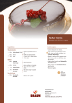
1
Sacher Lasertechnik Group
TEC070 TEC072 DBR Butterfly Laser Mount
User Manual
http://www.sacher-laser.com
Sacher LasertechnikGroup
Warranty
This Sacher LasertechnikGroup product is warranted against defects in
materials and workmanship for a period of two years from date of
shipment.
Duration and conditions of warranty for this product may be superceded
when the product is integrated into (becomes a part of) other Sacher
Sacher LasertechnikGroup products. During the warranty period, Sacher
LasertechnikGroup will, at its option, either repair or replace products
which prove to be defective.
The warranty period begins on the date of delivery or on the date of
installation if installed by Sacher LasertechnikGroup.
This warranty is in lieu of all other guarantees expressed or implied and
does not cover incidental or consequential loss.
Copyright 2006, Sacher LasertechnikGroup. All rights reserved.
Service
Information and advice about the performance or operation of Sacher
LasertechnikGroup products is available from our web site and our
applications engineers.
For quickest response ask for ‘Technical Support’ and have your model
and serial number available. Support is available by:
Sacher LasertechnikGroup
Rudolf-Breitscheid-Str. 1–5
35037 Marburg, Germany
Tel: +49 6421 305 – 0, Fax: +49 6421 305 - 299
[email protected]
or
5765 Equador Way
Buena Park, CA 90620
USA
Tel.: +1 800 352 3639, Fax: +1 714 670 7662
User Manual Laser Mount TEC070 TEC072
Part Number:
Printed: Jun-06 Preliminary
Sacher LasertechnikGroup
Content
General Information
1
General Description .................................................... 1
Opto-Mechanical Construction ................................... 2
Mounting 14-Pin Butterfly Devices............................ 3
Safety an Proper Handling .......................................... 4
Label Identification ..................................................... 6
DBR Laserdiode Driver Setup .................................... 7
Remote Interlock Connector /Indicator Lamp ............ 7
Butterfly Pin Layout TEC070 and TEC072................ 8
Product Options .......................................................... 8
Dip Swiches ................................................................ 9
Connectors ................................................................ 10
Specifications
11
Laser Spec ................................................................. 11
TEC Spec .................................................................. 11
Mechanical Drawings ............................................... 12
Laser Mount Schematic TEC070.............................. 14
Laser Mount Schematic TEC072.............................. 15
Technical Support ..................................................... 16
User Manual Laser Mount TEC070 TEC072
Part Number:
Printed: Jun-06 Preliminary
Sacher LasertechnikGroup
General Information
General Description
The laser head contains all necessary parts for a safely operation of a
DBR diode laser within a 14pin butterfly package. The following
description gives an overview as well as detailed information about the
following topics:
• the opto-mechanical construction
• 14-pin butterfly connection
• the electrical connectors
• features of the protection circuitry
• the bias-T circuit.
• safety switch
• indicator lamp
User Manual Laser Mount TEC070 TEC072
1
Sacher LasertechnikGroup
Opto-Mechanical Construction
The laser head is a professional mount for butterfly style laser modules
and offers several advantages over home built solutions. It offers
unlimited access to all the relevant operating conditions. Especially the
use of the DBR and phase segments has been prepared.
The laser module will be screwed into the mount with 4 metric screws
of type M2x6. When screwed into place the laser module is in thermally
well conducting contact to a heat sink formed by the chassis of the
mount.
On the laser head are two Sub-D connectors for the temperature control
and current control cable provided. Furthermore there are three SMA
high frequency connector for modulating the different segments of the
DBR. The jack connector has been implemented for cases where the
operator wants or has to provide increased laser security using a remote
interlock. When unused the jack connector may be short circuited with
a M2,5x12 screw as delivered. The connector may also be used to
connect a remote interlock switch that opens the interlock circuit in case
of an unwanted condition (like door opened etc.).
GAIN
DBR
PHASE
Zero
insertion
force (ZIF)
Socket
Remote
Interlock
connector
Figure 1: Rear view of the laser head
DBR
Dip switches for
changing the
operation conditions
Proper mounting of the laser head is essential for stable wavelength
operation. The wavelength is strongly dependent on the temperature of
the DBR laser, which is actively stabilized using the thermoelectric
cooler.
The cooler utilizes the laser head housing as heat reservoir. For this
reason, the butterfly mount needs to provide a good thermal path away
from the laser. The laser mount features ZIF sockets that provide also
best thermal contact.
After mounting the laser head, take precautions to prevent back
reflections into the laser aperture.
Prevent back reflections into the laser head. Optical feedback may
damage the laser diode.
Isolation can be achieved by angling the used optics or with the use of
an optical isolator. The degree of isolation required depends on how
you are using the laser. Please contact Sacher Lasertechnik for technical
support with your application.
User Manual Laser Mount TEC070 TEC072
2
Sacher LasertechnikGroup
Mounting 14-Pin Butterfly Devices
This device should not be operated unless properly attached to a heat
sink. Failure to adequately cool the device will cause immediate and
permanent damage. The heat sink should be made of copper, aluminium
or another material with similar, or better, thermal conductivity. The
heat sink surface finish should be 0.8µm (32 µ-in) or better. The surface
flatness under the package should be better than 12µm (0.0005"). The
heat sink must be capable of removing heat from the package in order
that the case temperature of the package does not exceed its specified
maximum operating temperature. The case temperature limits for all
butterfly packages are specified as the maximum temperature on the
base of the package. Use of a thermal interface material between the
package and heat sink is strongly recommended. A good quality thermal
grease or thermal interface pad can be used. Typically, is desirable to
achieve less than 0.2 K/W between the package and the heat sink; this
can be achieved if the thermal interface material is rated at 2.5 x 10⁻⁵
Km2/W (0.038 Kin2/W) or better. We recommends Panasonic “PGS”
(Pyrolytic Graphite Sheet) thermal interface material. The package can
be mounted with M2.5x 0.45 screws. First, the screws must be tightened
to a torque of 0.015 Nm (2.0 inoz) in the order, 1-3-2-4, see Figure 2:
Screw numbers on mounted package. Next, the screws should be
tightened to 10 in-oz (0.070N-m) in the same order, 1-3-2-4.
Figure 2: Screw numbers on mounted package
The package can be permanently distorted and the internal components
destroyed if the screws are tightened unevenly or are over tightened.
The screw threads should be locked to prevent loosening over the time.
Making the Safety Interlock Connections:
User Manual Laser Mount TEC070 TEC072
3
Sacher LasertechnikGroup
Safety an Proper Handling
The user of the laser mount is primary responsible for being
compliant with the laser safety requirements.
We recommend to pay attention on the following topics.
Laser Safety
Classification requirements and user guideline described in DIN EN 60
825-1:2001 should be fulfilled.
Laser products for introduction into commerce in or imported into the
United States must
• Comply with 21 CFR §1040.10 and §1040.11(medical laser
products) as applicable,
• be certified and identified in accordance with 21 CFR §1010.2
and, §1010.3
• Be reported in accordance with 21 CFR §1002.10
The connector between controller and laser module is not suited for
connection or disconnection while operation.
Proper Handling
The storage temperature of the laser head is -20 °C (-4 °F) to
75 °C (167 °F). Protect the laser system from condensing if transferred
from a cold environment into a warmer working environment. Never
operate the laser head or a grating in an environment that is above
-10 °C (14 °F) or below 65 °C (149 °F). Never place the laser head on a
heat source such as a power supply. This may result in distortion of the
wavefront leading to an unstable multimode operation. Always wear a
grounding wrist strap when operating ta laser. Diode lasers are
extremely susceptible to damage from static discharge. The optical
components of the system should never need to be cleaned under
normal operating conditions with the cover closed. Do not attempt to
clean the optics yourself. Doing so will void the warranty. If the optics
become accidentally soiled send the unit back to the manufacturer for
cleaning.
User Manual Laser Mount TEC070 TEC072
4
Sacher LasertechnikGroup
Fiber Handling Precautions
This device could be equipped with a fiber optic pigtail, and should
only be handed by qualified operators with specific training on handling
fibered devices. The minimum bend radius for the fiber on this device
must be respected. Bending the fiber to a smaller radius than the
minimum may result in immediate breakage of the fiber or it may
induce damage, which is not immediately apparent but will lead to
premature device failure. Always wear eye protection when handling
optical fiber.
Handling Precautions for ESD
Follow all of the following precautions when handling a pigtailed
product, as this device may be damaged by static electrical discharge.
Remove any lead shorting clips only when ready to use. Replace the
clips for device storage or transport. Always store and transport in
closed conductive containers. Remove from containers only after
grounding at a Static Control Work Station. Personnel who handle this
device should wear a static dissipative outer garment and should be
grounded at all times. Floors should have a grounded static dissipative
covering or treatment. Tables should have a grounded static dissipative
covering. Avoid insulating materials of any kind. Always use a
grounded soldering iron to install. Test only at static controlled
workstations. Failure to follow all of these precautions may result in
immediate failure of the device or shortened life.
User Manual Laser Mount TEC070 TEC072
5
Sacher LasertechnikGroup
Label Identification
You find the following labels on the laser mount.
Figure 3: Top and bottom labels
This label shows the logo of Sacher LasertechnikGroup, located on
top of the housing.
Identification label with Sacher part number and serial number
User Manual Laser Mount TEC070 TEC072
6
Sacher LasertechnikGroup
DBR Laserdiode Driver Setup
The following schematic shows a typical setup for diode laser
applications.
Figure 4: Typical DBR laser setup
The laser diode controller consist of
• a low noise current source witch is used to drive the BBR Gain
(TEC070) or the DBR segment(TEC072) of the DBR diode
• a control unit witch supervised the interlock, the safety relay
and the indicator lamp
• a temperature controller witch is able to read out the DBR temp
sensor and control the peltier cooler
• a modulation unit witch is used to drive the internal heating
resistors of the DBR diode
Remote Interlock Connector /Indicator Lamp
The TEC70, TEC72 are equipped with a remote interlock connector
located on the side panel and an indicator lamp on top.
In order to enable the laser driver, a short circuit must be applied across
the terminals of the Remote interlock connector. In practice this
connection is made available to allow the user to connect a remote
actuated switch to the connector (i.e. an open door indicator). The
switch (which must be normally open) has to be closed in order for the
unit to be enabled. Once the switch is in an open state the laser diode
must automatically shutdown.
This safety functionality is
Sacher Laser diode controller.
See chapter before.
User Manual Laser Mount TEC070 TEC072
available
together
with
the
7
Sacher LasertechnikGroup
All units are configured with a shorting device installed in the interlock
connector. If you are not going to use this feature then you can leave the
shorting device installed and the unit will operate normally as described
in the procedures in this manual. If you wish to make use of the
interlock feature you will need to acquire the appropriate connector
mate and wire it your remote interlock switch. Next, remove the
shorting device by unscrewing it from the input and install the
connector into the Interlock input.
The interlock input only accepts a 2.5mm mono phono jack.
Butterfly Pin Layout TEC070 and TEC072
The following table describe the butterfly laser socket connection.
This connection table must match with the laser diode datasheet.
Pin-No
1
2
3
4
5
6
7
Description
Peltier (+)
Thermistor
PD Anode
PD Cathode
Thermistor
DBR Anode
DBR Anode
Pin-No
14
13
12
11
10
9
8
Description
Peltier (-)
Case Ground
N/C
LD Cathode (-)
LD Anode (+)
Phase Anode
Phase Anode
Table 1: Connection table of the butterfly
30.00
26.00
1
8
14
8.90
12.70
2.5
7
2.54
17.78
Figure 5: Pin connection of the butterfly
Product Options
The following product options are available.
Name
Description
Laser Mount TEC070 Laser Mount for butterfly housing
DBR Laser Diodes GAIN segment driven
Laser Mount TEC072 Laser Mount for butterfly housing
DBR Laser Diodes DBR segment driven
User Manual Laser Mount TEC070 TEC072
Sacher Part Number
23-4000-43-0008
23-4000-43-0013
8
Sacher LasertechnikGroup
Dip Swiches
The TEC71 is equipped with 3 DIP switches to support different
polarity and case ground settings .In case of a DBR laser different
modulation settings are possible.
S2
S1.1
S1.2
S1.3
S2.1
S2.2
S3.1
S3.2
S1
S3
Connect electronic ground to laser cathode
Connect test pad laser to cathode
Connect Butterfly case to laser cathode
Connect Gain segment to Phase Segment
Connect DBR segment to Phase Segment
Connect Gain segment to DBR
Not used
User Manual Laser Mount TEC070 TEC072
9
Sacher LasertechnikGroup
Connectors
Laser Input
Standard Sub-D9 FEMALE connection rated for 5A.
This connection is required.
Pin Nr.
1
2
3
4
5
6
7
8
9
Signal Name
Interlock
PDLD GND
PD+
Interlock
REL+
LDLD+
GND
Description
Photodiode Signal Minus
Laser Diode Ground
Photodiode Signal Plus
Safety Relay Plus
Laser Diode Plus
TEC Input
Standard Sub-D9 MALE connection rated for 5A. This connection is
usually required, but optional if temperature control is not needed.
Pin Nr.
1
Signal Name
MGND
Description
4
5
6
7
8
9
NTC
TEC-GND
TEC-OUT
NTC
Temperature Sensor
Peltier Output
Temperature Sensor
MOD INPUTS
The input is used for modulating the laser a non differential input.
Pin Nr.
1
2
Signal Name
MOD P
MOD M
User Manual Laser Mount TEC070 TEC072
Description
Modulation Plus
Modulation Minus
10
Sacher LasertechnikGroup
Specifications
Laser Spec
Laser
Max Laser Current :
Laser Polarity TEC070:
Laser Polarity TEC071:
Laser Polarity TEC072:
2A (Limit of LD)
negative
negative
positive
RF Modulation Inputs
Input Impedance :
Coupling Capacitor :
Max Input Voltage:
Coupling Connector :
Freq-Range :
47Ohm
10uF
25V
SMA
100kHz..100MHz
Safety Relais
Relay coil :
12V/320R
TEC
Max Current:
Cooling Capacity:
Temperature Range:
Temp Sensors:
5.0A
Laser Specific
LD dependent
Laser Specific
TEC Spec
User Manual Laser Mount TEC070 TEC072
11
Sacher LasertechnikGroup
Mechanical Drawings
Laser Mount TEC070 TEC072
Laser head:
Size (H x W x L):
Weight:
25.5 x 94 x 106.7 mm
1.0 x 3.7 x 4.2 inch
330g
Figure 6: Top view of the TEC070 TEC072 laser head.
a)
b)
Figure 7: Side view of the TEC070 TEC072 laser head. a: right side; b: left
side
User Manual Laser Mount TEC070 TEC072
12
Sacher LasertechnikGroup
Figure 8: Rear view of the CHEETAH laser head.
Figure 9: Bottom view of the TEC070 TEC072 laser head.
User Manual Laser Mount TEC070 TEC072
13
Sacher LasertechnikGroup
Laser Mount Schematic TEC070
User Manual Laser Mount TEC070 TEC072
14
Sacher LasertechnikGroup
Laser Mount Schematic TEC072
User Manual Laser Mount TEC070 TEC072
15
Sacher LasertechnikGroup
Technical Support
Information and advice about the performance or operation of your
laser is available from our application engineers. For quickest response
ask for “Technical Support” and have your model and serial number
available. Support is available by:
Sacher – LasertechnikGroup
Rudolf-Breitscheid-Str. 1–5
35037 Marburg, Germany
Tel: +49 6421 305 – 290, Fax: +49 6421 305 - 299
[email protected]
or
5765 Equador Way
Buena Park, CA 90620
USA
Tel.: +1 800 352 3639, Fax: +1 714 670 7662
User Manual Laser Mount TEC070 TEC072
16