1
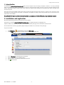
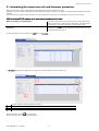
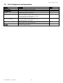
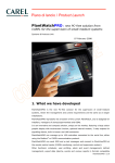
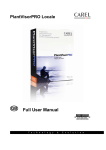
Floating Suction Pressure Control
User manual
PlantVisorPRO
CONTENTS
1.
2.
3.
4.
5.
6.
7.
8.
9.
10.
Introduction ................................................................................................................................................................................................... 3
Installation and registration ......................................................................................................................................................................... 3
How to use Floating Suction Pressure Control .......................................................................................................................................... 4
Navigating the pages .................................................................................................................................................................................... 4
Opening Floating Suction Pressure Control ............................................................................................................................................... 5
Configuring Floating Suction Pressure Control.......................................................................................................................................... 5
Starting Floating Suction Pressure Control................................................................................................................................................. 7
Checking the status of the systems............................................................................................................................................................. 8
Customising the compressor rack and showcase parameters ................................................................................................................. 9
List of compressor rack parameters .......................................................................................................................................................... 10
Floating Suction Pressure Control
1. Introduction
The PlantVisorPRO Floating Suction Pressure Control plug-in has been designed to reduce the energy consumption of showcases. To do this, it periodically
analyses the operation of the showcases associated with the compressor racks that have been enabled, and, based on the duty cycle values calculated for each
showcase, automatically modify the set point of the rack. This minimises the delivery of liquid refrigerant and consequently reduces power consumption in the
medium and long term.
Of the devices present in the installation, Floating Suction Pressure Control only involves those that manage showcases or compressor racks, and for these devices
only displays the essential parameters for this function. The parameters of the algorithm are already set in the factory, however they can be customised based on
specific features of the installation.
Note: A PlantVisorPRO plug-in is an optional module to be installed on a computer where PlantVisorPRO Local is already installed and configured.
2. Installation and registration
After having installed Floating Suction Pressure Control it needs to be registered.
At www.carel.com click the link Request PlantVisorPRO activation code, and complete all the fields on the application form.
Important: the MAC-address will be requested, which is found on the PlantVisorPRO system page, and the “Serial Number” printed on the CD.
Once the data have been confirmed, a page will be displayed showing the “activation code”, to be entered on the system page.
Then, proceed as follows:
1.
2.
Click Configuration
in PlantVisorPRO Local and select System pages
Click the Plugin page: the following page will be displayed for entering the registration data:
1.
2.
3.
4.
From the Description list select the plug-in to be registered.
Enter the serial number on the installation package.
Enter the activation code previously acquired from www.carel.com.
Click
to save the data.
Code +030220508 - rel. 1.1 23/05/08
3
Floating Suction Pressure Control
3. How to use Floating Suction Pressure Control
The control function must be first configured and then activated. To do this, proceed as follows:
1.
2.
3.
4.
5.
Open the plug-in.
Choose which systems the control is to act on.
Associate these systems with the showcases.
Start Floating Suction Pressure Control.
Monitor variations in the set point of the compressor rack in order to adjust, if necessary, the parameters of the algorithm.
Once the control has started, the following operations are possible:
•
Enable/disable the control on a compressor rack
•
Reset the minimum and maximum peaks of the duty cycle on all the showcases
•
Reset the minimum and maximum peaks of the duty cycle on an individual showcase
•
Modify the parameters of the compressor rack and the maximum duty cycle of each showcase
4. Navigating the pages
The control has a first level with three pages: Main, Associations and Systems. These pages are connected by the Next button and are used to configure the
Floating Suction Pressure Control. They can also be opened directly at any time by clicking the name of the page.
Here is the typical procedure for configuring the control:
Main
Click …
Configure
Systems
Click
Next
Associations
Click
Next
The second level accesses two pages, Compressor rack detail and Parameters, which are used to display and set the parameters for the compressor rack and
the maximum duty cycle for the showcase. Click the name of the page to open it.
To display the details of a compressor rack:
Main
Code +030220508 - rel. 1.1 23/05/08
Double
click
the graph
relating to
the rack
Compressor rack detail
Click …
the
Parameters
page
4
Parameters
Next
Floating Suction Pressure Control
5. Opening Floating Suction Pressure Control
To access the plug-in click
and select PLUG-IN: the list of plug-ins installed will be shown:
6. Configuring Floating Suction Pressure Control
After having entered the PLUG-IN section, double click Floating Suction Pressure Control: the main page is shown for configuring the control:
Code +030220508 - rel. 1.1 23/05/08
5
Floating Suction Pressure Control
Click Configuration: the Systems page is shown, with the list of compressor rack controllers compatible with Floating Suction Pressure Control. On this page, select
the systems to be enabled in the plugin.
NOTE: any devices not compatible with Floating Suction Pressure Control are not shown in the list.
NOTE: a maximum of eight systems can be enabled.
Click Enable for all the systems to be enabled.
At the end click Next: the page is displayed for associating the showcases with the enabled systems:
NOTE: any controllers not compatible with Floating Suction Pressure Control are not shown in the list.
The page shows all the devices that can be used to control showcases.
Only associate the devices that are effectively connected to the showcases with the systems. Leave as not configured (“--------“) any devices that are not connected to
the showcases in the list.
Code +030220508 - rel. 1.1 23/05/08
6
Floating Suction Pressure Control
Click Next: the configuration is saved and the main page is shown again, with the graphs already set out for each rack:
The plug-in is ready to be started and control the cooling cycle of the showcases based on the default parameters already set.
7. Starting Floating Suction Pressure Control
From the main page of the plug-in, click
1
2
3
Current set point
Minimum set point
Maximum set point
Code +030220508 - rel. 1.1 23/05/08
: Floating Suction Pressure Control is started and the first calculation is made of the duty cycle of each showcase.
Current value of the Set Point variable on the compressor rack
Minimum value available for the Set Point variable on the compressor rack
Maximum value available for the Set Point variable on the compressor rack
7
Floating Suction Pressure Control
8. Checking the status of the systems
After having started the control, the trend of the set point on each compressor rack can be checked by reading the graph on the main page.
If all the showcases associated with the compressor rack have a duty cycle lower than the maximum set point defined for the showcase, Floating Suction
Pressure Control will increase the value of the set point on the compressor rack.
If, on the other hand,, at least one showcase has a duty cycle above the maximum duty cycle set, Floating Suction Pressure Control will decrease the value of
the set point on the compressor rack.
To see which showcase is making the request, double click the compressor rack to see the details.
Compare the page with the list of parameters used by Floating Suction Pressure Control and the duty cycle values for each showcase:
NOTE: for the description of the compressor rack parameters, see List of compressor rack parameters.
Variable
Set DC
Current DC
Min DC recorded
Max DC recorded
RST
RESET
Description
Maximum value of the duty cycle set on the Parameters page
Last calculated duty cycle value
Minimum duty cycle value recorded
Maximum duty cycle value recorded
Resets the minimum and maximum values saved
Resets the minimum and maximum values saved for all the showcases associated with the rack
For example if the current DC exceeds the set DC, it means that the showcase is struggling to reach the operating temperature, and must be checked.
Press RST to set the minimum and maximum duty cycle values of a showcase to zero, for example the maximum duty cycle set has been changed (see When
to modify the maximum duty cycle of a showcase).
Press RESET to set the minimum and maximum duty cycle values of all the showcases to zero, for example the compressor rack parameters have been
modified (see When to modify the rack parameters).
Code +030220508 - rel. 1.1 23/05/08
8
Floating Suction Pressure Control
9. Customising the compressor rack and showcase parameters
Floating Suction Pressure Control is supplied with standard parameters that manage the operation of the control.
Nonetheless, some of the compressor rack parameters or the maximum duty cycle of a showcase can be changed, for example to adjust the algorithm to the specific
installation.
The custom parameters are always saved in the database, even after disabling the compressor rack (see Configuring Floating Suction Pressure Control).
NOTE: after having modified the compressor rack or showcase parameters, always re-start the control.
When to modify the rack parameters
When to modify the maximum duty cycle of a
showcase
For example, if the installation has a lot of showcases, to increase the maximum
number of showcases for a failed connection. Alternatively, if the installation has
network problems, the maximum offline time may need to be increased.
If when checking the Detail page all the values saved for the duty cycle are above to
the maximum duty cycle set, check the operation of the showcase and if necessary
increase the maximum duty cycle set.
To modify the parameters, on the compressor rack Detail page, click Parameters:
The Parameters page will show the parameters of the compressor rack and the maximum duty cycle that can be set:
1
2
3
4
Select the compressor rack whose parameters are being set.
Compressor rack parameters used by the control.
Maximum duty cycle to be set on all the showcases for the compressor rack and button to save the data.
Maximum duty cycle to be set on the individual showcase for the compressor rack in question.
to save the changes.
Modify the parameters and click
Stop and restart the control to make the changes effective.
Code +030220508 - rel. 1.1 23/05/08
9
Floating Suction Pressure Control
10.
List of compressor rack parameters
Parameter
Current set point
Minimum set point
Maximum set point
Gradient
Time window for the DC calculation
DC calculation frequency
Maximum failed connection time
Maximum number of showcases not
connected
Code +030220508 - rel. 1.1 23/05/08
Description
Current value of the Set Point variable on the rack
Minimum value available for the Set Point variable.
Maximum value available for the Set Point variable.
Establishes how much the set point will be increased and decreased by following the
calculation of the duty cycle on the showcases
Indicates how long the data corresponding to the solenoid on each individual showcase is
saved in the memory. The duty cycle will be calculated based on these data; once the
window is full each new value will overwrite the oldest value.
The value may vary from 10 to 180 minutes.
Indicates how often the duty cycle must be calculated for the showcases associated with the
rack, and consequently the set point changed if necessary.
The value may vary from 10 to 180 minutes.
Maximum percentage of failed acquisitions for each showcase associated with the rack. If
this is exceeded, the showcase is considered offline.
If when the duty cycle is calculated the showcases that are offline exceed this number, the
set point is not changed on the rack.
10
Default
120 minutes
30 minutes
30%
3
CAREL S.p.A.
Via dell’Industria, 11 - 35020 Brugine - Padova (Italy)
Tel. (+39) 049.9716611 Fax (+39) 049.9716600
http://www.carel.com - e-mail: [email protected]
Code: +030220508 rel. 1.1 23/05/2008
Agenzia / Agency: