1
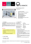
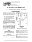
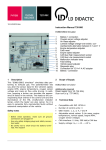
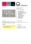
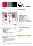
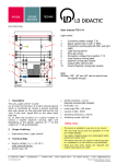
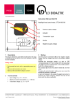
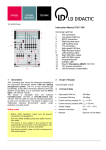
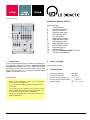
10/14-W2010-Wei Instruction Manual 738 113 1 6 2 7 3 4 5 12 8 9 10 11 13 1 14 15 Description This "Cornering light" serves the classroom retrofitting of the automotive educational system CAN bus lighting management system, 738 111, to add cornering light functionality. It also offers connection options for two LED daytime running lights, e.g. in connection with the Headlights, 738 166 and 738 167. Safety notes - Before initial operation, make sure all ground connections are plugged in! - Use only safety bridging plugs and safety connection leads! - The device is only usable in the context of the experimental environment in this description. Use in an actual vehicle is strictly prohibited! - The device explicitly does not fully correspond to ECE specifications. Cornering Light 1 T30 connection 2 Low-speed CAN bus 3 SDVC connection 4 Right fog lamp input 5 Left fog lamp input 6 T15 connection 7 High-speed CAN bus 8 Right fog lamp output 9 Left fog lamp output 10 Right LED DRL output 11 Left LED DRL output 12 Programming key 13 Indicator LED 14 Plug for Simulation ABS/Ti, 579 163 15 T31 ground connection 2 Scope of Supply Cornering light module 3 Technical Data High-speed CAN bus 500 kBps Low-speed CAN bus 100 kBps Current carrying capacity FL Imax = 4.5 A Current carrying capacity DRL Imax = 150 mA Supply voltage UB = +12 – +15 V= Instruction Manual 4 4.1 Page 2/3 Startup is readable by the Instrument cluster unit, 739 6021, as a CAN bus communication. If both signals are available in parallel, the CAN bus signal takes precedence. Setup 1. Connect the device to the Intelligent lighting management system, 738 111. 2. Link the connections for T30 (1), T15 (6), ground (15), low-speed CAN bus (2) and high-speed CAN bus (7). 3. Link the outputs for the Electrical system control unit, 738 111-01, for the fog lamps 55L and 55R with the inputs 55L (4) and 55R (5) on the adaptive headlight module. 4. Connect the Auxiliary headlamps, 738 18, to the adaptive headlight module's outputs 55L (9) and 55R (8). 5. If available: Connect the DRL in Headlights, 738 166 and 738 167, to the DRL outputs (10 & 11). 6. If no Instrument cluster unit, 739 6021 is available: Plug the speed simulator Simulation ABS/Ti, 579 163, into Slot 14 and link its output with input "V" (3). 7. For a clear display of the speed, you may use the Tachometer/speedometer digital, 739 6023. 4.2 Functional Test The system requires 12 VDC for operation. Switch the ignition (T15) on and then the cornering light (T56b). Activate the left or right turn signal: the respective fog lamp must light up. 4.3 4.4 Programming Reprogramming the cornering light module is possible without a PC. To initiate the programming mode, press and hold the "T" button (12) for approx. 2 seconds until the "MODE" LED (13) blinks green. You can then press the "T" button again once or several times within the next second to select the programming function: Module off Module on Speed threshold Persistence Steering angle sensor calibration DRL function If after the programming mode's initiation, you do not press the button again, the system automatically leaves this mode within 3 seconds. After the function's selection and programming, the adaptive headlight module confirms the adoption of the new values by illuminating the left and right fog lamps. Operation If the ignition and the light are on, and the programming mode has not deactivated the adaptive headlight module, a fog lamp turns on if: at a standstill, the turn signal is on, or at v<vmax, a steering wheel angle >90° is detected. To calibrate the steering wheel angle to 0°, carry out programming "5." After passing the speed threshold, the fog lamp turns back off after the set persistence. In the case of errors "Ground interruption," "Power supply interruption" and "T15 interruption," the "MODE" LED blinks red! Note: The speed signal: can connect directly to input "V" (3) with 1 Hz ≙ 1 km/h as a PWM signal, or LD DIDACTIC GMBH Leyboldstrasse 1 D-50354 Huerth / Germany Phone +49 (0)2233 604-0 Fax +49 (0)2233 604-222 e-mail: [email protected] by LD Didactic GmbH Printed in the Federal Republic of Germany Technical alterations reserved Page 3/3 In the programming mode, press the button only as often as listed below to reprogram the corresponding function, and wait until the auxiliary headlamps finally confirm the adoption of the new values by illuminating alternately. Only then can you change another parameter, as necessary. Instruction Manual briefly, and this automatically sets a value of 1 second; hold it longer than 10 seconds, and this programs a value of 10 seconds. Press once: The adaptive headlight module is activated. Press twice: The adaptive headlight module is deactivated. Press 3 times: You can now change the speed at which the fog lamp turns back off after going around a corner (per ECE 119 at 40 km/h). Default: 20 km/h Setting range: 20 – 60 km/h Set the desired speed on the vehicle. Then start the programming, and the new value is then stored as the set speed. Press 4 times: You can now set the persistence. Default: 4s Setting range: 1 – 10 s This defines the new length of time the button remains pressed at the fourth pressure. Press it only Press 5 times: This serves to determine the steering wheel's "straight forward" position. The "MODE" LED lights up orange until you bring the steering angle sensor to the center position (straight ahead, 0°). Note: The values above are not permanently stored! Press 6 times: You can now set the behavior of the DRL when the cornering light turns on. Behavior according to ECE R87: the DRL switches off if the cornering light is on Behavior according to ECE R7: the DRL dims if the cornering light is on The sixth pressure on the button toggles between the two behaviors. Note: This setting is permanently stored!