1
Debugging Package for
Motorola 68K CISC CPUs
User's Manual
(Part 2 of 2)
68KBUG2/D3
Notice
While reasonable efforts have been made to assure the accuracy of this document,
Motorola, Inc. assumes no liability resulting from any omissions in this document,
or from the use of the information obtained therein. Motorola reserves the right to
revise this document and to make changes from time to time in the content hereof
without obligation of Motorola to notify any person of such revision or changes.
No part of this material may be reproduced or copied in any tangible medium, or
stored in a retrieval system, or transmitted in any form, or by any means, radio,
electronic, mechanical, photocopying, recording or facsimile, or otherwise,
without the prior written permission of Motorola, Inc.
It is possible that this publication may contain reference to, or information about
Motorola products (machines and programs), programming, or services that are
not announced in your country. Such references or information must not be
construed to mean that Motorola intends to announce such Motorola products,
programming, or services in your country.
Restricted Rights Legend
If the documentation contained herein is supplied, directly or indirectly, to the U.S.
Government, the following notice shall apply unless otherwise agreed to in
writing by Motorola, Inc.
Use, duplication, or disclosure by the Government is subject to restrictions as set
forth in subparagraph (c)(1)(ii) of the Rights in Technical Data and Computer
Software clause at DFARS 252.227-7013.
Motorola, Inc.
Computer Group
2900 South Diablo Way
Tempe, Arizona 85282
Preface
The Debugging Package for Motorola 68K CISC CPUs User's Manual provides general
information for the onboard Þrmware package for all Motorola 68000 CISC CPU
and MPU VMEmodule boards.
This document is bound in two parts. Part 1 (68KBUG1/D3) contains the Table of
Contents and Chapters 1 through 3. Part 2 (68KBUG2/D3, this volume) contains
Chapters 4 and 5, Appendices A through I, and the Index.
This manual is intended for anyone who wants to design OEM systems, supply
additional capability to an existing compatible system, or work in a lab
environment for experimental purposes.
The following Þrmware packages and boards are covered in this manual:
MVME162
MVME172
MVME166
MVME167
MVME176
MVME177
162Bug
172Bug
166Bug
167Bug
176Bug
177Bug
The Þrmware packages are referred to as 16XBug in this manual. The boards are
referred to as MVME16X.
This manual describes the debugger, the debugger command set, the one-line
assembler/disassembler, and system calls. These functional elements are common
to all Þrmware packages.
Installation, start-up, diagnostics tests, and environmental parameters are
described in the diagnostic manuals for each of the Þrmware packages.
A basic knowledge of computers and digital logic is assumed.
Motorola and the Motorola symbol are registered trademarks of Motorola, Inc.
SYSTEM V/68 is a trademark of Motorola, Inc.
Timekeeper and Zeropower are trademarks of SGS-THOMSON Microelectronics.
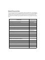
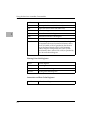
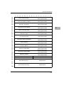
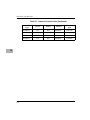
Related Documentation
The following publications are applicable to Motorola 68K CISC CPU debugging
packages and may provide additional helpful information. If not shipped with this
product, they may be purchased by contacting your local Motorola sales ofÞce.
Non-Motorola documents may be obtained from the sources listed following the
table.
Document Title
Motorola
Publication Number
M68040 Microprocessors User's Manual
M68040UM/AD
M68060 Microprocessors User's Manual
M68060UM/AD
MVME050 System Controller Module User's Manual
MVME050/D
MVME162 ProgrammerÕs Reference Guide
MVME162PG/D
MVME162FX ProgrammerÕs Reference Guide
MVME162LXPG/D
MVME162LX ProgrammerÕs Reference Guide
V162FXA/PG
MVME172 ProgrammerÕs Reference Guide
VME172A/PG
Single Board Computers Programmer's Reference Guide
VMESBCA1/PG and
VMESBCA2/PG
162Bug Diagnostics UserÕs Manual
V162DIAA/UM
167Bug Debugging Package UserÕs Manual
MVME167BUG/D
172Bug Diagnostics UserÕs Manual
V172DIAA/UM
177Bug Diagnostics User's Manual
V177DIAA/UM
MVME320B VMEbus Disk Controller Module User's Manual
MVME320B/D
MVME323 ESDI Disk Controller User's Manual
MVME323/D
MVME327A VMEbus to SCSI Bus Adapter and
MVME717 Transition Module User's Manual
MVME327A/D
MVME327A Firmware User's Manual
MVME327AFW/D
MVME328 VMEbus Dual SCSI Host Adapter User's Manual
MVME328/D
MVME335 Serial and Parallel I/O Module User's Manual
MVME335/D
MVME350 Streaming Tape Controller VMEmodule User's Manual
MVME350/D
MVME350 IPC Firmware User's Guide
MVME350FW/D
MVME374 Multi-Protocol Ethernet Interface Module User's Manual MVME374/D
MVME376 Ethernet Communication Controller User's Manual
MVME376/D
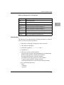
Note
Although not shown in the above list, each Motorola
Computer Group manual publication number is
suffixed with the revision level of the document, such
as Ò2Ó (the second revision of a manual); a supplement
bears the same number as a manual but has a suffix
such as "2A1" (the first supplement to the second
revision of the manual).
The following publications are available from the sources indicated.
ANSI Small Computer System Interface-2 (SCSI-2), Draft Document X3.131-198X,
Revision 10c; Global Engineering Documents, P.O. Box 19539, Irvine, CA 92714.
Versatile Backplane Bus: VMEbus, ANSI/IEEE Std. 1014-1987, The Institute of
Electrical and Electronics Engineers, Inc., 345 East 47th Street, New York, NY 10017
(VMEbus SpeciÞcation). This is also available as Microprocessor system bus for 1 to 4
byte data, IEC 821 BUS, Bureau Central de la Commission Electrotechnique
Internationale; 3, rue de VarembŽ, Geneva, Switzerland.
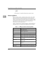
Manual Terminology
Throughout this manual, a convention has been maintained whereby data and
address parameters are preceded by a character which speciÞes the numeric
format as follows:
$
hexadecimal character
%
binary number
&
decimal number
Unless otherwise speciÞed, all address references are in hexadecimal throughout
this manual.
An asterisk (*) following the signal name for signals which are level signiÞcant
denotes that the signal is true or valid when the signal is low.
An asterisk (*) following the signal name for signals which are edge signiÞcant
denotes that the actions initiated by that signal occur on high to low transition.
In this manual, assertion and negation are used to specify forcing a signal to a
particular state. In particular, assertion and assert refer to a signal that is active or
true; negation and negate indicate a signal that is inactive or false. These terms are
used independently of the voltage level (high or low) that they represent.
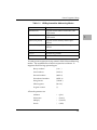
Data and address sizes are deÞned as follows:
❏
A byte is eight bits, numbered 0 through 7, with bit 0 being the
least significant.
❏
A word is 16 bits, numbered 0 through 15, with bit 0 being the
least significant.
❏
A longword is 32 bits, numbered 0 through 31, with bit 0 being
the least significant.
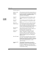
Conventions
The following conventions are used in this document:
bold
is used for user input that you type just as it appears. Bold is also used
for commands, options and arguments to commands, and names of
programs, directories, and files.
italic
is used for names of variables to which you assign values. Italic is also
used for comments in screen displays and examples.
courier
is used for system output (e.g., screen displays, reports), examples, and
system prompts.
<RETURN> or <CR>
represents the carriage return or Enter key.
CTRL or ^
represents the Control key. Execute control characters by pressing the
CTRL key and the letter simultaneously, e.g., CTRL-d.
Safety Summary
Safety Depends On You
The following general safety precautions must be observed during all phases of operation, service, and
repair of this equipment. Failure to comply with these precautions or with speciÞc warnings elsewhere in
this manual violates safety standards of design, manufacture, and intended use of the equipment.
Motorola, Inc. assumes no liability for the customer's failure to comply with these requirements.
The safety precautions listed below represent warnings of certain dangers of which Motorola is aware. You,
as the user of the product, should follow these warnings and all other safety precautions necessary for the
safe operation of the equipment in your operating environment.
Ground the Instrument.
To minimize shock hazard, the equipment chassis and enclosure must be connected to an electrical ground.
The equipment is supplied with a three-conductor ac power cable. The power cable must be plugged into
an approved three-contact electrical outlet. The power jack and mating plug of the power cable meet
International Electrotechnical Commission (IEC) safety standards.
Do Not Operate in an Explosive Atmosphere.
Do not operate the equipment in the presence of ßammable gases or fumes. Operation of any electrical
equipment in such an environment constitutes a deÞnite safety hazard.
Keep Away From Live Circuits.
Operating personnel must not remove equipment covers. Only Factory Authorized Service Personnel or
other qualiÞed maintenance personnel may remove equipment covers for internal subassembly or
component replacement or any internal adjustment. Do not replace components with power cable
connected. Under certain conditions, dangerous voltages may exist even with the power cable removed. To
avoid injuries, always disconnect power and discharge circuits before touching them.
Do Not Service or Adjust Alone.
Do not attempt internal service or adjustment unless another person capable of rendering Þrst aid and
resuscitation is present.
Use Caution When Exposing or Handling the CRT.
Breakage of the Cathode-Ray Tube (CRT) causes a high-velocity scattering of glass fragments (implosion).
To prevent CRT implosion, avoid rough handling or jarring of the equipment. Handling of the CRT should
be done only by qualiÞed maintenance personnel using approved safety mask and gloves.
Do Not Substitute Parts or Modify Equipment.
Because of the danger of introducing additional hazards, do not install substitute parts or perform any
unauthorized modiÞcation of the equipment. Contact your local Motorola representative for service and
repair to ensure that safety features are maintained.
Dangerous Procedure Warnings.
Warnings, such as the example below, precede potentially dangerous procedures throughout this manual.
Instructions contained in the warnings must be followed. You should also employ all other safety
precautions which you deem necessary for the operation of the equipment in your operating environment.
!
WARNING
Dangerous voltages, capable of causing death, are
present in this equipment. Use extreme caution when
handling, testing, and adjusting.
The computer programs stored in the Read Only Memory of this device contain
material copyrighted by Motorola Inc., 1995, and may be used only under a license
such as those contained in MotorolaÕs software licenses.
The software described herein and the documentation appearing herein are
furnished under a license agreement and may be used and/or disclosed only in
accordance with the terms of the agreement.
The software and documentation are copyrighted materials. Making unauthorized
copies is prohibited by law. No part of the software or documentation may be
reproduced, transmitted, transcribed, stored in a retrieval system, or translated
into any language or computer language, in any form or by any means without the
prior written permission of Motorola, Inc.
Disclaimer of Warranty
Unless otherwise provided by written agreement with Motorola, Inc., the software
and the documentation are provided on an Òas isÓ basis and without warranty.
This disclaimer of warranty is in lieu of all warranties whether express, implied, or
statutory, including implied warranties of merchantability or Þtness for any
particular purpose.
!
WARNING
This equipment generates, uses, and can radiate
electro-magnetic energy. It may cause or be susceptible
to electro-magnetic interference (EMI) if not installed
and used in a cabinet with adequate EMI protection.
©Copyright Motorola 1997
All Rights Reserved
Printed in the United States of America
June 1997
Contents
Related Documentation.............................................................................................4
Introduction .............................................................................................................4-1
MC68040 and MC68060 Assembly Language .............................................4-1
Machine-Instruction Operation Codes ..................................................4-2
Directives ...................................................................................................4-2
Comparison with MC68040 and MC68060 Assemblers .............................4-2
Source Program Coding .........................................................................................4-3
Source Line Format..........................................................................................4-3
Operation Field .........................................................................................4-4
Operand Field............................................................................................4-5
Disassembled Source Line.......................................................................4-6
Mnemonics and Delimiters .....................................................................4-6
Character Set..............................................................................................4-9
Addressing Modes.........................................................................................4-10
DC.W DeÞne Constant Directive.................................................................4-14
SYSCALL System Call Directive..................................................................4-15
Entering and Modifying Source Programs........................................................4-15
Invoking the Assembler/Disassembler ......................................................4-16
Entering a Source Line ..................................................................................4-17
Entering Branch and Jump Addresses ........................................................4-18
Assembler Output/Program Listings.........................................................4-18
Introduction .............................................................................................................5-1
Invoking System Calls through TRAP #15 ..................................................5-1
String Formats for I/O ....................................................................................5-2
System Call Routines ..............................................................................................5-3
.INCHR Function.............................................................................................5-6
.INSTAT Function ............................................................................................5-7
.INLN Function ................................................................................................5-8
.READSTR Function........................................................................................5-9
.READLN Function .......................................................................................5-11
.CHKBRK Function .......................................................................................5-12
.DSKRD, .DSKWR Functions .......................................................................5-13
.DSKCFIG Function.......................................................................................5-16
.DSKFMT Function........................................................................................5-21
.DSKCTRL Function ......................................................................................5-24
.NETRD, .NETWR Functions.......................................................................5-26
.NETCFIG Function.......................................................................................5-29
.NETFOPN Function ..................................................................................... 5-35
.NETFRD Function........................................................................................ 5-37
.NETCTRL Function...................................................................................... 5-39
.OUTCHR Function ...................................................................................... 5-42
.OUTSTR, .OUTLN Functions..................................................................... 5-43
.WRITE, .WRITELN Functions.................................................................... 5-44
.PCRLF Function ........................................................................................... 5-46
.ERASLN Function........................................................................................ 5-47
.WRITD, .WRITDLN Functions .................................................................. 5-48
.SNDBRK Function ....................................................................................... 5-50
.DELAY Function........................................................................................... 5-51
.RTC_TM Function ........................................................................................ 5-52
.RTC_DT Function......................................................................................... 5-54
.RTC_DSP Function ....................................................................................... 5-56
.RTC_RD Function ........................................................................................ 5-57
.REDIR Function............................................................................................ 5-59
.REDIR_I, .REDIR_O Functions .................................................................. 5-61
.RETURN Function ....................................................................................... 5-62
.BINDEC Function ........................................................................................ 5-63
.CHANGEV Function ................................................................................... 5-64
.STRCMP Function........................................................................................ 5-66
.MULU32 Function........................................................................................ 5-67
.DIVU32 Function.......................................................................................... 5-68
.CHK_SUM Function .................................................................................... 5-69
.BRD_ID Function ......................................................................................... 5-71
.ENVIRON Function ..................................................................................... 5-75
.PFLASH Function ........................................................................................ 5-79
.DIAGFCN Function ..................................................................................... 5-82
.SIOPEPS Function ........................................................................................ 5-90
.IOINQ Function ............................................................................................ 5-92
Port Control Structure ........................................................................... 5-93
I/O Control Structure ............................................................................ 5-96
.IOINFORM Function ................................................................................... 5-98
.IOCONFIG Function.................................................................................... 5-99
.IODELETE Function .................................................................................. 5-101
.SYMBOLTA Function ................................................................................. 5-102
.SYMBOLTD Function ................................................................................ 5-104
.ACFSTAT Function..................................................................................... 5-105
General Description...............................................................................................A-1
Service Menu Details.............................................................................................A-2
Continue System Start Up .............................................................................A-2
Select Alternate Boot Device .........................................................................A-5
Go to System Debugger ................................................................................ A-5
Initiate Service Call ........................................................................................ A-5
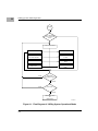
General Flow ........................................................................................... A-5
Manual Mode Connection................................................................... A-10
Terminal Mode Operation................................................................... A-12
Display System Test Errors ......................................................................... A-12
Dump Memory to Tape............................................................................... A-12
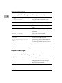
Debugger Messages ............................................................................................... B-1
Diagnostic Messages....................................................................................... B-2
Other Messages ............................................................................................... B-3
Introduction ............................................................................................................C-1
S-Record Content ...................................................................................................C-1
S-Record Types .......................................................................................................C-3
Creation of S-Records ............................................................................................C-4
VID .......................................................................................................................... D-1
CFGA ...................................................................................................................... D-1
IOSATM and IOSEATM ....................................................................................... D-3
IOSPRM and IOSEPRM ....................................................................................... D-4
IOSATW and IOSEATW....................................................................................... D-4
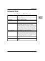
Parameter Fields.................................................................................................... D-7
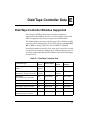
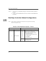
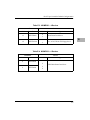
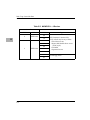
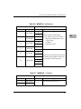
Disk/Tape Controller Modules Supported ........................................................ E-1
Disk/Tape Controller Default ConÞgurations................................................... E-2
IOT Command Parameters for Supported Floppy Types ................................ E-6
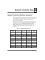
Network Controller Modules Supported ...........................................................G-1
"C" Header File ........................................................................................................ I-1
Assembly Interface Routines ................................................................................. I-7
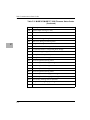
List of Tables
Table 1-1. 16XBug Assembler Addressing Modes ............................................4-10
Table 2-1. 16XBug System Call Routines..............................................................5-3
xiii
xiv
1Using the One-Line
Assembler/Disassembler
1
Introduction
Included as part of the 16XBug firmware is an
assembler/disassembler function. The assembler is an interactive
assembler/editor in which the source program is not saved. Each
source line is translated into the proper MC68040 or MC68060
machine language code and is stored in memory on a line-by-line
basis at the time of entry. In order to display an instruction, the
machine code is disassembled, and the instruction mnemonic and
operands are displayed. All valid MC68040 and MC68060
instructions are translated.
The 16XBug assembler is effectively a subset of the MC68040 and
MC68060 resident structured assemblers. It has some limitations as
compared with the resident assembler, such as not allowing line
numbers and labels; however, it is a powerful tool for creating,
modifying, and debugging MC68040 or MC68060 code.
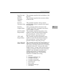
MC68040 and MC68060 Assembly Language
The symbolic language used to code source programs for
processing by the assembler is MC68040/MC68060 assembly
language. This language is a collection of mnemonics representing:
❏
Operations
-MC68040/MC68060 machine-instruction operation codes
-Directives (pseudo-ops)
❏
Operators
❏
Special symbols
1-1
Using the One-Line Assembler/Disassembler
Machine-Instruction Operation Codes
That part of the assembly language that provides the mnemonic
machine- instruction operation codes for the MPU machine
instructions is described in the appropriate microprocessor user's
manual. See the Related Documentation section in the Preface. Refer
to this manual for any question concerning operation codes.
1
Directives
Normally, assembly language can contain mnemonic directives
which specify auxiliary actions to be performed by the assembler.
The 16XBug assembler recognizes only two directives called define
constant (DC.W) and SYSCALL. These directives are used to define
data within the program, and to make calls on 16XBug utilities.
Refer to the sections on DC.W Define Constant Directive and on
SYSCALL System Call Directive, respectively, for further details.
Comparison with MC68040 and MC68060 Assemblers
There are several major differences between the 16XBug assembler
and the MC68040/MC68060 resident structured assembler. The
resident assembler is a two-pass assembler that processes an entire
program as a unit, while the 16XBug assembler processes each line
of a program as an individual unit. Due mainly to this basic
functional difference, the capabilities of the 16XBug assembler are
more restricted:
1-2
❏
Label and line numbers are not used. Labels are used to
reference other lines and locations in a program. The one-line
assembler has no knowledge of other lines and, therefore,
cannot make the required association between a label and the
label definition located on a separate line.
❏
Source lines are not saved. In order to read back a program
after it has been entered, the machine code is disassembled
and then displayed as mnemonic and operands.
❏
Only two directives (DC.W and SYSCALL) are accepted.
Source Program Coding
❏
No macro operation capability is included.
❏
No conditional assembly is used.
❏
Several symbols recognized by the resident assembler are not
included in the 16XBug assembler character set. These
symbols include > and <. Three other symbols have multiple
meanings to the resident assembler, depending on the
context (refer to the section on Addressing Modes). These are:
Asterisk (*)
Multiplication operator or current value of the program
counter.
Slash (/)
Division operator or delimiter in a register list.
Ampersand (&)
Logical operator AND or a decimal number preÞx.
Although functional differences exist between the two
assemblers, the one-line assembler is a true subset of the
resident assembler. The format and syntax used with the
16XBug assembler are acceptable to the resident assembler
except as described above.
Source Program Coding
A source program is a sequence of source statements arranged in a
logical way to perform a predetermined task. Each source
statement occupies a line and must be either an executable
instruction, a DC.W directive, or a SYSCALL assembler directive.
Each source statement follows a consistent source line format.
Source Line Format
Each source statement is a combination of operation and, as
required, operand fields. Line numbers, labels, and comments are
not used.
1-3
1
Using the One-Line Assembler/Disassembler
Operation Field
Because there is no label field, the operation field may begin in the
first available column. It may also follow one or more spaces.
Entries can consist of one of three categories:
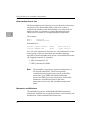
1. Operation codes which correspond to the
MC68040/MC68060 instruction set.
1
2. Define Constant directive: DC.W is recognized to define a
constant in a word location.
3. System Call directive: SYSCALL is used to call 16XBug
system utilities.
The size of the data field affected by an instruction is determined by
the data size codes. Some instructions and directives can operate on
more than one data size. For these operations, the data size code
must be specified or a default size applicable to that instruction is
assumed. The size code need not be specified if only one data size
is permitted by the operation.
The data size code is specified by a period (.), appended to the
operation field, am followed by B, W, or L, where:
B = Byte (8-bit data)
W = Word (the usual default size; 16-bit data)
L = Longword (32-bit data).
The data size code is not permitted, however, when the instruction
or directive does not have a data size attribute.
1-4
Source Program Coding
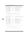
Examples (legal):
LEA
(A0),A1
ADD.B
(A0),D0
ADD
D1,D2
ADD.L
A3,D3
Longword size is assumed (.b, .w not allowed);
this instruction loads the effective address of
the Þrst operand into A1.
This instruction adds the byte whose address is
(A0) to the lowest order byte in D0.
This instruction adds the low order word of D1
to the low order word of D2. (w is the default
size code.)
This instruction adds the entire 32-bit
(longword) contents of A3 to D3.
Example (illegal):
SUBA.B
#5,A1
Illegal size speciÞcation (.b not allowed on
SUBA). This instruction would have subtracted
the value 5 from the low order byte of A1; byte
operations on address registers are not allowed.
Operand Field
If present, the operand field follows the operation field and is
separated from the operation field by at least one space. When two
or more operand subfields appear within a statement, they must be
separated by a comma.
In an instruction like ÒADD D1,D2Ó, the first subfield (D1) is called the
source effective address field, and the second subfield (D2) is called
the destination <EA> field. Thus, the contents on D1 are added to
the contents of D2 and the result is saved in register D2.
In the instruction ÒMOVE D1,D2Ó the first subfield (D1) is the sending
field and the second subfield (D2) is the receiving field.
In other words, for most two-operand instructions, the format
Òopcode source,destinationÓ applies.
1-5
1
Using the One-Line Assembler/Disassembler
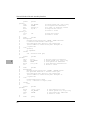
Disassembled Source Line
The disassembled source line may not look identical to the source
line entered. The disassembler makes a decision on how it
interprets the numbers used. If the number is an offset from an
address register, it is treated as a signed hexadecimal offset.
Otherwise, it is treated as a straight unsigned hexadecimal.
1
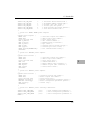
For example,
MOVE.L
MOVE.L
#1234,5678
FFFFFFFC(A0),5678
disassembles to:
00003000
00003008
21FC0000 12345678
21E8FFFC 5678
MOVE.L
MOVE.L
#$1234,($5678).W
-$4(A0),($5678).W
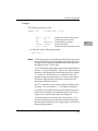
Also, for some instructions, there are two valid mnemonics for the
same opcode, or there is more than one assembly language
equivalent. The disassembler may choose a form different from the
one originally entered. As examples:
1. BRA is returned for BT
2. DBF is returned for DBRA
Note
The assembler recognizes two forms of mnemonics for
two branch instructions. The BT form (branch
conditionally true) has the same opcode as the BRA
instruction. Also, DBRA (decrement and branch
always) and DBF (never true, decrement, and branch)
mnemonics are different forms for the same
instruction. In each case, the assembler accepts both
forms.
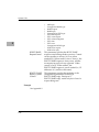
Mnemonics and Delimiters
The assembler recognizes all MC68040/MC68060 instruction
mnemonics. Numbers are recognized as binary, octal, decimal, and
hexadecimal, with hexadecimal the default case.
1-6
Source Program Coding
❏
Decimal is a string of decimal digits (0 through 9) preceded by
an ampersand (&). For example:
&12334
-&987654321
❏
Hexadecimal is a string of hexadecimal digits (0 through 9, A
through F) preceded by an optional dollar sign ($). For
example:
$AFE5
One or more ASCII characters enclosed by apostrophes (' ')
constitute an ASCII string. ASCII strings are right-justified and
zero-filled (if necessary), whether stored or used as immediate
operands.
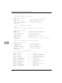
Example
00005000
00005008
0000500A
00005010
21FC0000 12345668
0053
223C41424344
3536
MOVE.L
DC.W
MOVE.L
DC.W
#$1234,($5678).W
'S'
#'ABCD',D1
'56'
The following register mnemonics are recognized/referenced by
the assembler/ disassembler:
Pseudo-Registers
R0-R7
User Offset Registers
Main Processor Registers
PC
Program Counter. Used only in forcing program
counter-relative addressing.
SR
Status Register
CCR
Condition Codes Register (Lower eight bits of SR)
USP
User Stack Pointer
1-7
1
Using the One-Line Assembler/Disassembler
1
MSP
Master Stack Pointer (MC68040 only)
ISP
Interrupt Stack Pointer (MC68040 only)
SSP
Supervisor Stack Pointer (MC68060 only)
VBR
Vector Base Register
SFC
Source Function Code Register
DFC
Destination Function Code Register
D0-D7
Data Registers
A0-A7
Address Registers. For the MC68040, Address Register
A7 represents the active System Stack Pointer, that is,
one of USP, MSP, or ISP, as speciÞed by the M and S
bits of the Status Register (SR). For the MC68060,
Address Register A7 represents the active System
Stack Pointer, that is, either USP or SSP, as speciÞed by
the S bit in the Status Register.
Floating Point Unit Registers
FPCR
Control Register
FPSR
Status Register
FPIAR
Instruction Address Register
FP0-FP7
Floating Point Data Registers
Instruction and Data Cache Registers
CACR
1-8
Cache Control Register
Source Program Coding
Memory Management Unit Registers
MMUSR
MMU Status Register (MC68040 only)
URP
User Root Pointer
SRP
Supervisor Root Pointer
TC
Translation Control Register
DTT0
Data Transparent Translation Register 0
DTT1
Data Transparent Translation Register 1
ITT0
Instruction Transparent Translation Register 0
ITT1
Instruction Transparent Translation Register 1
BUSCR
Bus Control Register (MC68060 only)
1
Character Set
The character set recognized by the 16XBug assembler is a subset of
ASCII, and these are listed as follows:
❏
The letters A through Z (uppercase and lowercase)
❏
The integers 0 through 9
❏
Arithmetic operators: + - * / << >> ! & % ^
❏
Parentheses ( )
❏
Characters used as special prefixes:
# (pound sign) specifies the immediate form of addressing.
$ (dollar sign) specifies a hexadecimal number.
& (ampersand) specifies a decimal number.
@ (commercial at sign) specifies an octal number.
% (percent sign) specifies a binary number.
' (apostrophe) specifies an ASCII literal character string.
❏
Five separating characters:
Space
, (comma)
. (period)
1-9
Using the One-Line Assembler/Disassembler
/ (slash)
- (dash)
❏
1
The character * (asterisk) indicates the current location.
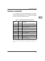
Addressing Modes
Effective address modes, combined with operation codes, define
the particular function to be performed by a given instruction.
Effective addressing and data organization are described in detail
in the section on Data Organization and Addressing Capabilities, of the
appropriate microprocessor user's manual. See the Related
Documentation section in the Preface.
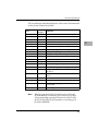
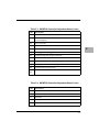
Table 4-1 summarizes the addressing modes of the MC68040 and
MC68060 which are accepted by the 16XBug one-line assembler.
Table 1-1. 16XBug Assembler Addressing Modes
1-10
Format
Description
Dn
Data register direct
An
Address register direct
(An)
Address register indirect
(An)+
Address register indirect with post-increment
-(An)
Address register indirect with pre-decrement
d(An)
Address register indirect with displacement
d(An,Xi)
Address register indirect with index, 8-bit
displacement
(bd,An,Xi)
Address register indirect with index, base
displacement.
([bd,An],Xi,od)
Address register memory indirect postindexed
([bd,An,Xi],od)
Address register memory indirect pre-indexed
address(PC)
Program counter indirect with displacement
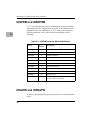
Source Program Coding
Table 1-1. 16XBug Assembler Addressing Modes
Format
Description
address(PC,Xi)
Program counter indirect with index, 8-bit
displacement
(address,PC,Xi)
Program counter indirect with index, base
displacement
([address,PC],Xi,od)
Program counter memory indirect postindexed
([address,PC,Xi],od)
Program counter memory indirect preindexed
(xxxx).W
Absolute word address
(xxxx).L
Absolute long address
#xxxx
Immediate data
1
You may use an expression in any numeric field of these addressing
modes. The assembler has a built-in expression evaluator. It
supports the following operand types:
Binary numbers
(%10
)
Octal numbers
(@765..0)
Decimal numbers
(&987..0)
Hexadecimal numbers
($FED..0)
String literals
('CHAR' )
Offset registers
(R0 - R7)
Program counter
(*)
Allowed operators are:
Addition
+
(plus)
Subtraction
-
(minus)
Multiply
*
(asterisk)
Divide
/
(slash)
1-11
Using the One-Line Assembler/Disassembler
1
Shift left
<< (left angle brackets)
Shift right
>> (right angle brackets)
Bitwise OR
!
(exclamation mark)
Bitwise AND
&
(ampersand)
Modulus
% (percent)
Exponentiate
^
(circumßex)
One's Complement
~
(tilde)
The order of evaluation is strictly left to right with no precedence
granted to some operators over others. The only exception to this
is when you force the order of precedence through the use of
parentheses.
Possible points of confusion:
❏
❏
Keep in mind that where a number is intended and it could
be confused with a register, it must be differentiated in some
way.
CLR
D0
CLR
$D0
CLR
0D0
CLR
+D0
CLR
D0+0
This means CLR.W register D0.
On the other hand, these all mean CLR.W
memory location $D0.
With the use of " * " to represent both multiply and program
counter, how does the assembler know when to use which
definition?
For parsing algebraic expressions, the order of parsing is
operand operator operand operator ...
with a possible left or right parenthesis.
Given the above order, the assembler can distinguish by
placement which definition to use. For example:
***
*+*
1-12
Means PC * PC
Means PC + PC
Source Program Coding
2**
*&&16
Means 2 * PC
Means PC AND &16
When specifying operands, you may skip or omit entries with the
following addressing modes.
❏
Address register indirect with index, base displacement.
❏
Address register memory indirect post-indexed.
❏
Address register memory indirect pre-indexed.
❏
Program counter indirect with index, base displacement.
❏
Program counter memory indirect post-indexed.
❏
Program counter memory indirect pre-indexed.
1
For modes address register/program counter indirect with index,
base displacement, the rules for omission/skipping are as follows:
❏
You may terminate the operand at any time by specifying " )".
For example:
CLR
( )
CLR
(,,)
or
is equivalent to:
CLR
❏
(0.N,ZA0,ZD0.W*1)
You may skip a field by " stepping past" it with a comma. For
example:
CLR
(D7)
is equivalent to:
CLR
($D7,ZA0,ZD0.W*1)
but
CLR
(,,D7)
is equivalent to:
CLR
(0.N,ZA0,D7.W*1)
1-13
Using the One-Line Assembler/Disassembler
1
❏
If you do not specify the base register, the default " ZA0" is
forced.
❏
If you do not specify the index register, the default "
ZD0.W*1" is forced.
❏
Any unspecified displacements are defaulted to " 0.N".
❏
The rules for parsing the memory indirect addressing modes
are the same as above with the following additions.
❏
The subfield that begins with "[" must be terminated with a
matching "]".
❏
If the text given is insufficient to distinguish between the
preindexed or postindexed addressing modes, the default is
the preindexed form.
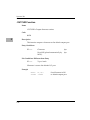
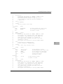
DC.W Define Constant Directive
The format for the DC.W directive is:
DC.W operand
The function of this directive is to define a constant in memory. The
DC.W directive can have only one operand (16-bit value) which can
contain the actual value (decimal, hexadecimal, or ASCII).
Alternatively, the operand can be an expression which can be
assigned a numeric value by the assembler. The constant is aligned
on a word boundary as word .w is specified. An ASCII string is
recognized when characters are enclosed inside single quotes (' ').
Each character (seven bits) is assigned to a byte of memory, with the
eighth bit (MSB) always equal to zero. If only one byte is entered,
the byte is right justified. A maximum of two ASCII characters may
be entered for each DC.W directive.
Examples are:
00010022
00010024
00010026
1-14
04D2
AAFE
4142
DC.W
DC.W
DC.W
&1234Ô
AAFE
'AB'
Decimal number
Hexadecimal number
ASCII String
Entering and Modifying Source Programs
00010028
0001002A
5443
0043
DC.W
DC.W
'TB'+1
'C'
Expression
ASCII character is
right justified
SYSCALL System Call Directive
The function of this directive is to aid you in making the TRAP #15
calls to 16XBug functions as defined in Chapter 5. The format for
this directive is:
SYSCALL function-name
For example, the following two pieces of code produce identical
results.
TRAP
DC.W
#$F
0
or
SYSCALL .INCHR
Refer to Chapter 5, System Calls, for a complete listing of all the
functions provided.
Entering and Modifying Source Programs
User programs are entered into the memory using the one-line
assembler/ disassembler. The program is entered in assembly
language statements on a line-by-line basis. The source code is not
saved as it is converted immediately to machine code upon entry.
This imposes several restrictions on the type of source line that can
be entered.
Symbols and labels, other than the defined instruction mnemonics,
are not allowed. The assembler has no means to store the
associated values of the symbols and labels in lookup tables. This
forces the programmer to use memory addresses and to enter data
directly rather than use labels.
1-15
1
Using the One-Line Assembler/Disassembler
Also, editing is accomplished by retyping the entire new source
line. Lines can be added or deleted by moving a block of memory
data to free up or delete the appropriate number of locations (refer
to the Block Move (BM) command).
1
Invoking the Assembler/Disassembler
The assembler/disassembler is invoked using the ;DI option of the
Memory Modify (MM) and Memory Display (MD) commands:
MM address ;DI
or
AS address
where <CR> sequences to next instruction
and .<CR> exits command
and
MD[S] address[:count | address];DI
or
DS address[:count | address]
The MM (;DI option), or interchangeably the AS command, is used
for program entry and modification. When this command is used,
the memory contents at the specified location are disassembled and
displayed. A new or modified line can be entered if desired. The
disassembled line can be an MPU instruction, a SYSCALL, or a
DC.W directive. If the disassembler recognizes a valid form of
some instruction, the instruction will be returned; if not (random
data occurs), the DC.W $XXXX (always hexadecimal) is returned.
Because the disassembler gives precedence to instructions, a word
of data that corresponds to a valid instruction will be returned as
the instruction.
1-16
Entering and Modifying Source Programs
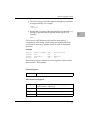
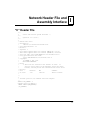
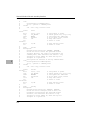
Entering a Source Line
A new source line is entered immediately following the
disassembled line, using the format discussed in the section on
Source Line Format.
167-Bug>MM 10000;DI
00010000 2600
MOVE.L
D0,D3 ?
ADDQ.L #1,A3
When the carriage return is entered terminating the line, the old
source line is erased from the terminal screen, the new line is
assembled and displayed, and the next instruction in memory is
disassembled and displayed.
167Bug>MM 10000;DI
00010000 528B
00010002 4282
ADDQ.L
CLR.L
#1,A3
D2 ?(CR)
If a hardcopy terminal is being used, port 0 should be reconfigured
for hardcopy mode for proper operation (refer to the PF command.)
In this case, the above example would look as follows:
167Bug>MM 10000;DI
00010000 2600
00010000 528B
00010002 4282
MOVE.L
ADDQ.L
CLR.L
D0,D3 ? ADDQ.L
#1,A3
D2 ? <CR>
#1,A3
Another program line can now be entered. Program entry
continues in like manner until all lines have been entered. A period
is used to exit the MM or AS command.
If an error is encountered during assembly of the new line, the
assembler displays the line unassembled with a "^" under the field
suspected of causing the error and an error message is displayed.
The location being accessed is redisplayed.
167Bug>MM 10000;DI
00010000 528B
ADDQ.L #1,A3 ? LEA.L
00010000
LEA.L
5(A0,D8),A4
-----------------------------------------^
*** Unknown Field ***
00010000 528B
ADDQ.L
5(A0,D8),A4
#1,A3 ?(CR)
1-17
1
Using the One-Line Assembler/Disassembler
Entering Branch and Jump Addresses
When entering a source line containing a branch instruction (BRA,
BGT, BEQ, etc) do not enter the offset to the branch destination in
the operand field of the instruction. The offset is calculated by the
assembler. You must append the appropriate size extension to the
branch instruction.
To reference a current location in an operand expression, the
character "*" (asterisk) can be used. Examples are:
1
00030000
00030000
00030000
00030000
60004094
60FE
4EF90003 0000
4EF00130 00030000
BRA *+$4096
BRA.B *
JMP *
JMP (*,A0,D0)
In the case of forward branches or jumps, the absolute address of
the destination may not be known as the program is being entered.
You may temporarily enter an " * " for branch-to-self in order to
reserve space. After the actual address is discovered, the line
containing the branch instruction can be re-entered using the
correct value.
Note
Branch sizes must be entered as .b or .w as opposed to .s or .l.
Assembler Output/Program Listings
A listing of the program is obtained using the Memory Display
(MD) command with the ;DI option, or interchangeably the DS
command. The MD command requires both the starting address
and the line count to be entered in the command line. When the ;DI
option is invoked, the number of instructions disassembled and
displayed is equal to the line count. The DS command will also
operate with a starting address and an ending address.
To obtain a hardcopy listing of a program, use the Printer Attach
(PA) command to activate the printer port. An MD to the terminal
then causes a listing on the terminal and on the printer.
Note again, that the listing may not correspond exactly to the
program as entered. As discussed in the section on the Disassembled
Source Line, the disassembler displays in signed hexadecimal any
number it interprets as an offset from a register; all other numbers
are displayed in unsigned hexadecimal.
1-18
2System Calls
2
Introduction
This chapter describes the 16XBug TRAP #15 handler, which allows
system calls from user programs. The system calls can be used to
access selected functional routines contained within 16XBug,
including input and output routines. TRAP #15 may also be used
to transfer control to 16XBug at the end of a user program (refer to
the .RETURN function in this chapter).
In the descriptions of some input and output functions, reference is
made to the "default input port" or the "default output port". After
power-up or reset, the default input and output port is initialized to
be port 0 (the MVME16X debug port). The defaults may be
changed, however, using the .REDIR_I and .REDIR_O functions,
as described in this chapter.
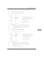
Invoking System Calls through TRAP #15
To invoke a system call from a user program, simply insert a TRAP
#15 instruction into the source program. The code corresponding
to the particular system routine is specified in the word following
the TRAP opcode, as shown in the following example.
Format in your program:
TRAP #15
DC.W $xxxx
System call to 16XBug.
Routine being requested (xxxx = code).
In some of the examples shown in the following descriptions, a
SYSCALL macro is used. This macro automatically assembles the
TRAP #15 call followed by the Define Constant for the function
code. For clarity, the SYSCALL macro is as follows:
2-1
System Calls
SYSCALL
TRAP
DC.W
ENDM
MACRO
#15
\1
Using the SYSCALL macro, the system call would appear in your
program as follows:
SYSCALL
routine name
It is, of course, necessary to create an equate file with the routine
names equated to their respective codes.
2
When using the 16XBug one-line assembler/disassembler, the
SYSCALL macro and the equates are predefined. Simply write in
SYSCALL followed by a space and the function, then carriage
return.
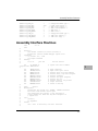
Example
167-Bug>M 03000;DI
00003000 00000000
00003000 4E4F0022
00003004 00000000
167Bug>
ORI.B #$0,D0? SYSCALL
SYSCALL .OUTLN
ORI.B #$0,D0? .
.OUTLN
String Formats for I/O
Within the context of the TRAP #15 handler there are two formats
for strings:
Pointer/Pointer Format
The string is deÞned by a pointer to the
Þrst character and a pointer to the last
character + 1.
Pointer/Count Format
The string is deÞned by a pointer to a
count byte, which contains the count of
characters in the string, followed by the
string itself.
A line is defined as a string followed by a carriage return and a line
feed: <CR><LF>.
2-2
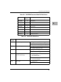
System Call Routines
System Call Routines
On entry to Firmware System Call routines, the machine state is
saved so that a subsequent ABORT or BREAK condition allows you
to resume if you wish.
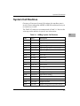
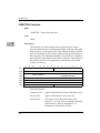
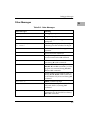
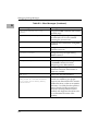
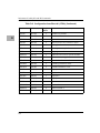
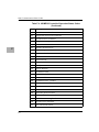
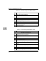
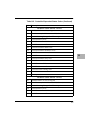
The TRAP #15 functions are summarized in Table 5-1. Refer to the
write-ups on the utilities for specific use information.
2
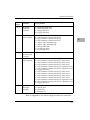
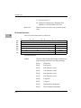
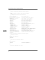
Table 2-1. 16XBug System Call Routines
Code
Name
Description
$0000
.INCHR
Input character
$0001
.INSTAT
Input serial port status
$0002
.INLN
Input line (pointer/pointer format)
$0003
.READSTR
Input string (pointer/count format)
$0004
.READLN
Input line (pointer/count format)
$0005
.CHKBRK
Check for break
$0010
.DSKRD
Disk read
$0011
.DSKWR
Disk write
$0012
.DSKCFIG
Disk conÞgure
$0014
.DSKFMT
Disk format
$0015
.DSKCTRL
Disk control
$0018
.NETRD
Read/get Þles from host
$0019
.NETWR
Write/send Þles to host
$001A
.NETCFIG
ConÞgure network parameters
$001B
.NETFOPN
Open Þle for reading
$001C
.NETFRD
Retrieve speciÞed Þle blocks
$001D
.NETCTRL
Implement special control characters
$0020
.OUTCHR
Output character
$0021
.OUTSTR
Output string (pointer/pointer format)
2-3
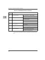
System Calls
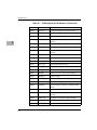
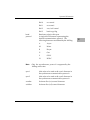
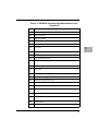
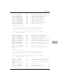
Table 2-1. 16XBug System Call Routines (Continued)
2
2-4
Code
Name
Description
$0022
.OUTLN
Output line (pointer/pointer format)
$0023
.WRITE
Output string (pointer/count format)
$0024
.WRITELN
Output line (pointer/count format)
$0025
.WRITDLN
Output line with data (pointer/count
format)
$0026
.PCRLF
Output carriage return and line feed
$0027
.ERASLN
Erase line
$0028
.WRITD
Output string with data (pointer/count
format)
$0029
.SNDBRK
Send break
$0043
.DELAY
Timer delay function
$0050
.RTC_TM
Time initialization for RTC
$0051
.RTC_DT
Date initialization for RTC
$0052
.RTC_DSP
Display RTC time and date
$0053
.RTC_RD
Read the RTC Registers
$0060
.REDIR
Redirect I/O of a TRAP #15 function
$0061
.REDIR_I
Redirect input
$0062
.REDIR_O
Redirect output
$0063
.RETURN
Return to 16XBug
$0064
.BINDEC
Convert binary to Binary Coded Decimal
(BCD)
$0067
.CHANGEV
Parse value
$0068
.STRCMP
Compare two strings (pointer/count
format)
$0069
.MULU32
Multiply two 32-bit unsigned integers
$006A
.DIVU32
Divide two 32-bit unsigned integers
$006B
.CHK_SUM
Generate checksum
System Call Routines
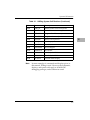
Table 2-1. 16XBug System Call Routines (Continued)
Code
Name
Description
$0070
.BRD_ID
Return pointer to board ID packet
$0071
.ENVIRON
Read/write environment parameters
$0073
.PFLASH
Program FLASH memory
$0074
.DIAGFCN
Diagnostic function(s)
$0090
.SIOPEPS
Retrieve SCSI pointers
$0120
.IOINQ
Port Inquiry
$0124
.IOINFORM
Port Inform
$0128
.IOCONFIG
Port ConÞgure
$012C
.IODELETE
Port Delete
$0130
.SYMBOLTA
Attach Symbol Table
$0131
.SYMBOLTD
Detach Symbol Table
$0140
.ACFSTAT
ACFAIL Status Inquiry
Note
2
In most examples of commands and displays given in
this manual, 167Bug is used. However, the commands,
displays, and system calls apply to all 68K CISC
debugging packages, unless otherwise noted.
2-5
System Calls
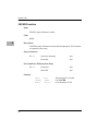
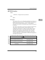
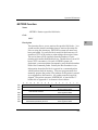
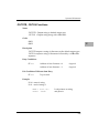
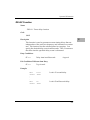
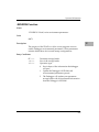
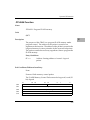
.INCHR Function
Name
INCHR - Input character routine
Code
$0000
2
Description
.INCHR reads a character from the default input port. The character
is returned in the stack.
Entry Conditions
SP ==>
Space for character.
byte
Word Þll.
byte
Exit Conditions Different from Entry
SP ==>
Character.
byte
Word Þll.
byte
Example
SUBQ.L
SYSCALL
MOVE.B
2-6
#2,A7
.INCHR
(A7)+,D0
Allocate space for result.
Call .INCHR.
Load character in D0.
System Call Routines
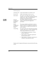
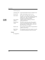
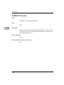
.INSTAT Function
Name
.INSTAT - Input serial port status
Code
$0001
Description
2
.INSTAT is used to see if there are characters in the default input
port buffer. The condition codes are set to indicate the result of the
operation.
Entry Conditions
No arguments or stack allocation required.
Exit Conditions Different from Entry
Z(ero) = 1 if the receiver buffer is empty.
Example
LOOP
SYSCALL
BEQ.S
SUBQ.L
SYSCALL
MOVE.B
BRA.S
.INSTAT
EMPTY
#2,A7
.INCHR
(A7)+,(A0)+
LOOP
Any characters?
No, branch.
Yes, then read them in buffer.
Check for more.
EMPTY
2-7
System Calls
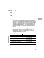
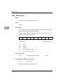
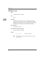
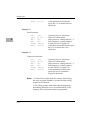
.INLN Function
Name
.INLN - Input line routine
Code
$0002
2
Description
.INLN is used to read a line from the default input port. The buffer
size should be at least 256 bytes.
Entry Conditions
SP ==>
Address of string buffer.
longword
Exit Conditions Different from Entry
SP ==>
Address of last character in the
string + 1.
longword
Example
If A0 contains the address where the string is to go;
SUBQ.L
PEA
TRAP
DC.W
MOVE.L
Note
2-8
#4,A7
(A0)
#15
2
(A7)+,A1
Allocate space for result.
Push pointer to destination
(May also invoke by SYSCALL
macro SYSCALL .INLN.)
Retrieve address of last character
+ 1.
A line is a string of characters terminated by <CR>. The
maximum allowed size is 254 characters. The
terminating <CR> is not considered part of the string,
but it is returned in the buffer, that is, the returned
pointer points to it. Control character processing as
described in the section on Terminal Input/Output
Control is in effect.
System Call Routines
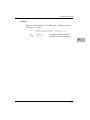
.READSTR Function
Name
.READSTR - Read string into variable-length buffer
Code
$0003
Description
2
READSTR is used to read a string of characters from the default
input port into a buffer. On entry, the first byte in the buffer
indicates the maximum number of characters that can be placed in
the buffer. The buffer size should at least be equal to that
number+2. The maximum number of characters that can be placed
in a buffer is 254 characters. On exit, the count byte indicates the
number of characters in the buffer. Input terminates when a <CR>
is received. A null character appears in the buffer, although it is not
included in the string count. All printable characters are echoed to
the default output port. The <CR> is not echoed. Some control
character processing is done:
^G
^X
^H
<DEL>
<LF>
<CR>
Bell
Cancel line
Backspace
Same as backspace
Line Feed
Carriage Return
Echoed.
Line is erased.
Last character is erased.
Last character is erased.
Echoed.
Terminates input.
All other control characters are ignored.
2-9
System Calls
Entry Conditions
SP ==>
Address of input buffer.
longword
Exit Conditions Different from Entry
SP ==>
Top of stack.
The count byte contains the number of bytes in the buffer.
2
Example
If A0 contains the string buffer address;
MOVE.B
PEA
TRAP
DC.W
MOVE.B
Note
2-10
#75,(A0)
(A0)
#15
3
(A0),D0
Set maximum string size.
Push buffer address.
(May also invoke by SYSCALL
macro SYSCALL .READSTR.)
Read actual string size.
This routine allows the caller to dictate the maximum
length of input to be less than 254 characters. If more
characters are entered, then the buffer input is
truncated. Control character processing as described in
the section on Terminal Input/Output Control is in effect.
System Call Routines
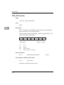
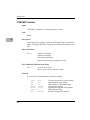
.READLN Function
Name
.READLN - Read line to fixed-length buffer
Code
$0004
Description
2
.READLN is used to read a string of characters from the default
input port. Characters are echoed to the default output port. A
string consists of a count byte followed by the characters read from
the input. The count byte indicates the number of characters in the
input string, excluding <CR><LF>. A string may be up to 254
characters.
Entry Conditions
SP ==>
Address of input buffer.
longword
Exit Conditions Different from Entry
SP ==>
Top of stack.
The first byte in the buffer indicates the string length.
Example
If A0 points to a 256 byte buffer.
PEA
SYSCALL
Note
(A0)
.READLN
Long buffer address and read a
line from default input port.
The caller must allocate 256 bytes for a buffer. Input
may be up to 254 characters. <CR><LF> is sent to
default output following echo of input. Control
character processing as described in the section on
Terminal Input/Output Control is in effect.
2-11
System Calls
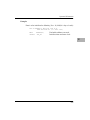
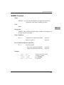
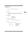
.CHKBRK Function
Name
.CHKBRK - Check for break
Code
$0005
2
Description
.CHKBRK returns "zero" status in the condition code register if
break status is detected at the default input port.
Entry Conditions
No arguments or stack allocation required.
Exit Conditions Different from Entry
Z flag set in CCR if break status is detected.
Example
SYSCALL
BEQ
2-12
.CHKBRK
BREAK
System Call Routines
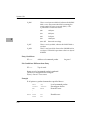
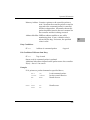
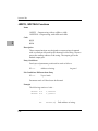
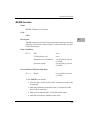
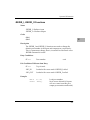
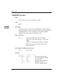
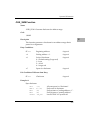
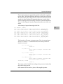
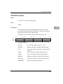
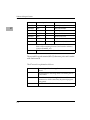
.DSKRD, .DSKWR Functions
Name
.DSKRD - Disk read function
.DSKWR - Disk write function
Code
$0010
$0011
2
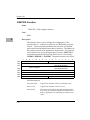
Description
These functions are used to read and write blocks of data from/to
the specified disk or tape device. Information about the data
transfer is passed in a command packet which has been built
somewhere in memory. (Your program must first manually
prepare the packet.) The address of the packet is passed as an
argument to the function. The same command packet format is
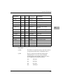
used for .DSKRD and .DSKWR. It is eight words in length and is
arranged as follows:
F
$00
E
D
C
B
A
9
Controller LUN
8
7
6
5
4
3
2
1
0
Device LUN
$02
Status Word
$04
Most Significant Word
$06
Memory Address
$08
Block Number (Disk)
Least Significant Word
Most Significant Word
or
$0A
File Number (Tape)
$0C
$0E
Least Significant Word
Number of Blocks
Flag Byte
Address Modifier
Field descriptions:
Controller LUN
Logical Unit Number (LUN) of controller to use.
Device LUN
Logical Unit Number of device to use.
2-13
System Calls
Status Word
This status word reßects the result of the operation.
It is zero if the command completed without errors.
Refer to Appendix F for meanings of returned error
codes.
Memory Address
Address of buffer in memory. On a disk read, data is
written starting at this address. On a disk write, data
is read starting at this address.
Block Number
For disk devices, this is the block number where the
transfer starts. On a disk read, data is read starting at
this block. On a disk write, data is written starting at
this block.
File Number
For streaming tape devices, this is the Þle number
where the transfer starts. This Þeld is used if the IFN
bit in the Flag Byte is cleared (refer to the Flag Byte
description). On a disk read, data is read starting at
this Þle. On a disk write, data is written starting at
this Þle.
Number of Blocks
This Þeld indicates the number of blocks to read
from the disk (.DSKRD) or to write to the disk
(.DSKWR). For streaming tape devices, the actual
number of blocks transferred is returned in this Þeld.
Flag Byte
The ßag byte is used to specify variations of the same
command, and to receive special status information.
Bits 0 through 3 are used as command bits, and bits 4
through 7 are used as status bits. For disk devices,
this Þeld must be set to zero. For streaming tape
devices, the following bits are deÞned:
2
Bit 7 is the Filemark ßag:
1
A Þlemark was detected at the end of the
last operation.
Bit 1 is the Ignore File Number (IFN) ßag:
0
The Þle number Þeld is used to position the
tape before any reads or writes are done.
1
The Þle number Þeld is ignored, and reads or
writes start at the present tape position.
Bit 0 is the End of File ßag:
2-14
System Call Routines
Address ModiÞer
0
Reads or writes are done until the speciÞed
block count is exhausted.
1
Reads are done until the count is exhausted
or until a Þlemark is found. Writes are
terminated with a Þlemark.
VMEbus address modiÞer to use while transferring
data. If zero, a default value is selected by the bug. If
nonzero, the speciÞed value is used..
2
Entry Conditions
SP ==>
Address of command packet.
longword
Exit Conditions Different from Entry
SP ==>
Top of stack.
Status word of command packet is updated.
Data is written into memory as a result of .DSKRD function.
Data is written to disk as a result of .DSKWR function.
Z(ero) = Set to 1 if no errors.
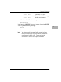
Example
If A0, A1 point to packets formatted as specified above.
PEA
SYSCALL
BNE
PEA
SYSCALL
BNE
(A0)
.DSKRD
ERROR
(A1)
.DSKWR
ERROR
Read from disk.
Branch if error.
Write to disk.
Branch if error.
.
.
.
ERROR
xxxxx
xxxxx
xxx
xxx
Handle error.
2-15
System Calls
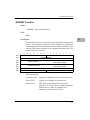
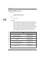
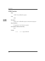
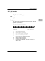
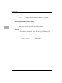
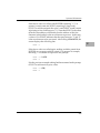
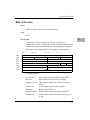
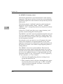
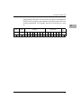
.DSKCFIG Function
Name
.DSKCFIG - Disk configure function
Code
$0012
2
Description
This function allows you to change the configuration of the
specified device. It effectively performs an "IOT under program
control". All the required parameters are passed in a command
packet which has been built somewhere in memory. The address of
the packet is passed as an argument to the function. This function
is provided for use in special applications, because .DSKCFIG is
invoked automatically the first time that a device is accessed by
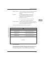
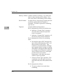
.DSKRD, .DSKWR, or .DSKFMT. The packet format is as follows:
F
$00
E
D
C
B
A
9
8
7
Controller LUN
$02
4
3
2
1
0
Most Significant Word
Memory Address
Least Significant Word
$08
0
$0A
0
$0C
0
$0E
5
Status Word
$04
$06
6
Device LUN
Flag Byte
Address Modifier
Field descriptions:
2-16
Controller LUN
Logical Unit Number (LUN) of controller to use.
Device LUN
Logical Unit Number of device to use.
Status Word
This status word reßects the result of the operation.
It is zero if the command completed without errors.
Refer to Appendix F for meanings of returned error
codes.
System Call Routines
Memory Address
Contains a pointer to a Device Descriptor Packet that
contains the conÞguration information to be
changed.
Flag Byte
This Þeld contains additional information.
Bit 0 is used to allow reading/writing the
conÞguration of the speciÞed device. It is
interpreted as follows:
Address ModiÞer
0
You can change (write) the conÞguration.
1
You can view (read) the conÞguration.
2
VMEbus address modiÞer to use while transferring
data. If zero, a default value is selected by the bug. If
nonzero, the speciÞed value is used.
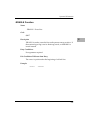
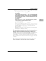
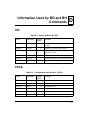
The Device Descriptor Packet format is as follows:
F
$00
E
D
C
B
A
9
8
7
Controller LUN
$02
3
2
1
0
Upper (Most Significant) Word
Parameters Mask
Lower (Least Significant) Word
Attributes Mask
Lower (Least Significant) Word
Attributes Flags
Lower (Least Significant) Word
Upper (Most Significant) Word
$0C
$0E
4
Device LUN
$08
$0A
5
0
$04
$06
6
Upper (Most Significant) Word
$10
Parameters
Field descriptions:
Most of the fields in the Device Descriptor Packet are equivalent to
the fields defined in the CFGA Configuration Area block, as
described in Appendix D. In the field descriptions following,
2-17
System Calls
reference is made to the equivalent field in the CFGA whenever
possible. For additional information on these fields, refer to
Appendix D.
Controller LUN
Same as in command packet.
Device LUN
Same as in command packet.
Parameters Mask
Equivalent to the IOSPRM and IOSEPRM Þelds, with
the lower word equivalent to IOSPRM, and the
upper word equivalent to IOSEPRM.
Attributes Mask
Equivalent to the IOSATM and IOSEATM Þelds,
with the lower word equivalent to IOSATM, and the
upper word equivalent to IOSEATM.
Attributes Flags
Equivalent to the IOSATW and IOSEATW Þelds,
with the lower word equivalent to IOSATW, and the
upper word equivalent to IOSEATW.
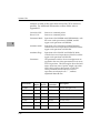
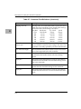
Parameters
The parameters used for device reconÞguration are
speciÞed in this area. Most parameters have an exact
CFGA equivalent. The following list shows the field
name, offset from start of packet, length, equivalent
CFGA Þeld, and short description of each Þeld.
Those parameters that do not have an exact
equivalent are indicated with " * ", and are
2
explained after the list.
2-18
Field Name
Offset
(Bytes)
Length
(Bytes)
CFGA
Equivalent
Description
P_DDS*
$10
1
-
Device descriptor size
P_DSR
$11
1
IOSSR
Step rate
P_DSS*
$12
1
IOSPSM
Sector size (encoded)
P_DBS*
$13
1
IOSREC
Block size (encoded)
P_DST*
$14
2
IOSSPT
Sectors/track
P_DIF
$16
1
IOSILV
Interleave factor
P_DSO
$17
1
IOSSOF
Spiral offset
System Call Routines
Field Name
Offset
(Bytes)
Length
(Bytes)
CFGA
Equivalent
Description
P_DSH*
$18
1
IOSSHD
Starting head
P_DNH
$19
1
IOSHDS
Number of heads
P_DNCYL
$1A
2
IOSTRK
Number of cylinders
P_DPCYL
$1C
2
IOSPCOM
Precompensation cylinder
P_DRWCYL
$1E
2
IOSRWCC
Reduced write current
cylinder
P_DECCB
$20
2
IOSECC
ECC data burst length
P_DGAP1
$22
1
IOSGPB1
Gap 1 size
P_DGAP2
$23
1
IOSGPB2
Gap 2 size
P_DGAP3
$24
1
IOSGPB3
Gap 3 size
P_DGAP4
$25
1
IOSGPB4
Gap 4 size
P_DSSC
$26
1
IOSSSC
Spare sectors count
P_DRUNIT
$27
1
IOSRUNIT
Reserved area units
P_DRCALT
$28
2
IOSRSVC1
Reserved count for alternates
P_DRCCTR
$2A
2
IOSRSVC2
Reserved count for controller
2
List notes:
P_DDS
This Þeld is for internal use only, and does not have
an equivalent CFGA Þeld. It should be set to 0.
P_DSS
This is a one byte encoded Þeld, whereas the
IOSPSM Þeld is a two byte unencoded Þeld
containing the actual number of bytes per sector.
The P_DSS Þeld is encoded as follows:
$00
128 bytes
$01
256 bytes
$02
512 bytes
$03
1024 bytes
2-19
System Calls
P_DBS
This is a one byte encoded field, whereas the IOSREC
field is a two byte unencoded field containing the
actual number of bytes per record (block). The
P_DBS field is encoded as follows
2
$00
128 bytes
$01
256 bytes
$02
512 bytes
$03
1024 bytes
$04 - $FF
Reserved encodings
P_DST
This is a two byte Þeld, whereas the IOSSPT Þeld is
one byte.
P_DSH
This is a one byte Þeld, whereas the IOSSHD Þeld is
two bytes. This Þeld is equivalent to the lower byte of
IOSSHD.
Entry Conditions
SP ==>
Address of command packet.
longword
Exit Conditions Different from Entry
SP ==>
Top of stack.
Status word of command packet is updated.
The device configuration is changed.
Z(ero) = Set to 1 if no errors.
Example
If A0 points to packet formatted as specified above.:
ERROR
2-20
PEA.L
SYSCALL
BNE
:
.
xxxxx
xxxxx
(A0)
.DSKCFIG
ERROR
Load command packet.
Reconfigure device.
Branch if error.
xxx
xxx
Handle error.
System Call Routines
.DSKFMT Function
Name
.DSKFMT - Disk format function
Code
$0014
Description
2
This function allows you to send a format command to the specified
device. The parameters required for the command are passed in a
command packet which has been built somewhere in memory. The
address of the packet is passed as an argument to the function. The
packet format is as follows:
F
$00
E
D
C
B
A
9
8
7
3
2
1
0
Most Significant Word
Memory Address
Least Significant Word
$08
Most Significant Word
Disk Block Number
$0C
$0E
4
Status Half-Word
$04
$0A
5
Device LUN
$02
$06
6
Controller LUN
Least Significant Word
0
Flag Byte
Address Modifier
Field descriptions:
Controller LUN
Logical Unit Number (LUN) of controller to use.
Device LUN
Logical Unit Number of device to use.
Status Word
This status word reßects the result of the
operation. It is zero if the command completed
without errors. Refer to Appendix F for
meanings of returned error codes.
2-21
System Calls
Memory Address Address of buffer in memory. On a disk read,
data is written starting at this address. On a
disk write, data is read starting at this address.
2
Block Number
For disk devices, when doing a format track, the
track that contains this block number is
formatted. This Þeld is ignored for streaming
tape devices.
Flag Byte
Contains additional information.
Bit 0 is interpreted as follows for disk devices:
0
Indicates a "Format Track" operation.
The track that contains the speciÞed
block is formatted.
1
Indicates a "Format Disk" operation. All
the tracks on the disk are formatted.
Bit 0 is interpreted as follows for streaming
tapes:
0
Rewinds the tape to BOT, advances the
tape without interruptions to EOT, and
then rewinds it back to BOT. Tape
retension is recommended by cartridge
tape suppliers before writing or reading
data when a cartridge has been subjected
to a change in environment or a physical
shock, has been stored for a prolonged
period of time or at extreme
temperature, or has been previously
used in a start/stop mode.
1
Selects an "Erase Tape" operation. This
completely clears the tape of previous
data and at the same time retensions the
tape.
Bit 3 is interpreted as follows:
0
2-22
The grown defect list is used when
formatting.
System Call Routines
1
The grown defect list is ignored when
formatting.
Note that the previous ßag byte operations are
still true; the operation settings are OR'd
together.
Address ModiÞer VMEbus address modiÞer to use while
transferring data. If zero, a default value is
selected by the bug. If nonzero, the speciÞed
value is used.
Entry Conditions
SP ==>
Address of command packet.
longword
Exit Conditions Different from Entry
SP ==>
Top of stack.
Status word of command packet is updated.
Example
If A0 points to packet formatted as specified above.
ERROR
PEA.L
SYSCALL
BNE
.
.
.
xxxxx
xxxxx
(A0)
.DSKFMT
ERROR
Load command packet.
Format device.
Branch if error.
xxx
xxx
Handle error.
2-23
2
System Calls
.DSKCTRL Function
Name
.DSKCTRL - Disk control function
Code
$0015
2
Description
This function is used to implement any special device control
functions that cannot be accommodated easily with any of the other
disk functions. At the present, the only defined function is SEND
packet, which allows you to send a packet in the specified format of
the controller. The required parameters are passed in a command
packet which has been built somewhere in memory. The address of
the packet is passed as an argument to the function. The packet
format is as follows:
F
$00
E
D
C
B
A
9
8
7
Controller LUN
$02
4
3
2
1
0
Status Word
Most Significant Word
Memory Address
$08
Least Significant Word
0
$0A
0
$0C
0
$0E
5
Device LUN
$04
$06
6
0
Address Modifier
Field descriptions:
2-24
Controller LUN
Logical Unit Number (LUN) of controller to use.
Device LUN
Logical Unit Number of device to use.
Status Word
This status word reßects the result of the
operation. It is zero if the command completed
without errors. Refer to Appendix F for
meanings of returned error codes.
System Call Routines
Memory Address Contains a pointer to the controller packet to
send. Note that the controller packet to send (as
opposed to the command packet) is controller
and device dependent. Information about this
packet should be found in the user's manual for
the controller and device being accessed.
Address ModiÞer VMEbus address modiÞer to use while
transferring data. If zero, a default value is
selected by the bug. If nonzero, the speciÞed
value is used.
Entry Conditions
SP ==>
Address of command packet.
longword
Exit Conditions Different from Entry
SP ==>
Top of stack.
Status word of command packet is updated.
Additional side effects depend on the packet sent to the controller.
Z(ero) = Set to 1 if no errors.
Example
If A1 points to a packet formatted as specified above;
PEA.L
SYSCALL
BNE
(A1)
.DSKCTRL
ERROR
Load command packet.
Invoke control function.
Branch if error.
xxx
xxx
Handle error.
.
.
.
ERROR
xxxxx
xxxxx
2-25
2
System Calls
.NETRD, .NETWR Functions
Name
.NETRD - Read/get from host
.NETWR - Write/send to host
Code
$0018/$0019
2
Description
These functions are used to get/send files from/to the destination
host over the specified network interface. Information about the file
transfer is passed in a command packet which has been built in
memory. (The user program must first manually prepare the
packet.) The address of the packet is passed as an argument to the
function. These functions basically behave the same as the NIOP
command, but under program control. All packets must be
longword aligned. The packet structure, NIOPCALL, is listed in
the "C" header file in Appendix I. Its format is shown below:
F
$00
E
D
C
B
A
9
8
Controller LUN
$02
2
Least Significant Word
Most Significant Word
Least Significant Word
Byte Offset
Least Significant Word
Transfer Time in Seconds (Status)
Least Significant Word
Transfer Byte Count (Status)
Least Significant Word
Most Significant Word
Most Significant Word
$14
$16
3
Maximum Length of Transfer
$10
$12
4
Most Significant Word
Data Transfer Address
$0C
$0E
5
Device LUN
$08
$0A
6
Status Word
$04
$06
7
Most Significant Word
$18
Boot Filename String
$56
2-26
$40(&64) Bytes
1
0
System Call Routines
Field descriptions:
Controller LUN
Logical Unit Number (LUN) of controller to use.
Device LUN
Logical Unit Number of device to use.
Status Word
This status word reßects the result of the
operation. It is zero if the command completed
without errors. Refer to Appendix H for
meanings of returned error codes.
Data Transfer
Address
Address of buffer in memory. On a NET read,
data is read to (received to) starting at this
address. On a NET write, data is written (sent)
starting at this address.
Length of
Transfer
The length speciÞes the number of bytes from
the "data transfer address" to transfer. A length
of 0 speciÞes to transfer the entire Þle on a read.
On a write the length must be set to the number
of bytes to transfer.
Byte Offset
The offset Þeld speciÞes the offset into the Þle
on a read. This permits users to wind into a Þle.
Transfer Time
This Þeld is status only and will be updated
only on a successful data transfer. The transfer
time will be in the number of seconds that
elapsed for the period of the data transfer.
Transfer Byte
Count
This Þeld is status only and will be updated
only on a successful data transfer. If the length
Þeld above is set to a non-zero value on a read
and the desired Þle is smaller than the desired
length, the length will be written to the actual
number of bytes transferred, up to the desired
length.
2-27
2
System Calls
Boot Filename
String
Example
2
See Appendix I.
2-28
This Þeld is the string of the name of the Þle to
load/store. On a write the Þle must exist on the
host system and also be writable (write
permission). The Þlename string must be null
terminated. The maximum length of the string
is 64 bytes inclusive of the null terminator.
System Call Routines
.NETCFIG Function
Name
.NETCFIG - Configure network parameters
Code
$001A
Description
2
This function allows you to change the configuration parameters of
the specified network interface. .NETCFIG effectively performs a
NIOT command under program control. All the required
parameters are passed in a command packet which has been built
in memory.
The address of the packet is passed as an argument to the function.
This packet contains the memory address (pointer) of the
configuration parameters to/with you wish to update/change.
The packet also contains a control flag field; this control flag
specifies the configuration operation: read, write, or write to
NVRAM. All packets must be longword aligned. The packet
structure, NIOTCALL, is listed in the "C" header file in Appendix I.
Its format is shown below:
F
$00
E
D
C
B
A
9
8
$02
4
3
2
1
0
Most Significant Word
Network Configuration Parameters Pointer
Least Significant Word
Most Significant Word
Device Configuration Parameters Pointer
$0C
$0E
5
Status Word
$08
$0A
6
Device LUN
$04
$06
7
Controller LUN
Least Significant Word
Most Significant Word
Control Flag
Least Significant Word
2-29
System Calls
Field descriptions:
2
Controller LUN
Logical Unit Number of controller to use.
Device LUN
Logical Unit Number of device to use.
Status Word
This status word reßects the result of the
operation. It is zero if the command completed
without errors. Refer to Appendix H for
meanings of returned error codes.
Network
ConÞguration
Parameters
Pointer
This pointer (address) speciÞes the location in
memory of the network conÞguration
parameters.
Device
ConÞguration
Parameters
Pointer
This pointer (address) speciÞes the location in
memory of the device conÞguration parameters.
To date no device conÞguration parameters are
used or needed.
Control Flag
This Þeld speciÞes the conÞguration parameters
operation: read, write, or write to NVRAM. The
control ßag bit deÞnitions are as follows:
0
Read configuration parameters. Pointer
specifies destination.
1
Write (update) configuration parameters.
Pointer specifies source.
2
Write (update) configuration parameters in
NVRAM. Pointer specifies source.
The Network Configuration Parameters structure has the following
format:
2-30
System Call Routines
F
E
D
C
B
A
9
$00
$02
Packet Version/Identifier
Boot File Execution Delay
2
Least Significant Word
Least Significant Word
Least Significant Word
Least Significant Word
Least Significant Word
Least Significant Word
Least Significant Word
Least Significant Word
Most Significant Word
Broadcast IP Address Mask
$30
$32
Least Significant Word
Most Significant Word
Subnet IP Address Mask
$2C
$2E
Least Significant Word
Most Significant Word
Server IP Address
$28
$2A
Least Significant Word
Most Significant Word
Client IP Address
$24
$26
0
Most Significant Word
Trace Buffer Address (TXD/RXD)
$20
$22
1
Most Significant Word
Boot File Byte Offset
$1C
$1E
2
Most Significant Word
Boot File Length
$18
$1A
3
Most Significant Word
$14
$16
4
Most Significant Word
Boot File Execution Address
$10
$12
5
Most Significant Word
Boot File Load Address
$0C
$0E
6
Most Significant Word
Node Control Memory Address
$08
$0A
7
Most Significant Word
$04
$06
8
Least Significant Word
Most Significant Word
Gateway IP Address
Least Significant Word
$34
BOOTP/RARP Retry
TFTP/ARP Retry
$36
BOOTP/RARP Control
Update Control
Boot Filename String
$40(&64) Bytes
Argument Filename String
$40(&64) Bytes
$38
$76
$78
$B6
2-31
System Calls
Field descriptions:
Node Control
Memory
Address
This parameter speciÞes the starting address of
the necessary memory needed for the transmit
and receive buffers. Currently 65,536 bytes are
needed for the speciÞed Ethernet driver
(transmit/receive buffers).
Client IP
Address
The parameter speciÞes the IP address of the
client. The Þrmware is considered to be the
client.
Server IP
Address
The parameter speciÞes the IP address of the
server. The Þrmware is considered to be the
server.
Subnet IP
Address Mask
The parameter speciÞes the subnet IP address
mask. This mask is used to determine if the
server and client are resident on the same
network. If they are not, the gateway IP address
is used as the intermediate target (server).
Broadcast IP
Address
This parameter speciÞes the broadcast IP
address that the Þrmware utilizes when an IP
broadcast needs to be performed.
Gateway IP
Address
This parameter speciÞes the gateway IP
address. The gateway address would be
necessary if the server and the client do not
reside on the same network. The gateway IP
address would be used as the intermediate
target (server).
Boot File Name
This parameter speciÞes the name of the boot
Þle to load. Once the Þle is loaded, control is
passed to the loaded Þle (program). To specify a
null Þlename, the string 'NULL' must be used.
This resets the Þlename buffer to a null
character string.
Argument File
Name
This parameter speciÞes the name of the
argument Þle. This Þle may be used by the
booted Þle (program) for an additional Þle load.
To specify a null Þlename, the string 'NULL'
must be used. This resets the Þlename buffer to
a null character string.
2
2-32
System Call Routines
Boot File Load
Address
This parameter speciÞes the load address of the
boot Þle.
Boot File
Execution
Address
This parameter speciÞes the execution address
of the boot Þle.
Boot File
This parameter speciÞes a delay value in
Execution Delay seconds before control is passed to the loaded
Þle (program).
2
Boot File
Length/Offset
These parameters behave the same as the
"Length" and "Offset" parameters associated
with the NIOP command.
BOOTP/RARP
Request Retry
This parameter speciÞes the number of the
number of retries that should be attempted
prior to giving up. A retry value of zero
speciÞes always to retry (not give up).
TFTP/ARP
Request Retry
This parameter speciÞes the number of the
number of retries that should be attempted
prior to giving up. A retry value of zero
speciÞes always to retry (not give up).
Trace Character
Buffer Address
This parameter speciÞes the starting address of
memory in which to place the trace characters.
The receive/transmit packet tracing is disabled
by default (value of 0). Any non-zero value
enables tracing. Tracing would only be used in
a debug environment and normally should be
disabled. Care should be exercised when
enabling this feature; you should ensure
adequate memory exists. The following
characters are deÞned for tracing:
?
&
*
%
$
[
]
+
(
Unknown
Unsupported Ethernet type
Unsupported IP type
Unsupported UDP type
Unsupported BOOTP type
BOOTP request
BOOTP reply
Unsupported ARP type
ARP request
2-33
System Calls
)
{
}
^
\
/
<
>
|
,
:
;
2
BOOTP/RARP
Request Control
This parameter speciÞes the BOOT/RARP
request control during the boot process. Control
can be set either to always (A) or to when
needed (W). When control is set to "always", the
BOOTP/RARP request is always sent, and the
accompanying reply always expected. When
control is set to "when needed", the
BOOTP/RARP request is sent if needed (i.e., IP
addresses of 0, null boot Þle name).
BOOTP/RARP
Replay Update
Control
This parameter speciÞes the updating of the
conÞguration parameters following a
BOOTP/RARP reply. Receipt of a
BOOTP/RARP reply would only be in lieu of a
request being sent.
Example
See Appendix I.
2-34
ARP reply
Unsupported RARP type
RARP request
RARP reply
Unsuppported TFTPtype
TFTP read request
TFTP write request
TFTP acknowledgment
TFTP data
TFTP error
Unsupported ICMP type
ICMP echo request
ICMP echo reply
2System Calls
0System Call Routines
System Call Routines
.NETFOPN Function
Name
.NETFOPN - Open file for reading
Code
$001B
Description
2
These function allows the user to open a file for reading. The
firmware basically transmits a TFTP Read Request for the specified
file and returns to the user. It is your responsibility to retrieve the
forthcoming file blocks; youwould use the .NETFRD system call to
do this. You must also perform the file block retrievals in a timely
fashion, else the TFTP server will time-out.
Information about the file open/request is passed in a command
packet which has been built in memory. (The user program must
first manually prepare the packet.) The address of the packet is
passed as an argument to the function. All packets must be
longword aligned.
The packet structure, NFILEOPEN, is listed in the "C" header file in
Appendix I. Its format is shown below:
F
$00
E
D
C
B
A
9
8
7
Controller LUN
$02
6
5
4
3
2
1
0
Device LUN
Status Word
$04
Filename String
$40(&64) Bytes
$42
Field descriptions:
Controller LUN
Logical Unit Number (LUN) of controller to use.
Device LUN
Logical Unit Number of device to use.
2-35
System Calls
2
Status Word
This status word reßects the result of the
operation. It is zero if the command completed
without errors. Refer to Appendix H for
meanings of returned error codes.
Filename String
This Þeld is the string of the name of the Þle to
load. The Þlename string must be null
terminated. The maximum length of the string
is 64 bytes, inclusive of the null terminator.
Example
See Appendix I.
2-36
System Call Routines
.NETFRD Function
Name
.NETFRD - Retrieve specified file blocks
Code
$001C
Description
2
This function allows you to retrieve the specified file blocks. You
would use this function multiple times to retrieve the entire file.
Prior to using this function a .NETFOPN system call must have
been performed. For each file block retrieved the firmware will
transmit a TFTP ACK packet to acknowledge the receipt of data.
The end of data will be signified when the number o f bytes
transferred is smaller than the block size. The block size is set at 512
bytes (TFTP convention). For each .NETFRD system call
performed, you must update (increment by one) the block number
field of the command packet. Initially the block number is one.
Information about the file block is passed in a command packet
which has been built in memory. (The user program must first
manually prepare the packet.) The address of the packet is passed
as an argument to the function. All packets must be longword
aligned. The packet structure, NFILEREAD, is listed in the "C"
header file in Appendix I. Its format is shown below:
F
$00
E
D
C
B
A
9
8
7
6
Controller LUN
$02
3
2
1
0
Status Word
Most Significant Word
Data Transfer Address
Least Significant Word
$08
Transfer Byte Count
$0A
Block Number
$0C
$0E
4
Device LUN
$04
$06
5
Most Significant Word
Data Packet (File Block) Timeout
Least Significant Word
2-37
System Calls
Field descriptions:
2
Controller LUN
Logical Unit Number (LUN) of controller to use.
Device LUN
Logical Unit Number of device to use.
Status Word
This status word reßects the result of the
operation. It is zero if the command completed
without errors. Refer to Appendix H for
meanings of returned error codes.
Data Transfer
Address
Address of buffer in memory to which to
transfer the Þle block.
Transfer Byte
Count
This Þeld is status only and will be updated
only on a successful data transfer. The size of
each Þle block is 512 bytes unless it is the last
block of the Þle (0 to 511 bytes).
Block Count
This parameter speciÞes the next expected block
number to be received.
Data Packet
Timeout
This parameter speciÞes the number of seconds
to wait before giving up control to the caller.
Example
See Appendix I.
2-38
System Call Routines
.NETCTRL Function
Name
.NETCTRL - Implement special control functions
Code
$001D
Description
2
This function is used to implement any special control functions
that cannot be accommodated easily with any of the other network
functions. At the present, the only defined packet is SEND packet,
which allows you to send a packet in the specified format to the
specified network interface driver. The required parameters are
passed in a command packet which has been built somewhere in
memory.
The address of the packet is passed as an argument to the function.
This function effectively performs an NIOC command, but under
program control. All packets must be longword aligned. The
packet structure, NIOCCALL, is listed in the "C" header file in
Appendix I. Its format is shown below:
F
$00
E
D
C
B
A
9
8
Controller LUN
$02
3
2
1
0
Least Significant Word
Most Significant Word
Memory Address (Data Transfers)
Least Significant Word
Most Significant Word
Number of Bytes (Data Transfers)
$10
$12
4
Most Significant Word
Command Identifier
$0C
$0E
5
Status Word
$08
$0A
6
Device LUN
$04
$06
7
Least Significant Word
Most Significant Word
Status/Control Flags
Least Significant Word
2-39
System Calls
Field descriptions:
2
Controller LUN
Logical Unit Number (LUN) of controller to use.
Device LUN
Logical Unit Number of device to use.
Status Word
This status word reßects the result of the
operation. It is zero if the command completed
without errors. Refer to Appendix H for
meanings of returned error codes.
Command
IdentiÞer
This parameter speciÞes the command
operation type. The command types
(identiÞers) are as follows:
0
Initialize device/channel/node
1
Get hardware (e.g., Ethernet) address
(network node)
2
Transmit (put) data packet
3
Receive (get) data packet
4
Flush receiver and receive buffers
5
Reset device/channel/node
Rules on commands:
The initialization (type 0) of the
device/channel/node must always be
performed Þrst. If you have booted or initiated
some other network I/O command, the
initialization would already have been done.
The ßush receiver and receive buffer (type 4)
would be used if, for example, the current
receive data is not longer needed, or to provide
a known buffer state prior to initiating data
transfers.
2-40
System Call Routines
The reset device/channel/node (type 5) would
be used if another operating system (node
driver) needs to be in control of the
device/channel/node. Basically, put the
device/channel/node to a known state.
Memory Address This parameter speciÞes the memory address in
which the data transfer operation (types 1, 2,
and 3) would take place from/to.
Number of Bytes This parameter speciÞes the number of bytes of
the data transfer.
Status/Control
Flags
This parameter speciÞes control and status ßags
as needed by the operation types.
Bit #16 -- Receive data transferred to user's
memory.
Example
See Appendix I.
2-41
2
System Calls
.OUTCHR Function
Name
.OUTCHR - Output character routine
Code
$0020
2
Description
This function outputs a character to the default output port.
Entry Conditions
SP ==>
Character.
byte
Word fill (placed automatically by
MPU).
byte
Exit Conditions Different from Entry
SP ==>
Top of stack.
Character is sent to the default I/O port.
Example
MOVE.B
SYSCALL
2-42
D0,-(A7)
.OUTCHR
Send character in D0
to default output port.
System Call Routines
.OUTSTR, .OUTLN Functions
Name
.OUTSTR - Output string to default output port
.OUTLN - Output string along with <CR><LF>
Codes
$0021
$0022
2
Description
.OUTSTR outputs a string of characters to the default output port.
.OUTLN outputs a string of characters followed by a <CR><LF>
sequence.
Entry Conditions
SP ==>
Address of first character +4.
longword
Address of last character + 1.
longword
Exit Conditions Different from Entry
SP ==>
Top of stack.
Example
If A0 = start of string
If A1 = end of string+1
MOVEM.L
SYSCALL
A0/A1,-(A7)
.OUTSTR
Load pointers to string
and print it.
2-43
System Calls
.WRITE, .WRITELN Functions
Name
.WRITE - Output string with no <CR> or <LF>
.WRITELN - Output string with <CR> and <LF>
Code
$0023
$0024
2
Description
These output functions are designed to output strings formatted
with a count byte followed by the characters of the string. The user
passes the starting address of the string. The output goes to the
default output port.
Entry Conditions
Four bytes of parameter positioned in stack as follows:
SP ==>
Address of string.
longword
Exit Conditions Different from Entry
SP ==>
Top of stack.
Parameter stack will have been deallocated.
Example
The following section of code ...
MESSAGE1
MESSAGE2
DC.B
DC.B
9,'MOTOROLA'
9,'QUALITY!'
.
.
.
PEA
2-44
MESSAGE1(PC)
Push address of string.
System Call Routines
SYSCALL .WRITE
PEA
MESSAGE2(PC)
SYSCALL .WRITE
Use TRAP #15 macro.
Push address of other string.
Invoke function again.
... would print out the following message:
MOTOROLA QUALITY!
Using function .WRITELN, however, instead of function .WRITE
would output the following message:
2
MOTOROLA
QUALITY!
Note
The string must be formatted such that the first byte
(the byte pointed to by the passed address) contains the
count (in bytes) of the string. There is no special
character at the end of the string as a delimiter.
2-45
System Calls
.PCRLF Function
Name
.PCRLF - Print <CR><LF> sequence
Code
$0026
2
Description
.PCRLF sends a <CR><LF> sequence to the default output port.
Entry Conditions
No arguments or stack allocation required.
Exit Conditions Different from Entry
None.
Example
SYSCALL
2-46
.PCRLF
output <CR><LF>
System Call Routines
.ERASLN Function
Name
.ERASLN - Erase Line
Code
$0027
Description
2
.ERASLN is used to erase the line at the present cursor position. If
the terminal type flag is set for hardcopy mode, a <CR><LF> is
issued instead.
Entry Conditions
No arguments required.
Exit Conditions Different from Entry
The cursor is positioned at the beginning of a blank line.
Example
SYSCALL
.ERASLN>
2-47
System Calls
.WRITD, .WRITDLN Functions
Name
.WRITD - Output string with data
.WRITDLN - Output string with data and <CR><LF>
Code
$0028
$0025
2
Description
These trap functions take advantage of the monitor I/O routine
which outputs a user string containing embedded variable fields.
You pass the starting address of the string and the address of a data
stack containing the data which is inserted into the string. The
output goes to the default output port.
Entry Conditions
Eight bytes of parameter positioned in stack as follows:
SP ==>
Address of string.
longword
Data list pointer.
longword
A separate data stack or data list arranged as follows:
Data list pointer => Data for first variable in string. longword
Data for next variable.
longword
Data for next variable.
longword
Etc.
Exit Conditions Different from Entry
SP ==>
Top of stack.
Parameter stack space will have been deallocated.
2-48
System Call Routines
Example
The following section of code ...
ERRMESSG
DC.B
$14,'ERROR CODE = |10,8Z|'
:
.
MOVE.L
PEA
PEA
SYSCALL
TST.L
#3,-(A5)
(A5)
ERRMESSG(PC)
.WRITDLN
(A5)+
Push error code on data stack.
Push data stack location.
Push address of string.
Invoke function.
Deallocate data from data stack.
... would print out the following message:
ERROR CODE = 3
Notes 1. The string must be formatted such that the first byte (the
byte pointed to by the passed address) contains the count
(in bytes) of the string (including the data field specifiers,
described in Note 2. following).
2. Any data fields within the string must be represented as
follows: "|radix,fieldwidth[Z]|Ó where radix is the base that
the data is to be displayed in (in hexadecimal, for example,
"A" is base 10, "10" is base 16, etc.) and fieldwidth is the
number of characters this data is to occupy in the output.
The data is right justified, and left-most characters are
removed to make the data fit.
The "Z" is included if you want to suppress leading zeros
in output. The vertical bars "|Ó are required characters.
3. All data is to be placed in the stack as 32-bit longwords.
Each time a data field is encountered in the user string, a
longword is read from the stack to be displayed.
4. The data stack is not destroyed by this routine. If it is
necessary that the space in the data stack be deallocated,
then this must be done by the calling routine, as shown in
the preceding example.
2-49
2
System Calls
.SNDBRK Function
Name
.SNDBRK - Send break
Code
$0029
2
Description
.SNDBRK is used to send a break to the default output port(s).
Entry Conditions
No arguments or stack allocation required.
Exit Conditions Different from Entry
Each serial port specified by current default output port list has sent
"break".
Example
SYSCALL
2-50
.SNDBRK>
System Call Routines
.DELAY Function
Name
.DELAY - Timer delay function
Code
$0043
Description
2
This function is used to generate accurate timing delays that are
independent of the processor frequency and instruction execution
rate. This function uses the onboard timer for operation. You
specify the desired delay count in milliseconds. .DELAY returns to
the caller after the specified delay count is exhausted.
Entry Conditions
SP ==>
Delay time in milliseconds.
longword
Exit Conditions Different from Entry
SP ==>
Top of stack.
Example
PEA.L
SYSCALL
&15000
.DELAY
Load a 15 second delay.
&50
.DELAY
Load a 50 millisecond delay.
.
.
.
PEA.L
SYSCALL
2-51
System Calls
.RTC_TM Function
Name
.RTC_TM - Time initialization for RTC
Code
$0050
2
Description
.RTC_TM initializes the MK48Txx Real-Time Clock with the time
that is located in a user-specified buffer.
The data input format can be either ASCII or unpacked BCD. The
order of the data in the buffer is:
H
H
M
M
S
S
s
c
↑
↑
begin buffer
HH
MM
SS
s
cc
buffer + eight bytes
Hours
Minutes
Seconds
Sign of calibration factor (+ or -)
Value of calibration factor
Entry Conditions
SP ==>
Time initialization buffer.
Exit Conditions Different from Entry
SP ==>
Top of stack.
Parameter is deallocated from stack.
2-52
c
address
System Call Routines
Example
Time is to be initialized to 2:05:32 PM with a calibration factor of
-15 (s=sign, cc=value).
Data in BUFFER is 3134 3035 3332 2D 3135 or
x1x4 x0x5 x3x2 2D x1x5. (x = don't care)
PEA.L
SYSCALL
BUFFER(PC)
.RTC_TM
Put buffer address on stack.
Initialize time and start clock.
2
2-53
System Calls
.RTC_DT Function
Name
.RTC_DT - Date initialization
Code
$0051
2
Description
.RTC_DT initializes the MK48Txx Real-Time Clock with the date
that is located in a user-specified buffer.
The data input format can be either ASCII or unpacked BCD. The
order of the data in the buffer is:
Y
Y
M
M
D
D
↑
↑
begin buffer
YY
MM
DD
d
d
buffer + six bytes
Year
Month
Day of month
Day of week (1 = Sunday)
Entry Conditions
SP ==>
Date initialization buffer.
Exit Conditions Different from Entry
SP ==>
Top of stack.
Parameter is deallocated from stack.
2-54
address
System Call Routines
Example
Date is to be initialized to Monday, Nov. 18, 1988 (d = day of week):
Data in BUFFER is 3838 3131 3138 32 or
x8x8 x1x1 x1x8 x2. (x = don't care)
PEA.L
SYSCALL
BUFFER(PC)
.RTC_DT
Put buffer address on stack.
Initialize date and start clock.
2
2-55
2System Calls
0System Call Routines
System Calls
.RTC_DSP Function
Name
.RTC_DSP - Display time from RTC
Code
$0052
2
Description
.RTC_DSP displays the date and time on the console from the
current cursor position. The format is as follows:
DAY MONTH DD, YYYY hh:mm:ss.s
Entry Conditions
No arguments or stack allocation required.
Exit Conditions Different from Entry
The cursor is left at the end of the string.
Example
SYSCALL
2-56
.RTC_DSP
Displays the day, date, and time
on the screen.
System Call Routines
.RTC_RD Function
Name
.RTC_RD - Read the RTC registers
Code
$0053
Description
2
.RTC_RD is used to read the Real-Time Clock registers. The data
returned is in packed BCD.
The order of the data in the buffer is:
Y
M
D
d
H
M
S
c
↑
begin buffer
Y
M
D
d
H
M
S
c
buffer + eight bytes
Year (2 nibbles packed BCD)
Month (2 nibbles packed BCD)
Day of month (2 nibbles packed BCD)
Day of week (2 nibbles packed BCD)
Hour of 24 hr clock (2 nibbles packed BCD)
Minute (2 nibbles packed BCD)
Seconds (2 nibbles packed BCD)
Calibration factor (MS nibble = 0 negative, 1 positive), (LS
nibble = value)
2-57
System Calls
Entry Conditions
SP ==>
Buffer address where RTC data is to longword
be returned.
Exit Conditions Different from Entry
SP ==>
Top of stack.
Buffer now contains date and time in BCD format.
2
Example
A date and time of Saturday, May 11, 1988 2:05:32 PM are to be
returned in the buffer (d = day of week, c = calibration value)
Data in buffer is 88 05 11 07 14 05 32 xx (xx = unknown)
PEA.L
SYSCALL
2-58
BUFFER(PC
.RTC_RD
Put buffer address on stack.
Read timer.
System Call Routines
.REDIR Function
Name
.REDIR - Redirect I/O function
Code
$0060
Description
2
.REDIR is used to select an I/O port and at the same time invoke a
particular I/O function. The invoked I/O function reads or writes
to the selected port.
Entry Conditions
SP ==>
Port.
word
I/O function to call.
word
Parameters of I/O function.
size speciÞed by function
(if needed)
Space for results.
size speciÞed by function
(if needed)
Exit Conditions Different from Entry
SP ==>
Result.
size speciÞed by function
(if needed)
To use .REDIR, you should:
1. Allocate space on the stack for the I/O function results (only
if required).
2. Push the parameters required for the I/O function on the
stack (only if required).
3. Push code for the desired I/O function on the stack.
4. Push the desired port number on the stack.
2-59
System Calls
5. Call the .REDIR function.
6. Pop the results off the stack (only if required).
Example
Read a character from port 1 using .REDIR
CLR.B
MOVE.W
MOVE.W
SYSCALL
MOVE.B
2
-(A7)
#$0000,-(A7)
#1,-(A7)
.REDIR
(A7)+,D0
Allocate space for results.
Load code for function .INCHR.
Load port number.
Call redirect I/O function.
Read character.
Example
Write a character to port 0 using .REDIR
2-60
MOVE.B
MOVE.W
#`A',-(A7)
#$0020,-(A7)
MOVE.W
SYSCALL
#0,-(A7)
.REDIR
Push character to write.
Load code for function
.OUTCHR.
Load port number.
Call redirect I/O function.
System Call Routines
.REDIR_I, .REDIR_O Functions
Name
.REDIR_I - Redirect input
.REDIR_O - Redirect output
Codes
$0061
$0062
2
Description
The .REDIR_I and .REDIR_O functions are used to change the
default port number of the input and output ports, respectively.
This is a permanent change, that is, it remains in effect until a new
.REDIR command is issued.
Entry Conditions
SP ==>
Port number.
word
Exit Conditions Different from Entry
SP ==>
Top of stack.
.SIO_IN
Loaded with a new mask if .REDIR_I called.
.SIO_OUT
Loaded with a new mask if .REFIR_O called.
Example
MOVE.W
SYSCALL
#1,-(A7)
.REDIR_I
Load port number.
Set it as new default (all inputs
will now come from this port,
output port remains unaffected).
2-61
System Calls
.RETURN Function
Name
.RETURN - Return to 16XBug
Code
$0063
2
Description
.RETURN is used to return control to 16XBug from the target
program in an orderly manner. First, any breakpoints inserted in
the target code are removed. Then, the target state is saved in the
register image area. Finally, the routine returns to 16XBug.
Entry Conditions
No arguments required.
Exit Conditions Different from Entry
Control is returned to 16XBug.
Example
SYSCALL
Note
2-62
.RETURN
Return to 16XBug .
.RETURN must be used only by code that was started
using 16XBug.
System Call Routines
.BINDEC Function
Name
.BINDEC - Used to calculate the Binary Coded Decimal (BCD)
equivalent of the binary number specified
Code
$0064
2
Description
.BINDEC takes a 32-bit unsigned binary number and changes it to
an equivalent BCD number.
Entry Conditions
SP ==>
Argument: Hexadecimal number.
longword
Space for result 2.
longword
Exit Conditions Different from Entry
SP ==>
Decimal number.
(two most significant DIGITS)
(eight least significant DIGITS)
longword
longword
Example
SUBQ.L
MOVE.L
SYSCALL
MOVE.L
#8,A7
D0,-(A7)
.BINDEC
(A7)+,D1/D2
Allocate space for result.
Load hex number.
Call .BINDEC.
Load resul.
2-63
System Calls
.CHANGEV Function
Name
.CHANGEV - Parse value, assign to variable
Code
$0067
2
Description
Attempt to parse value in user-specified buffer. If user's buffer is
empty, prompt user for new value, otherwise update integer offset
into buffer to skip "value". Display new value and assign to
variable unless user's input is an empty string.
Entry Conditions
SP ==>
Address of 32-bit offset into your buffer.
Address of your buffer (pointer/count format
string).
Address of 32-bit integer variable to "change".
Address of string to use in prompting and
displaying value.
Exit Conditions Different from Entry
SP ==>
Top of stack.
Example
PROMPTDC.B
GETCOUNTPEA
PEA
PEA
PEA
SYSCALL
RTS
2-64
14,'COUNT = |10,8|'
PROMPT(PC)
Point to prompt string.
COUNT
Point to variable to change.
BUFFER
Point to buffer.
POINT
Point to offset into buffer.
.CHANGEV
Make the system call.
COUNT changed, return.
System Call Routines
If the above code was called with BUFFER containing "1 3" in
pointer/count format and POINT containing 2 (longword),
COUNT would be assigned the value 3, and POINT would contain
4 (pointing to first character past "3"). Note that POINT is the offset
from the start address of the buffer (not the address of the first
character in the buffer!) to the next character to process. In this case,
a value of 2 in POINT indicates that the space between "1" and "3"
is the next character to be processed. After calling .CHANGEV, the
screen displays the following line:
COUNT = 3
If the above code was called again, nothing could be parsed from
BUFFER, so a prompt would be issued. For purpose of example,
the string "5" is entered in response to the prompt.
COUNT = 3?
COUNT = 5
5 (CR)
If in the previous example nothing had been entered at the prompt,
COUNT would retain its prior value.
COUNT = 3? (CR)
COUNT = 3
2-65
2
System Calls
.STRCMP Function
Name
.STRCMP - Compare two strings (pointer/count)
Code
$0068
2
Description
Comparison for equality is made and a Boolean flag is returned to
caller. The flag is $00 if the strings are not identical; otherwise it is
$FF.
Entry Conditions
SP ==>
Address of string 1.
Address of string 2.
Three bytes (unused).
Byte to receive string comparison result.
Exit Conditions Different from Entry
SP ==>
Three bytes (unused).
Byte to receive string comparison result.
Example
If A1 and A2 contain addresses of the two strings;
SUBQ.L
PEA
PEA
SYSCALL
MOVE.L
TST.B
BNE
2-66
#4,A7
(A1)
(A2)
.STRCMP
(A7)+,D0
D0
ARE_SAME
Allocate longword to receive result.
Push address of one string.
Push address of the other string.
Compare the strings.
Pop boolean flag into data register.
Check boolean flag.
Branch if strings are identical.
System Call Routines
.MULU32 Function
Name
.MULU32 - Unsigned 32-bit x 32-bit multiply
Code
$0069
Description
2
Two 32-bit unsigned integers are multiplied and the product is
returned as a 32-bit unsigned integer. No overflow checking is
performed.
Entry Conditions
SP ==>
32-bit multiplier.
32-bit multiplicand.
32-bit space for result.
Exit Conditions Different from Entry
SP ==>
32-bit product (result from multiplication).
Example
Multiply D0 by D1; load result into D2.
SUBQ.L
MOVE.L
MOVE.L
SYSCALL
MOVE.L
#4,A7
D0,-(A7)
D1,-(A7)
.MULU32
(A7)+,D2
Allocate space for result.
Push multiplicand.
Push multiplier.
Multiply D0 by D1.
Get product.
2-67
System Calls
.DIVU32 Function
Name
.DIVU32 - Unsigned 32-bit x 32-bit divide
Code
$006A
2
Description
Unsigned division is performed on two 32-bit integers and the
quotient is returned as a 32-bit unsigned integer. The case of
division by zero is handled by returning the maximum unsigned
value $FFFFFFFF.
Entry Conditions
SP ==>
32-bit divisor (value to divide by).
32-bit dividend (value to divide).
32-bit space for result.
Exit Conditions Different from Entry
SP ==>
32-bit quotient (result from division).
Example
Divide D0 by D1; load result into D2.
SUBQ.L
MOVE.L
MOVE.L
SYSCALL
MOVE.L
2-68
#4,A7
D0,-(A7)
D1,-(A7)
.DIVU32
(A7)+,D2
Allocate space for result.
Push dividend.
Push divisor.
Divide D0 by D1.
Get quotient.
System Call Routines
.CHK_SUM Function
Name
.CHK_SUM - Generate checksum for address range
Code
$006B
Description
2
This function generates a checksum for an address range that is
passed in as arguments.
Entry Conditions
SP ==>
Beginning address.
longword
+4
Ending address + 1.
longword
+8
Scale of checksum.
longword
0 = Default setting (longword)
1 = byte
2 = word
4 = longword
+C
Space for checksum.
longword
Exit Conditions Different from Entry
SP ==>
Checksum.
longword
Example #1
Byte checksum:
CLR.L
MOVE.L
PEA.L
PEA.L
SYSCALL
-(A7)
#1,-(A7)
(A1)
(A0)
.CHK_SUM
Allocate space for "checksum".
Push scale of checksum.
Push pointer to "ending address + 1".
Push pointer to "starting address".
Invoke TRAP #15 system call.
2-69
System Calls
MOVE.L
(A7)+,D0
Load checksum and deallocate
space, bits 7 to 0 contain the byte
checksum.
Example #2
Word hecksum:
CLR.L
MOVE.L
PEA.L
PEA.L
SYSCALL
MOVE.L
2
-(A7)
#2,-(A7)
(A1)
(A0)
.CHK_SUM
(A7)+,D0
Allocate space for "checksum".
Push scale of checksum.
Push pointer to "ending address + 1".
Push pointer to "starting address".
Invoke TRAP #15 system call.
Load checksum and deallocate space,
bits 15 to 0 contain the word
checksum.
Example #3
Longword checksum:
CLR.L
MOVE.L
PEA.L
PEA.L
SYSCALL
MOVE.L
-(A7)
#4,-(A7)
(A1)
(A0)
.CHK_SUM
(A7)+,D0
Allocate space for "checksum".
Push scale of checksum.
Push pointer to "ending address + 1".
Push pointer to "starting address".
Invoke TRAP #15 system call.
Load checksum and deallocate
space,bits 31 to 0 contain the
longword checksum.
Notes 1. If a Bus Error results from this routine, then the bug
bus error exception handler is invoked and the calling
routine is also aborted.
2. The calling routine must insure that the beginning
and ending addresses are on word boundaries or the
integrity of the checksum cannot be guaranteed.
2-70
System Call Routines
.BRD_ID Function
Name
.BRD_ID - Return pointer to board ID packet
Code
$0070
Description
2
This routine returns a pointer on the stack to the "board
identification" packet. The packet is built at initialization time and
contains information about the board and peripherals it supports.
The format of the board identification packet is shown below:
31
24
23
16
$00
$04
15
8
7
0
Eye Catcher
Revision
Month
Day
Year
$08
Packet Size
Reserved
$0C
Board Number
Board Suffix
$10
Options (coprocessor, etc.)
Family
$14
Controller LUN
Device LUN
$18
Device Type
Device Number
$1C
CPU
Option-2
Field descriptions:
Eye Catcher
Longword containing ASCII string "BDID".
Revision
Byte containing bug revision (in BCD).
Month, Day, Year Three Bytes contain date (in BCD) bug was
frozen.
Packet Size
Word contains the size of the packet.
Reserved
Reserved for future use.
Board Number
Word contains the board number (in BCD).
Board SufÞx
Word contains the ASCII board sufÞx (e.g. XT,
A, 20).
2-71
System Calls
Options:
Bits 0-3
Four bits contain CPU type:
CPU = 1 ; MC68010 present
CPU = 2 ; MC68020 present
CPU = 3 ; MC68030 present
CPU = 4 ; MC68040 present
2
CPU = 5 ; MC68060 present
CPU = 8 ; MC88100 present
CPU = 9 ; MC88110 present
Bits 4-6
Three bits contain the Family type:
Fam = 0 ; 68xxx family
Fam = 1 ; 88xxx family
Bits 7-31 The remaining bits deÞne various
board speciÞc options:
Bit 7 set = FPC present
Bit 8 set = MMU present
Bit 9 set = MMB present
2-72
Controller LUN
The Logical Unit Number for the boot device
controller (refer to Appendices E and G).
Device LUN
The Logical Unit Number for the boot device
(refer to Appendices E and G).
Device Type
The device type of the boot device (refer to the
following table).
Device Number
The number of the boot device on the controller
(refer to the following table).
Option-2
Reserved for future use (zero in this
implementation).
System Call Routines
Device
Type
Controller
0 or 1
MVME320
ST506 Disk
Controller
2 or 3
MVME327A
SCSI Controller
4 or 5
MVME350
Streaming Tape
Controller
6 or 7
MVME328
SCSI Controller
8 or 9
MVME323
ESDI Disk
Controller
Device Number
0 = Winchester hard drive
1 = Winchester hard drive
2 = Floppy disk drive
3 = Floppy disk drive
00 = SCSI Common Command Set (CCS)
10 = SCSI Common Command Set (CCS)
20 = SCSI Common Command Set (CCS)
30 = SCSI Common Command Set (CCS)
40 = Archive Viper streaming tape
50 = Archive Viper streaming tape
60 = Exabyte Mini-disk
80 = Local ßoppy drive
81 = Local ßoppy drive
2
0 = Streaming tape drive
00 = SCSI Common Command Set (CCS), direct access
08 = SCSI Common Command Set (CCS), direct access
10 = SCSI Common Command Set (CCS), direct access
18 = SCSI Common Command Set (CCS), direct access
20 = SCSI Common Command Set (CCS), sequential access
28 = SCSI Common Command Set (CCS), sequential access
30 = Floppy disk drive
40 = SCSI Common Command Set (CCS), direct access
48 = SCSI Common Command Set (CCS), direct access
50 = SCSI Common Command Set (CCS), direct access
58 = SCSI Common Command Set (CCS), direct access
60 = SCSI Common Command Set (CCS), sequential access
68 = SCSI Common Command Set (CCS), sequential access
70 = Floppy disk drive
0 = First drive
1 = Second drive
2 = Third drive
3 = Fourth drive
Refer to Appendix G for data on supported network controllers.
2-73
System Calls
Entry Conditions
SP ==>
Result.
Allocate space for ID packet address.longword
Exit Conditions Different from Entry
SP ==>
Address.
Starting address of ID packet.
2
longword
Example
PEA.L
SYSCALL
MOVE.L
2-74
(A0)
.BRD_ID
(A7)+,A0
Reserve space on stack for return value.
Board ID trap call.
Get pointer off stack.
2System Calls
0System Call Routines
System Call Routines
.ENVIRON Function
Name
.ENVIRON - Read/write environment parameters
Code
$0071
Description
2
The purpose of the TRAP is to allow a user program access to
certain Debugger environmental parameters. These parameters
include default boot devices and startup configurations.
Entry Conditions
SP ==>
+4 ==>
+8 ==>
Parameter storage buffer.
Size of the storage buffer
Operation type:
0
1
2
Size in bytes of the information the debugger
will pass.
Update the Debugger's NVRAM with
environmental parameters passed.
The Debugger will update your parameter
storage buffer with environmental information
from the Debugger's NVRAM.
2-75
System Calls
Exit Conditions Different from Entry
For operations 1 & 2,
2
Z(ero) =
Set to 1 if no errors.
Z(ero) =
Cleared if debugger has more data than the passed
buffer could hold.
Partial data transferred, or Checksum error
occurred during the write update (write only).
For operation 0,
The number of bytes required to store the debugger information
will be contained in register D0.
Description of Parameter Packets
The data contained in the parameter storage area is organized as a
set of data packets. Each data packet has the following structure:
7
0
Identifier
Number of
bytes left
in packet
data
data
2-76
System Call Routines
Currently Supported Packets and Formats
0
End of the list. (End Record)
0
0
1
Debugger Start-Up Parameters
1
2
$6
System or Bug mode ßag.
Field service menu ßag.
Remote start method ßag.
Probe system for controllers ßag.
Negate SYSFAIL always ßag.
Reset local SCSI on board reset ßag.
2
Disk Auto Boot Information
2
$15
Disk Auto Boot Enable
Disk Auto Boot at power up only
Disk Auto Boot Controller Logical Unit Number
Disk Auto Boot Device Logical Unit Number
Disk Auto Boot Abort Delay
Disk Auto Boot String to be passed to load program
($10 bytes in length)
3
ROM Boot Information
3
0C
ROM Boot Enable.
2-77
System Calls
ROM Boot at power up only
ROM Boot from VME bus
ROM Boot Abort Delay
ROM Boot Starting Address (4 bytes in length)
ROM Boot Ending Address (4 bytes in length)
4
2
NETBoot Information
4
$9
NETBoot Enable
NETBoot at power up only
NETBoot Controller Logical Unit Number
NETBoot Device Logical Unit Number
NETBoot Abort Delay
NETBoot parameter pointer (4 bytes in length)
5
Memory Size Information
5
$9
Memory Size Enable ($4E or $59)
Memory Size Starting Address (4 bytes)
Memory Size ending Address
For an explanation of each entry and definition of options, refer to
the ENV command in the Debugger manual.
The Debugger will return all parameter packets on a read. During
a write you may return only the packets that need to be updated;
however, the packet may not be returned out of order.
During an update, entries that have specific values will be verified.
If an entry is in error, that parameter will be unchanged.
2-78
System Call Routines
.PFLASH Function
Name
.PFLASH - Program FLASH memory
Code
$0073
Description
2
The purpose of this TRAP is to program FLASH memory under
program control. The address of the packet is passed as an
argument to the function. The address of the packet is passed in the
longword memory location pointed to by the current stack pointer.
The packet contains the necessary arguments/data to program the
FLASH memory.
Entry Conditions
SP ==>
Address: Starting address of control longword
packet.
Exit Conditions Different from Entry
None.
Format of flash memory control packet:
The FLASH Memory Control Packet must be longword/word (32
bit) aligned.
31
$00
24
23
16
15
Status Word
8
7
0
Control Word
$04
Source Starting Address
$08
Number of Bytes to Program
$0C
Destination Starting Address
$10
Instruction Execution Address
2-79
System Calls
Field descriptions:
2
Control/Status
Word
SpeciÞes control and status of the various
phases of the FLASH memory programming.
This parameter has two 16-bit parts: bits #31 to
#16 specify status and bits #15 to #0 specify
control.
Source Starting
Address
SpeciÞes the source starting address of the data
with which to program the FLASH memory.
Table 3-2 describes the address and range
alignment requirements for this parameter.
Number of Bytes SpeciÞes the number of bytes of the source data
to Program
(or the number bytes to program the FLASH
memory with). Table 3-2 describes the address
and range alignment requirements for this
parameter.
Destination
SpeciÞes the starting address of the FLASH
Starting Starting memory to program the source data with. Table
3-2 describes the address and range alignment
Address
requirements for this parameter.
Instruction
Execution
Address
2-80
SpeciÞes the instruction execution address to be
executed upon completion of the FLASH
memory programming. This parameter must
meet the syntax of the reset vector of the
applicable MPU architecture of the host
product. This parameter is qualiÞed with a
control bit in the control/status word; execution
will only occur when the control bit is set and no
errors occur during programming/veriÞcation.
This non-execution on error can be invalidated
by yet another control bit in the control/status
word.
System Call Routines
The next table describes the definitions of the control and status bits
in the Control/Status Word field.
Type
Control
Control
Control
Control
Control
Control
Status
Status
Status
Status
Status
Status
Status
Status
Status
Bit
Position
0
1
2
3
4
5-15
16
17
18
19
20
21
22
23
24
Status
25
Status
Status
Status
26
27-29
30
Status
31
Note
DeÞnition
Execution address valid.
Execute address on error as well.
Execute local reset.
Execute local reset on error as well.
Non-verbose, no display messages. (NOTE)
Unused, Reserved
Error of some type, see remaining status bits.
Address/Range alignment error.
FLASH Memory address range error.
FLASH Memory erase error.
FLASH Memory write error.
VeriÞcation (read after write) error.
Time-Out during erase operation.
Time-Out during byte write operation.
Unexpected manufacturer identiÞer read from
the device.
Unexpected device identiÞer read from the
device.
Unable to initialize the FLASH device to zero.
Unused, Reserved
FLASH Memory program control driver
downloaded.
No return possible to caller.
When programming the FLASH device in which the
FLASH memory is executing, bit 4 will have no effect.
All programming operations that involve the FLASH
device in which the FLASH memory is executing will
be NON-VERBOSE.
2-81
2
System Calls
.DIAGFCN Function
Name
.DIAGFCN - Diagnostic function(s)
Code
$0074
2
Description
.DIAGFCN is a system-call-like function, for the diagnostics. This
.DIAGFCN system call provides the debugger and external
software (operating systems) with a single-point-of-entry to
information maintained by the firmware diagnostics.
The .DIAGFCN system call requires a single argument, which is a
pointer to a diagfcn struct. This struct contains an Õunsigned intÕ
which is the number of the diagnostic function being requested,
and a pointer to arguments for the function to be executed:
unsigned int
char *
DIAGFCN number to execute.
Pointer to function arguments.
This system call implements the following diagnostic functions:
01: .CHKFCN (check function)
The purpose of this function is to determine whether a given
diagfcn is present in this revision of firmware. The argument
pointer in the diagfcn struct simply points to an unsigned int
variable, containing the diagfcn number to test for. If it exists, the
syscall will return zero.
02: .TESTSTAT (output test status report)
This diagcfn call allows access to selftest diagnostic results. The
calling function must supply the diagcfn call with a pointer to two
arguments (a structure containing two members):
2-82
System Call Routines
struct ts_bufps
{
unsigned int size;
void *bufptr;
}
ÔbufptrÕ points to a buffer in memory, where the first Ôsizeof(int)Õ
bytes are reserved for an integer ÔcountÕ variable, and the rest of the
buffer is reserved as a ÔcharÕ array for ASCII string data:
struct ts_bufs
{
unsigned int count;
unsigned char buf[1];
}
2
int ’size’
void *bufptr
--------------------->
int count
(char buf)
B
U
F
F
E
R
The calling function typically first makes a call with the ÔsizeÕ set to
Ôsizeof(int)Õ, and ÔbufptrÕ pointing to a section of R/W memory,
ÔsizeÕ bytes long. This causes the TESTSTAT function to calculate
how large a buffer will be required to contain the test status report.
The calculated value, plus Ôsizeof(int)Õ, will be returned in the
location pointed to by ÔbufptrÕ.
The caller will then typically allocate the number of bytes of
memory requested for the report, and call the TESTSTAT function
again. This time, the ÔsizeÕ passed in should be at least as large as the
count returned by the previous call to TESTSTAT. This function
will then recalculate the memory required, compare that to the
2-83
System Calls
amount of memory supplied, and either return an error if
insufficient buffer space has been allocated, or generate the report
and append it to the count at the location pointed to by ÔbufptrÕ.
The test result strings placed in the buffer will have the format:
<DEL><Dir_Name><DEL><Test_Name><DEL><Description><DEL><F|P|B|M|N|E><0>
Where <DEL> is a unique delimiter char and <0> is a zero. The
<F|P|B|M|N|E> is a single character:
2
F if
P if
B if
M if
N if
E if
the test has ever failed since the last reset.
the test has executed to completion without failure.
the test has been bypassed since the last reset.
the test has been masked by the operator.
the test has not been executed since the last reset.
the test is an ÔevalÕ type, and is normally not executed.
If somehow, an invalid test index is generated internal to the
debugger, a status of ? will result. This should never occur.
The N and E status is stored for each test at diag init time (on reset),
depending on whether the test is of type ÔT_TESTÓ (a ÔregularÕ test)
or ÒT_EVALÓ (a test that is only run manually). This is the only time
these values will be stored for a test. All other status types
destructively overwrite this initial value.
The M status will be saved for a test, whenever the test is executed,
if masking has been enabled for this test. It will only overwrite an N
status (and not an E).
The B status indicates a test has decided not to run, due to some
configuration limitation (an example would be when the MCECC
tests report bypassed on a CPU that only contains parity-type
RAM). The B status will overwrite the M, N, and E status.
The P status will only ever be saved, if the previous status for the
test was B, M, N, or E. A P status will never overwrite an F status. If a
test is aborted before completion, the previous status will remain,
even if the test was passing up to the point of the abort.
The F (fail) status will overwrite all other values, and will never be
changed without a reset.
2-84
System Call Routines
These status strings are appended together in the buffer supplied
by the caller. The initial delimiter character of each test result string
should be read by the calling function, and used as the character to
search for, when looking for separation between ÔwordsÕ of the
result. Each single test result string could have a different delimiter.
The <0> following each result string indicates the start of the next
result.
A hex dump of report data might look like:
100
104
114
124
134
144
154
164
174
. .
00000204
5F 72 61
57 72 69
6D 5F 61
6E 67 20
00 5F 72
72 6E 73
64 64 72
5F 72 61
.
(‘count’)
6D 5F 71 75
74 65 2F 52
6C 74 73 5F
4F 6E 65 73
61 6D 5F 70
5F 4E 00 5F
65 73 73 61
6D 5F 63 6F
2
69
65
41
2F
61
72
62
64
6B
61
6C
5A
74
61
69
65
5F
64
74
65
73
6D
6C
5F
51
5F
65
72
5F
5F
69
43
75
4E
72
6F
50
61
74
6F
69
00
6E
65
61
64
79
64
63
5F
61
73
74
72
5F
65
6B
72
74
5F
74
5F
4E
20
20
61
69
4E
65
41
00
45
_ram_quik_Quick
Write/Read_N._ra
m_alts_Alternati
ng Ones/Zeroes_N
._ram_pats_Patte
rns_N._ram_adr_A
ddressability_N.
_ram_code_Code E
This function will return an integer status. Zero is returned upon
success. A result of -1 is returned if an error in the system call
function occurred:
if ( 0 <= size < 4 )
return -1;
if ( size == 4 )
write ‘count’ to ‘bufptr’ location in RAM
return 0;
if ( 4 < size < count )
write ‘count’ to ‘bufptr’ location in RAM
return -1;
if ( count <= size )
write ‘count’ to ‘bufptr’ location in RAM
write status report to ‘bufptr +
sizeof(int)’ in RAM
return 0;
The return result is handled according to the processor family that
the code is being run on.
68K: returned on the stack in place of the supplied pointer.
2-85
System Calls
03: .MEMSTAT (memory status)
This function implements a report mechanism for main memory
diagnostics. This report is always of a fixed size, and can therefore
be called by higher level software that can not dynamically allocate
buffer space.
This function reports ÒcombinedÓ status for each of certain test
directories. This list includes ÒRAMÓ, ÒMCECCÓ, ÒMEMC1Ó,
ÒMEMC2Ó, ÒECCÓ, and possibly others as new hardware/software
is developed.
2
In the case of ÒRAMÓ tests, they cover a range of memory, and
typically contain nothing that is board-specific.
The ÒMCECCÓ and ÒECCÓ tests do contain board-specific code, and
will cover segments of memory, rather than a single range. In this
case, these tests will likely appear in the report multiple times, once
for each segment of memory.
Since the test is only ever run once, over all segments, the status
result will be identical for all reported instances. If one of the
segments covered does not contain an ECC type of memory board,
the results will contain a zero address range (beginning address =
ending address).
The ÒMEMC?Ó tests are on a per-board basis. These tests are
intended for the parity memory board, but contain one or more
tests that are also appropriate for the MCECC memory board. Each
test covers one segment of memory on the board under test. This
report may return ÒNÓ (for Ònot executedÓ), ÒBÓ (for ÒbypassedÓ),
ÒPÓ (for ÒpassedÓ), or ÒFÓ (for ÒfailedÓ).
1. Walk down through the diag directory, looking for test
groups that match our list.
2. When a match is found, walk down through the tests, ignore
any functions that are not of the type ÒT_TESTÓ, check the
status for each test (using the Òtest indexÓ to look in the
diagctl ÒteststatÓ array).
2-86
System Call Routines
3. Create an overall status for the test group. The status should
be a single char in the set: {P,F,N,B}, where:
P - PASSED
Only returned when all of the ÒT_TESTÓ type functions in the
test group have posted a ÔpassedÕ status. Any test in the group
posting other than ÔpassedÕ will cause a different result than
P to be returned.
F - FAILED
If any test of type ÒT_TESTÓ in the test group has posted a
ÔfailedÕ status, the result returned will be F.
N - NOT EXECUTED
If any test in the group, of type ÒT_TESTÓ was not executed,
this status should be returned, unless any of the tests posted
a ÔfailedÕ status, in which case an F should be returned.
B - BYPASSED
Returned if all of the ÒT_TYPEÓ functions in the test group
have posted a ÒbypassedÓ status.
The upper address bound and lower address bound passed back to
the caller, should be initialized to the values of ÒMemory Size
Ending AddressÓ and ÒMemory Size Starting AddressÓ from
NVRAM. These values to be returned should be overridden by any
test config parameters (CF params) that might exist for the
applicable test. A function will be inserted in each of the memory
test groups that can be called and will return the upper and lower
bounds.
The argument pointer in the diagfcn struct points to the report
buffer. This buffer is 452 bytes long, and has the structure:
2-87
2
System Calls
Entry 1
Entry 2
2
Entry 16
unsigned int
/unsigned int
|unsigned int
|unsigned int
\char[16]
/unsigned int
|unsigned int
|unsigned int
\char[16]
:
.
/unsigned int
|unsigned int
|unsigned int
\char[16]
# valid entries
upper addr bound
lower addr bound
combined test stat (P|F|N|B)
test group name (NULL terminated)
upper addr bound
lower addr bound
combined test stat (P|F|N|B)
test group name (NULL terminated)
upper addr bound
lower addr bound
combined test stat (P|F|N|B)
test group name (NULL terminated)
MEMSTAT will return a zero from the system call if there were no
errors.
04: .ST_NMLIST (selftest name list)
This function will walk through the selftest directory structure, and
generate a report consisting of test and group names that are
present.
The report contains test group name, as well as the specific test
name. Format of the list is the same as that for the Ò.TESTSTATÓ
diag syscall.
Each string in the list begins with the separator (unique delimiter
character) that is to be used in the current line. The Òtest group
nameÓ comes next, followed by a separator. Next is the Òtest nameÓ,
followed by a NULL (Õ\0Õ). For example: #ram#pats<0>
The caller must provide a pointer to a structure when calling this
function. The structure first contains an ÕintÕ (4 bytes) giving the size
of an available buffer to be used for output from this function. This
ÕintÕ is immediately followed by the address (4 bytes) of the start of
the buffer.
2-88
System Call Routines
If this function is called with the ÕsizeÕ set to Õsizeof(int)Õ (4), then
this function will return a single integer (4 bytes) in the buffer,
containing the size of buffer needed to contain the list and the size.
To get the list, the function needs to be called with a buffer ÕsizeÕ at
least as large as is reported in the first call. Anything smaller will
result in a non-zero return status, and the list will not be generated.
For 68K debuggers, the caller should place the structure pointer on
the stack. An integer result will be returned, in place of the pointer
passed in to this routine. A zero (0) result indicates success, nonzero indicates failure.
int ’size’
void *bufptr
--------------------->
int count
(char buf)
B
U
F
F
E
R
Entry Conditions
SP ==>
Points to location containing the diagcfn struct
address.
Exit Conditions Different from Entry
An integer status to the higher level is returned on the stack in place
of the supplied pointer.
2-89
2
System Calls
.SIOPEPS Function
Name
.SIOPEPS - Retrieve SCSI pointers (167/187 only)
Code
$0090
2
Description
The purpose of this TRAP is to allow a user program toaccess the
SCSI I/O Processor package contained in the Debugger ROMs.
This TRAP returns a list of pointers and table sizes that the user
program uses to move the SCSI I/O Processor package from ROM
to RAM. The SIOP package cannot be executed by a user program
without being moved and edited. For instructions on how to move
and edit the SIOP package, refer to the SIOP user's manual.
Entry Conditions
None
Exit Conditions Different from Entry
SP ==>
Pointer to the SIOP pointer and size table.
Description of siop pointer and size table packet:
Format for packet containing SIOP pointers and table sizes. All
entries are 4 bytes in length.
2-90
siop_init
Initialization routine entry.
siop_cmd
Command entry point entry.
siop_int
Interrupt handler entry.
sdt_tinit
SIOP debug trace initialization entry.
sdt_alloc
SIOP debug trace memory allocation entry.
relocation
Pointer to the relocation table for NCR scripts.
System Call Routines
script_ptr
Pointer to the NCR scripts index pointer array.
script_ptr_sz
Size of the NCR scripts index pointer array.
script_array_sz
Size of the scripts array.
2
2-91
System Calls
.IOINQ Function
Name
.IOINQ - Port Inquire
Code
$0120
2
Description
Writes the Port Control Structure at the user-specified address. The
Port Control Structure contains I/O Port Concurrent Mode and
Port Control information about the named port.
Entry Conditions
SP ==>
Pointer to Port Control Structure as defined below.
The Port Number, Board Name Pointer, and I/O Control Structure
Pointer members of the Port Control Structure must be USER
initialized before calling .IOINQ.
Exit Conditions Different from Entry
SP ==>
Pointer to Port Control Structure as deÞned below,
or
SP ==>
NULL (Port not recognized error).
The Port Control Structure will be modified as described above.
2-92
System Call Routines
Port Control Structure
The Port Control Structure is of the form:
31
24
23
16
15
8
$00
Port Number
$04
Board Name Pointer
$08
Channel
$0C
Device Address
$10
Concurrent Mode
$14
Modem ID
$18
I/O Control Structure Pointer
$1C
Error Code
$20
Reserved
$24
Reserved
$28
Reserved
7
0
2
Field descriptions:
Port Number
Board Name
Pointer
The Port Number as used here is analogous to
the port number as required by the 16XBug Port
Format (PF) command. Port Numbers are
assigned as follows:
$FFFFFFFE
Concurrent Port
$FFFFFFFF
System Console
$0 - $1F
Other currently assigned port
A pointer to a null ($00) terminated ASCII string
which is the name of the board (module) that is
host to the target Device. The maximum length
of this string is 20 bytes. The Board Name as
used here is analogous to the board name as
required by the 16XBug Port Format (PF)
command. The following boards are currently
supported:
MVME050
System Controller Module
2-93
System Calls
2
MVME162
Embedded Controller
Module
MVME172
Embedded Controller
Module
MVME166
Single Board Computer
MVME167
Single Board Computer
MVME176
Single Board Computer
MVME177
Single Board Computer
MVME335
Serial and Parallel I/O
Module
Channel
On multi-port devices, this value speciÞes
which port of the device is being referenced.
Zero inclusive port numbering is assumed, i.e.,
Port A is Channel Number 0.
Device Address
Base address of the I/O Device.
Concurrent
Mode
Nonzero Value ßags concurrent mode operation
of this port. Zero ßags normal operation for this
port.
Modem ID
Modem identiÞcation code for the modem
associated with this port. The Modem ID code is
ONLY valid if Concurrent Mode Operation is
true for this port. The following modems are
currently supported:
Modem ID
2-94
Modem Type
1
Non-intelligent modem
2
Terminal Mode - Refer to
Appendix A, System Mode
Operation, the section on
Initiate Service Call.
3
UDS 2662
4
UDS 2980
5
UDS 3382
System Call Routines
I/O Control
A pointer to the port parameter/conÞguration
Structure Pointer table. The I/O Control Structure is deÞned
below.
Error Code
Contains error code if any. The following error
codes are currently deÞned:
1. PF Error - Couldn't format the Port with the
user's parameters.
2. Port Number not recognized, that is, the
16XBug does not have a deÞnition for the
given Port Number.
3 Synchronization Error - can't turn on
Concurrent Mode (CM) (CM already on).
4 16XBug has no deÞnition for the Port
Number speciÞed.
5 Port Number not in range of -2 to $1F.
6 No info available on CM port because CM
not active.
7. All legal Port Numbers are currently in use.
8. All device driver Control Structures are
currently in use. Can't deÞne any more Port
Numbers.
9. Synchronization Error - can't turn off CM.
CM is already off.
10. Contradictory Request. CM port number
speciÞed but user's CM ßag is clear and no
16XBug port is currently operating in CM.
11. Illegal Port number for .IODELETE trap call.
12. Alias for Error #11.
13. IODELETE is not allowed to delete this port
(16XBug default port(s)).
14. Alias for Error #8.
2-95
2
System Calls
15. Alias for Error #7.
16. Unknown modem type. Returned Port
Number is valid, but CM is NOT set.
Reserved
These locations are set to zero on return to the
caller.
I/O Control Structure
2
The I/O Control Structure is of the form:
31
24
23
16
$00
15
8
7
0
ctrlbits
$04
baud
$08
00
00
00
protocol
$0C
00
00
00
sync1
$10
00
00
00
sync2
$14
00
00
00
xonchar
$18
00
00
00
xoffchar
Field descriptions:
ctrlbits
2-96
The bits of this 32-bit wide integer are deÞned as
high true ßags with the following meanings:
Bit 00
Odd parity
Bit 01
Even parity
Bit 02
8 bit character word
Bit 03
7 bit character word
Bit 04
6 bit character word
Bit 05
5 bit character word
Bit 06
2 stop bits
Bit 07
1 stop bit
Bit 08
Data terminal equipment
Bit 09
Data computer equipment
System Call Routines
Bit 10
cts control
Bit 11
rts control
Bit 12
xon/xoff control
Bit 13
hard copy ßag
baud
Baud rate value for this port.
protocol
A single ASCII character representing the
desired communications protocol. The
following characters are deÞned by the 16XBug.
Note
A
Async
M
Mono
B
Bisync
G
Gen
S
SDLC
H
HDLC
Only the asynchronous protocol is supported by the
16XBug at this time.
sync1
8 bit value to be used as the sync1 character in
the synchronous communication protocols.
sync2
8 bit value to be used as the sync2 character in
the synchronous communication protocols.
xonchar
Software ßow (on) control character.
xoffchar
Software ßow (off) control character.
2-97
2
System Calls
.IOINFORM Function
Name
.IOINFORM - Port Inform
Code
$0124
2
Description
This trap will inform the 16XBug about change in I/O Port
operation. The 16XBug updates its internal I/O control structures
and writes ERROR CODE and (possibly) PORT NUMBER in your
Port Control Structure.
If you wish to inform the 16XBug that you are "turning on"
Concurrent Mode (CM), you must set the Concurrent Mode field of
the Port Control Structure. It is permissible to use a Port number of
-2 when "turning on" CM. The 16XBug will return a valid Port
Number for your future reference. If you wish to inform the
16XBug that you are "turning off" CM operation, you must use a
PORT NUMBER that has been returned by the .IOINQ or
.IOINFORM system calls.
Entry Conditions
SP ==>
Pointer to the Port Control Structure.
All members of the Port Control Structure, except ERROR CODE
and RESERVED, as well as the BOARD NAME STRING and I/O
CONTROL STRUCTURE must be USER initialized before calling
.IOINFORM.
Exit Conditions Different from Entry
SP ==>
Pointer to the Port Control Structure, or
SP ==>
NULL (Port not recognized error).
The Port Control Structure will be modified as described above.
2-98
System Call Routines
.IOCONFIG Function
Name
.IOCONFIG - Port Configure
Code
$0128
Description
2
This trap will instruct the 16XBug to access the I/O device to
change port operation and to update its internal I/O Control
structures. The 16XBug writes ERROR CODE and (possibly) PORT
NUMBER in your Port Control Structure.
If you wish to inform the 16XBug that you are "turning on"
Concurrent Mode (CM), you must set the Concurrent Mode field of
the Port Control Structure. It is permissible to use a Port number of
-2 when "turning on" CM. The 16XBug will return a valid Port
Number for your future reference.
If you wish to inform the 16XBug that you are "turning off" CM
operation, you must use a PORT NUMBER that has been returned
by the .IOINQ or .IOINFORM system calls.
Entry Conditions
SP ==>
Pointer to Port Control Structure as deÞned above.
All members of the Port Control Structure, except ERROR CODE
and RESERVED, as well as the BOARD NAME STRING and I/O
CONTROL STRUCTURE must be USER initialized before calling
.IOCONFIG.
2-99
System Calls
Exit Conditions Different from Entry
SP ==>
Pointer to Port Control Structure as deÞned above,
or
SP ==>
NULL (Port not recognized error).
The Port Control Structure will be modified as described above.
2
2-100
System Call Routines
.IODELETE Function
Name
.IODELETE - Port Delete
Code
$012C
Description
2
Causes the 16XBug to delete the named I/O port from its internal
port list. The function of this call is analogous to the 16XBug NOPF
command. Note that .IODELETE cannot delete the Concurrent
port. You must first use the .IOINFORM trap and then you may
delete the port.
Entry Conditions
SP ==>
Pointer to Port Control Structure as defined above.
The Port Number member of the Port Control Structure must be
USER initialized before calling .IODELETE. The Board Name
Pointer, Channel, Device Address, Concurrent Flag, Modem ID,
and, I/O Control Pointer members of the Port Control Structure are
not used by this trap.
Exit Conditions Different from Entry
SP ==>
Pointer to Port Control Structure as deÞned above,
or
SP ==>
NULL (Port not recognized error).
The Port Control Structure Error Code field will be written with an
error code if any errors occurred.
2-101
System Calls
.SYMBOLTA Function
Name
.SYMBOLTA - Attach Symbol Table
Code
$0130
2
Description
This routine attaches a symbol table to the BUG. Once a symbol
table has been attached, all displays of physical addresses are first
looked up in the symbol table to see if the address is in range of any
of the symbols (symbol data). If the address is in range, it is
displayed with the corresponding symbol name and offset (if any)
from the symbol base address (symbol data). In addition to the
display, any command line input that supports an address as an
argument can now take a symbol name for the address argument.
The address argument is first looked up in the symbol table to see
if it matches any of the addresses (symbol data) before conversion
takes place. This command is analogous to the BUG command
SYM. Refer to Chapter 3 for the command description.
The format of the symbol table is shown below:
31
$00
24
23
16
15
$04
Symbol Data #0
$08
Symbol Name #0
$20
Symbol Data #1
$24
Symbol Name #1
2-102
8
Number of Entries in Symbol Table
7
0
System Call Routines
Field descriptions:
Number of
Entries in
Symbol Table
The number of entries in table.
Symbol Data
32-bit hexadecimal value.
Symbol Name
A string of printable characters; may be null
($00) terminated.
The symbol data fields must be ascending in value (sorted
numerically). Upon execution of the system call, the BUG performs
a sanity check on the symbol table with the above rules. The
symbol table is not attached if the check fails.
Entry Conditions
SP ==>
Address -- Starting address of
symbol table.
word
Exit Conditions Different from Entry
SP ==>
Address -- Starting address of
symbol table
Z=
0 if errors (sanity check failed).
Z=
1 if not errors.
word
2-103
2
System Calls
.SYMBOLTD Function
Name
.SYMBOLTD - Detach Symbol Table
Code
$0131
2
Description
This routine detaches a symbol table from the BUG. This command
is analogous to the BUG command NOSYM. Refer to Chapter 3 for
the command description.
Entry Conditions
None.
Exit Conditions Different from Entry
None.
2-104
System Call Routines
.ACFSTAT Function
Name
.ACFSTAT - ACFAIL status inquiry
Code
$0140
Description
2
This routine will return status indicating whether or not this
powerup followed an ACFAIL shutdown. A pointer is returned
that points to the ACFAIL status packet.
The format of the ACFAIL status packet is shown below:
31
24
23
16
15
8
7
0
$00
STATUS
MONTH
DAY
YEAR
$04
HOUR
MINUTE
SECOND
RESERVED
Field descriptions:
STATUS
0 = ACFAIL condition false, 1 = true.
MONTH
Month of ACFAIL condition (BCD format).
DAY
Day of the Month of ACFAIL condition (BCD
format).
YEAR
Year of ACFAIL condition (BCD format).
HOUR
Hour of ACFAIL condition (BCD format).
MINUTE
Minute of ACFAIL condition (BCD format).
SECOND
Seconds of ACFAIL condition (BCD format).
RESERVED
Reserved (alignment purposes).
2-105
System Calls
Entry Conditions
None.
Exit Conditions Different from Entry
SP ==>
2
2-106
Address -- Starting address of
ACFAIL status packet.
word
A16XBug System Mode
A
Operation
General Description
To provide compatibility with the Motorola Delta Series systems,
the 16XBug has a special mode of operation that allows the
following features to be enabled:
❏
Extended confidence tests that are run automatically on
power-up or reset of the MVME16X.
❏
A menu that allows several system start up features to be
selected, such as:
Ð Continue System Start Up
Ð Select Alternate Boot Device
Ð Go to System Debugger
Ð Initiate Service Call
Ð Display System Test Errors
Ð Dump Memory to Tape
❏
Return to the menu upon system start up errors instead of
return to the debugger.
❏
Enabling of the Bug autoboot sequence.
The flow of system mode operation is shown in Figure A-1. Upon
either power up or system reset, the MVME16X first executes a
limited confidence test suite. This is the same test suite that the Bug
normally executes on power up when not in the system mode.
A-1
A
16XBug System Mode Operation
Upon successful completion of the limited confidence tests, a five
second period is allowed to interrupt the autoboot sequence. By
typing any character you can cause the module to display the
Service Menu permitting the selection of an alternate boot device,
entry to the debugger, etc., as described above.
Upon selection of "continue start up" the module conducts a more
extensive confidence test. Successful completion of the extended
confidence test initiates the autoboot sequence, with boot taking
place either from the default device (refer to Chapter 3 for
information on entering/changing the default boot device) or from
the selected boot device if an alternate device has been selected.
If the limited confidence test fails to complete correctly, it may
display an error message. Explanations of these error messages can
be found in Appendix B. Some error message explanations for the
extended confidence test are given in the 16XBug board-specific
debugger manual under the heading for the failed test.
Service Menu Details
The Service Menu lists these function choices:
1)
2)
3)
4)
5)
6)
Continue System Start Up
Select Alternate Boot Device
Go to System Debugger
Initiate Service Call
Display System Test Errors
Dump Memory to Tape
To select one of the functions, enter the number and press the
Return or Enter key. The following paragraphs give more detailed
descriptions of the menu selections.
Continue System Start Up
Enter 1 <CR> to select ÒContinue System Start UpÓ.
A-2
Service Menu Details
No other action is required from you. The system then continues
the start up process by initializing extended confidence testing
followed by a system boot.
A-3
A
A
16XBug System Mode Operation
SYSTEM
WAIT 5 SECONDS
FOR ANY CHARACTER
TO HALT
DISPLAY SERVICE MENU
CONTINUE START-UP
DISPLAY ERRORS
SELECT ALTERNATE
BOOT DEVELOPMENT
DUMP MEMORY
TO TAPE
SYSTEM DEBUGGER
START CONVERSATION
MODE
SERVICE CALL
EXIT CONCURRENT
MODE
ERROR
EXTENSIVE
SYSTEM SELF TEST
NO ERRORS
ERROR
BOOTLOADER
NO ERRORS
OPERATING SYSTEM
OR
DIAGNOSTICS
fc010 9211
Figure A-1. Flow Diagram of 16XBug System Operational Mode
A-4
Service Menu Details
Select Alternate Boot Device
Enter 2 <CR> to select ÒSelect Alternate Boot DeviceÓ.
You are prompted with:
"Enter Alternate Boot Device:
Controller:
Drive
:
File
:".
The selection of devices supported by the 16XBug is listed in
Appendix E. Entering a selected device followed by a <CR>
redisplays the menu for another selection, normally "Continue
System Start Up" at this point.
Go to System Debugger
Enter 3 <CR> to select ÒGo to System DebuggerÓ.
This places you in 16XBugÕs diagnostic mode, indicated by the
prompt 16X-Diag>. When you are in 16X-Diag mode, operation is
defined by sections of this manual dealing with the Bug and FAT
diagnostics.
If you wish to return to the Service Menu, type menu <CR>when
the Bug prompt appears.
Initiate Service Call
Enter 4 <CR> to select the ÒInitiate Service CallÓ function.
This function is described in the following paragraphs.
General Flow
The ÓInitiate Service CallÓ function is normally used to complete a
connection to a customer service organization (CSO) which can
then use the "dual console" mode of operation to assist a customer
with a problem. Interaction with the service call function proceeds
as follows:
A-5
A
A
16XBug System Mode Operation
First, the system asks
"Modem Type:
0) Terminal
1) Manual
2) UDS-2122662
3) UDS-2122980 (Hayes)
4) UDS-2123382 (Hayes)
Your Selection ( )?".
Explanation:
Terminal mode is used to connect any ASCII terminal in place of a
modem, via a null modem, or equivalent cable. It is useful in certain
trouble- shooting applications for providing a slave terminal
without the necessity of dialing through a modem.
Manual mode connects directly to the modem in an ASCII terminal
mode, allowing any nonstandard protocol modem to be used.
UDS means that the modem is compatible with the UDS modem
protocol as used in internal Delta Series modems. The model
number of this modem is UDS 2122662.
Hayes means that the modem is compatible with a minimal subset
of the Hayes modem protocol. This minimum subset is chosen to
address the broadest spectrum of Hayes compatible modem
products. Note that the modem itself is not tested when Hayes
protocol is chosen, while the modem is tested with the UDS
protocol choice.
When a selection of one of the above options is made (option 0 in
this example), the system asks:
Do you want to change the baud rate from 1200 (Y/N)?
Note that any question requiring a Y or N answer defaults to the
response listed furthest to the right in the line (i.e., a question with
Y/N defaults to NO if only a carriage return is entered). If you
answer Y to the baud rate question, the system prompts:
Baud rate [300, 1200, 2400, 4800, 9600] 1200?
A-6
Service Menu Details
You should enter a selected baud rate, such as 300, and type a
return. A return only leaves the baud rate as previously set. The
system then asks:
Is the modem already connected to customer service (Y/N)?
When a connection has been made to Customer Service (or any
other remote device), hang up does not automatically occur; it is an
operation that you must initiate. If a system reset has occurred, for
instance, a hang up does not take place, and connection to CSO is
still in effect. In this case, it is not necessary or desirable to attempt
to reconnect on a connection that is already in effect.
When an answer is entered to the question, the system responds:
Enter System ID Number:
This number is one assigned to the user system by its affiliated
Customer Service Organization. The system itself does not care
what is entered here, but the Customer Service computer may do a
check to assure the validity of this number for login purposes. The
system responds with:
Wait for an incoming Call or Dial Out (W/D)?
You have the option of either waiting for the other computer to dial
in to complete the connection, or dialing out itself. If you selected
W, then skip the next two steps. If you selected D, the system asks:
Hayes Modem:
(T) = Tone Dialing (Default), (P) = Pulse Dialing
(,) = Pause and Search for a Dial Tone
UDS Modem:
(T) = Tone Dialing (Default), (P) = Pulse Dialing
(=) = Pause and Search for a Dial Tone
(,) = Wait 2 Seconds
Enter CSO phone number:
You must enter the number, including area code if required,
without any separators except for a comma (,) or equal sign (=) if
required to search for a dial tone (depending on which modem
A-7
A
A
16XBug System Mode Operation
protocol was selected), such as when dialing out of a location
having an internal switchboard. Additionally, the number must be
prefaced by one of the above dialing mode selections. The dialing
selection can also be changed within the number being dialed if
necessary if an internal dialing system takes a different dialing
mode than the external world switched network. When connection
has been made, the system reports:
Service Call in progress - Connected
The remote system can now send one of two unique commands to
the local system to request specific actions via the local firmware.
Message command. The command to send a message from the
CSO center to the console of the calling system is MESS, 4 bytes,
followed by a string of data no more than 80 bytes in length
terminated with a carriage return. The ROM code moves the
string to the console followed by a carriage return and a line
feed. This command can be used to send canned messages to
the operator, giving some indication of activity while various
processes are taking place at CSO. For example, "Please Stand
By". Many of these message commands may be sent while in the
command mode.
Request for Concurrent Console command. The Request for
Concurrent Console, or concurrent mode, command is RCC, 3
bytes only. You are prompted about the request. If you enter
ÒyÓ, a single character "y" is sent to CSO followed by the console
menu as displayed on the operators console. If you enter "n",
then the single character "f" is sent to CSO and the call is
terminated.
When concurrent mode is entered, all input from either port,
console or remote, is taken simultaneously. All output is sent to
both ports concurrently. Either the console or the remote console
may terminate the concurrent mode at any time by typing CTRL-A.
The phone line is hung up by the 16X ROM code and a message is
displayed indicating the end of the concurrent mode.
A-8
Service Menu Details
The most likely command sequence at this point is a message
command to indicate connection to the remote system, followed by
a request for concurrent mode operation. When these are received,
the user system asks:
Concurrent mode (Y/N)?
If you wish to enter concurrent mode you must select Y. The system
then presents the information:
Select Menu Item #8 to exit Concurrent Mode
The menu is redisplayed and concurrent mode is in effect. Any
normal system operation can now be initiated at either the local or
remote connected terminal, including system reboot.
1)
2)
3)
4)
5)
6)
7)
8)
Continue System Start Up
Select Alternate Boot Device
Go to System Debugger
Initiate Service Call
Display System Test Errors
Dump Memory to Tape
Start Conversation Mode
Exit Concurrent Mode
Note that seventh and eighth choices have been added to the menu.
These prompt lines are only displayed when the system is in
concurrent mode; although conversation mode actually can be
selected and used at any time, and there are other ways to terminate
the concurrent mode connection.
Selecting ÒStart Conversation ModeÓ allows either party to initiate
a direct conversation mode between the two terminals, the remote
system terminal and the local terminal. There are two ways to exit
conversation mode:
<CR>.<CR>
Terminates conversation mode but remains in
concurrent mode The system then redisplays the
selection menu for further operator action.
CTRL-A
Terminates conversation mode AND concurrent
mode, and hangs up the modem.
A-9
A
A
16XBug System Mode Operation
Choose 8) in the menu above (Exit concurrent mode), terminates
concurrent mode.
You can also terminate concurrent mode from the Service Menu,
while concurrent mode is in effect, by selecting menu entry 4
(Initiate Service Call) while a call is underway. The system asks:
Do you wish to disconnect the remote link (Y/N)?
If you answer N, the system gives the option of returning to (or
entering) the conversation mode:
Do you wish the conversation mode (Y/N)?
A Y response results in return to conversation mode, while an
N redisplays the menu.
If you answer Y to the disconnect remote link prompt, the system
responds with the following series of messages:
Wait for concurrent mode to terminate
Hanging up the Modem
Concurrent Mode Terminated
The last message is followed by the display of the Service Menu
without the seventh and eighth selections available. Normal system
operation is now possible.
Manual Mode Connection
As described briefly earlier, a manual modem connect mode is
available to allow use of modems that do not adhere to either of the
standard protocols supported, but have a defined ASCII command
set. If the manual mode is selected, a few differences must be taken
into account.
A new mode called "transparent mode" is entered when manual
modem control is attempted. This means that the user terminal is in
effect connected directly to the modem for control purposes. When
in transparent mode, you must take responsibility for modem
control, and informing the system of when connection has taken
A-10
Service Menu Details
place, etc. If "manual mode" selection is made from the "Is the modem
already connected to customer service --" prompt, the following
dialog takes place.
All prompts and expected responses through the "Enter System ID
Number:" takes place as above. However, in manual mode, after the
ID number has been entered, the system prompts:
Manually call CSO and when you are connected,
exit the transparent mode
Escape character: $01=^A
You should type CTRL-A when the connection is made, or if for
any reason a connection cannot be made. Because the system has no
knowledge of the status of the system when transparent mode is
exited, it asks:
Did you make the connection (Y/N)?
If you answer Y to the question, the system then continues with a
normal dialog with the remote system, which would be for the
remote system to send the "banner" message followed by a request
for concurrent mode operation. If you enter N, the system asks:
Terminate CSO conversation (Y/N)?
A positive response to this question causes the system to reenter
transparent mode and prompt:
Manually hang up the modem and when you are done,
exit the transparent mode
Escape character: $01 = ^A
The system is now in normal operation, and the menu is
redisplayed.
Note that in manual mode of operation, transparent mode refers to
the connection between the user terminal and the modem for
manual modem control, and concurrent mode refers to the
concurrent operation of a modem connected terminal and the
system console.
A-11
A
A
16XBug System Mode Operation
Terminal Mode Operation
Operation with the terminal mode selected from the prompt string
"Is the modem already connected to customer service --" is in most
ways identical to other connection modes, except that after the
prompt to allow change of baud rate, the system automatically
enters concurrent mode. Additionally, exiting concurrent mode
does not give prompts and messages referring to the hang up
sequence. All other system operation is the same as other modes of
connection.
Display System Test Errors
Enter 5 <CR> to select ÒDisplay System Test ErrorsÓ.
This selection displays any errors accumulated by the extended
confidence test suite when last run. This can be a useful field service
tool.
Dump Memory to Tape
Enter 6 <CR> to select ÒDump Memory to TapeÓ.
The purpose of tape dump is to save an image of memory on tape
for later analysis. The output of tape dump is two or more files on
the user-specified controller and device. The first file (File 0)
contains information about the Tape Dump Utility that created the
tape, certain hardware specific information, and, an array of Tape
Dump File Map Entries.
Other files (File 1 through n) written by the Tape Dump Utility are
simply image(s) of memory at the time the Tape Dump Utility was
invoked.
This implementation of the Tape Dump Utility allows you to define
multiple blocks of memory, each block written as a separate file on
the tape. The Tape Dump File Map Entries in File 0 describe the
address ranges of system memory that each tape file contains.
The File Zero Structure is of the form:
A-12
Service Menu Details
struct fil0 {
char magic[4];/* magic number */
char who_do[4];/* who made dump (Bug or Unix) */
int file0sz;/* File zero size */
int complete;/* tape dump completed flag */
int Trev;/* Revision of this structure */
struct brdid bd_info;/* Board Identification Packet */
struct tddir tdir[MAXFILES]/* Tape Dump File Map Entries */
};
The Board Identification/Information structure (brdid) is identical
to the Board ID packet returned by the System Call .BRD_ID.
The constant FZS_REV is the File Zero Structure revision in Binary
Coded Decimal (BCD) representation. FZS_REV is currently
defined as $110 (that is, rev. 1.10). Member Trev is set to FZS_REV.
The constant MAXFILES determines the maximum number of Tape
Dump File Map Entries in the File 0 Structure Template and,
congruently, the maximum number of memory blocks that you
could define and dump. MAXFILES is currently defined as 20.
The Tape Dump File Map Entry structure is of the form:
struct tddir {
unsigned int fileno;/* file number */
unsigned int saddr;/* memory starting address */
unsigned int eaddr;/* memory ending address */
};
The first member of the Tape Dump File Map Entry structure is File
Number (fileno). The normal range of values for fileno is from 1 to
MAXFILES. The value $FFFFFFFF in fileno flags an invalid and
unused File Map Entry.
A-13
A
A
16XBug System Mode Operation
Tape dump example:
1) Continue System Start Up
2)
3)
4)
5)
6)
Select Alternate Boot Device
Go to System Debugger
Initiate Service Call
Display System Test Errors
Dump Memory to Tape
Enter Menu #:
6<CR>
Do you wish to dump memory (N/Y)? <CR>
Controller LUN = 04, Device LUN = 00.
Change DLUN and/or CLUN (Y/N)? <CR>
Define memory blocks to be dumped.
File Number:1
Starting Address
= 00000000? <CR>
Ending Address + 1 = 01000000? 10000<CR>
Define another memory block (Y/N)? y<CR>
File Number:2
Starting Address
= 80000 <CR>
Ending Address + 1 = 100000 <CR>
Define another memory block (Y/N)? <CR>
The following memory blocks have been defined:
File: 1 Start: 00000000 End: 00010000
File: 2 Start: 00080000 End: 00100000
Insert tape..Do you want to continue (N/Y)? <CR>
Rewind command executing
Erase Tape (Y/N)? <CR>
Retension Tape
Writing file #
Writing file #
Writing file #
Dump finished.
(Y/N)? <CR>
0
1
2
You may remove tape.
1) Continue System Start Up
2) Select Alternate Boot Device
3) Go to System Debugger
A-14
Service Menu Details
4) Initiate Service Call
5) Display System Test Errors
6) Dump Memory to Tape
Enter Menu #:
This completes the description of system mode operation of the
16XBug.
A-15
A
A
16XBug System Mode Operation
A-16
BDebugging Package Messages
B
Debugger Messages
Table B-1. Debugger Error Messages
Debugger Error Messages
Meaning
Bad VID Block
String "MOTOROLA" is not found during BO
command, and boot sequence aborts.
Concurrent Mode Already Active
Error message when trying to activate an
active system in CM command.
Concurrent Mode Not Active
Error message when trying to deactivate
an inactive system in NOCM command.
Concurrent Mode Setup Failure
Error in establishing communications with
port/device in CM command.
Concurrent Mode Terminated With
Failure
Error, closing communications link in
NOCM command.
Error Status: XXXX
Disk communication error status word
when IOP command, or .DSKRD or
.DSKWR TRAP #15 functions, are
unsuccessful. Refer to Appendix F for
details.
*** Illegal argument ***
Improper argument in known command.
*** Illegal Option ***
Improper option in MM command.
Invalid command
Unknown command.
*** Invalid LUN ***
Controller and device selected during IOP
or IOT command do not correspond to a
valid controller and device.
*** Invalid Range ***
Range entered wrong in BC, BF, BI, BM,
BS, or DU commands.
B-1
Debugging Package Messages
Table B-1. Debugger Error Messages (Continued)
B
Debugger Error Messages
Meaning
*** Missing Argument ***
Necessary Þeld of command was not
entered.
NON-EXISTENT MNEMONIC
Entry error in MM command with ;DI
option.
NON-EXISTENT OPERAND
Entry error in MM command with ;DI
option.
part of S-record data
Printed out if non-hex character is
encountered in data Þeld in LO or VE
commands.
RAM FAIL AT $XXXXXXXX
Parity is not correct at address
$XXXXXXXX during a BI command.
STRING POOL FULL, LAST LINE
DISCARDED
String pool size (511 characters) is
exceeded during MA command.
The following record(s) did not
verify .....
SNXXYYYYAAAA......ZZ........CS
Failure during the LO or VE commands.
ZZ is the non-matching byte and CS is the
non-matching checksum.
Verify passes
Successful VE command.
Diagnostic Messages
Table B-2. Diagnostic Error Messages
Diagnostic Error Messages
Meaning
(various error messages)
Refer to the MVME16XBUG board-speciÞc
debugging manual for error messages
displayed during various diagnostic
and/or FAT test commands.
B-2
Debugger Messages
Other Messages
B
Table B-3. Other Messages
Other Messages
Meaning
16X-Bug>
Debugger prompt.
16X-Diag>
Diagnostic prompt.
At Breakpoint
Indicates program has stopped at
breakpoint.
Autoboot in progress... To Abort
hit <BREAK>"
This message is displayed at Power-Up
informing user that Autoboot has begun.
--Break Detected--
BREAK key on console has stopped
operation.
COLD Start
Vectors have been initialized.
Concurrent Mode Active
The speciÞed port echoes the system
console terminal after CM command.
Data = $XX
XX is truncated data cut to Þt data Þeld
size during BF or BV commands.
Effective address: XXXXXXXX
Exact location of data during BC, BF, BI,
BM, BS, BV, and DU commands; or where
program was executed during GD, GN,
GO, and GT commands.
Effective count
: &XXX
MENU command prompt.
Enter Menu #:
Escape character:
Actual number of data patterns acted on
during BC, BF, BI, BS, or BV commands;
or the number of bytes moved during DU
command.
$HH=AA
Initial data = $XX, increment = $YY
Exit code from transparent mode, in hex
(HH) and ASCII (AA) during TM
command.
XX is starting data and YY is truncated
increment cut to Þt data Þeld size during
BF or BV commands.
B-3
Debugging Package Messages
Table B-3. Other Messages (Continued)
B
Other Messages
Meaning
-last match extends over range
boundary-
String found in BS command ends outside
speciÞed range.
Logical unit $XX unassigned
Message that may be output during PA or
PF commands. $XX is a hex number
indicating the port involved.
M=
Prompt for macro deÞnitions during MA
command.
NO MACROS DEFINED
Trying to list macros by MA command
when there are none.
No printer attached
Message that may be output during
NOPA command.
-not found-
String not found in BS command.
OK to proceed (y/n)?
"Interlock" prompt before writing macros
in the MAW command or before
conÞguring port in PF command.
Press "RETURN" to continue
Message output during BS or HE
command when more than 24 lines of
output are available.
WARM Start
Vectors have not been initialized.
WARNING: Error correction on ECC
memory board #n has been disabled
due to fatal errors during memory
initialization
The ECC memory board initialization
function was unable to get a proper
response from the indicated ECC board's
scrubber hardware, within an acceptable
time frame. It is likely that the speciÞed
memory board is broken in some way.
The error-correcting feature has been
disabled, and diagnostics should now be
run to determine the extent of the
disability.
B-4
CS-Record Output Format
C
Introduction
The S-record format for output modules was devised for the
purpose of encoding programs or data files in a printable format for
transportation between computer systems. The transportation
process can thus be visually monitored and the S-records can be
more easily edited.
S-Record Content
When viewed by the user, S-records are essentially character
strings made of several fields which identify the record type, record
length, memory address, code/data, and checksum. Each byte of
binary data is encoded as a 2-character hexadecimal number: the
first character representing the high-order 4 bits, and the second the
low-order 4 bits of the byte.
The five fields which comprise an S-record are shown below:
type
record
length
address
code / data
checksum
C-1
S-Record Output Format
where the fields are composed as follows:
C
Field
Printable
Characters
Contents
type
2
S-record type -- S0, S1, etc.
record length
2
The count of the character pairs in the record,
excluding the type and record length.
address
code / data
checksum
4, 6, or 8
The 2-, 3-, or 4-byte address at which the data Þeld is to
be loaded into memory.
0-2n
From 0 to n bytes of executable code, memory-loadable
data, or descriptive information. For compatibility
with teletypewriters, some programs may limit the
number of bytes to as few as 28 (56 printable characters
in the S-record).
2
The least signiÞcant byte of the one's complement of
the sum of the values represented by the pairs of
characters making up the record length, address, and
the code/data Þelds.
Each record may be terminated with a CR/LF/NULL.
Additionally, an S-record may have an initial field to accommodate
other data such as line numbers generated by some time-sharing
system.
Accuracy of transmission is ensured by the record length (byte
count) and checksum fields.
C-2
S-Record Types
S-Record Types
Eight types of S-records have been defined to accommodate the
several needs of the encoding, transportation, and decoding
functions. Various upload, download, and other record
transportation control programs, as well as cross assemblers,
linkers, and other file-creating or debugging programs, may utilize
only those S-records which serve the purpose of the program. For
specific information on which S-records are supported by a
particular program, the user's manual for that program must be
consulted.
An S-record-format module may contain S-records of the following
types:
S0
The header record for each block of S-records. The address Þeld
is normally zeroes. The code/data Þeld may contain any
descriptive information identifying the following block of
S-records.
S1
A record containing code/data and the 2-byte address at which
the code/data is to reside.
S2
A record containing code/data and the 3-byte address at which
the code/data is to reside.
S3
A record containing code/data and the 4-byte address at which
the code/data is to reside.
S5
A record containing the number of S1, S2, and S3 records
transmitted in a particular block. This count appears in the
address Þeld. There is no code/data Þeld.
S7
A termination record for a block of S3 records. The address
Þeld may optionally contain the 4-byte address of the
instruction to which control is to be passed. There is no
code/data Þeld.
C-3
C
S-Record Output Format
S8
A termination record for a block of S2 records. The address
Þeld may optionally contain the 3-byte address of the
instruction to which control is to be passed. There is no
code/data Þeld.
S9
A termination record for a block of S1 records. The address
Þeld may optionally contain the 2-byte address of the
instruction to which control is to be passed. Under the
operating system, a resident linker command can be used to
specify this address. If not speciÞed, the Þrst entry point
speciÞcation encountered in the object module input will be
used. There is no code/data Þeld.
C
Only one termination record is used for each block of S-records. S7
and S8 records are usually used only when control is to be passed
to a 3- or 4-byte address. Normally, only one header record is used,
although it is possible for multiple header records to occur.
Creation of S-Records
S-record-format programs may be produced by dump utilities,
debuggers, linkage editors, cross assemblers, or cross linkers. Refer
to Chapter 3 for S-record handling utilities.
Example
Shown below is a typical S-record-format module, as printed or
displayed:
S00A00006765745F6373720E
S325FF801BDC4E56FFB4202E00084A806704700060027001486EFFB42F004EB9
FF839EE6202E4C
S30DFF801BFCFFB4508F4E5E4E755B
S705FF801BDC84
The module consists of one S0 record, two S3 records, and an S7
record.
C-4
Creation of S-Records
The S0 record is comprised of the following character pairs:
S-record type S0, indicating that it is a header
record.
S0
0A
Hexadecimal 0A (decimal 10), indicating that
10 character pairs (or ASCII bytes) follow.
0000
Four-character 2-byte address Þeld (zeros in
this header record).
6765745F 637372
ASCII "get_csr" (module name).
The first S3 record is explained as follows:
S3
S-record type S3, indicating that it is a
code/data record to be loaded/veriÞed at an
8-byte address.
25
Hexadecimal 25 (decimal 37), indicating that
37 character pairs, representing 37 bytes of
binary data, follow.
FF801BDC
Eight-character 4-byte address Þeld;
hexadecimal address FF801BDC, where the
data which follows is to be loaded.
The next 32 character pairs of the first S3 record are the ASCII bytes
of the actual program code/data. In this assembly language
example, the hexadecimal opcodes of the program are written in
sequence in the code/data fields of the S3 records:
Address
Opcode
Instruction
FF801BDC
4E56FFB4
LINK.W A6,#$FFB4
FF801BE0
202E0008
MOVE.L $8(A6),D0
FF801BE4
4A80
TST.L D0
FF801BE6
6704
BEQ.B $FF801BEC
C-5
C
S-Record Output Format
Address
C
Opcode
Instruction
FF801BE8
7000
MOVEQ.L #$0,D0
FF801BEA
6002
BRA.B $FF801BEE
FF801BEC
7001
MOVEQ.L #$1,D0
FF801BEE
486EFFB4
PEA.L -$4C(A6)
FF801BF2
2F00
MOVE.L D0,-(A7)
FF801BF4
4EB9FF83
FF801BFA
202EFFB4
:
.
4C
9EE6
JSR get_bscb
MOVE.L -$4C(A6),D0
(The balance of this code is continued in the code/data
Þelds of the remaining S3 record, and stored in memory
location FF801BFE, etc.)
The checksum of the Þrst S3 record.
The second S3 record contains $0D (13) character pairs and is ended
with checksum 5B.
The S7 record is explained as follows:
C-6
S7
S-record type S7, indicating that it is a termination
record.
05
Hexadecimal 05, indicating that Þve character pairs (5
bytes) follow.
FF801BDC
The address Þeld, indicating the address of the
instruction to which control may be passed (program
entry point).
84
The checksum of the S7 record.
Creation of S-Records
Each printable character in an S-record is encoded in a hexadecimal
(ASCII in this example) representation of the binary bits which are
actually transmitted. For example, the first S3 record above is sent
as:
Type
Length
S3
25
53
33
32
35
Address
Checksum
Code / Data
F
F
8
0
1
B
D
C
4
E
5
6
F
...
46
46
38
30
31
42
44
43
34
45
35
36
46
...
4C
34
43
C-7
C
S-Record Output Format
C
C-8
DInformation Used by BO and BH
Commands
D
VID
Table D-1. Volume ID Block #0 (VID)
Label
Offsets(&)
Length
(Bytes)
Contents
VIDOSS
$14 (20)
4
Starting block number of operating
system.
VIDOSL
$18 (24)
2
Operating system length in blocks.
VIDOSA
$1E (30)
4
Starting memory location to load
operating system.
VIDCAS
$90 (144)
4
Media conÞguration area starting block.
VIDCAL
$94 (148)
1
Media conÞguration area length in blocks.
VIDMOT
$F8 (248)
8
Contains the string “MOTOROLA”.
CFGA
Table D-2. Configuration Area Block #1 (CFGA)
Label
Offsets(&)
Length
(Bytes)
Contents
IOSATM
$04 (4)
2
Attributes mask.
IOSPRM
$06 (6)
2
Parameters mask.
IOSATW
$08 (8)
2
Attributes word.
IOSREC
$0A (10)
2
Record (block) size in bytes.
IOSSPT
$18 (24)
1
Sectors/track.
IOSHDS
$19 (25)
1
Number of heads on drive.
D-1
Information Used by BO and BH Commands
Table D-2. Configuration Area Block #1 (CFGA) (Continued)
D
Label
Offsets(&)
IOSTRK
$1A (26)
2
Number of cylinders.
IOSILV
$1C (28)
1
Interleave factor on media.
IOSSOF
$1D (29)
1
Spiral offset.
IOSPSM
$1E (30)
2
Physical sector size of media in bytes.
IOSSHD
$20 (32)
2
Starting head number.
IOSPCOM
$24 (36)
2
Precompensation cylinder.
IOSSR
$27 (39)
1
Stepping rate code.
IOSRWCC
$28 (40)
2
Reduced write current cylinder number.
IOSECC
$2A (42)
2
ECC data burst length.
IOSEATM
$2C (44)
2
Extended attributes mask.
IOSEPRM
$2E (46)
2
Extended parameters mask.
IOSEATW
$30 (48)
2
Extended attributes word.
IOSGPB1
$32 (50)
1
Gap byte 1.
IOSGPB2
$33 (51)
1
Gap byte 2.
IOSGPB3
$34 (52)
1
Gap byte 3.
IOSGPB4
$35 (53)
1
Gap byte 4.
IOSSSC
$36 (54)
1
Spare sectors count.
IOSRUNIT
$37 (55)
1
Reserved area units.
IOSRSVC1
$38 (56)
2
Reserved count 1.
IOSRSVC2
$3A (58)
2
Reserved count 2.
D-2
Length
(Bytes)
Contents
IOSATM and IOSEATM
IOSATM and IOSEATM
A Ò1Ó in a particular bit position indicates that the corresponding
attribute from the attributes (or extended attributes) word should
be used to update the configuration. A Ò0Ó in a bit position indicates
that the current attribute should be retained.
D
Table D-3. IOSATM Attribute Mask Bit Definitions
Label
Bit
Position
Description
IOADDEN
0
Data density.
IOATDEN
1
Track density.
IOADSIDE
2
Single/double sided.
IOAFRMT
3
Floppy disk format.
IOARDISC
4
Disk type.
IOADDEND
5
Drive data density.
IOATDEND
6
Drive track density.
IOARIBS
7
Embedded servo drive seek.
IOADPCOM
8
Post-read/pre-write precompensation.
IOASIZE
9
Floppy disk size.
IOATKZD
13
Track zero data density.
At the present, all IOSEATM bits are undefined and should be set
to 0.
D-3
Information Used by BO and BH Commands
IOSPRM and IOSEPRM
A Ò1Ó in a particular bit position indicates that the corresponding
parameter from the configuration area (CFGA) should be used to
update the device configuration. A Ò0Ó in a bit position indicates
that the parameter value in the current configuration will be
retained.
D
Table D-4. IOSPRM Parameter Mask Bit Definitions
Label
Bit
Position
Description
IOSRECB
0
Operating system block size.
IOSSPTB
4
Sectors per track.
IOSHDSB
5
Number of heads.
IOSTRKB
6
Number of cylinders.
IOSILVB
7
Interleave factor.
IOSSOFB
8
Spiral offset.
IOSPSMB
9
Physical sector size.
IOSSHDB
10
Starting head number.
IOSPCOMB
12
Precompensation cylinder number.
IOSSRB
14
Step rate code.
IOSRWCCB
15
Reduced write current cylinder number
and ECC data burst length.
IOSATW and IOSEATW
Contains various flags that specify characteristics of the media and
drive.
D-4
IOSATW and IOSEATW
Table D-5. IOSEPRM Parameter Mask Bit Definitions
Label
Bit
Position
Description
IOAGPB1
0
Gap byte 1.
IOAGPB2
1
Gap byte 2.
IOAGPB3
2
Gap byte 3.
IOAGPB4
3
Gap byte 4.
IOASSC
4
Spare sector count.
IOARUNIT
5
Reserved area units.
IOARVC1
6
Reserved count 1.
IOARVC2
7
Reserved count 2.
D
Table D-6. IOSATW Bit Definitions
Bit
Number
Description
Bit 0
Data density
0 = Single density (FM encoding)
1 = Double density (MFM encoding)
Bit 1
Track density
0 = Single density (48 TPI)
1 = Double density (96 TPI)
Bit 2
Number of sides
0 = Single sided ßoppy
1 = Double sided ßoppy
Bit 3
Floppy disk format
(sector numbering)
0 = Motorola format
1 to N on side 0
N+1 to 2N on side 1
1 = Standard IBM format
1 to N on both sides
Bit 4
Disk type
0 = Floppy disk
1 = Hard disk
D-5
Information Used by BO and BH Commands
Table D-6. IOSATW Bit Definitions (Continued)
D
Bit
Number
Description
Bit 5
Drive data density
0 = Single density (FM encoding)
1 = Double density (MFM encoding)
Bit 6
Drive track density
0 = Single density
1 = Double density
Bit 7
Embedded servo drive
0 = Do not seek on head switch
1 = Seek on head switch
Bit 8
Bit 9
Post-read/pre-write
precompensation:
0 = Pre-write
Floppy disk size:
0 = 5-1/4 inch ßoppy
1 = Post-read
1 = 8-inch ßoppy
Bit 13
Track zero density:
0 = Single density (FM encoding)
1 = Same as remaining tracks
At the present, all IOSEATW bits are undefined and should be set
to 0.
D-6
Parameter Fields
Parameter Fields
Table D-7. Parameter Field Definitions
Parameter
Description
Record (Block) size
Number of bytes per record (block). Must be an integer
multiple of the physical sector size.
Sectors/track
Number of sectors per track.
Number of heads
Number of recording surfaces for the speciÞed device.
Number of cylinders
Number of cylinders on the media.
Interleave factor
This Þeld speciÞes how the sectors are formatted on a
track. Normally, consecutive sectors in a track are
numbered sequentially in increments of 1 (interleave factor
of 1). The interleave factor controls the physical separation
of logically sequential sectors. This physical separation
gives the host time to prepare to read the next logical sector
without requiring the loss of an entire disk revolution.
Physical sector size
Actual number of bytes per sector on media.
Spiral offset
Used to displace the logical start of a track from the
physical start of a track. The displacement is equal to the
spiral offset times the head number, assuming that the Þrst
head is 0. This displacement is used to give the controller
time for a head switch when crossing tracks.
Starting head number
DeÞnes the Þrst head number for the device.
Precompensation cylinder
DeÞnes the cylinder on which precompensation
begins.
D
D-7
Information Used by BO and BH Commands
Table D-7. Parameter Field Definitions (Continued)
Parameter
Description
Stepping rate code
The step rate is an encoded Þeld used to specify the rate at
which the read/write heads can be moved when seeking a
track on the disk. The encoding is as follows:
Step Rate
Winchester
5-1/4 Inch
8-Inch
Code
Hard Disks
Floppy
Floppy
000
0 msec
12 msec
6 msec
001
6 msec
6 msec
3 msec
010
10 msec
12 msec
6 msec
011
15 msec
20 msec
10 msec
100
20 msec
30 msec
15 msec
Reduced write
current cycle
This Þeld speciÞes the cylinder number at which the write
current should be reduced when writing to the drive. This
parameter is normally speciÞed by the drive manufacturer.
ECC data burst length
This Þeld deÞnes the number of bits to correct for an ECC
error when supported by the disk controller.
Gap byte 1
This Þeld contains the number of words of zeros that are
written before the header Þeld in each sector during
format.
Gap byte 2
This Þeld contains the number of words of zeros that are
written between the header and data Þelds during format
and write commands.
Gap byte 3
This Þeld contains the number of words of zeros that are
written after the data Þelds during format commands.
Gap byte 4
This Þeld contains the number of words of zeros that are
written after the last sector of a track and before the index
pulse.
D
D-8
Parameter Fields
Table D-7. Parameter Field Definitions (Continued)
Parameter
Description
Spare sectors count
This Þeld contains the number of sectors per track
allocated as spare sectors. These sectors are only used as
replacements for bad sectors on the disk.
Reserved area units
This Þeld speciÞes the units used for the next two Þelds
(IOSRSVC1 and IOSRSVC2). If zero, the units are in tracks;
if 1, the units are in cylinders.
Reserved count 1
This Þeld speciÞes the number of tracks (IOSRUNIT = 0),
or the number of cylinders (IOSRUNIT = 1) reserved for
the alternate mapping area on the disk.
Reserved count 2
This Þeld speciÞes the number of tracks (IOSRUNIT = 0),
or the number of cylinders (IOSRUNIT = 1) reserved for
use by the controller.
D-9
D
Information Used by BO and BH Commands
D
D-10
EDisk/Tape Controller Data
E
Disk/Tape Controller Modules Supported
The following VMEbus disk/tape controller modules are
supported by the 16XBug. However, not all modules listed in the
table are supported by every microprocessor VMEmodule.
The default address for each controller type is First Address and the
controller can be addressed by First CLUN during commands BH,
BO, or IOP, or during TRAP #15 calls .DSKRD or .DSKWR.
Note that if another controller of the same type is used, the second
one must have its address changed by its onboard jumpers and/or
switches, so that it matches Second Address and can be called up by
Second CLUN.
Table E-1. Disk/Tape Controller Data
Controller Type
First
CLUN
First Address
Second
CLUN
Second
Address
CISC Single Board Computer
(SBC)
$00
(Note 1)
--
--
--
MVME320 Winchester/Floppy Controller
$11
(Note 2)
$FFFFB000
$12
(Note 2)
$FFFFAC00
MVME323 ESDI Winchester Controller
$08
$FFFFA000
$09
$FFFFA200
MVME327A - SCSI Controller
$02
$FFFFA600
$03
$FFFFA700
MVME328 - SCSI Controller
$06
$FFFF9000
$07
$FFFF9800
MVME328 - SCSI Controller
$16
$FFFF4800
$17
$FFFF5800
MVME328 - SCSI Controller
$18
$FFFF7000
$19
$FFFF7800
MVME350 Streaming Tape Controller
$04
$FFFF5000
$05
$FFFF5100
E-1
Disk/Tape Controller Data
Notes: 1.
2.
If the SBC (e.g., an MVME167) SCSI port is used, then the SBC module has
CLUN 0.
For SBCs, the Þrst MVME320 has CLUN $11, and the second MVME320 has
CLUN $12.
Disk/Tape Controller Default Configurations
E
Note:
SCSI Common Command Set (CCS) devices are only the ones tested by
Motorola Computer Group.
Table E-2. CISC Single Board Computers -- 7 Device
Controller
CLUN
0
Address
$XXXXXXXX
Device
DLUN
00
10
20
30
40
50
60
80
81
E-2
Type
SCSI Common Command Set
(CCS), which may be any of these:
- Fixed direct access
- Removable ßexible direct access
(TEAC style)
- CD-ROM
- Sequential access
Local ßoppy drive
Disk/Tape Controller Default Configurations
Table E-3. MVME320 -- 4 Devices
Controller
CLUN
Device
Address
11
$FFFFB000
12
$FFFFAC00
DLUN
0
1
2
3
Type
Winchester hard drive
E
5-1/4" DS/DD 96 TPI ßoppy drive
Table E-4. MVME323 -- 4 Devices
Controller
CLUN
8
9
Address
$FFFFA000
$FFFFA200
Device
DLUN
Type
0
2
3
ESDI Winchester hard drive
4
E-3
Disk/Tape Controller Data
Table E-5. MVME327A -- 9 Devices
Controller
CLUN
Address
2
$FFFFA600
E
Device
DLUN
00
10
20
30
40
3
$FFFFA700
Type
50
SCSI Common Command Set
(CCS), which may be any of these:
- Fixed direct access
- Removable ßexible direct access
(TEAC style)
- CD-ROM
- Sequential access
60
80
81
E-4
Local ßoppy drive
Disk/Tape Controller Default Configurations
Table E-6. MVME328 -- 14 Devices
Controller
Device
CLUN
Address
6
$FFFF9000
7
$FFFF9800
16
$FFFF4800
17
$FFFF5800
18
$FFFF7000
DLUN
00
08
10
18
20
28
$FFFF7800
SCSI Common Command Set
(CCS), which may be any of these:
- Removable ßexible direct access
(TEAC style)
- CD-ROM
- Sequential access
30
40
48
50
58
19
Type
60
Same as above, but these will only be
available if the daughter card for the
second SCSI channel is present
68
70
Table E-7. MVME350 -- 1 Device
Controller
CLUN
Address
4
$FFFF5000
5
$FFFF5100
Device
DLUN
0
Type
QIC-02 streaming tape drive
E-5
E
Disk/Tape Controller Data
IOT Command Parameters for Supported
Floppy Types
The following table lists the proper IOT command parameters for
floppies used with boards such as the MVME328, MVME167, and
MVME187.
Table E-8. IOT Command Parameters
E
Floppy Types and Formats
IOT Parameter
Sector Size
0- 128 1- 256 2- 512
3-1024 4-2048 5-4096 =
Block Size:
0- 128 1- 256 2- 512
3-1024 4-2048 5-4096 =
Sectors/Track
Number of Heads =
Number of Cylinders =
Precomp. Cylinder =
Reduced Write
Current Cylinder =
Step Rate Code =
Single/Double DATA
Density =
Single/Double
TRACK Density =
Single/Equal_in_all
Track Zero Density =
Slow/Fast Data Rate =
Other Characteristics
Number of Physical
Sectors
Number of Logical
Blocks (100 in size)
Number of Bytes in
Decimal
Media Size/Density
Notes:
E-6
1.
2.
DSDD5 PCXT8
PCXT9
PCXT9_3
PCAT
PS2
SHD
1
2
2
2
2
2
2
1
10
2
50
50
1
8
2
28
28
1
9
2
28
28
1
9
2
50
50
1
F
2
50
50
1
12
2
50
50
1
24
2
50
50
50
0
28
0
28
0
50
0
50
0
50
0
50
0
D
D
D
D
D
D
D
D
D
D
D
D
D
D
S
S
E
S
E
S
E
S
E
F
E
F
E
F
0A00
0280
02D0
05A0
0960
0B40
1680
09F8
0500
05A0
0B40
12C0
1680
2D00
653312
327680
368460
737280
1228800
1474560 2949120
5.25/DD 5.25/DD 5.25/DD 3.5/DD
5.25/HD 3.5/HD 3.5/ED
All numerical parameters are in hexadecimal unless otherwise noted.
The DSDD5 type ßoppy is the default setting for the debugger.
FDisk Communication Status
Codes
F
The status word returned by the disk TRAP #15 routines flags an
error condition if it is nonzero. The most significant byte of the
status word reflects controller-independent errors, and they are
generated by the disk trap routines. The least significant byte
reflects controller-dependent errors, and they are generated by the
controller. The status word is shown below:
15
8 7
Controller-Independent
0
Controller-Dependent
Because of the nature of the MVME328 Dual SCSI Host Adapter,
additional status may be returned. The format of the additional
error status is as follows:
15
8 7
SCSI Command
0
Sense Key
The SCSI Command is a byte that identifies the command that was
issued in which the Sense Key was returned. The Sense Key is a byte
that is returned in Request Sense Data buffer (byte number two).
Refer to the ANSI X3T9.2 SCSI Specification.
Table F-1. Controller-Independent Status Codes
Code
Description
$00
No error detected.
$01
Invalid controller type.
$02
Controller descriptor not found.
$03
Device descriptor not found.
$04
Controller already attached.
$05
Descriptor table not found.
$06
Invalid command packet.
F-1
Disk Communication Status Codes
Table F-1. Controller-Independent Status Codes (Continued)
Code
Description
$07
Invalid address for transfer.
$08
Block conversion error.
$09
Invalid parameter in conÞguration.
$0A
Transfer data count mismatch error.
$0B
Invalid status received in command packet.
$0C
Command aborted via break.
F
MVME167/MVME177 SCSI Firmware Status Codes
The following is a list of error codes returned by the MVME167/177
SCSI firmware that cause the error codes returned by the bug.
The bug returns a single word (16 bits) for an error code. The upper
byte is Controller-Independent, and is assigned by the bug, while
the lower byte is Controller-Dependent, and is formed from
selecting one of two bytes (SIOP Status or SCSI Bus Status) of error
information returned by the firmware. The precedence by which
one of the two bytes is selected by the bug is: if the SCSI Bus Status
byte returned by the firmware is non-zero, return this byte as the
Controller-Dependent code and throw away the SIOP Status byte;
else if the SCSI Bus Status is zero, return the SIOP Status byte.
Therefore, there is dual use of the Controller-Dependent error code
byte, for error code bytes $02, $04, $08, $10, $14, and $18. For
example, if the Controller-Dependent value returned by the bug is
a $02, then this code could have two possible meanings:
$02
$02
F-2
SCSI Bus Status:
SIOP Status:
Check condition.
Command aborted - SCSI bus reset.
Below is a list of the error codes and a short description of each for
the SCSI Bus Status and the SIOP Status.
Table F-2. MVME167/MVME177 SCSI Firmware Status Codes
Code
Description
SCSI Bus Status
$00
Good completion.
$02
Check condition.
$04
Condition met good.
$08
Busy.
$10
Intermediate good.
$14
Intermediate condition met good.
$18
Reservation conßict.
$22
Command terminated.
$28
Queue full.
F
SIOP Status
$00
Good status.
$01
No operation bits were set.
$02
Command aborted - SCSI bus reset.
$03
Command aborted - bus device reset message.
$04
Command aborted - abort message.
$05
Command aborted - abort tag message.
$06
Command aborted - clear queue message.
$07
Data overßow - too much data.
$08
Data underrun - not enough data.
$09
Clock faster than 75 MHz.
$0A
Bad clock parameter - ASCII clock value Zero or non-ASCII.
F-3
Disk Communication Status Codes
Table F-2. MVME167/MVME177 SCSI Firmware Status Codes
(Continued)
F
F-4
Code
Description
$0B
Queue depth too large (> 255).
$0C
Selection time-out.
$0D
Reselection time-out.
$0E
Bus error during a data phase.
$0F
Bus error during a non-data phase.
$10
Illegal NCR script instruction.
$11
Command aborted - unexpected disconnect.
$12
Command aborted - unexpected phase change.
$13
SCSI bus hung during command.
$14
Data phase not expected by user.
$15
Data phase was in wrong direction.
$16
Incorrect phase following select.
$17
Incorrect phase following message-out.
$18
Incorrect phase following data.
$19
Incorrect phase following command.
$1A
Incorrect phase following status.
$1B
Incorrect phase following rptr message.
$1C
Incorrect phase following sdptr message.
$1D
No identify message after re-selection.
$1E
Siop failed during script patching.
$1F
SIOP not attached to SCSI bus.
Table F-3. MVME320 Controller-Dependent Status Codes
Code
Description
$00
Correct execution without error.
$01
Nonrecoverable error which cannot be completed (auto retries
were attempted).
$02
Drive not ready.
$03
Reserved.
$04
Sector address out of range.
$05
Throughput error (ßoppy data overrun).
$06
Command rejected (illegal command).
$07
Busy (controller busy).
$08
Drive not available (head out of range).
$09
DMA operation cannot be completed (VMEbus error).
$0A
Command abort (reset busy).
$0B$FF
Not used.
F
Table F-4. MVME323 Controller-Dependent Status Codes
Code
Description
$00
Correct execution without error.
$10
Disk not ready.
$11
Not used.
$12
Seek error.
$13
ECC code error-data Þeld.
F-5
Disk Communication Status Codes
Table F-4. MVME323 Controller-Dependent Status Codes
(Continued)
F
F-6
Code
Description
$14
Invalid command code.
$15
Illegal fetch and execute command.
$16
Invalid sector in command.
$17
Illegal memory type.
$18
Bus time-out.
$19
Header checksum error.
$1A
Disk write-protected.
$1B
Unit not selected.
$1C
Seek error time-out.
$1D
Fault time-out.
$1E
Drive faulted.
$1F
Ready time-out.
$20
End of Medium.
$21
Translation Fault.
$22
Invalid Header Pad.
$23
Uncorrectable error.
$24
Translation error - cylinder.
$25
Translation error - head.
$26
Translation error - sector.
$27
Data overrun.
$28
No index pulse on format.
$29
Sector not found.
$2A
ID Þeld error - wrong head.
$2B
Invalid sync in data Þeld.
$2C
No valid header found.
Table F-4. MVME323 Controller-Dependent Status Codes
(Continued)
Code
Description
$2D
Seek time-out error.
$2E
Busy time-out.
$2F
Not on cylinder.
$30
RTZ time-out.
$31
Invalid sync in header.
$323F
Not used.
$40
Unit not initialized.
$41
Not used.
$42
Gap speciÞcation error.
$434A
Not used.
$4B
Seek error.
$4C4F
Not used.
$50
Sectors-per-track error.
$51
Bytes-per-sector speciÞcation error.
$52
Interleave speciÞcation error.
$53
Invalid head address.
$54
Invalid cylinder address.
$555C
Not used.
$5D
Invalid DMA transfer count.
$5E5F
Not used.
$60
IOPB failed.
$61
DMA failed.
F
F-7
Disk Communication Status Codes
Table F-4. MVME323 Controller-Dependent Status Codes
(Continued)
F
Code
Description
$62
Illegal VME address.
$6369
Not used.
$6A
Unrecognized header Þeld.
$6B
Mapped header error.
$6C6E
Not used.
$6F
No spare sector enabled.
$7076
Not used.
$77
Command aborted.
$78
ACFAIL detected.
$79EF
Not used.
$F0FE
Unforeseen error - call your Þeld service representative and tell
them the IOPB and UIB information that was available at the
time the error occurred.
$FF
Command not implemented.
Table F-5. MVME327A Controller-Dependent Status Codes
Code
Description
$00
Good.
$01-0F Command Parameter Errors
F-8
$01
Bad descriptor.
$02
Bad command.
Table F-5. MVME327A Controller-Dependent Status Codes
(Continued)
Code
Description
$03
Unimplemented command.
$04
Bad drive.
$05
Bad logical address.
$06
Bad scatter/gather table.
$07
Unimplemented device.
$08
Unit not initialized.
F
$10-1F Media Errors
$10
No ID found on track.
$11
Seek error.
$12
Relocated track error.
$13
Record not found, bad ID.
$14
Data sync fault.
$15
ECC error.
$16
Record not found.
$17
Media error.
$20-2F Drive Errors
$20
Drive fault.
$21
Write protected media.
$22
Motor not on.
$23
Door open.
$24
Drive not ready.
$25
Drive busy.
$30-3F VME DMA Errors
$30
VMEbus error.
$31
Bad address assignment.
F-9
Disk Communication Status Codes
Table F-5. MVME327A Controller-Dependent Status Codes
(Continued)
Code
Description
$32
Bus time-out.
$33
Invalid DMA transfer count.
$40-4F Disk Format Errors
F
$40
Not enough alternates.
$41
Format failed.
$42
Verify error.
$43
Bad format parameters.
$44
Cannot Þx bad spot.
$45
Too many defects.
$80-FF MVME327A SpeciÞc Errors
F-10
$80
SCSI error, additional status available.
$81
Indeterminate media error, no additional information.
$82
Indeterminate hardware error.
$83
Blank check (EOD or corrupted WORM).
$84
Incomplete extended message from target.
$85
Invalid reselection by an unthreaded target.
$86
No status returned from target.
$87
Message out not transferred to target.
$88
Message in not received from target.
$89
Incomplete data read to private buffer.
$8A
Incomplete data write from private buffer.
$8B
Incorrect CDB size was given.
$8C
UndeÞned SCSI phase was requested.
$8D
Time-out occurred during a select phase.
$8E
Command terminated due to SCSI bus request.
Table F-5. MVME327A Controller-Dependent Status Codes
(Continued)
Code
Description
$8F
Invalid message received.
$90
Command not received.
$91
Unexpected status phase.
$92
SCSI script mismatch.
$93
Unexpected disconnect caused command failure.
$94
Request sense command was not successful.
$95
No write descriptor for controller drive.
$96
Incomplete data transfer.
$97
Out of local resources for command processing.
$98
Local memory resources lost.
$99
Channel reserved for another VME host.
$9A
Device reserved for another SCSI device.
$9B
Already enabled, expecting target response.
$9C
Target not enabled.
$9D
Unsupported controller type.
$9E
Unsupported peripheral device type.
$9F
Block size mismatch.
$A0
Invalid cylinder number in format defect list.
$A1
Invalid head number in format defect list.
$A2
Block size mismatch--nonfatal.
$A3
Our SCSI ID was not changed by command.
$A4
Our SCSI ID has changed.
$A5
No target enable has been completed.
$A6
Cannot do longword transfers (Note).
$A7
Cannot do DMA transfers.
F
F-11
Disk Communication Status Codes
Table F-5. MVME327A Controller-Dependent Status Codes
(Continued)
F
Code
Description
$A8
Invalid logical block size.
$A9
Sectors per track mismatch.
$AA
Number of heads mismatch.
$AB
Number of cylinders mismatch.
$AC
Invalid ßoppy parameter(s).
$AD
Already reserved.
$AE
Was not reserved.
$AF
Invalid sector number.
$CC
Self test failed.
Note:
A ÒlongwordÓ in M68000 systems is the same size as a ÒwordÓ
in M88000 systems: four bytes.
Table F-6. MVME328 Controller-Dependent Status Codes
Code
Description
MACSI/Controller Error Codes
F-12
$00
Good status.
$01
Queue full.
$02
Work queue initialization error.
$03
First command error.
$04
Command code error.
$05
Queue number error.
$06
Queue already initialized.
$07
Queue uninitialized.
Table F-6. MVME328 Controller-Dependent Status Codes
(Continued)
Code
Description
$08
Queue mode not ready.
$09
Command unavailable.
$0B
Invalid burst count.
General Error Code Information
$10
Reserved Þeld error.
$11
Reset bus status.
$12
Secondary port unavailable.
$13
SCSI ID error.
$14
SCSI bus reset status.
$15
Command aborted by reset.
$16
Page size error.
$17
Invalid command tag.
$18
Busy command tag.
F
VMEbus Errors
$20
VMEbus bus error.
$21
VMEbus time-out.
$23
VMEbus illegal address.
$24
VMEbus illegal memory type.
$25
Illegal count speciÞed.
$26
VMEbus fetch error.
$27
VMEbus fetch time-out.
$28
VMEbus post error.
$29
VMEbus post time-out.
$2A
VMEbus illegal fetch address.
$2B
VMEbus illegal post address.
F-13
Disk Communication Status Codes
Table F-6. MVME328 Controller-Dependent Status Codes
(Continued)
Code
Description
$2C
VMEbus scatter/gather fetch.
$2D
VMEbus scatter/gather time-out.
$2E
Invalid scatter/gather count.
SCSI Errors
F
$30
SCSI selection time-out error.
$31
SCSI disconnect time-out error.
$32
Abnormal SCSI sequence.
$33
SCSI disconnect error.
$34
SCSI transfer count exception.
$35
SCSI parity error.
Scatter/Gather Errors
$40
Illegal scatter/gather count.
$41
Illegal scatter/gather memory type.
$42
Illegal scatter/gather address.
Error Handling Codes
$50
Read/write buffer count error.
$51
Illegal read/write.
$80
Flush on error in progress.
$81
Flush work queue status.
$82
Missing command.
$83
Counter exhausted.
$84
Data direction error.
Printer Port Errors
F-14
$90
Printer status change.
$91
Printer count too short.
Table F-6. MVME328 Controller-Dependent Status Codes
(Continued)
Code
Description
$92
Bad data length Þeld.
$93
Printer unavailable.
$99
Scatter/gather selected for printer port.
Other Errors
$C0
Bad IOPB type.
$C1
IOPB time-out error.
F
Table F-7. MVME350 Controller-Dependent Status Codes
Code
Description
$00
Correct execution without error.
$01
Block in error not located.
$02
Unrecoverable data error.
$03
End of media.
$04
Write protected.
$05
Drive ofßine.
$06
Cartridge not in place.
$0D
No data detected.
$0E
Illegal command.
$12
Tape reset did not occur.
$17
Time-out.
$18
Bad drive.
$1A
Bad command.
$1E
Fatal error.
F-15
Disk Communication Status Codes
F
F-16
GNetwork Controller Data
G
Network Controller Modules Supported
The following VMEbus network controller modules are supported
by the debugger. The default address for each type and position is
showed to indicate where the controller must reside to be
supported by the debugger.
The controllers are accessed via the specified CLUN and DLUNs
listed here. The CLUN and DLUNs are used in conjunction with
the debugger commands NBH, NBO, NIOP, NIOC, NIOT,
NPING, and NAB, and also with the debugger system calls
.NETRD, .NETWR, .NETFOPN, .NETFRD, .NETCFIG, and
.NETCTRL.
Table G-1. Network Controller Data
Controller
Type
Address
Interface
Type
CLUN
DLUN
MVME162
$00
$00
$FFF46000
Ethernet
MVME167
$00
$00
$FFF46000
Ethernet
MVME177
$00
$00
$FFF46000
Ethernet
MVME376
$02
$00
$FFFF1200
Ethernet
MVME376
$03
$00
$FFFF1400
Ethernet
MVME376
$04
$00
$FFFF1600
Ethernet
MVME376
$05
$00
$FFFF5400
Ethernet
MVME376
$06
$00
$FFFF5600
Ethernet
MVME376
$07
$00
$FFFFA400
Ethernet
MVME374
$10
$00
$FF000000
Ethernet
MVME374
$11
$00
$FF100000
Ethernet
G-1
Network Controller Data
Table G-1. Network Controller Data (Continued)
Controller
Type
G
G-2
Address
Interface
Type
CLUN
DLUN
MVME374
$12
$00
$FF200000
Ethernet
MVME374
$13
$00
$FF300000
Ethernet
MVME374
$14
$00
$FF400000
Ethernet
MVME374
$15
$00
$FF500000
Ethernet
HNetwork Communication
Status Codes
H
The network communication error codes are classified in two types;
controller independent and controller dependent. The controllerindependent error codes are independent of the specified network
interface; these errors are normally some type of operator error. The
controller-dependent error codes relate directly to the specified
network interface; these errors occur at the driver level out to and
including the network.
The status word returned by the network TRAP #15 routines flags
an error condition if it is nonzero. The most significant byte of the
status word reflects controller-independent errors, and they are
generated by the network trap routines. The least significant byte
reflects controller dependent errors, and they are generated by the
controller. The status word is shown below:
15
8 7
Controller-Independent
0
Controller-Dependent
Table H-1. Controller-Independent Status Codes
Code
Description
$01
Invalid controller logical unit number.
$02
Invalid device logical unit number.
$03
Invalid command identiÞer.
$04
Clock (RTC) is not running.
$05
TFTP retry count exceeded.
$06
BOOTP retry count exceeded.
$07
NVRAM write failure.
$08
Illegal IPL load address.
H-1
Network Communication Status Codes
Table H-1. Controller-Independent Status Codes
Code
Description
$09
User abort, break key depressed.
$0A
Time-out expired.
$81
TFTP, File not found.
$82
TFTP, Access violation.
$83
TFTP, Disk full or allocation exceeded.
$84
TFTP, Illegal TFTP operation.
$85
TFTP, Unknown transfer ID.
$86
TFTP, File already exists.
$87
TFTP, No such user.
H
Table H-2. Controller-Dependent Status Codes
Code
Description
Intel 82596 - LAN Coprocessor
H-2
$01
64Kbyte buffer not 16 byte aligned.
$02
SCP block not 16 byte aligned.
$03
SCB read address failure.
$04
ConÞgure command completed with error.
$05
Command unit not idle.
$06
Command unit pending interrupt status.
$07
Individual address setup (IAS) command completed with
error.
$08
Transmit command completed with error.
$09
64Kbyte buffer limit exceeded (software).
$0A
Receive unit not idle.
$0B
Invalid data length, larger than Ethernet packet maximum.
Table H-2. Controller-Dependent Status Codes (Continued)
Code
Description
MVME374 (AMD AM7990 - LANCE)
$01
256Kbyte buffer not 16 byte aligned.
$02
Shared memory buffer limit exceeded (software).
$03
Invalid data length, larger than Ethernet packet maximum.
$10
LANCE memory error.
$11
LANCE transmitter babble error.
$12
LANCE transmitter collision error.
$13
LANCE transmitter buffer error.
$14
LANCE transmitter underßow error.
$15
LANCE transmitter late collision error.
$16
LANCE transmitter loss of carrier error.
$17
LANCE transmitter retry error.
$18
LANCE receiver buffer error.
$19
LANCE receiver CRC error.
$1A
LANCE receiver overßow error.
$1B
LANCE receiver framing error.
$20
Board failure error.
$21
No response from server error.
H
MVME376 (AMD AM7990 - LANCE)
$01
256Kbyte buffer not 16 byte aligned.
$02
Shared memory buffer limit exceeded (software).
$03
Invalid data length, larger than Ethernet packet maximum.
$10
LANCE memory error.
$11
LANCE transmitter babble error.
$12
LANCE transmitter collision error.
H-3
Network Communication Status Codes
Table H-2. Controller-Dependent Status Codes (Continued)
H
H-4
Code
Description
$13
LANCE transmitter buffer error.
$14
LANCE transmitter underßow error.
$15
LANCE transmitter late collision error.
$16
LANCE transmitter loss of carrier error.
$17
LANCE transmitter retry error.
$18
LANCE receiver buffer error.
$19
LANCE receiver CRC error.
$1A
LANCE receiver overßow error.
$1B
LANCE receiver framing error.
INetwork Header File and
Assembly Interface
I
"C" Header File
/**/
/*
Source Code Control System ID header */
/**/
/*
@(#)net.h 1.1 3/6/92 */
/**/
/*
* Module name: net.h
* Description:
*
Network I/O Definitions Header File
* SCCS identification: 1.1
* Branch: 0
* Sequence: 0
* Date newest applied delta was created (MM/DD/YY): 3/6/92
* Time newest applied delta was created (HH:MM:SS): 12:46:22
* SCCS file name /riscy/fwdb/BUGDB/src/src/include/s.net.h
* Fully qualified SCCS file name:
*
/riscy/fwdb/BUGDB/src/src/include/s.net.h
* Copyright:
*
(C) BRAND X, INC. 1992
*
ALL RIGHTS RESERVED
* Notes:
*
1. This file was created for the benefit of users. It
*
does not really exist in the debugger source data base;
*
however, various pieces were extracted from source files.
* History:
* Date
Revision
Who
Comments
* 01/29/92
1.00
John Doe
Initial release.
*
*/
/*
* internet protocol (IP) address structure template
*/
#define IPA_LENGTH 4
typedef struct ip_address {
UCHAR address[IPA_LENGTH];
} IP_ADDRESS;
I-1
Network Header File and Assembly Interface
/*
* network configuration parameters structure template
*
* note:
* when any changes are made to this structure template
* the NET_MAGIC definition needs modification
*/
#define BFNAMESIZE 64
/* boot filename size */
#define NET_MAGIC 0x12301983
/* structure template magic number */
typedef struct netcnfgp {
UINT magic;
/* magic number of this template */
UINT nodememory;
/* node control memory address */
UINT bfla;
/* boot file load address */
UINT bfea;
/* boot file execution address */
UINT bfed;
/* boot file execution delay */
UINT bfl;
/* boot file length */
UINT bfbo;
/* boot file byte offset */
UINT tbuffera;
/* trace buffer address (txd/rxd packets) */
IP_ADDRESS cipa;
/* client IP address */
IP_ADDRESS sipa;
/* server IP address */
IP_ADDRESS subnetmask;
/* subnet IP address mask */
IP_ADDRESS broadcast;
/* broadcast IP address */
IP_ADDRESS gipa;
/* gateway IP address */
UCHAR bootp_retrys;
/* maximum number of retrys, BOOTP/RARP request */
UCHAR tftp_retrys;
/* maximum number of retrys, TFTP/ARP request */
UCHAR bootp_ctl;
/* BOOTP/RARP request control */
UCHAR cnfgp_ctl;
/* configuration parameters update control */
UCHAR filename[BFNAMESIZE];
/* boot filename buffer string */
UCHAR argfname[BFNAMESIZE];
/* argument filename buffer string */
} NETCNFGP;
/*
* device configuration parameters structure template
* (currently not used)
*/
typedef struct devicecp {
UINT fill;
} DEVICECP;
/*
* error status word structure template
*/
I
struct estatusw {
UCHAR ci;
/* controller independent */
UCHAR cd;
/* controller dependent */
};
/*
* controller independent error codes
*/
I-2
"C" Header File
#define NIO_ERR_ICLUN
0x01
/* invalid controller logical unit number */
#define NIO_ERR_IDLUN
0x02
/* invalid device logical unit number */
#define NIO_ERR_ICID
0x03
/* invalid command identifier */
#define NIO_ERR_NOCLOCK
0x04
/* clock is not running */
#define NIO_ERR_TFTPRE
0x05
/* TFTP retry count exceeded */
#define NIO_ERR_BOOTPRE
0x06
/* BOOTP retry count exceeded */
#define NIO_ERR_NVRAMWF
0x07
/* NVRAM write failure */
#define NIO_ERR_IIPLLA
0x08
/* illegal IPL load address */
#define NIO_ERR_USRABRT
0x09
/* user abort, break key depressed */
#define NIO_ERR_TOEXPRD
0x0A
/* timeout expired */
/*
* MVME167/187 Error Codes
*
* error codes returned by driver, these codes will be placed in
* the controller dependent field of the command packet status
* word
*
* note: all error codes must be non-zero, an error code of 0x00
*
signifies no error
*/
#define V187_ERR_BNA
0x01
/* 64Kbyte buffer not 16 byte aligned */
#define V187_ERR_SCPNA
0x02
/* SCP block not 16 byte aligned */
#define V187_ERR_SCBRAF
0x03
/* SCB read address failure */
#define V187_ERR_CNFGCE
0x04
/* configure command completed with error */
#define V187_ERR_CUNIDLE
0x05
/* command unit not idle */
#define V187_ERR_CUPIS
0x06
/* command unit pending interrupt status */
#define V187_ERR_IASCE
0x07
/* individual address setup (IAS) command
completed with error */
#define V187_ERR_TXDCE
0x08
/* transmit command completed with error */
#define V187_ERR_BSIZ
0x09
/* 64Kbyte buffer limit exceeded (software)
*/
#define V187_ERR_RUNIDLE
0x0A
/* receive unit not idle */
#define V187_ERR_IDLNGTH
0x0B
/* invalid data length (MIN <= LNGTH <=
MAX) */
/*
* MVME374 Error Codes
*
* error codes returned by driver, these codes will be placed in
* the controller dependent field of the command packet status
* word
*
* note: all error codes must be non-zero, an error code of 0x00
*
signifies no error
*/
#define V374_ERR_BNA
0x01
/* 256Kbyte buffer not 16 byte aligned */
#define V374_ERR_BSIZ
0x02
/* shared memory buffer limit exceeded
(software) */
#define V374_ERR_IDLNGTH
0x03
/* invalid data length (MIN <= LNGTH <=
MAX) */
#define V374_ERR_MERR
0x10
/* memory error */
#define V374_ERR_BABL
0x11
/* transmitter babble error */
#define V374_ERR_CERR
0x12
/* transmitter collision error */
I-3
I
Network Header File and Assembly Interface
#define V374_ERR_TBUFF
0x13
/* transmitter buffer error */
#define V374_ERR_UFLO
0x14
/* transmitter underflow error */
#define V374_ERR_LCOL
0x15
/* transmitter late collision error */
#define V374_ERR_LCAR
0x16
/* transmitter loss of carrier error */
#define V374_ERR_RTRY
0x17
/* transmitter retry error */
#define V374_ERR_RBUFF
0x18
/* receiver buffer error */
#define V374_ERR_CRC
0x19
/* receiver CRC error */
#define V374_ERR_OFLO
0x1A
/* receiver overflow error */
#define V374_ERR_FRAM
0x1B
/* receiver framing error */
#define V374_ERR_BFAIL
0x20
/* board failure error */
#define V374_ERR_SRVR
0x21
/* no response from server error */
/*
* MVME376 Error Codes
*
* error codes returned by driver, these codes will be placed in
* the controller dependent field of the command packet status
* word
*
* note: all error codes must be non-zero, an error code of 0x00
*
signifies no error
*/
#define V376_ERR_BNA
0x01
/* 256Kbyte buffer not 16 byte aligned */
#define V376_ERR_BSIZ
0x02
/* shared memory buffer limit exceeded
(software) */
#define V376_ERR_IDLNGTH
0x03
/* invalid data length (MIN <= LNGTH <=
MAX) */
#define V376_ERR_MERR
0x10
/* memory error */
#define V376_ERR_BABL
0x11
/* transmitter babble error */
#define V376_ERR_CERR
0x12
/* transmitter collision error */
#define V376_ERR_TBUFF
0x13
/* transmitter buffer error */
#define V376_ERR_UFLO
0x14
/* transmitter underflow error */
#define V376_ERR_LCOL
0x15
/* transmitter late collision error */
#define V376_ERR_LCAR
0x16
/* transmitter loss of carrier error */
#define V376_ERR_RTRY
0x17
/* transmitter retry error */
#define V376_ERR_RBUFF
0x18
/* receiver buffer error */
#define V376_ERR_CRC
0x19
/* receiver CRC error */
#define V376_ERR_OFLO
0x1A
/* receiver overflow error */
#define V376_ERR_FRAM
0x1B
/* receiver framing error */
/*
* status/control word definitions
*/
I
#define S_RXDATA
(1<<16)
/* status: receive data present */
/*
* network drivers entry points (command identifiers)
*
* note:
*
these command identifiers are documented in user's manuals
*/
I-4
"C" Header File
#define NIO_CMD_INIT
0
/* initialize device/channel/node */
#define NIO_CMD_GHA
1
/* get hardware address (network node) */
#define NIO_CMD_TXD
2
/* transmit (put) data packet */
#define NIO_CMD_RXD
3
/* receive (get) data packet */
#define NIO_CMD_RFLSH
4
/* flush receiver and receive buffers */
#define NIO_CMD_RESET
5
/* reset device/channel/node */
/*
* system call .NETRD/.NETWR packet template
*/
typedef struct niopcall {
UCHAR clun;
/* controller logical unit number */
UCHAR dlun;
/* device logical unit number */
struct estatusw swrd;
/* error status word */
UINT x_address;
/* data transfer address */
UINT x_length;
/* maximum length of transfer */
UINT x_offset;
/* byte offset */
UINT x_time;
/* transfer time in seconds (status) */
UINT x_bytes;
/* transfer byte count (status) */
UCHAR filename[BFNAMESIZE];
/* boot filename buffer string */
} NIOPCALL;
/*
* system call .NETCTRL packet template
*/
typedef struct nioccall {
UCHAR clun;
/* controller logical unit number */
UCHAR dlun;
/* device logical unit number */
struct estatusw swrd;
/* error status word */
UINT cid;
/* command identifier */
UINT memaddr;
/* memory address (data transfers) */
UINT nbytes;
/* number of bytes (data transfers) */
UINT csword;
/* status/control word */
} NIOCCALL;
/*
* system call .NETCFIG packet template
*/
typedef struct niotcall {
UCHAR clun;
/* controller logical unit number */
UCHAR dlun;
/* device logical unit number */
struct estatusw swrd;
/* error status word */
NETCNFGP *netcnfgp_p;
/* network configuration parameters pointer */
DEVICECP *devicecp_p;
/* device configuration parameters pointer */
UINT cntrlflg;
/* control flag */
} NIOTCALL;
/*
* system call .NETCFIG packet "cntrlflg" definitions
*/
#define NIOT_CTRL_READ
(1<<0)
/* read configuration parameters */
#define NIOT_CTRL_WRITE
(1<<1)
/* write configuration parameters */
#define NIOT_CTRL_NVRAM
(1<<2)
/* write configuration parameters to
NVRAM */
I
I-5
Network Header File and Assembly Interface
/*
* system call .NETFOPN packet template
*/
typedef struct nfileopen {
UCHAR clun;
/* controller logical unit number */
UCHAR dlun;
/* device logical unit number */
struct estatusw swrd;
/* error status word */
UCHAR filename[BFNAMESIZE];
/* filename buffer string */
} NFILEOPEN;
/*
* system call .NETFRD packet template
*
* note:
* maximum block size returned (x_bytes) is fixed at 512 bytes
*/
typedef struct nfileread {
UCHAR clun;
/* controller logical unit number */
UCHAR dlun;
/* device logical unit number */
struct estatusw swrd;
/* error status word */
UINT x_address;
/* data transfer address */
USHORT x_bytes;
/* transfer byte count (status) */
USHORT x_blockno;
/* block number */
UINT x_timeout;
/* number of seconds to wait for data packet */
} NFILEREAD;
/*
* network boot information block structure template
*/
typedef struct netbootinfo {
IP_ADDRESS cipa;
/* client IP address */
IP_ADDRESS sipa;
/* server IP address */
IP_ADDRESS gipa;
/* gateway IP address */
IP_ADDRESS subnetmask;
/* subnet IP address mask */
IP_ADDRESS broadcast;
/* broadcast IP address */
} NETBOOTINFO;
/*
* trace buffer character definitions
*/
#define TC_UNKNOWN
`?'
/* unknown */
#define TC_E_US
`&'
/* unsupported ETHERNET type */
#define TC_IP_US
`*'
/* unsupported IP type */
#define TC_UDP_US
`%'
/* unsupported UDP type */
#define TC_BOOTP_US
`$'
/* unsupported BOOTP type */
#define TC_BOOTP_REQUEST
`[`
/* BOOTP request */
#define TC_BOOTP_REPLY
`]'
/* BOOTP reply */
#define TC_ARP_US
`+'
/* unsupported ARP type */
#define TC_ARP_REQUEST
`(`
/* ARP request */
#define TC_ARP_REPLY
`)'
/* ARP reply */
#define TC_RARP_US
`-'
/* unsupported RARP type */
#define TC_RARP_REQUEST
`{`
/* RARP request */
#define TC_RARP_REPLY
`}'
/* RARP reply */
I
I-6
Assembly Interface Routines
#define
#define
#define
#define
#define
#define
#define
#define
#define
TC_TFTP_US
TC_TFTP_RRQ
TC_TFTP_WRQ
TC_TFTP_ACK
TC_TFTP_DATA
TC_TFTP_ERROR
TC_ICMP_US
TC_ICMP_ERQST
TC_ICMP_ERPLY
`^'
`\xab
`/'
`<`
`>'
`|'
`,'
`:'
`;'
/* unsupported TFTP type */
/* TFTP read request */
/* TFTP write request */
/* TFTP acknowledgment */
/* TFTP data */
/* TFTP error */
/* unsupported ICMP type */
/* ICMP echo request */
/* ICMP echo reply */
Assembly Interface Routines
file
text
#
#
#
#
#
#
#
#
#
#
"io.s"
abstract:
this module contains low levels routines to
perform the various needed debugger system calls
copyright:
(c) brand x inc., 1992
all rights reserved
history:
03/07/92
john doe
initial release
set
SC_VECTOR,15
# system call vector number
# system call identifiers
#
set
INCHR,0x0000
# input character
set
INSTAT,0x0001
# input serial port status
set
NETRD,0x0018
# network read, tftp read request
set
NETWR,0x0019
# network write, tftp write request
set
NETCFIG,0x001a
# network configure
set
NETFOPN,0x001b
# network file open (request)
set
NETFRD,0x001c
# network file rea
set
NETCTRL,0x001d
# network control, raw packets
set
OUTCHR,0x0020
# output character
set
RETURN,0x0063
# return to the bug
#
#
name:
getstat
#
description:
#
perform the bug system call .INSTAT, .INSTAT retrieves
#
the status from current console port
#
this subroutine will execute a trap instruction
#
(vector number 15) which the bug will interpret as
#
a system call
#
call:
#
getstat()
#
no arguments
#
return:
#
%d0 = zero: no character, non-zero: character
#
I
I-7
Network Header File and Assembly Interface
global
getstat
getstat:
trap
&SC_VECTOR
# launch system call, trap to bug
short
INSTAT
# load system call identifier
beq
getstat_nc
# if equal, no character, branch
mov.l
&1,%d0
# setup non-zero status
rts
# return to caller
getstat_nc:
clr.l
%d0
# setup zero status
rts
# return to caller
#
#
name:
getchar
#
description:
#
perform the bug system call .INCHR, .INCHR retrieves
#
a character from current console port
#
this subroutine will execute a trap instruction
#
(vector number 15) which the bug will interpret as
#
a system call
#
call:
#
getchar()
#
no arguments
#
return:
#
%d0 = character read (get)
#
global
getchar
getchar:
sub.l
&2,%a7
# allocate space for character
trap
&SC_VECTOR
# launch system call, trap to bug
short
INCHR
# load system call identifier
mov.b
(%a7)+,%d0
# load character and deallocate
rts
# return to caller
#
#
name:
putchar
#
description:
#
perform the bug system call .OUTCHR, .OUTCHR outputs
#
the specified character to current console port
#
this subroutine will execute a trap instruction
#
(vector number 15) which the bug will interpret as
#
a system call
#
call:
#
putchar(character-to-send)
#
7(%a7) = character to output (send)
#
return:
#
none
#
global
putchar
putchar:
mov.b
7(%a7),-(%a7)
# load character for call
trap
&SC_VECTOR
# launch system call, trap to bug
short
OUTCHR
# load system call identifier
rts
# return to caller
#
#
name:
gobug
I
I-8
Assembly Interface Routines
#
#
#
#
#
#
#
#
#
#
#
description:
perform the bug system call .RETURN, .RETURN returns
instruction control back to the bug
this subroutine will execute a trap instruction
(vector number 15) which the bug will interpret as
a system call
call:
no arguments
return:
does not return to the caller
global
gobug
gobug:
trap
&SC_VECTOR
# launch system call, trap to bug
short
RETURN
# load system call identifier
rts
# return to caller
#
#
name:
netrd
#
description:
#
perform the bug system call .NETRD, .NETRD is a TFTP
#
read request for a specified file, this subroutine
#
will execute a trap instruction (vector number 15)
#
which the bug will interpret as a system call
#
the command packet specifies the name of the file
#
and where to load it
#
this system call functions as the bug command "NIOP"
#
call:
#
netrd(pointer-to-command-packet)
#
4(%a7) = pointer to command packet
#
return:
#
%d0 = zero: okay, non-zero: error
#
global
netrd
netrd:
mov.l
4(%a7),-(%a7)
# load pointer to packet
trap
&SC_VECTOR
# launch system call, trap to bug
short
NETRD
# load system call identifier
bne
netrderr
# if not equal, error, branch
clr.l
%d0
# setup zero status
rts
# return to caller
netrderr:
mov.l
&1,%d0
# setup non-zero status
rts
# return to caller
#
#
name:
netwr
#
description:
#
perform the bug system call .NETWR, .NETWR is a TFTP
#
write request to a specified file, this subroutine
#
will execute a trap instruction (vector number 15)
#
which the bug will interpret as a system call
#
the command packet specifies the name of the file
#
and where to retrieve it
#
this system call functions as the bug command "NIOP"
I
I-9
Network Header File and Assembly Interface
#
#
#
#
#
#
call:
netwr(pointer-to-command-packet)
4(%a7) = pointer to command packet
return:
%d0 = zero: okay, non-zero: error
global
netwr
netwr:
mov.l
4(%a7),-(%a7)
# load pointer to packet
trap
&SC_VECTOR
# launch system call, trap to bug
short
NETWR
# load system call identifier
bne
netwrerr
# if not equal, error, branch
clr.l
%d0
# setup zero status
rts
# return to caller
netwrerr:
mov.l
&1,%d0
# setup non-zero status
rts
# return to caller
#
#
name:
netctrl
#
description:
#
perform the bug system call .NETCTRL, .NETCTRL
#
allows the user to control the specified network
#
interface directly, the control is specified in the
#
command packet, this subroutine will execute a trap
#
instruction (vector number 15) which the bug will
#
interpret as a system call
#
this system call functions as the bug command "NIOC"
#
call:
#
netctrl(pointer-to-command-packet)
#
4(%a7) = pointer to command packet
#
return:
#
%d0 = zero: okay, non-zero: error
#
global
netctrl
netctrl:
mov.l
4(%a7),-(%a7)
# load pointer to packet
trap
&SC_VECTOR
# launch system call, trap to bug
short
NETCTRL
# load system call identifier
bne
netctrlerr
# if not equal, error, branch
clr.l
%d0
# setup zero status
rts
# return to caller
netctrlerr:
mov.l
&1,%d0
# setup non-zero status
rts
# return to caller
#
#
name:
netcfig
#
description:
#
perform the bug system call .NETCFIG, .NETCFIG
#
allows the user to configure (read or write) the
#
parameters associated with the specified network
#
interface, this subroutine will execute a trap
#
instruction (vector number 15) which the bug will
#
interpret as a system call
I
I-10
Assembly Interface Routines
#
#
#
#
#
#
#
this system call functions as the bug command "NIOT"
call:
netcfig(pointer-to-command-packet)
4(%a7) = pointer to command packet
return:
%d0 = zero: okay, non-zero: error
global
netcfig
netcfig:
mov.l
4(%a7),-(%a7)
# load pointer to packet
trap
&SC_VECTOR
# launch system call, trap to bug
short
NETCFIG
# load system call identifier
bne
netcfigerr
# if not equal, error, branch
clr.l
%d0
# setup zero status
rts
# return to caller
netcfigerr:
mov.l
&1,%d0
# setup non-zero status
rts
# return to caller
#
#
name:
netfopn
#
description:
#
perform the bug system call .NETFOPN, .NETFOPN
#
allows the user to request the transfer of a file,
#
this subroutine will execute a trap instruction
#
(vector number 15) which the bug will interpret
#
as a system call
#
call:
#
netfopn(pointer-to-command-packet)
#
4(%a7) = pointer to command packet
#
return:
#
%d0 = zero: okay, non-zero: error
#
global
netfopn
netfopn:
mov.l
4(%a7),-(%a7)
# load pointer to packet
trap
&SC_VECTOR
# launch system call, trap to bug
short
NETFOPN
# load system call identifier
bne
netfopnerr
# if not equal, error, branch
clr.l
%d0
# setup zero status
rts
# return to caller
netfopnerr:
mov.l
&1,%d0
# setup non-zero status
rts
# return to caller
#
#
name:
netfrd
#
description:
#
perform the bug system call .NETFRD, .NETFRD
#
allows the user to retrieve the file data blocks,
#
this subroutine will execute a trap instruction
#
(vector number 15) which the bug will interpret
#
as a system call
#
call:
#
netfrd(pointer-to-command-packet)
I
I-11
Network Header File and Assembly Interface
#
#
#
#
4(%a7) = pointer to command packet
return:
%d0 = zero: okay, non-zero: error
global
netfrd:
mov.l
trap
short
bne
clr.l
rts
netfrderr:
mov.l
rts
#
data
I
I-12
netfrd
4(%a7),-(%a7)
&SC_VECTOR
NETFRD
netfrderr
%d0
#
#
#
#
#
#
load pointer to packet
launch system call, trap to bug
load system call identifier
if not equal, error, branch
setup zero status
return to caller
&1,%d0
# setup non-zero status
# return to caller
Index
Symbols
.ACFSTAT function 5-105
.BINDEC function 5-63
.BRD_ID function 5-71
.CHANGEV function 5-64
.CHK_SUM function 5-69
.CHKBRK function 5-12
.DELAY function 5-51
.DIAGFCN function 5-82
.DIVU32 function 5-68
.DSKCFIG function 5-16
.DSKCTRL function 5-24
.DSKFMT function 5-21
.DSKRD function 5-13
.DSKWR function 5-13
.ENVIRON function 5-75
.ERASLN function 5-47
.INCHR function 5-6
.INLN function 5-8
.INSTAT function 5-7
.IOCONFIG function 5-99
.IODELETE function 5-101
.IOINFORM function 5-98
.IOINQ function 5-92
.MULU32 function 5-67
.NETCFIG function 5-29
.NETCTRL function 5-39
.NETFOPN function 5-35
.NETFRD function 5-37
.NETRD function 5-26
.NETWR function 5-26
.OUTCHR function 5-42
.OUTLN function 5-43
.OUTSTR function 5-43
.PCRLF function 5-46
.PFLASH function 5-79
.READLN function 5-11
.READSTR function 5-9
.REDIR function 5-59
.REDIR_I function 5-61
.REDIR_O function 5-61
.RETURN function 5-62
.RTC_DSP function 5-55
.RTC_DT function 5-54
.RTC_RD function 5-57
.RTC_TM function 5-52
.SIOPEPS function 5-90
.SNDBRK function 5-50
.STRCMP function 5-66
.SYMBOLTA function 5-102
.SYMBOLTD function 5-104
.WRITD function 5-48
.WRITDLN function 5-48
.WRITE function 5-44
.WRITELN function 5-44
Numerics
16XBug
functions 5-1
system call routines 5-3
16XBug system mode operation A-1
16X-Bug> B-3
16X-Diag> A-5, B-3
5-1/4 DS/DD 96 TPI floppy drive E-3
IN-13
Index
A
AC failure (ACFAIL) 5-105
ACFAIL status inquiry 5-105
alternate boot device A-5
arithmetic operators 4-9
AS command 4-16
ASCII
terminal A-6
assembler
disassembler 4-1
invoking 4-16
one-line 4-1
resident 4-2
assembly
interface routines I-7
interface, network I-1
language 4-1
language statements 4-15
attach
symbol table 5-102
attribute mask D-3
attributes mask D-1
attributes word D-1, D-3
B
I
N
D
E
X
baud rate A-6
BCD 5-105
calculate 5-63
BH command (bootstrap and halt) D-1
Binary Coded Decimal (BCD) A-13
bitwise
AND 4-12
OR 4-12
block number D-1
blocks
retrieve 5-37
BO command (bootstrap operating system) D-1
board
identification/information A-13
board ID packet 5-71
boot
IN-14
device, select A-5
branch address, entering 4-18
break
check for 5-12
send 5-50
C
C programming language
header file I-1
Cache Control Register 4-8
CCS (SCSI Common Command Set) E-2
CFGA D-4
character
input 5-6
output 5-42
set 4-9
check for break 5-12
checksum
generate 5-69
CISC Single Board Computer (SBC) E-1,
E-2
clock
registers, read 5-57
CLUN G-1
CLUN (controller LUN) E-2
coding source program 4-3
command
parameter errors F-8
comments 4-3
communication status codes
network H-1
compare
strings 5-66
concurrent
console command A-8
mode 5-93, A-8
Condition Codes Register 4-7
configuration
area D-1
area block #1 (CFGA) D-1
default disk/tape controller E-2
configure
disk 5-16
network parameters 5-29
port I/O 5-99
constants, define 4-14
continue system start up A-2
control
disk 5-24
functions, implement 5-39
Control Register 4-8
controller E-1
dependent errors F-1
independent errors F-1
independent status codes F-1
controller LUN (CLUN) E-2
controller-dependent
errors H-1
status codes H-2
controller-independent
errors H-1
status codes H-1
controllers
supported E-1
conversation mode A-9
CR/LF, print 5-46
CSO (see customer service organization
A-5
customer service A-7
customer service organization (CSO)
A-5, A-7
phone number A-7
D
data
density D-3
size code 4-4
Data Registers 4-8
Data Transparent Translation Registers
0,1 4-9
date
display 5-56
initialization 5-54
DC.W 4-2
DC.W, define constant directive 4-14
debugger
error messages B-1
go to A-5
prompt B-3
debugging package messages B-1
define constant directive 4-2
delay, timer 5-51
delete
I/O port 5-101
delimiters and mnemonics 4-6
Delta Series A-1
Destination Function Code Register 4-8
detach
symbol table 5-104
device LUN (DLUN) E-2
diagnostic
error messages B-2
mode A-5
prompt B-3
diagnostic function(s) 5-82
direct access device E-2, E-5
directives 4-1, 4-2
disassembled source line 4-6
disassembler 4-6
disk
communication status codes F-1
configure 5-16
control 5-24
controller
data E-1
default configuration E-2
format 5-21
format errors F-10
read 5-13
type D-3
write 5-13
disk/tape controller data E-1
disk/tape controller default configurations E-2
IN-15
I
N
D
E
X
Index
disk/tape controller modules supported
E-1
display
system test errors A-12
time and date 5-56
divide unsigned integers 5-68
DLUN G-1
DLUN (device LUN) E-2
drive
data density D-3, D-5
errors F-9
track density D-3, D-5
drive characteristics D-4
DS command 4-16
dual console mode A-5
dump
memory to tape A-12
E
I
N
D
E
X
ECC
data burst length D-2
embedded servo drive D-3
enhanced small device interface (ESDI)
5-72
entering
and modifying source programs 4-15
branch and jump addresses 4-18
source line 4-17
environment
parameters, read/write 5-75
erase line 5-47
error
code
information, general F-12
codes F-1
codes, network H-1
handling codes F-14
messages B-1
errors
$01-0F command parameter F-8
$10-1F media F-9
$20-2F drive F-9
IN-16
$30-3F VME DMA F-9
$40-4F disk format F-10
$80-FF MVME327A specific F-10
other F-15
system test A-12
ESDI Winchester hard drive E-3
Ethernet G-1
executable instruction 4-3
extended
attributes mask D-2
attributes word D-2
confidence tests A-1
parameters mask D-2
F
file
blocks, retrieve 5-37
number A-13
open for read 5-35
zero structure A-13
fixed-length buffer, read string into 5-11
FLASH memory
programming with .PFLASH function 5-79
flexible diskette E-2
floating point
unit registers 4-7
Floating Point Data Registers 4-8
floppy disk
format D-3
size D-3
floppy disk command parameters E-6
floppy diskette E-5
floppy drive E-3, E-4
flow diagram of 16XBug system operational mode A-4
format 4-3
disk 5-21
function(s)
diagnostic 5-82
functions, 16XBug 5-1
G
gap byte D-2
general error code information F-13
generate checksum 5-69
get from host 5-26
go
to system debugger A-5
H
hard disk drive E-3
Hayes modem A-6
header
file, C I-1
host
read/write 5-26
I
I/O
control
structure 5-96
port
configure 5-99
delete 5-101
inform 5-98
redirect 5-59
string formats for 5-2
implement control functions 5-39
inform about ports 5-98
information used by BO and BH commands D-1
initialize
real time clock 5-52
initialize real time clock 5-54
initiate service call A-5
input
character 5-6
line routine 5-8
redirect 5-61
serial port status 5-7
inquire
about ports 5-92
about status 5-105
instruction
and data cache registers 4-8
mnemonic 4-1
mnemonics 4-15
Instruction Address Register 4-8
Instruction Transparent Translation Registers 0,1 4-9
integers
divide unsigned 5-68
multiply unsigned 5-67
Intel 82596 - LAN coprocessor H-2
interleave factor D-2
Interrupt Stack Pointer (ISP) 4-8
invoke I/O function 5-59
invoking
system calls through TRAP #15 5-1
invoking assembler/disassembler 4-16
IOSATM
attribute mask bit definitions D-3
IOSATM and IOSEATM D-3
IOSATW
bit definitions D-5
IOSATW and IOSEATW D-4
IOSEPRM
parameter mask bit definitions D-5
IOSPRM
parameter mask bit definitions D-4
IOSPRM and IOSEPRM D-4
IOT command parameters for supported
floppy types E-6
J
jump address, entering 4-18
L
I
N
D
E
X
labels 4-1
limited confidence test suite A-1
line
count 4-18
data, output 5-48
erase 5-47
IN-17
Index
input 5-8
numbers 4-1
output 5-43, 5-44
listing 4-18
local floppy drive E-4
longword F-12
M
I
N
D
E
X
M= B-4
M68000, M88000 F-12
machine-instruction operation codes 4-2
macro definitions prompt B-4
MACSI/controller error codes F-12
main processor registers 4-7
manual
mode A-6
mode connection A-10
Master Stack Pointer 4-8
MC68040/MC68060
assembler 4-2
assembly language 4-1
instruction set 4-4
machine language code 4-1
media characteristics D-4
media errors F-8, F-9
memory
dump to tape A-12
location D-1
management unit registers 4-8
menu A-1
details A-5
messages
other B-3
MMU Status Register 4-9
mnemonics 4-1
and delimiters 4-6
modem
connection A-10
modems A-5
modes
addressing 4-10
modifying source programs 4-15
IN-18
modulus 4-12
multiply unsigned integers 5-67
MVME320 E-3
controller-dependent status F-5
MVME320 - Winchester/Floppy Controller E-1, E-3
MVME323 E-3
controller-dependent status F-5
MVME323 - ESDI Winchester Controller
E-1, E-3
MVME327A E-4
controller-dependent status F-8
specific errors F-10
MVME327A - SCSI Controller E-1, E-3
MVME328 E-5
controller-dependent status F-12
MVME328 - SCSI Controller E-1, E-5
MVME350 E-5
controller-dependent status F-15
MVME350 - Streaming Tape Controller
E-1, E-5
MVME374 (AMD AM7990 - LANCE)
H-3
MVME376 (AMD AM7990 - LANCE)
H-3
N
network
communication status codes H-1
control functions 5-39
controller data G-1
file open 5-35
file retrieve 5-37
header file and assembly interface I-1
parameters, configure 5-29
read/write 5-26
number of
cylinders D-2
heads D-1
sides D-5
O
offset 4-6
oneÕs complement 4-12
one-line assembler/disassembler 4-1, 4-2
opcodes 4-2
open file for read 5-35
operand
field 4-5
operand types 4-11
operands 4-1
operating system D-1
block size D-4
operation
codes 4-2
field 4-4
operators 4-1
other messages B-3
output
character 5-42
redirect 5-61
string 5-43, 5-44
string/data 5-48
P
parameters
field definitions D-7
mask D-1, D-4
parse value in buffer 5-64
physical addresses 5-102
port
control structure 5-93
control structure, inquire 5-92
I/O
configure 5-99
delete 5-101
inform 5-98
status, input 5-7
post-read/pre-write precompensation
D-3
precompensation cylinder D-2
print CR/LF 5-46
printer
port errors F-14
program
line 4-17
listing, assembler 4-18
Program Counter 4-7
program FLASH memory 5-79
programming 5-79
pseudo-ops 4-1
pseudo-registers 4-7
Q
QIC-02 streaming tape drive E-5
R
read
clock registers 5-57
disk 5-13
environment parameters 5-75
from host 5-26
open file for 5-35
string into buffer 5-9, 5-11
real time clock (RTC)
initialize 5-52, 5-54
redirect input/output (I/O) 5-59, 5-61
reduced write current cylinder D-2
register 4-12
remote
system A-8
reserved
area units D-2
count D-2
resident assembler 4-2
retrieve
SCSI pointers 5-90
specified file blocks 5-37
return to 16XBug 5-62
ROM code A-8
S
scatter/gather errors F-14
SCSI
IN-19
I
N
D
E
X
Index
I
N
D
E
X
bus status F-3
command F-1
errors F-14
firmware status codes F-3
pointers, retrieve 5-90
SCSI Common Command Set E-5
SCSI Common Command Set (CCS) E-2,
E-4
sectors
size D-2
sectors/track D-1
select alternate boot device A-4
send
break 5-50
to host 5-26
sense key F-1
separating characters 4-9
sequential access device E-2, E-5
serial port status, input 5-7
service
call, initiate A-5
menu A-2
signed hexadecimal 4-6
single quotes 4-14
SIOP status F-3
Small Computer System Interface (SCSI)
5-72
source
code 4-15
line 4-1
disassembled 4-6
entering 4-17
format 4-3
program 4-1
coding 4-3
Source Function Code Register 4-8
source programs
entering/modifying 4-15
spare sectors count D-2
specifying operands 4-13
spiral offset D-2
IN-20
S-records
create C-4
example C-4
format C-1
output format C-1
types C-3
starting head number D-2
startup
system A-2
status
codes F-1
network communication H-1
SCSI F-3
inquiry, ACFAIL 5-105
packet 5-105
word F-1, H-1
status codes
controller dependent H-1
controller independent H-1
Status Register 4-7, 4-8
stepping rate code D-2
streaming tape drive E-5
string
data, output 5-48
formats for I/O 5-2
output 5-43, 5-44
read into buffer 5-9, 5-11
strings
compare 5-66
literals 4-11
Supervisor Root Pointer 4-9
Supervisor Stack Pointer (SSP) 4-8
symbol base address 5-102
symbol table 5-102, 5-104
attach 5-102
detach 5-104
syntax 4-3
SYSCALL 4-2
system call directive 4-2
system
call directives 4-2
call routines 5-3
ID number A-7
mode A-15
mode operation A-1
startup A-2
system test errors A-12
T
tape
controller data E-1
controller default configuration E-2
dump memory to A-12
dump utility A-12
tape dump A-12
file map entries A-12
terminal
mode A-6
mode operation A-12
termination record C-4
time
display 5-56
initialization 5-52
timer delay 5-51
track
density D-3
zero data density D-3
Translation Control Register 4-9
transparent mode A-10
TRAP #15 4-15, F-1, H-1
TRAP #15 handler 5-1
two-pass assembler 4-2
V
variable
assign value to 5-64
variable-length buffer, read string into
5-9
Vector Base Register 4-8
VME DMA errors F-9
VMEbus
errors F-13
Volume ID Block #0 (VID) D-1
W
Winchester hard drive E-3
word F-12
write
environment parameters 5-75
port control structure 5-92
string 5-44
string/data 5-48
to disk 5-13
to host 5-26
U
unsigned
hexadecimal 4-6
integers, divide 5-68
integers, multiply 5-67
User Offset Registers 4-7
User Root Pointer 4-9
User Stack Pointer 4-7
using
one-line assembler/disassembler 4-1
I
N
D
E
X
IN-21