1
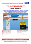
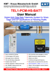
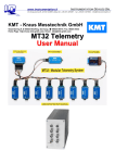
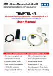
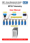
Telemetrie-Messtechnik Schnorrenberg User Manual MTP Multi channel telemetry system for rotating application, full software programmable with 16 bit resolution INSTRUCTIONS FOR QUALIFIED PERSONNEL ONLY! 2 to 64 channel Signal bandwidth 0-24000Hz Inputs for STG, TH-K, ICP or VOLT STG - Auto Zero calibration 4V bridge Excitation Gain 125-250-500-1000-2000 16 bit ADC, simultaneous sampling Full software programmable Inductive or battery power Rugged housing, water protected Output analog +/- 10V Digital data interface to PC Safety notes The device should only applied by instructed personnel. The power head emits strong magnetic radiation at 30-60 kHz to a distance of 300 mm. Therefore persons with cardiac pacemakers should not work with this device! Magnetic data storage media should be kept in a distance of at least 3m from the power head to avoid data loss. The same is valid for electromagnetic sensitive parts, devices and systems. Do not place the power head in the switched-on state on metallic objects, because this results in eddy currents which could overload the device and strong heat up small objects. Also the probe could be destroyed! No metallic objects, other than the disc-type coil, should be located in the air gap of the power head. The same applies to metallic parts within a radius of up to 50 mm in all directions. Do not use damaged or faulty cables! Never touch in the area between shaft and inductive head, the rotating shaft itself or rotor electronic contacts during operation! This is a “Class A” system suitable for operation in a laboratory or industrial environment. The system can cause electromagnetic interferences when used in residential areas or environments. In this case the operator is responsible for establishing protective procedures. Version 2014-05 2 Technical Data are subject to change without notice! Short description: The MTP telemetry is a small and flexible telemetry system for rotating applications. Each sensor module (2-channel) is equipped with signal conditioning, anti-aliasing filters, analog-to-digital converters and a digital output. All these up to 32 modules (=64 channels) will controlled by MTP-Controller module. By this concept it’s possible to install the acquisition modules close to the sensor to have short connections for the analog sensor lines. This avoids an undesired coupling of disturbances resulting in noisy signals. The interference insensiti ve digital outputs then can lead over wider distances of up to 25cm module to module. The MTP-Controller output is a PCM bit stream signal which can be modulated for emission by a transmitter module for distances of up to 0.1 with inductive telemetry transmission or up to 10m with radio telemetry transmission. Suitable for wireless data transmission rates of 312.5kbit/s up to 5000kbit/s MTP acquisition modules (rotor side) MTP-STG-V3 Acquisition module for 2 strain gages Full, half and quarter bridge (≥350) Fixed excitation 4V DC Offset calibration by auto zero Manual offset shifting after auto zero Gain: 125-250-500-1000-2000 Test shunt-cal step Signal bandwidth 0Hz to 24000Hz* MTP-VOLT-V3 Acquisition module for 2x high level inputs Range: ±0,625V, ± 1,25V, ±2,5V, ± 5V, ±10V Signal bandwidth 0Hz to 24000Hz* (*see table of cut-off-frequency) +4V sensor excitation max. 20mA Resolution 16bit Accuracy <0.2% Powering: 6.5-9V DC Current consumption 60mA Vibration: 5g Static acceleration: 3000g Shock: 10000g (*see table of cut-off-frequency) Resolution 16bit Accuracy <0.2% Powering: 6.5-9V DC Current consumption with full bridge 350 ohm 75mA Vibration: 5g Static acceleration: 3000g Shock: 10000g 80 x 34 x 14 mm Weight 60 grams 80 x 34 x 14 mm Weight 60 grams ® MTP-ICP Acquisition module for 2 ICP sensors Current EXC. 4mA Gain: 1-2-4-8-16-32 Signal bandwidth 3 Hz to 24000Hz* MTP-TH-K Acquisition module for 2x TH-K Inputs galvanic isolated Range -50 to 1000°C, -50 to 500°C or -50 to 250°C Cut-off filter 30Hz (more on request) Resolution 16bit Accuracy: 0.2% at 1000°C range Powering: 6.5-9V DC Current consumption 110mA Vibration: 5g Static acceleration: 3000g Shock: 10000g (*see table of cut-off-frequency) Resolution 16bit Accuracy <0.2% Powering: 6.5-9V DC Current consumption 100mA Vibration: 5g Static acceleration: 3000g Shock: 10000g 80 x 34 x 14 mm Weight 60 grams 80 x 34 x 14 mm Weight 60 grams MTP-CONTROL Controller 1- 32 acquisition modules Output: PCM Programmable via LAN adapter Powering: 6.5-9V DC Current consumption 40mA, with LANadapter 140mA Vibration: 5g Static acceleration: 3000g Shock: 10000g Additional environmental Operating Temperature -20 – +80°C Storage Temperature -30 – +90°C Humidity 100% 80 x 34 x 14 mm Weight 60 grams Cut off frequency from anti-aliasing filter (-3dB) and sampling rate (red) Bit rate 5000 kbit/s* 2500 kbit/s 1250 kbit/s 625 kbit/s 312,5 kbit/s 2 Channels ----24000 Hz max. (62500 Hz) 12000 Hz (31250 Hz) 6000 Hz (15625 Hz) 3000 Hz (7812.5 Hz) 4 Channels 8 Channels 16 Channels 32 Channels 64 Channels 24000 Hz max. (62500 Hz) 12000 Hz (31250 Hz) 6000 Hz (15625Hz) 3000 Hz (7812.5 Hz) 1500 Hz (3906.25 Hz) 12000 Hz (31250 Hz) 6000 Hz (15625 Hz) 3000 Hz (7812.5 Hz) 1500 Hz (3906.25 Hz) 750 Hz (1953.125 Hz) 6000 Hz (15625 Hz) 3000 Hz (7812.5 Hz) 1500 Hz (3906.25 Hz) 750 Hz (1953.125 Hz) 375 Hz (976.56 Hz) 3000 Hz (7812.5 Hz) 1500 Hz (3906.25 Hz) 750 Hz (1953.125 Hz) 375 Hz (976.56 Hz) 190 Hz (488.28 Hz) 1500 Hz (3906.25 Hz) 750 Hz (1953.125 Hz) 375 Hz (976.56 Hz) 190Hz (488.28 Hz) 95 Hz (244.14 Hz) For 4 Channels: 32 bit Barker Synch Code + 4x16 bit Data + 4x16 bit Data + 4x16 bit Data + 4x16 bit Data + 32 bit reserved For 8 Channels: 32 bit Barker Synch Code + 8x16 bit Data + 8x16 bit Data + 32 bit reserved For 16 Channels: 32 bit Barker Synch Code + 16x16 bit Data + 32 bit reserved For 32 Channels: 32 bit Barker Synch Code + 16x16 bit Data + 32 bit reserved (Frame Nr.1 = CH1..Ch16) + 32 bit Barker Synch Code + 16x16 bit Data + 32 bit reserved (Frame Nr.2 = CH17..Ch32) For 64 Channels: 32 bit Barker Synch Code + 16x16 bit Data + 32 bit reserved (Frame Nr.1 = CH1..Ch16) + 32 bit Barker Synch Code + 16x16 bit Data + 32 bit reserved (Frame Nr.2 = CH17..Ch32) + 32 bit Barker Synch Code + 16x16 bit Data + 32 bit reserved (Frame Nr.3 = CH33..Ch48) + 32 bit Barker Synch Code + 16x16 bit Data + 32 bit reserved (Frame Nr.4 = CH49..Ch64) *only with new radio telemetry, not with inductive telemetry! Version 2014-05 3 Technical Data are subject to change without notice! MTP-DEC8/16/32 Receiver unit for max 32 Channels output via 37 pol. Sub D (inductive transmission 45MHz version) Front side view Rear side view Female 37 pole Sub-D for analog signal output, CH 1 to 32 Out of function IND-Pickup head connection (at diversity option) Power ON LED Power Switch Active level LED of Pickup head Transmission error LED Fuse of powering defect LED Active level LED of Pickup head 7-pole female TUCHEL connector for power supply input (10–30V DC) IND-Pickup head connection Plug-side Optional BNC16/32 Box. Connect on 37pol Sub-D MTP –DEC8/16/24/32 System Parameters: Channel: 8,16 or 32x +/-10V analog outputs via Sub-D male socket Resolution: 16 bit D/A converter, with smoothing filter Power supply input: 10-30 VDC, power consumption <24 Watt Transmission: Digital PCM Bi-Phase Format – FSK, receiver Dimensions: 205 x 105 x 65mm Weight: 1.25 kg without cables and antenna Overall system accuracy between encoder input and decoder output: +/-0.25% without sensor influences Environmental Operating: -20 … +70°C Humidity: 20 ... 80% not condensing Vibration: 5g Static acceleration: 10g in all directions Shock: 100g in all directions Version 2014-05 4 Technical Data are subject to change without notice! MTP-DEC8/16/32 Receiver unit for max 32 Channels output via 37 pol. Sub D (radio transmission version with diversity receiver 320-1280kbit) Front side view Rear side view Female 37 pole Sub-D for analog signal output, CH 1 to 32 Out of function! Power Switch HF –Field strength display Transmission error LED Fuse of powering defect LED SMA antenna connector with active LED of antenna (diversity) 7-pole female TUCHEL connector for power supply input (10–30V DC) PCM out for IP-LAN-Interface (Opt.) (Option) Plug-side Optional BNC16/32 Box. Connect on 37pol Sub-D MTP –DEC8/16/24/32 System Parameters: Channel: 8,16 or 32x +/-10V analog outputs via Sub-D male socket Resolution: 16 bit D/A converter, with smoothing filter Power supply input: 10-30 VDC, power consumption <24 Watt Transmission: Digital PCM Bi-Phase Format – FSK, Dimensions: 205 x 105 x 65mm Weight: 1.25 kg without cables and antenna Overall system accuracy between encoder input and decoder output: +/-0.25% without sensor influences Environmental Operating: -20 … +70°C Humidity: 20 ... 80% not condensing Vibration: 5g Static acceleration: 10g in all directions Shock: 100g in all directions Version 2014-05 5 Technical Data are subject to change without notice! MTP-STG - Acquisition module for 2 channels strain gages (STG) MTP-STG-V3 Acquisition module for 2 strain gages Full, half and quarter bridge (≥350) Fixed excitation 4V DC Offset calibration by auto zero Manual offset shifting after auto zero Gain: 125-250-500-1000-2000 Test shunt-cal step (about 80% from measuring range at GAIN 2000) Signal bandwidth 0Hz to 24000Hz* (*see table of cut-off-frequency) STG connection for 2 channels Version 2014-05 Status LED ON = Error Resolution 16bit Accuracy <0.2% Powering: 6.5-9V DC Current consumption with full bridge 350 ohm 75mA Vibration: 5g Static acceleration: 3000g Shock: 10000g Gain and STG-Sensitivity (output +/-10V at decoder) Gain 125 = +/-20mV/V Gain 250 = +/-10mV/V Gain 500 = +/-5mV/V Gain 1000 = +/-2.50mV/V Gain 2000 = +/-1,25mV/V Powering and digital bus I/O 6 Technical Data are subject to change without notice! MTP-VOLT - Acquisition module for 2 channels high level inputs MTP-VOLT-V3 Acquisition module for 2x high level inputs Range: ±0,625V, ± 1,25V, ±2,5V, ± 5V, ±10V Signal bandwidth 0Hz to 24000Hz* (*see table of cut-off-frequency) Add. +4V sensor excitation max. 20mA Resolution 16bit Accuracy <0.2% Powering: 6.5-9V DC Current consumption 60mA Vibration: 5g Static acceleration: 3000g Shock: 10000g VOLT connection for 2 channels Status LED ON = Error Powering and digital bus I/O Shield only for noisy environmental (GND) Version 2014-05 7 Technical Data are subject to change without notice! MTP-ICP - Acquisition module for 2 channels ICP sensor ® MTP-ICP Acquisition module for 2 ICP sensors Current EXC. 4mA Gain: 1-2-4-8-16-32 Signal bandwidth 3 Hz to 24000Hz* (*see table of cut-off-frequency) Resolution 16bit Accuracy <0.2% Powering: 6.5-9V DC Current consumption 100mA Vibration: 5g Static acceleration: 3000g Shock: 10000g ICP connection for 2 channels Status LED ON = Error Powering and digital bus I/O GND only for optional cable shield! Shield only for noisy environmental (GND) Version 2014-05 8 Technical Data are subject to change without notice! MTP-TH-K - Acquisition module for 2 channels thermo couples MTP-TH-K Acquisition module for 2x TH-K Inputs galvanic isolated Range -50 to 1000°C, -50 to 500°C or -50 to 250°C Cut-off filter 30Hz (standard) more on request Resolution 16bit Accuracy: 0.2% at 1000°C range Powering: 6.5-9V DC Current consumption 110mA with cold junction compensation plate Vibration: 5g Static acceleration: 3000g Shock: 10000g TH-K compensation plate connection for 2 channels Status LED ON = Error Powering and digital bus I/O TH-K pin assignment Cold junction compensation plate is adjusted with MTP-TH-K module! Serial no. of plate must be the same as MTP-TH-K module! (fine adjustment) Cold junction compensation plate integrated in TH-K mini connector! Caution: Cablel length between MTP-TH-K module and compensation plate can be max. 100cm, factory standard length is 20cm! Shield cable, shield must connect on GND!! Version 2014-05 9 Technical Data are subject to change without notice! MTP-TH-K - Temperature range table Temperature measuring range type K: -50°C to +1000°C Temperature [°C] Output [V] Temperature [°C] Output [V] Temperature [°C] Output [V] Temperature [°C] Output [V] -50 -0.50 250 2.50 550 5.50 850 8.50 0 0.00 300 3.00 600 6.00 900 9.00 50 0.50 350 3.50 650 6.50 950 9.50 100 1.00 400 4.00 700 7.00 1000 10.00 150 1.50 450 4.50 750 7.50 200 2.00 500 5.00 800 8.00 Temperature measuring range type K: -50°C to +500°C Temperature [°C] Output [V] Temperature [°C] Output [V] Temperature [°C] Output [V] Temperature [°C] Output [V] -50 -1.00 100 2.00 250 5.00 400 8.00 0 0.00 150 3.00 300 6.00 450 9.00 50 1.00 200 4.00 350 7.00 500 10.00 Temperature [°C] Output [V] Temperature [°C] Output [V] Temperature measuring range type K: -50°C to +250°C Temperature [°C] Output [V] Temperature [°C] Output [V] -50 -2.00 150 6.00 0 0.00 200 8.00 50 2.00 250 10.00 100 4.00 If no thermocouple is connected or the connection broken, the output is -10V! Version 2014-05 10 Technical Data are subject to change without notice! MTP-CONTROLLER - Controller for 1- 32 acquisition modules = 64 channels MTP-CONTROL Controller for 1- 32 acquisition modules = 64 channels Output: PCM Programmable via LAN adapter Powering: 6.5-9V DC Current consumption 40mA (with connected LAN Adapter80mA) Vibration: 5g Static acceleration: 3000g Shock: 10000g Powering and Connection for radio or inductive transmitter digital bus I/O LAN-Adapter Connection Powering Control pin assignment +6.5-9V Example of a MTP system (rotating side) with LAN-Adapter and inductive transmitter incl. demo coil Version 2014-05 11 Technical Data are subject to change without notice! MTP - Block diagram example for 32 channels Version 2014-05 12 Technical Data are subject to change without notice! MTP – 24 CH cable loom and connection Take care with your pin connection if you solder the cable! - Don’t plug any modules if Power is ON!!! First power OFF!! Version 2014-05 13 Technical Data are subject to change without notice! MTP –picture of 24 CH cable loom with 12xMTP-STG modules, IND-HF Tx and IND-PWR Version 2014-05 14 Technical Data are subject to change without notice! MTP – 16 CH cable loom and connection Take care with your pin connection if you solder the cable! - Don’t plug any modules if Power is ON!!! First power OFF!! Version 2014-05 15 Technical Data are subject to change without notice! MTP –picture of 16 CH cable loom with 6xMTP-STG modules, IND-HF Tx and IND-PWR Version 2014-05 16 Technical Data are subject to change without notice! MTP – 8 CH cable loom and connection Take care with your pin connection if you solder the cable! - Don’t plug any modules if Power is ON!!! First power OFF!! Version 2014-05 17 Technical Data are subject to change without notice! MTP – 4 CH cable loom and connection Take care with your pin connection if you solder the cable! - Don’t plug any modules if Power is ON!!! First power OFF!! Version 2014-05 18 Technical Data are subject to change without notice! MTP- Explanation of abbreviations of block diagram NSYNC+ : ADC synchronizing signal+ NSYNC- : ADC synchronizing signal- ADCLK+ : ADC clock signal+ ADCLK- : ADC clock signal- SCLK+ : ADC data shift out clock signal+ SCLK- : ADC data shift out clock signal- SCL : IIC clock signal for setting up analog channel parameter SDA : IIC data signal for setting up analog channel parameter DC OUT/RDY : daisy chain signal out from controller while setting up analog channels / ready signal from the ADC while measuring DC2 .. DC16 : daisy chain signal from one module to the next module DC I : daisy chain signal to the controller from the end of the module chain DATA 2 .. DATA 8 : data daisy chain signals of the first analog block DATA 10 .. DATA 16: data daisy chain signals of the second analog block DATA 1 : data in from the first analog block DATA 9 : data In from the second analog block PCM : PCM output signal TX : RS232 transmit signal to the LAN adapter RX : RS232 receive signal from the LAN adapter +5V : +5V power for the LAN Adapter and the transmitter GND : power ground for the LAN Adapter and the transmitter PWR + : power supply + 6-9V PWR GND : power supply ground Important: In one analog block maximal 8 analog modules can be daisy chained. The daisy chain loops must not be broken! If one of the modules is missing, the signals of this position must be shorted together: "DATA OUT" <--> "DATA IN" and "DC OUT" <--> "DC IN" Version 2014-05 19 Technical Data are subject to change without notice! MTP acquisition module - dimensions Weight about 60 grams Version 2014-05 20 Technical Data are subject to change without notice! MTP Software setup via LAN-Adapter and notebook Power IN 6.5-9V DC 1) Power the MTP modules with power 6.5-9VDC 2) Connect the LAN-Adapter with the MTP-CONTROL module (see pin connection at MTP-CONTROL) 3) Adjust your notebook to manual on e.g. IP 192.168.0.20 4) Connect LAN-Adapter with your notebook via cross-over LAN cable 5) Open Microsoft Internet Browser and enter IP address 192.168.0.110 of LAN-Adapter 6) Now you get access on the web-interface and can adjust the MTP-CONTROL module Version 2014-05 21 Technical Data are subject to change without notice! MTP-CONTROL V3 - Software setup DOWNLOAD parameters for device First you can download the stored parameters from the acquisition modules via LAN adapter from the controller module . All connected acquisition modules will detect! Caution: Never use the refresh button Version 2014-05 on your browser; otherwise the parameters of you browser cash will upload to the MTP-STG!° 22 Technical Data are subject to change without notice! BRIDGE setting STG Select full-, half- or quarter-bridge by popup window Execute through “Upload Parameters to MT-PRO and perform Autozero” button If you want test your bridge, you can execute the function Test-Shunt Resistor for 20 sec. button In this case all STG channels get a shunt-cal step of about 80% of the from measuring range at GAIN 2000 In this case all STG channels get a shunt-cal step of about 40% of the from measuring range at GAIN 1000 In this case all STG channels get a shunt-cal step of about 20% of the from measuring range at GAIN 500 In this case all STG channels get a shunt-cal step of about 10% of the from measuring range at GAIN 250 In this case all STG channels get a shunt-cal step of about 5% of the from measuring range at GAIN 125 Version 2014-05 23 Technical Data are subject to change without notice! GAIN setting STG Select gain of 125-250-500-1000 or 2000 by popup window After change the gain you must make a new autozero!! Execute through “Upload Parameters to MT-PRO and perform Autozero” button Version 2014-05 24 Technical Data are subject to change without notice! AutoZero setting STG Select Auto-Zero per channel. The Auto-Zero function will be executed only one time per upload the parameters to MTP-STG! It will be stored also after power off in the MTP-STG until you make a new Auto-Zero on this channel! Execute through “Upload Parameters to MT-PRO and perform Autozero” button Version 2014-05 25 Technical Data are subject to change without notice! Manual Offset shifting after AutoZero After AutoZero you can shift (if necessary) the offset in +/-2000 steps Execute through “Upload Parameters to MT-PRO and perform Autozero” button Version 2014-05 26 Technical Data are subject to change without notice! Inductive transmission (2500kbit) with MTP-IND-TX-RX with 45MHz carrier! With 45MHz carrier is only 1x winding necessary! Attach for electromagnetic insulation “Ferrite Tape” 2 x one layer around the shaft. Make transmitting coil with 1x winding and twisted the end of wire. Use CUL 0.63-1.00mm wire (CUL = Enamelled copper wire) Fixed it with 3 layers mounting tape Extend the CUL wire flexible 0.14-0.25mm wire (to decouple the inflexible 1mm wire!, at 0.63 not necessary) Twisted also the flexible wire and solder it on the MTPIND-Tx (isolate all solder points with shrink tubing) Version 2014-05 27 Technical Data are subject to change without notice! MTP-IND-TX-RX with 45MHz carrier! Pickup head (2500kbit) Inductive Pick-Up head mount in this position! Distance between head and Tx coil can be up to 100mm Typical 50mm, distance deepens of application!! To avoid transmitting problems, the transmitter module must be close the transmitting antenna! The cables (PCM/GND/+5V) between MPT-IND-TX 45MHz and MTP-CONTROL can be 1000mm long! CAUTION: If you want to install also an inductive power coil close to the data coil, the minimal distance must be <10mm! (distance between IND-PWR coil to IND-DATA coil) Version 2014-05 28 Technical Data are subject to change without notice! KMT - Kraus Messtechnik GmbH Gewerbering 9, D-83624 Otterfing, Germany, 08024-48737, Fax. 08024-5532 Home Page: http://www.kmt-telemetry.com, Email: [email protected] Konformitätserklärung Declaration of Conformity Declaration de Conformité Wir We Nous KMT - Kraus Messtechnik GmbH Anschrift Address Adress Gewerbering 9, D-83624 Otterfing, Germany erklären in alleiniger Verantwortung, daß das Produkt declare under our sole responsibility, that the product declarons sous notre seule responsibilité, que le produit Bezeichnung Name Nom Messdatenübertragungssystem Typ,Modell,Artikel-Nr., Größe Type,Model, Article No.,Taille Type, Modèle, Mo.d'Article,Taille MTP Modular Telemetry Pro mit den Anforderungen der Normen und Richtlinien fulfills the requirements of the standard and regulations of the Directive satisfait aux exigences des normes et directives 108/2004/EG Elektromagnetische Verträglichkeit EMV / EMC DIN EN 61000-6-3 Ausgabe 2002-8 Elektromagnetische Verträglichkeit EMV Teil 6-3 Fachgrundnorm Störaussendung DIN EN 61000-6-1 Ausgabe 2002-8 Elektromagnetische Verträglichkeit EMV Teil 6-1 Fachgrundnorm Störfestigkeit und den angezogenen Prüfberichten übereinstimmt und damit den Bestimmungen entspricht. and the taken test reports und therefore corresponds to the regulations of the Directive et les rapports d'essais notifiés et, ainsi, correspond aux règlement de la Directive. Otterfing, 04.06.2012 Martin Kraus Ort und Datum der Ausstellung Place and Date of Issua Lieu et date d'établissement Name und Unterschrift des Befugten Name and Signature of authorized person Nom et signature de la personne autorisée Version 2014-05 29 Technical Data are subject to change without notice! KMT - Kraus Messtechnik GmbH Gewerbering 9, D-83624 Otterfing, Germany, 08024-48737, Fax. 08024-5532 Home Page: http://www.kmt-telemetry.com, Email: [email protected] MT P INDUCTIVE POWER XL, XXL and XXXL with flat COIL User Manual Inductive power supply set Power supply for power head 25 and 50mm mounting tape to fix coil on shaft Ferrite tape 30mmx3m CUL 1.00 mm (Enamelled copper wire) DC Power cable Optional AC/DC Adapter 120Watt (24V 5A) IND-PWR AC/DC module Input: AC from coil Output 6.5VDC, 1000-2400mA Power Head with 5m cable Picture shows standard Inductive Power Supply for diameter up to 300mm INSTRUCTIONS FOR QUALIFIED PERSONNEL ONLY! Version 2014-05 30 Technical Data are subject to change without notice! Safety notes for inductive powering The device should only applied by instructed personnel. The power head emits strong magnetic radiation at 30-60 kHz to a distance of 300 mm. Therefore persons with cardiac pacemakers should not work with this device! Magnetic data storage media should be kept in a distance of at least 3m from the power head to avoid data loss. The same is valid for electromagnetic sensitive parts, devices and systems. Do not place the power head in the switched-on state on metallic objects, because this results in eddy currents which could overload the device and strong heat up small objects. Also the probe could be destroyed! No metallic objects, other than the disc-type coil, should be located in the air gap of the power head. The same applies to metallic parts within a radius of up to 50 mm in all directions. Do not use damaged or faulty cables! Never touch in the area between shaft and inductive head, the rotating shaft itself or rotor electronic contacts during operation! This is a “Class A” system suitable for operation in a laboratory or industrial environment. The system can cause electromagnetic interferences when used in residential areas or environments. In this case the operator is responsible for establishing protective procedures. Version 2014-05 31 Technical Data are subject to change without notice! MTP-IND-PWR - AC/DC Module for inductive power MTP-IND-PWR AC/DC Module for inductive power Input: 30-60kHz 10-60V AC Can also power with DC 12-24V (Input on COIL / COIL) Output: 6.5 DC Current: up to 2400mA Weight: 60 gram Vibration: 5g Shock: 3000g IND- PWR COIL AC IN - 30-60kHz 6.5V DC OUT Control pin assignment IND- PWR COIL AC INPUT - 30-60kHz Version 2014-05 IND- PWR 6.5V DC OUTPUT 32 Technical Data are subject to change without notice! MTP module housing - dimensions Weight about 60 grams Version 2014-05 33 Technical Data are subject to change without notice! MTP-inductive power supply Installation of coil for inductive powering on shaft Attach for electromagnetic isolation “Ferrite Tape” 2x parallel and 1x in the middle over two layer around the shaft Strip the isolation from the end of the wire with a skinning tool or head up you soldering iron over 450°C to burn off the insulation from the wire! Make power coil with 3-18 windings for 1000-20mm diameter (see diagram) and twisted the end of wire. Use 0.63…1.00 mm (1.00mm for diameter of 100-1000mm) CUL wire (Enamelled copper wire) Version 2014-05 34 Technical Data are subject to change without notice! Solder the end of the wire on the AC IN of the IND-PWR module and isolate all solder points with shrink tubing. Fixed with 3 layers mounting tape Note: “The inductive load of the MTP- IND-PWR and the capacitor in the Power Head must be in resonance to get the optimal transmission. The inductive load of the shaft depends of diameters, material and number of windings! Control the output voltage and move the power-head in the max distance to the coil. The output voltage must be 6.5 V! The pins “Coil” are the AC power input from the coil. On the pins “+6.5” and “GND“ you get a stabilized output voltage of 6.5V DC. The max. load current on the DC output is 2400mA. The IND-PWR converter will use instead battery pack! Never use any battery together with the MTP-IndPwr! You should mount the power head at a fixed location that it’s as free as possible from vibration influences. 6.5 DC OUT max. 2400mA Version 2014-05 The center of the coil should be in the same horizontal position as the center of the power head. The distance is optimal in the range between 5 and 10mm. (depends of shaft and current consumption) AC IN 35 Technical Data are subject to change without notice! Find the correct amount of windings of inductive power coil Optimum windings for steel shafts 1200 Diameter mm 1000 800 600 400 200 0 0 5 10 15 20 Windings Windings Diameter (mm) 3 1000 5 490 7 290 9 190 10 150 12 120 14 80 16 45 18 20 Distance 5-15mm Magnetic field Distance dependent of current consumption e.g. 2000mA at 5-10mm, 500mA at 10-15mm Version 2014-05 36 Technical Data are subject to change without notice! Recommend power heads: Diameter: 4 - Channel 8 - Channel 16 - Channel 150mm XL XL XL 300mm XL XL XXL 500mm XL XXL XXXL 1000mm XXL XXXL XXXL 32 - Channel XXL XXXL XXXL On request IND-PWR-HEAD-XL and XXL IND-PWR-HEAD-XXXL Caution for use of XXL and XXXL power heads! Cable must unrolled for use, otherwise it will warm up! Version 2014-05 37 Technical Data are subject to change without notice! Dimensions of IND-PWR-HEAD- XL and XXL Version 2014-05 38 Technical Data are subject to change without notice! Dimensions of IND-PWR-HEAD-XXXL Version 2014-05 39 Technical Data are subject to change without notice! MTP-IND-PWR Following must be considered at the mounting of the inductive power head Shaft with Cu wire Coil Magnetic field 25-30mm Don’t use for mounting any kind metal in this area (25-30mm)! Otherwise magnetic energy will flow in the metal and decrease the distance between power head and coil (on shaft)! Example of mounting Wrong!!! Mounting (only if metal) plate cover the active area of inductive head Version 2014-05 40 Technical Data are subject to change without notice! IND-Power generator for L, XL, XXL and XXXL Powerhead Technical data Power output: AC 25-35kHz for power head L, XL, XXL and XXXL Power input: 10-30 V DC, typical 24V Power consumption <100 Watt, deepens of power head Dimensions: 205 x 105 x 65mm Weight: 1.275 kg Environmental Operating: -20 … +70°C Humidity: 20 ... 80% not condensing Vibration: 5g Mil Standard Static acceleration: 10g in all directions Shock: 50g in all directions Version 2014-05 41 Technical Data are subject to change without notice! MTP-IND-PWR-XXL Pin connection CONTROL - Not used! DC 10-30V typical 24V (up to 100 WATT* AC 25-35kHz output power head * deepens of power head) E= have no function Powering and AC out LED flashing = auto adjustment LED ON = finish ON= Inductive resonance freq. of power head reached! Can take up to 20sec.! Control out of function Power control LED Power Switch AC 25-35kHz output for power head Power INPUT DC 10-30V typical 24V (up to 100WATT*) Version 2014-05 42 Technical Data are subject to change without notice! KMT - Kraus Messtechnik GmbH Gewerbering 9, D-83624 Otterfing, Germany, 08024-48737, Fax. 08024-5532 Home Page http://www.kmt-telemetry.com, Email: [email protected] MT P INDUCTIVE POWER with RING COIL User Manual Inductive power supply set AC/DC Adapter 120Watt (24V 5A) (Option) DC power cable Power supply for power head Inductive ring coil IND-PWR AC/DC module Input: AC from coil Output 5VDC max. 1000mA Power Head with 5m cable (optional longer cable up to 25m) CUL 0.63 mm for IND-PWR coil and IND-DATA coil (Enamelled copper wire) INSTRUCTIONS FOR QUALIFIED PERSONNEL ONLY! Version 2014-05 43 Technical Data are subject to change without notice! Safety notes for inductive powering The device should only applied by instructed personnel. The power head emits strong magnetic radiation at 30-60 kHz to a distance of 300 mm. Therefore persons with cardiac pacemakers should not work with this device! Magnetic data storage media should be kept in a distance of at least 3m from the power head to avoid data loss. The same is valid for electromagnetic sensitive parts, devices and systems. Do not place the power head in the switched-on state on metallic objects, because this results in eddy currents which could overload the device and strong heat up small objects. Also the probe could be destroyed! No metallic objects, other than the disc-type coil, should be located in the air gap of the power head. The same applies to metallic parts within a radius of up to 50 mm in all directions. Do not use damaged or faulty cables! Never touch in the area between shaft and inductive head, the rotating shaft itself or rotor electronic contacts during operation! This is a “Class A” system suitable for operation in a laboratory or industrial environment. The system can cause electromagnetic interferences when used in residential areas or environments. In this case the operator is responsible for establishing protective procedures. Version 2014-05 44 Technical Data are subject to change without notice! MTP-IND-PWR - AC/DC Module for inductive power MTP-IND-PWR AC/DC Module for inductive power Input: 30-60kHz 10-60V AC Can also power with DC 12-24V (Input on COIL / COIL) Output: 6.5 DC Current: up to 2400mA Weight: 60 gram Vibration: 5g Shock: 3000g IND- PWR COIL AC IN - 30-60kHz 6.5V DC OUT Control pin assignment IND- PWR COIL AC INPUT - 30-60kHz Version 2014-05 IND- PWR 6.5V DC OUTPUT 45 Technical Data are subject to change without notice! MTP-IND-PWR housing - dimensions Weight about 60 grams Version 2014-05 46 Technical Data are subject to change without notice! Inductive power supply RING COIL - Distance power head and pickup head Solder pins for power coil and wire to IND-PWR 5V Please use twisted wire If you use longer wires >100mm, please use shied and twisted wire e.g. LAN cable CAT 7 ! IND-Data Pickup Distance to coil typical 5-50mm In ideal case upto 100mm IND-PWR Head Distance to coil 5-30 mm CUL 0.63 mm for IND-DATA coil - 1 winding CUL 0.63 mm for IND-PWR coil - 5 winding (Enamelled copper wire) IND-Data Pickup Distance to coil +/-50mm IND-Data Pickup Distance to coil +/-50mm Solder pins for data coil and wire to IND-TX 45MHz Please use twisted wire If you use longer wires >100mm, please use shied and twisted wire e.g. LAN cable CAT 7 ! max. 1000mm recommend (only shielded!) Data cable CAT. 7A S/FTP 4P AWG22 (= solid bare copper wire 0.64mm-diameter) recommend or Data cable CAT. 7 S/FTP 4P AWG23 (= solid bare copper wire 0.55mm-diameter) Version 2014-05 47 Technical Data are subject to change without notice! RING COIL – uncouple the 45MHz frequency from inductive data coil with ferrite core filter to reach better transmitting range! Remove the aluminum foil under the ferrite core! You can use also one little large ferrite core and make 1-2 loops with the twisted pair cable through the core! Good results!! Version 2014-05 48 Technical Data are subject to change without notice! Inductive power supply RING COIL – wire connection We recommend to fix the wire of coil with some epoxy resin (data & power coil) Use shrink tubing Direct behind the solder pins the data wire must be twisted, otherwise you can get data transmission problems! Best cover wire with aluminum foil Good Avoid this bad wiring! Here you can get transmission problems! Bad Version 2014-05 49 Technical Data are subject to change without notice! Inductive power supply RING COIL – Distance power head PWR-COIL 5 winding with CUL wire 0.63mm DATA-COIL 1 winding with CUL wire 0.63mm (Enamelled copper wire) (Enamelled copper wire) Distance 5-30mm Distance +/-9mm Version 2014-05 50 Technical Data are subject to change without notice! Inductive power supply Example of a RING COIL with inner diameter 191mm Version 2014-05 51 Technical Data are subject to change without notice! Dimensions of IND-PWR-HEAD-XXL Version 2014-05 52 Technical Data are subject to change without notice! Dimensions of IND-PWR-HEAD-XXL Version 2014-05 53 Technical Data are subject to change without notice! IND-PWR-HEAD-XXL Caution for use of power heads! Cable must unrolled for use, otherwise it will warm up! Version 2014-05 54 Technical Data are subject to change without notice!