1
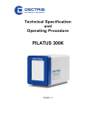
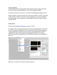
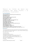
USER MANUAL
PILATUS Detector Systems
Version 1.2
Table of Contents
1
Document History .....................................................................................4
1.1
Changes ............................................................................................4
2 How to use this manual.............................................................................5
2.1
Address and support..........................................................................5
2.2
Explanation of symbols......................................................................5
2.3
Definitions of terms ............................................................................6
3 Warnings...................................................................................................7
4 System Description...................................................................................8
4.1
Overview............................................................................................8
4.2
Principle.............................................................................................8
5 Software..................................................................................................11
5.1.1
Overview of TVX.......................................................................12
5.1.2
Overview of Camserver ............................................................13
6 Getting started ........................................................................................13
7 How to operate the system .....................................................................14
7.1
Login to the computer ......................................................................14
7.2
Connect to a network.......................................................................14
8 How to use TVX......................................................................................16
8.1
Description of the directories ...........................................................16
8.2
Main commands ..............................................................................17
8.3
Description of the image display......................................................21
8.4
Image formats..................................................................................25
8.5
Analysis commands.........................................................................25
8.6
Mask files.........................................................................................27
8.7
User defined commands..................................................................28
8.8
Glossary files ...................................................................................29
8.9
Various commands ..........................................................................29
9 How to use Camserver ...........................................................................30
9.1
Main commands ..............................................................................30
9.2
Variables..........................................................................................31
9.3
Exposure series...............................................................................32
9.4
Integration into other systems..........................................................32
9.4.1
Steps to bring up a PILATUS detector in a new environment:..33
10
Calibrating the detector .......................................................................36
10.1 Principle...........................................................................................36
10.2 Calibrating the detector manually ....................................................37
10.3 Loading trim files manually ..............................................................41
10.4 Adjusting the threshold level manually.............................................42
10.5 Adjusting the analog amplifier manually ..........................................43
10.6 Loading trim files and setting the threshold automatically................45
11
Creating a flat field correction image...................................................47
11.1 Using the flat field correction image.................................................48
12
Factory Calibration and Correction......................................................49
13
External Triggering ..............................................................................51
13.1 Command list...................................................................................51
13.2 External Trigger mode .....................................................................52
I
13.3 External Multi Trigger mode.............................................................54
13.4 External Enable mode .....................................................................54
13.5 Multiple Exposure mode ..................................................................56
14
Appendix .............................................................................................57
14.1 Table of figures................................................................................57
II
1 Document History
Actual document
Version
Date
status
prepared
1.2
6.2.2009
In Work
PS
checked
released
1.1 Changes
Version
1.1
1.2
Date
31.08.2007
06.02.2009
Changes
Various improvements
Various improvements
User_Manual-PILATUS-V1_2.doc
4/57
2 How to use this manual
Before you start to operate the PILATUS detector system please read this
manual thoroughly.
This user manual has been especially designed for DECTRIS PILATUS
detector systems.
The technical specification of the detector system is also part of this user
manual. Read it thoroughly.
2.1 Address and support
DECTRIS Ltd.
Neuenhoferstrasse 107
Switzerland
Phone: +41 56 500 21 00
Fax: + 41 56 500 21 01
Email: [email protected]
Should you have questions concerning the system or its use, please contact
us via phone, mail or fax.
2.2 Explanation of symbols
Symbol
Description
Important or helpful notice
Caution. Please follow the instruction carefully to prevent
equipment damage or personal injury.
DC-current
AC-current
Ground
User_Manual-PILATUS-V1_2.doc
5/57
2.3 Definitions of terms
Term
MCB
DCB
BCB
DAC
Description
Module control board
Detector control board
Bank control board
Digital to Analog Converter
User_Manual-PILATUS-V1_2.doc
6/57
3 Warnings
Please read these warnings before operating the detector
•
•
•
•
•
•
•
•
•
•
•
•
Before turning the power supply on, check the supply voltage with the
label on the power supply. Using the improper mains voltage will
destroy the power supply and damage the detector.
Power down the detector system before connecting or disconnecting
any cable.
Make sure the cables are connected and properly secured.
Avoid pressure or tension on the cables.
The air intakes and outlet for the detector fan should not be obstructed.
The detector system should have enough space for proper ventilation.
Operating the detector outside the specified ambient conditions could
damage the system
Do not touch the entrance window of the detector.
The detector is not specified to withstand direct beam at a synchrotron.
Such exposure will damage the exposed pixels.
Replace the protective cover when the detector is not in use.
On powering up the detector, the ammeter on the power supply should
show a current of approximately 2 A. In operation the ammeter should
not exceed a current of about 3 A. (where applicable)
With any over-current condition, immediately shut the detector down
and restart it.
Opening the detector or the power supply housing without the explicit
instructions from DECTRIS will void the warranty.
The Linux-OS on the PC has a customized Kernel to improve data
throughput.
DO NOT UPDATE THE OS OR THE KERNEL
User_Manual-PILATUS-V1_2.doc
7/57
4 System Description
4.1 Overview
A PILATUS detector system consists of the following components:
• Detector
• Analysis PC with SuSE Linux, the data acquisition tool camserver and
the data analysis tool TVX
• Power supply (where applicable)
• Connecting cables
Data
PC
Detector PILATUS
Figure 1 Overview of the PILATUS detector system setup.
4.2 Principle
DECTRIS X-ray detector systems operate in "single photon counting" mode
and are based on the newly developed CMOS hybrid pixel technology. The
main difference with respect to existing detectors is that the x-rays are directly
transformed into electric charge (Figure 2) and processed in the CMOS
readout chips. This new design has no dark current or readout noise, a high
dynamic range of 1'000'000 (20 bits), a read out time of less than 3 ms, a
framing rate of over 200 images/s and an excellent point spread function of <
1 pixel. The quantum efficiency of the 0.32 mm thick silicon sensor is optimal
for experiments in the energy range from 3-12 keV; however the detectors can
be used for energies of up to 30keV or more. The counting rate is more than
2x10⁶/s/pixel, enough to perform many experiments using the high flux of
modern synchrotron light sources.
User_Manual-PILATUS-V1_2.doc
8/57
Figure 2 Principle of direct detection.
A DECTRIS hybrid pixel detector is composed of a silicon sensor, which is a
two-dimensional array of pn-diodes processed in high-resistivity silicon,
connected to an array of readout channels designed with advanced CMOS
technology (Figure 3). Each readout channel is connected to its corresponding
detecting element through a microscopic indium ball, with a typical diameter of
18 um. This connection process is called ‘bump-bonding’.
Figure 3 The detector module, the basic element of all DECTRIS detector systems
User_Manual-PILATUS-V1_2.doc
9/57
The great advantage of this approach is that standard technologies are used
for both the silicon sensor and the CMOS readout chips, which guarantees
highest quality. Both processes are optimized separately, as the best silicon
substrates for X-ray detection and for high-speed/high-quality electronics are
very different. Moreover, the small size of the pixel and of the interconnection
results in a very low capacitance, which has the beneficial effect of reducing
the noise and power consumption of the pixel readout electronics.
X-ray data collection can be improved with detectors operating in single
photon counting mode. A hybrid pixel which features single photon counting
comprises a preamplifier, which amplifies the charge generated in the sensor
by the incoming X-ray, and a discriminator, which produces a digital signal if
the incoming charge exceeds a pre-defined threshold. The discriminator feeds
a 20 bit counter, which then leads to completely digital storage and noiseless
readout of the number of detected X-rays in each pixel (Figure 4)
PILATUS II Pixel Cell
Pixsel
6 Bit Latch
+ DAC
Global
Tresh
Bump
Pad
Comp
+
Pixsel
Pulse
Shaper
CNT/RO
φ1- φ2
Gen
CS
Amp
20 bit
Counter
Pixsel
Pixsel
1.6fF
Pixsel
CAL
Rowsel
AOUT ENA DCLK
DIN
Colsel
&
Pixsel
DOUT
Figure 4 Block diagramm of the CMOS chip
The fundamental unit of the DECTRIS detectors consists of a single fully
depleted monolithic silicon sensor with an 8 x 2 array of CMOS readout chips
bump-bonded to it. Each sensor is a continuous array of 487 x 197 = 94965
pixels without dead areas and covers an active area of 83.8 x 33.5 mm2. The
readout chips are wire-bonded to the mounting bracket with its readout control
electronics and forms the complete module (Figure 3).
User_Manual-PILATUS-V1_2.doc
10/57
5 Software
The operating software for the PILATUS detector system consists of two
software components:
•
TVX
Data acquisition control and data analysis software
•
Camserver
Operating software for the detector
Those two software packages are normally installed on one PC and
communicate with each other through an internal socket connection.
Figure 5 Normal operation with TVX and Camserver on one computer.
But it is also possible, to operate the detector without TVX and access
Camserver directly via a socket connection from another PC.
Figure 6 Operation with TVX and Camserver on separate computers.
User_Manual-PILATUS-V1_2.doc
11/57
5.1.1 Overview of TVX
TVX is a free, open source, data acquisition and control software suite tailored
to X-ray science. TVX is an attempt to provide a flexible user interface that is
easily adapted to control a broad range of 2-D X-ray detectors as well as a
powerful collection of analysis tools.
TVX operates by distributing the tasks of data analysis and hardware control
between two separate programs. The first program, which is most often
referred to as TVX, contains the user interface and analysis tool suite. The
other, which is referred to as the Camserver, is responsible for controlling the
hardware of the specific data acquisition system. These two programs
communicate over a TCP/IP connection, as shown in Figure 5, and thus do
not need to run on the same machine, or even under the same operating
system; see Figure 6.
Figure 7 TVX communication scheme
Camserver bundles all of the details of the hardware control into a C program
which can be ported across computer platforms. An added benefit of this
model is that it allows the experimenters to do their analysis wherever and
whenever it is most convenient from them, be it at the beam line while the
data are being taken or back at their home institution or corporation.
TVX compiles and operates both on Linux and Mac OS X systems.
Camserver, except the demo version, requires specific camera hardware for
operation.
Figure 8. TVX control and analysis layout schematic.
User_Manual-PILATUS-V1_2.doc
12/57
5.1.2 Overview of Camserver
Camserver is a freestanding program that controls an x-ray camera and
provides a simple user interface for "atomic" (single function) commands. It is
intended to provide a spartan, but fully functional, low level interface to
camera hardware.
On invocation, the program 'camserver' takes a single command-line
argument, the path to its resource file, by default called 'camrc'. Camserver
will also use the same path to open its debugging file, 'camdbg.out'.
A major function of camserver is to accept socket connections from a high
level controller (e.g., 'tvx'), which can provide high level services to this or
other cameras. The interface is a simple text-based message passing system.
Images - the ultimate product of a working area x-ray detector - do not pass
thru the socket interface, but are written to a configurable location (e.g., a nfs
mount) where any program can access them. See more on 9.4
6 Getting started
See the appropriate chapter in the technical specification of your detector
system.
User_Manual-PILATUS-V1_2.doc
13/57
7 How to operate the system
Before you turn on the system, make sure you have read this manual, the
technical specification and connected the detector accordingly.
7.1 Login to the computer
Turn on the PC.
Log in procedure:
User:
PW:
Root PW:
7.2 Connect to a network
The IP address of the detector is identical to the IP address of the PC where
Camserver is running on. In case TVX and Camserver are running on different
machines the IP address and hostname should be adjusted in the following
files:
/home/det/p2_det/tvxrc
/etc/hosts
See also 9.4 how to integrate the detector into other systems.
User_Manual-PILATUS-V1_2.doc
14/57
Figure 9 Shell showing the active path and the runtvx command.
Figure 10 Screen after runtvx has initialized the detector and opened the Camserver
and TVX window.
User_Manual-PILATUS-V1_2.doc
15/57
8 How to use TVX
8.1 Description of the directories
In the default setup, all data for the use of the PILATUS detector system is in
the directory /home/det/p2_det.
Figure 11 Relevant directories and folders.
Directory
Description
config
Glossary (.gl) files for the detector
correct
Detector specifications
docs
User manual, technical specification
graphs
Graphs are stored by default in this directory
images
Images are stored by default in this directory
programs
Program code for TVX and Camserver
User_Manual-PILATUS-V1_2.doc
16/57
8.2 Main commands
TVX is a powerful tool for data acquisition and analysis and has a complete
description of all commands, which can be accessed through the help
command.
This section describes only the most commonly used commands in TVX. All
commands are case-insensitive; however, filenames are case-sensitive.
An ‘object’ in TVX may be an image or a graph. Many commands, such as
move, will work on objects of either kind. Objects may combined with
standard arithmetic operators (+, -, *, /, +=, etc.), logical operators (<, >, <=,
>=, |, ||, &, &&) and special operators (<<, >>, !, :, <<=, etc.) in arbitrarily
complicated expressions to perform sophisticated analyses and to construct
custom scripts. In case of doubt, try it out you can’t hurt anything.
User_Manual-PILATUS-V1_2.doc
17/57
Figure 12 The ‘menu’ of TVX.
Many commands in TVX or Camserver require an input value or argument.
Without the declaration of a value, the currently set value is shown.
In this manual input values are shown in Italic.
User_Manual-PILATUS-V1_2.doc
18/57
Command or Macro
Description
menu
Shows all commands
It is divided in 4 parts:
• TVX reserved words
• TVX defined commands
• Macros, saved in default.gl or typed by the user
• Variables
help command -orman command
Shows the help text for the command. Help help is a
good way to start. Help “gr*” will show all commands
beginning with ‘gr’; the quotes are required, else the
system takes ‘*’ to mean multiplication.
ESC-button
Stop a running task and return to the TVX line
interpreter
CTRL-C
Full reset of TVX
cam k
stops the running Camserver processes
rbd
Read Back Detector.
Self test of the digital part of the detector. Sends a
digital pattern to each pixel, reads it out and displays
the image.
Use this command always after a startup.
Every pixel should show 1000 counts.
calibdet
Self test of the detector.
Sends 100 calibrate pulses to the analog part of the
detector, reads back the recorded values as an image
and displays the result. Every pixel should show 100
counts.
Use this command always after a startup.
Should the pixels not show 100 counts in the absence
of radiation, repeat the command. If the image is
black, type setdac, then repeat the command. In case
this tests fails, turn the power supply off, close the
TVX and Camserver windows and start up again.
setdac
Sets all Digital Analog Converters (DAC) to the
predefined values.
imagepath path
Image Path
Without the input of a path it displays the current
default path. With a declaration it changes the default
User_Manual-PILATUS-V1_2.doc
19/57
Command or Macro
Description
path for images. The imagepath command also sets
the autoname to the new path.
grafpath path
Display or change the default path for graphs. The
keyword 'grafpath' can be used in expressions as
[grafpath]
exp filename
Make an exposure. If filename is not given, TVX uses
the next automatic filename. The files created are
saved in the directory specified in imagepath.
expose exposure time
(in seconds)
expose 1: makes an image with an exposure time of 1
sec.
shortest exposure time: > 1 us, 0.000’001.
Shows the exposed image immediately on completion.
Exposem
exposure time
continuous camera mode without saving images.
Takes images until any key is pressed. The last image
is stored in temp.tif
disp filename
Display an image. Opens up to 3 windows for
successive invocations.
disp1 filename
Displays an image reusing the last window. Useful in
loops.
graf fn1[fn2[ fn3]]
Graph up to 3 graphs in a window
show variable -orshow string
Shows the content of a variable or a string
define
DEFINE name="instruction1; instruction2;....."
Defines user symbol name and value.
E.g. define tpict="zpict; move imt=im3" defines symbol
tpict as a comination of ‘zpict’, and the built-in move
instruction.
CaptureIM filename
Capture the default image to filename
captures a displayed image (and its zoom) as a .ppm
(portable pixmap) file, including coloration and
contrast adjustments.
CaptureGR filename
Capture the default graph to filename
Captures a displayed graph (and its zoom) as a .ppm
(portable pixmap) file.
connect [ip_address]
Connect the socket connection from TVX to the
Camserver at [ip_address]
disconnect
Disconnect the socket connection from TVX to
User_Manual-PILATUS-V1_2.doc
20/57
Command or Macro
Description
Camserver. E.g, so that a beamline operating system
like EPICS can take control over the Camserver.
8.3 Description of the image display
After an exposure, the image will be shown in a separate window, the image
window.
3 sliders to
control the
contrast and
the color
range:
low, high,
factor
Coordinate:
(0,0)
Coordinate:
(487,0)
Zoom factor
Selection
tool
Coordinate:
(487,195)
Color
scheme
Numerical values for the selection tool.
Actual position of the cursor and the intensitiy of the pixel
User_Manual-PILATUS-V1_2.doc
21/57
Display tools
Description
(sliders)
Define the color and the contrast of the image. For every
value of a pixel a color from a lookup table will be
displayed.
With the two left sliders the cut off for the low and high
values can be set. Values outside this range are displayed
with the same color.. The third slider defines the contrast
factor.
The sliders can be moved with the mouse or by putting the
mouse on the slider and adjust the value with the left and
right cursor buttons. They can also be set from the
command line using the disp command.
zoom
A magnification can be chosen and the enlarged area is
shown in a new window. The zoom outline in the main
window can be positioned by clicking or dragging with the
mouse with the right button depressed.
Selection tools
pointer
normal pointer
annulus
Allows analysis of circular areas.
The sizes of the circles can be adjusted with the mouse or
directly by the setting the values in the image window.
box
Allows analysis of rectangular areas. Move the box with
the right mouse button pushed or put the center of the box
with the left mouse button. The size of the box can be
adjusted with the mouse or directly by setting the values in
the image window.
butterfly
Allows analysis of special shaped areas.
The shape of the area can be adjusted with the mouse or
directly by the setting the values in the image window. The
circle is only for alignment purposes.
Line
Distance measuring tool. Requires that the correct pixel
size be set in detector setup file (name)
resolution
Resolution circles for crystallographic patterns. Calculates
the resolution of the image. The correct parameters for the
detector should be set in the detector setup file or from the
command line, (det_dist, lamdba and pixel size)
Display mode
greys
color lookup table with gray scale.
spectral
color lookup table with a spectral distribution (blue and
User_Manual-PILATUS-V1_2.doc
22/57
Display tools
Description
black near zero, red fading to pink and
white at the high end)
thermal
color lookup table going from blue through yellow and red,
but no greens
decades
The values between Min and Max are displayed linearly,
but with the scale wrapping around Scal number of time.
Thus, Scal = 1 is linear, Scal = 5 covers the range Min to
Max with 5 linear segments going from 0 to 255, 0 to 255,
etc.
This gives lots of artifical contrast that is good for
smoothly-varying SAXS data, but is otherwise rather nonintuitive.
power
The image is displayed between Min and Max using the
transfer function:
(# grays)*((value - min)/(max - min))*(Scal/15)
# grays is usually 256. Thus, a small value of Scal (~3)
gives a very steep transfer function at low values, and very
little contrast at high values.
Scal = 15 is a linear transfer function; Scal > 15 is nearly
useless.
reverse
The values are reversed - x-rays in the image become
black rather than white.
Useful for crystallographic images.
Several test images and graphs are included in the system.
Try the following:
imagepath examples
disp testimg.tif
disp gray20bit.tif
grafpath examples
grafdemo
More examples are in:
/home/det/p2_det/programs/tvx/test/images -and/home/det/p2_det/programs/tvx/test/graphs
User_Manual-PILATUS-V1_2.doc
23/57
Example: Butterfly selection tool
This selection tool is useful for straight line integrations (densitometer traces)
and for integrating small angle scattering patterns from either a line or a point
x-ray source.
Figure 13 Example of a the butterfly selection tool
The size and position can be adjusted directly with the mouse or by typing the
values directly into the boxes. The circle is used only as a positioning aid. Use
the keyword integrate in the tvx window to display the result.
User_Manual-PILATUS-V1_2.doc
24/57
8.4 Image formats
Due to the high dynamic range of 20 bits (1’000’000) of the PILATUS
detectors, images are stored as 32 bit (unsigned) integers. These images can
be viewed and analyzed with TVX or other image viewers. Many viewers do
not support 32 bit TIFF files; however these images may be read in IDL or
MATLAB.
The default image file-type for TVX is set in tvxrc; however, any file-type can
be specified explicitly. Camserver has no default, so the file type must be
specified explicitly for each exposure.
TVX supports the following image formats:
.
Format
Description
.tif
32 bit TIFF files
.edf
ESRF data format
.cbf
Crystallographic binary format
.img
raw data format
8.5 Analysis commands
TVX offers a large variety of image analyzing and processing commands. The
most important commands are described in this document.
All created data are stored in the graphs directory.
Command
Description
move fn1=fn2
The basic image manipulation command. In the simple
form shown, this copies an image to a new name or
directory. However, fn2 can be any arithmetic
expression of images and constants.
Integrate
integrate the pixels selected by the current selection tool
- box, butterfly (includes straight-line case), or spot
(annulus tool) - and show the resulting graph.
Usage: integrate [IM] [graph_name]]
For the butterfly, the graph name can be given as the
second parameter; in this case the image name must be
specified. In other cases, the default image is used if no
image is specified.
User_Manual-PILATUS-V1_2.doc
25/57
histogram lo hi int
Histogram the pixels selected by the box tool on the
image. Alternatively, specify the image and region-ofinterest on the command line.
Usage: histogram [IM] [lo hi int] [x1 y1 x2 y2]]
[graph_name], where lo is the first value to use, hi is the
last value, and int is the interval. If IM is not specified,
the default IM is used. [x1 y1 x2 y2] are the coordinates
of the box to be histogrammed. If no graph_name is
specified, the histogram is placed in file 'hist[n].dat' in the
default graph directory, where n rotates through the
values 0…5. This file can be then be moved to a
permanent file by a command such as "move
myhist=hist1". The histogram parameters are
remembered, so subsequent operations with the same
parameters can be obtained by just typing 'histogram'. If
the coordinates are specified on the command line, the
parameters must also be specified. If the file name is
specified, either the image name must also be given, or
3 (or 7) numeric parameters must be specified. In the
integral mode, the integral is written to 'hist[n+1].dat'. if
the name is specified, it is appended with "_i" for the
integral.
See also 'histset'
box
Print statistics from the current box selection tool on the
image. Alternatively, specifiy image name and box
coordinates on the command line.
Usage: box [IM] [x1 y1 x2 y2]
If IM is not given, the default IM is used.
[x1 y1 x2 y2] are the coordinates of box to be examined.
If not given, use the box selection tool on image. If given,
the box selection tool is created or updated on the
image, if it is displayed. If the box is set with the mouse,
'box' and 'integrate' give the same result. Several
system variables are set: counts (total counts in box),
area, mean, minimum, maximum, stdev (rms), var
(variance), xcen & ycen (centroid), box_x1, box_x2,
box_y1 & box_y2 (corners of box).
format n1[.n2]
Control the number of digits to be printed (n1) or the
number of decimal places (n2).
User_Manual-PILATUS-V1_2.doc
26/57
deleteallobjs
Delete the TVX record of all objects – the objects
themselves are untouched. Images are stored in the
TVX memory up to the limit specified in tvxrc, which can
consume significant resources; use this command to free
up memory. In addition, one can create files with
identical names in various directories. To avoid the
necessity of always specifying full path names, use this
command to clear the TVX memory.
deleteobj filename
Deletes the specified object from the TVX memory. The
file on disk is untouched.
maskimg
Specify a mask image to be used by many TVX
commands, such as box and histogram. See below.
8.6 Mask files
Setting a mask image is useful when you are looking at the statistics of
images from the detector. Pixels in the detector that are either dead, too noisy
or behave in a non-desirable manner can be masked out. After a pixel has
been masked, it will no longer be considered when using statistical routines in
tvx to analyse your image so that your results will not be distorted by pixels
behaving incorrectly.
A mask file is an image file that uses only two distinct values for each pixel.
Every pixel that is to be masked out is given a value of 0, every other pixel is
given a value of 1. You can create a mask file from another image by using
the command "mkmask".
Command
Description
mkmask
Make a mask from an image between two limits,
inclusively.
Usage: mkmask [IM] [IMout]] low high
The result is a mask of 1's and 0's which can be used to
select pixels of an image by multiplication. If no image is
supplied, the default is used. Note that a float input
object returns a 32-bit integer mask.
Because the generated file is a normal image you can
use any of the image manipulation tools supplied in TVX
to alter your mask image if you wish.
User_Manual-PILATUS-V1_2.doc
27/57
maskimg
Declare, inquire about or turn off the current mask image.
Usage: maskimg [im] -or- maskimg 0
If present, the mask is used to blank out bad pixels in
statistical routines such as box, integrate, spot &
histogram. Zeros in the mask are excluded from the
analysis, non-zeroes are included.
With no argument, displays the current mask image
name, if any. With numeric argument (e.g. 0), turn off the
mask image.
You can also check the current mask image by using the
command "maskimg" with no arguments, the path of the
current mask image will be shown or a message saying
"Mask image is not set" if there is no mask image being
used.
pixlfill [IM] value
Set pixels in IM to value using the current box as a
template. This permits you to manually alter a mask
image based on observations on a different image.
If the command "deleteallobjs" is used after you have loaded a
mask image your maskimg will be reset; of course, the stored image is
untouched.
8.7 User defined commands
TVX supports complex C-like commands in the command line.
Example:
To display a series of images as a movie:
format 2; for (i=0;i<100;i++){disp1 image_000[i]; wait 0.5}
Displays image_00000 to image_00099 and waits 0.5 seconds between each
picture. The brackets [ ] mean to substitute the enclosed argument as text
with the number of digits specified by the format.
With define one can create custom commands for the current session and
eventually save them for reuse.
Example:
User_Manual-PILATUS-V1_2.doc
28/57
define test1="format 2; for (i=0;i<100;i++){disp1 image_000[i]; wait 0.5}".
Command
Description
define name=string
define name=value
Define a name (value or command) which can be used in
the current session. They are not saved when tvx
closes.
save “myfile.gl”
Saves the currently defined commands in myfile.gl as
text. Such files are called glossaries. Glossaries my also
have executable commands edited in following all the
definitions; these are preserved when the file is
overwritten.
get “myfile.gl”
Load the definitions from myfile.gl, and execute any
commands appended after the definitions.
8.8 Glossary files
When TVX is started, a glossary is automatically started up called
/home/det/p2_det/config/default.gl.
In this glossary, the main commands for using the detector are defined. Three
other glossaries are called from default.gl (all in config):
Glossary
Description
det_spec.gl
Detector specific definitions. In case of multi module
detectors number of banks, modules, tools for adressing
modules and analysing module specific data.
user.gl
User specific commands
startup.gl
Commands which are automatically loaded at startup,
e.g. setdac, rbd, calibdet. For usage at the beamline,
usually the last command is
Disconnect, which allows remote control of camserver.
In case of multi-module detectors a file called t.gl is generated and used for
automated trimbit calculation. Usually this file contains only a comment.
8.9 Various commands
To see the temperature and humidity log of the detector, do:
less $HOME/p2_det/config/camstat/TH.log
User_Manual-PILATUS-V1_2.doc
29/57
9 How to use Camserver
Camserver is a completely freestanding program that controls the detector
and provides a simple user interface for "atomic" (single function) commands.
It is intended to provide a spartan, but fully functional, low level interface to
camera hardware.
To get help on the Camserver commands use the help facility of TVX.
All commands in camserver (unlike TVX) can be abbreviated to the minimum
number of letters that make the command unambiguous; below we use only
the full names for clarity.. As in TVX, commands are case-insensitive, but
pathnames are case-sensitive.
We recommend that full command names be used in scrips for
clarity as well
9.1 Main commands
Command
Description
menu
Shows all commands
exptime
Set the exposure time (10-6 to 106 sec)
exposure [filename]
Make an exposure with the exposure time predefined
with the command exptime. The format of the file is
determined from the supplied extension – see above.
The file is stored relative to the path defined by the
imgpath unless an absolute path is given.
exttrigger [fname]
Start exposure with above define parameters after
receiving an external trigger and store images [fname]
(see section 13)
extenable [fname]
Start exposure defined by external exposure and store
images in [fname]. (see section 13)
help
exposurenaming
Type this in the TVX window for a discussion of how
exposure series are named.
dcb_init
Re-initialize the DCB.
User_Manual-PILATUS-V1_2.doc
30/57
9.2 Variables
The following variables can be viewed just by typing them; all times are in
seconds.
Variable
Description
exptime [time]
Query or set the exposure time
nimages [N]
Query or set the number of images in a sequence
expperiod [time]
Query or set the exposure period for serial exposures.
The exposure period must be at least 3 ms longer than
the exposure time.
imgpath [path]
Query or set the default imgpath
delay [time]
Query or set the external trigger delay. This is the time
to wait after the external trigger before taking the first
image (see section 13)
nexpframe [N]
Query or set the number of exposures per frame. This is
the number of times to enable the detector before
reading out the image (see section 13)
User_Manual-PILATUS-V1_2.doc
31/57
9.3 Exposure series
With PILATUS detector systems, it is possible to take image series with a
frame rate of up to 300Hz (depending on the system) and a shortest exposure
time of 1 µs. All timings are controlled by a crystal clock on the DCB.
Define the following variables in the Camserver window:
• ExpTime (expt)
• Number of images (ni)
• Exposure period (expp)
Figure 14 Timing diagramm
The exposure series can be started either from the Camserver window with
‘exposure filename’ or from the TVX window with ‘expo’ (a macro). The
images are stored according the defined imagepath and filename; without a
defined filename, the images are stored in the next automatic filename.
9.4 Integration into other systems
Basically, the client connects to camserver via a socket connection, and
issues plain text commands to the camera. The command syntax over the
socket is identical to the syntax to be typed directly in the camserver window.
Thus, direct typing is helpful for testing.
The reply from camserver (acknowledgement) consists of a command index
number, followed by a space and either "OK" or "ERR", followed by another
space and possibly a message. The acknowlegement arrives after the
requested action is completed, typically in 1-2 ms; some commands, such as
SetThreshold, take longer, especially for a big detector. All
acknowledgements end in 0x18 (ASCII 'CAN') without a linefeed; there may
be internal linefeeds in long messages. (Since there is no terminating linefeed,
MS Windows sockets must be opened in binary mode; this is not a
consideration for unix-like systems.)
User_Manual-PILATUS-V1_2.doc
32/57
The command index number (see 'case_definitions.txt') may be generic or
specific. Most commands have the generic response 'send' (case number 15)
and, if the response is 'OK', can usually be ignored.
The exposure commands (Exposure, ExtTrigger, etc) operate a little
differently. They give an immediate acknowledgement (case number 15, the
generic response), followed by a second acknowledgement after the exposure
series is completed (case number 7), carrying the full path name of the last
completed exposure. Intermediate acknowledgements, e.g. every 100 images,
can be requested as well via the 'SetAckInt' command.
Because of the socket connection protocol, the camera hardware and server
can reside on a different machine from the high level controller.
Camserver implements a token mechanism to prevent more than one outside
process from having control over the hardware. The camserver window has
full control at all times.
There is a debug facility to help with setting up the interface. If you type
"dbglvl 5", the file 'camdbg.out' will contain many messages, including the
exact contents of socket messages. Be sure to set "dbglvl 1" (the default)
before doing real work, else 'camdbg.out' can grow without limit. If there are
difficult problems with the detector, a run with "dbglvl 6" reproducing the error
can be helpful for diagnosis. Simply capture 'camdbg.out' and send it to
DECTRIS.
The Camserver program of the PILATUS detector provides a simple to use
interface for either EPICS or SPEC. Several clients for these protocols have
been written at the Swiss Light Source (SLS) of the Paul Scherrer Institut
(PSI). by Marc Rivers of the University of Chicago:
http://cars9.uchicago.edu/software/epics/pilatusROIDoc.html
9.4.1 Steps to bring up a PILATUS detector in a new
environment:
PILATUS detectors are shipped fully configured and ready to operate as
stand-alone detectors. Some minor customization is required to integrate into
a beam-line environment.
1) If needed, change the hostname to be compatible with the local network.
This can be done conveniently in SuSE linux with YAST2, or directly with vi.
2) Set up the detector on the network, if needed. Note, that the detector does
not require an external network.
User_Manual-PILATUS-V1_2.doc
33/57
3) Configure camserver, and the client tvx, as needed. Probably the defaults
will be adequate, but many parameters can be adjusted in "camrc", and
"tvxrc", both of which reside in the $HOME/p2_det directory.
4) Start the detector by "runtvx" in the $HOME/p2_det directory. This will
show two images, the first with 1000 counts per pixel (produced by the
command 'rbd'), the second with 100 counts per pixel (produced by the
command 'calibdet'). If these images do not come up, there is a problem that
must be resolved.
5) If you are using your own client for camserver (e.g., SPEC or EPICS)
disconnect tvx. This will usually be done automatically in the startup script
after the test images are shown. Connect your client and begin issuing
commands.
Alternatively leave tvx connected. Tvx is a full-featured stand-alone controller
and analyzer for detector work. Tvx is capable of executing almsot arbitrarily
complex scripts for sequencing the detector, gathering data and analyzing
data. See the numerous examples in "$HOME/p2_det/config/trim_gls", which
are the glossaries used to set up and trim the detector.
There is a very simple test client, called "camclientt" in
"p2_det/programs/tvx/camera" that can be used to issue commands to
camserver and see exactly what the response is.
6) All commands are documented in the online help facility in "tvx"; camserver
has no help facility of its own. Tvx does not need to be connected for this.
Type "menu" in the camserver window, or in the tvx window to see what
commands are available. Then, in tvx, type "help command_name".
Further sources of information:
$HOME/p2_det/tvxrc
$HOME/p2_det/camrc
$HOME/p2_det/programs/tvx/00README
$HOME/p2_det/programs/tvx/tvx/00README.SLS
$HOME/p2_det/programs/tvx/docs/*
$HOME/p2_det/programs/tvx/camera/camserver/00README
$HOME/p2_det/programs/tvx/camera/camserver/docs/case_definitions.txt
$HOME/p2_det/programs/tvx/camera/camserver/docs/README.camserver_c
ommands
$HOME/p2_det/programs/tvx/camera/camserver/slsp2det_cam/docs/*
$HOME/p2_det/config/*
$HOME/p2_det/config/trim_gls/*
To see the details of the current configuration of camserver, do:
cat $HOME/p2_det/config/camstat/HWVersions
User_Manual-PILATUS-V1_2.doc
34/57
Further documentation of the system and of all commands can be viewed by:
konqueror $HOME/p2_det/programs/tvx/docs/html/index.html -orfirefox $HOME/p2_det/programs/tvx/docs/html/index.html
User_Manual-PILATUS-V1_2.doc
35/57
10 Calibrating the detector
10.1 Principle
PILATUS detectors possess an adjustable threshold to suppress
fluorescence, which can be useful in many experiments. The calibration of the
PILATUS detector is necessary, because every pixel has a different
characteristic, sensitivity and count rate due to voltage drops and
nonlinearities in the analog amplifiers. To correct this irregularity, every pixel
can be adjusted with 6 trimbits (6-bit DACs) which allow 26 = 64 different
values. In addition the magnitude of the influence of these trimbits can be
adjusted by the voltage Vtrm.
Every detector is calibrated at our factory with at least 3 different
energy levels. This is accomplished with macros (glossary files) that perform
the steps described below.
PILATUS II Pixel Cell
Pixsel
6 Bit Latch
+ DAC
Global
Tresh
Bump
Pad
Comp
+
Pixsel
Pulse
Shaper
CNT/RO
φ1- φ2
Gen
CS
Amp
20 bit
Counter
Pixsel
Pixsel
1.6fF
Pixsel
CAL
Rowsel
AOUT ENA DCLK
DIN
Colsel
&
Pixsel
DOUT
Figure 15. Block diagramm of the CMOS read out chip with high lighted 6 bit latch
The detector is calibrated as follows:
Irradiate the detector with a uniform field of x-ray’s in a energy range between
4-18 keV.
Comparator (Vcmp) scan
Set all trimbits and Vtrm to zero and increase Vcmp from 0 to 0.8; recall that
0.8 corresponds to a low energy threshold, 0 to a high threshold. The result is
a Vcmp calibration curve.
Set Vcmp to the value where the detector just begins to count fully, usually the
inflection point plus the width of the S-curve.
User_Manual-PILATUS-V1_2.doc
36/57
Vtrm scan
Set all trimbits to high and increase Vtrm until all pixels are counting less than
half of the value at trim=0; generally almost all pixels will be off at this point.
Keep this value.
Trimbit scan
With these values, record images for every trim setting from 0 to 63. The
result is a calibration curve for every single pixel. The trimbits are set to the
value of the inflection point of this curve.
10.2 Calibrating the detector manually
As every detector is calibrated at least with 3 different energy levels
before it leaves the factory, normally there is usually no need to create new
trim files.
But in case you require a different setting at a special energy, you can trim the
detector yourself.
The detector is irradiated with uniform x-ray illumination with a defined energy,
the calibration is done and the result is stored in a trim file. For different
energy levels and preamplifier setting, different trim files have to be created.
Once a trim file is created, it can be loaded for the appropriate x-ray energy to
achieve a uniform measurement.
All the glossaries and subroutines are in the directory:
config/trim_gls
To simplify the calibration, the script p2_trim_det.gl guides you
through the whole calibration process for 1 energy.
Depending on the flux of the x-ray source this calibration may take
several hours.
The first step is to create a good pixel mask for the use in the statistical
comparisons. In the tvx window type get “trim_gls/p2_make_mask.gl”.
Then to create a trim file for a detector module you should run the following
command in the TVX window: get “trim_gls/p2_trim_det.gl” (the quotation
marks are required).
You will be prompted to enter a name for the directory in which the trim files
will be stored; this should be a directory that does not already exist. A format
User_Manual-PILATUS-V1_2.doc
37/57
is suggested but any valid directory is acceptable. This directory will be
created in the images directory.
Example: newmod="m195_T5p9_vrf_m0p2__20070829"
o
o
o
o
Explanation:
m195: Preferably set the module number of the detector (for 1
module systems only)
T5p9: Energy of the illuminating x-rays, e.g. 5.9 keV
vrf_m0p2: Vrf = -0.2, Setting of the analog amplifier
yyyymmdd: Date of the calibration
The system will now run through the Vcmp scan. The next prompt will occur in
about 5 minutes. Vcmp (comparator voltage) should be set such that all pixels
are counting 100% of the incoming X-rays. The appropriate level of Vcmp can
be determined from the “mean_vs_vcmp” graph (Figure 16). Set vc to a level
well above the inflection point of the S curve: e.g. Vcmp = 0.65, where all
pixels are counting.
Figure 16 Result of the Vcmp scan.
The system will now run through a Vtrm voltage scan. All 6 trimbits are set to
63 and Vtrm is varied. You are now asked to enter a value of Vtrm such that
all pixels are counting 0% of incoming X-rays. The appropriate level of Vtrm
can be determined from the “mean_vs_vtrm” graph (Figure 17). Set Vtrm to a
level well below the inflection point of the S curve, e.g. vt=1.35, where no
pixels are counting. However the procedure suggests a value that is almost
always correct.
User_Manual-PILATUS-V1_2.doc
38/57
Figure 17 Result of the Vtrm scan.
The system will now run through a trim bit scan and vary all 64 possibilities of
the trimbits. The next prompt will occur in a few hours depending on flux of the
x-ray source.
Figure 18 Result of the trimbit scan
User_Manual-PILATUS-V1_2.doc
39/57
Figure 19 Distribution of the trimbit settings
Trimming of the module at the current X-ray energy is now complete. You are
asked if you would like to load the trim settings you have just taken for this
module. Set the variable flag to equal 1 to do this and the load trim glossary
will be started: flag=1.
For standard settings, a faster way to generate trim-files is to use
the following table for the recommended values for Vtrim and Vcmp
Settings for Vrf = -0.2
E [keV] Vcmp0 [V]
Vtrim [V]
6
0.75
8
0.6
10
0.44
12
0.3
1.38
1.37
1.36
1.35
Table 1: Recommended Values for Vcmp and Vtrim for standard settings and
energies between 6 and 12 keV.
These values can be used together with the glossary trimscan_only.gl, where
you directly enter Vtrim and Vcmp for the targeted energy.
User_Manual-PILATUS-V1_2.doc
40/57
10.3 Loading trim files manually
After creating the trim files for a module and a specific x-ray energy you are
able to load them at anytime. This can be done either after the trim scan
glossary has finished or by executing the following command in theTVX
window: get “trim_gls/p2_trim_load.gl”.
The trim files will be loaded and a comparison between loaded trims and
assigned trims is made. If everything has worked correctly you should see
exactly 100 counts per pixel.
Command
Description
trimdet N
Set all trimbits to N
show setdac
Shows the command used to set the DACs
User_Manual-PILATUS-V1_2.doc
41/57
10.4 Adjusting the threshold level manually
To avoid fluorescence radiation, the threshold of the detector can be adjusted.
This adjustment is done in the TVX window.
Command
Description
setvcmp value
Values for setvcmp between 0 .. 0.8.
Figure 20 Value of Vcomp (x) for a specified energy
Zero sets threshold level very high and no x-rays are registered; 0.8 sets
threshold level very low and all x-rays and some noise are counted.
User_Manual-PILATUS-V1_2.doc
42/57
10.5 Adjusting the analog amplifier manually
The frequency response and consequently the count rate of the analog
amplifier can be adjusted.
PILATUS II Pixel Cell
Pixsel
6 Bit Latch
+ DAC
Global
Tresh
Bump
Pad
Comp
+
Pixsel
Pulse
Shaper
CNT/RO
φ1- φ2
Gen
CS
Amp
20 bit
Counter
Pixsel
Pixsel
1.6fF
Pixsel
CAL
Rowsel
AOUT ENA DCLK
DIN
&
Pixsel
Colsel
DOUT
Figure 21: Block diagramm of the CMOS Chip with high lighted analog amplifier
Value Vrf
Description
-0.15
Slow settings with high gain for best resolution at low
energies: 3 – 6 keV
-0.2
Standard settings for energies between 6 – 12 keV
-0.3
Fast setting with low gain for best performance at high
energies: 12 – 20 keV
Command
Description
setvrf value
Values for setvrf between -0.15 and -0.3.
User_Manual-PILATUS-V1_2.doc
43/57
Figure 22 Step response at various Vrf settings
Figure 23 Calibration curves for different amplifier settings Vrf.
User_Manual-PILATUS-V1_2.doc
44/57
10.6 Loading trim files and setting the threshold
automatically
In order set the trimfiles for an arbitrary treshold between 6 and 12 keV the
camserver command setthreshold is used.
This simplifies the operation and makes sure that the detector is allways used
trimmed.
For the target threshold T, the closest available trim_file is loaded and vcmp is
calculated to match the target threshold T. In normal operation, the threshold
should always be set to 50% of the energy of the incoming X-rays.
In cases where fluorescence radiation from a sample should be suppressed
the threshold should be set about 0.5 keV above the energy of the emitted Xrays.
Command
Description
SetThreshold gain
threshold
SetThreshold - set gain (energy range) and threshold
energy T
Usage:
setthreshold [[gain] threshold]
1) if parameters are omitted, the current settings are
shown
2) gain is 'uhighG', 'highG', 'midG' (standard) or 'lowG'
3) if gain is omitted, the previous setting is retained
4) threshold is in eV
5) this command builds a script in
"/tmp/setthreshold.dat" and then loads it. The data for
building the script are read, e.g., from
p2_det/config/cam_data/m169_calibration.def.
gain
Vrf
Uhighg -0.1
Highg -0.15
Description
Very slow settings with ultra high gain
for best resolution at low energies: 2 –
5 keV
Tau [ns]
~2000
Slow settings with high gain for best
resolution at low energies: 3 – 6 keV
384
Midg -0.2
Standard settings for energies between
5 – 18 keV
200
lowg -0.3
Fast setting with low gain for best
performance at high energies and high
rates: 7 – 30 keV
125
User_Manual-PILATUS-V1_2.doc
45/57
The directories with the trim files are stored in:
/home/det/p2_det/config/calibration.
The information about the relevant trimfiles is stored in
/home/det/p2_det/config/cam_data/calibrations.def
In this file, the names of the trimfiles and the corresponding parameters are
stored. In case new trim-files are generated, the directories should be copied
to /home/det/p2_det/config/calibration and the information should be entered
in calibrations.def
User_Manual-PILATUS-V1_2.doc
46/57
11 Creating a flat field correction
image
Intensity correction images are created with the glossary
"trim_gls/p2_make_flat.gl" or using the TVX command: MkFlatCorr
First set up a very uniform x-ray illumination and verify that it is as
flat as possible. This can very difficult, but is critical to success
Start this glossary in TVX by issuing the command get
"trim_gls/p2_make_flat.gl".
Follow the instruction in the TVX window. You will be asked to supply a
module number, this will create a directory under your images directory with
the name you supply; ensure that this is a new directory.
A 'rbd' image will be taken followed by a 'calibdet' image, if these images are
correct continue.
You are now asked to load the trim-files, start the load trim files procedure, set
'flag=1' and continue.
Now enter the trim file directory you wish to trim the module with, this
procedure is described in 10.3 Loading trim files.
After the trim loading section has completed you will be given an opportunity
to change the DAC settings if necessary.
The X-ray testing section will now begin, and you will be asked to turn on your
X-ray source. A 1 second exposure will be taken and a mean count rate for
the detector will be obtained. You are given the opportunity to redefine the
area being used to obtain the mean value. Using this number an exposure
time will be calculated to obtain a 10,000 X-ray count image. You are given
the opportunity to change the exposure time if required.
The longer the exposure time, the better the statistics.
After the data has been taken you will be shown a histogram and asked if you
would like to change the cutoff levels that have been set. These levels will be
used to create a mask image. Both a mask file and a flat field correction
image will be created and copied into the directory ~/p2_det/correct.
The final step will delete the working directory created under the images
directory.
User_Manual-PILATUS-V1_2.doc
47/57
11.1 Using the flat field correction image
To set the flat field correction image in TVX, issue the command "setint
correction_image". By default the file is assumed to be in '~/p2_det/correct/'.
By explicitly stating the path and image you can specify an image in a different
directory. Issuing the command "setint" without any argument will list the
currently used correction image, if any.
The flat field correction image is usually not automatically applied to
the images that you take. To apply the correction to an image issue the
command "move new_image=image!imi" . Where "new_image" is the new
image that will be created and "image" is the image that is to be corrected.
Command
Description
LdFlatField
imagename
The camserver command “LdFlatField” will cause
camserver to apply a specified flat field correction to
every image taken. The file specified (the same as in the
abover paragraph) is a floating-point TIFF file with mean
value near 1.0.
User_Manual-PILATUS-V1_2.doc
48/57
12 Factory Calibration and
Correction
The following calibrations are done at our premises:
1) Threshold calibration
The PILATUS detector systems come fully calibrated. See the system
information sheet in your user handbook for more information about the
calibrated energies and settings.
The discriminator thresholds in the individual pixels are set by an automated
procedure (described above). Ideally, the thresholds are set to 0.5 of the
beam energy, and the procedure to reset them is activated automatically by
the beamline software when the beam energy is changed. Special threshold
settings may be employed, for example, to discriminate against specific
fluorescence from the sample.
The threshold settings affect individual pixel sensitivity to some degree, so the
threshold settings and the flat-field settings should be coordinated.
2) Rate correction
The counter in the pixels is a classical paralyzable counter with a dead time
that depends on the voltage (Vrf) settings. The correction required is
negligible up to 104 counts/sec for standard settings, but becomes quite
significant approaching 106/s; above ~2*106/s (for standard settings) the
conversion is cut off at a "saturation" value. This value is printed in the header
and can be used as a flag in analysis software. Rate correction is optionally
turned on in the control software, usually at startup.
Threshold setting, flat-field correction, rate correction and bad pixel tagging
are all (optionally) handled by the detector software via a single command.
3) Distortion (only for multimodule systems)
A text file with a map of the offset in position and angle of each module with
respect to some common origin will be provided.
The processing program must incorporate this information, using it as a
lookup table to map sought reciprocal space positions onto detector positions.
4) Parallax
The silicon sensor is 0.320 mm thick. The parallax correction as a function of
energy and angle of incidence has been well modeled and is about 1 pixel
displacement at an angle of incidence of 45 deg. Parallax actually improves
spatial resolution because a spot that is spread over a few of pixels can be
localized better than a spot in just 1 pixel.
User_Manual-PILATUS-V1_2.doc
49/57
5) Flat-field
Different modules in a multi-module detector differ in sensitivity. This
calibration needs to be done as a function of beam energy.
The flat field map can be loaded into the detector controller, and perform the
correction as the data are read; however, once corrected it is difficult to go
back.
Alternatively, crystallographic processing programs like XDS develop a flatfield calibration internally as they process. Giving such programs a good
starting point for the refinement is presumably the better approach.
6) Bad pixels
The software permits reading of a bad pixel mask, which pixels are flagged as
-2 in the data. This can be good or bad since once the pixel is flagged, the
data are lost. It is also easy to incorporate these data as a post-acquisition
step. The gaps between the modules can optionally be flagged with -1 (zero is
the default). Both of these flags are used by XDS.
User_Manual-PILATUS-V1_2.doc
50/57
13 External Triggering
External triggering can be seperated into three different modes:
•
•
•
External Trigger: triggers a predefined series of commands after the
detector receives a positive edge
External Multitrigger: triggers each exposure with an external pulse, but
times the exposure using the internal timer
External Enable: gates the detectors images on the positive signal
coming to the detector
All these commands apply to camserver
13.1 Command list
Variables
Description
nimages
Number of images
Sets the number of images to be taken after the trigger
e.g. :“ni 2” for two images
exptime
Exposure time
Sets the exposure time for each image
e.g. “expt 1” for a one second exposure
expperiod
Exposure period
Sets the period of time allocated to take an exposure and
readout the image.
e.g. “expp 2” for a one second period therefore readout
time is (expp-expt), the minimum readout time is 3ms
delay
Delay
Sets the time to wait after the trigger to take the first
image.
e.g. “delay 1” a one second delay between the trigger
and first image
Exttrigger [image
name]
External trigger
Starts the external trigger mode and waits for the trigger
ExtMtrigger [image
name]
External multi trigger
Starts the external multi trigger mode and waits for the
trigger
Extenable [image
name]
External enable
Starts the external enable mode and waits for the gate
pulse
User_Manual-PILATUS-V1_2.doc
51/57
Variables
Description
nexpf
Number of exposures per frame
This is a so called multi exposure mode. nexpf sets the
number of exposures before the detector is read out
e.g. “nexpf 3” exposes the detector 3 times before
reading out an image of the 3 combined exposures.
13.2 External Trigger mode
External trigger mode is started with the command “extt imagename.tif” where
imagename.tif is the name of the images you wish to be taken. The image
name will be “imagename_00001.tif”. If ni > 1 the image number will be
incremented for each image in the series.
The settings that are necessary for external triggering are:
•
•
•
•
ni
expt
expp
delay (optional)
After receiving a trigger on the positive edge, the module will wait a period of
time defined by “delay”, take an exposure of length “expt”, readout the image
and after a period defined by “expp” will repeat the cycle for “ni” images.
The image number is only incremented during the trigger mode, if
you reissue the command “extt imagename.tif” the system will start writing
images from “imagename_00001.tif” and overwrite existing data.
User_Manual-PILATUS-V1_2.doc
52/57
Figure 24. Oscilloscope trace of an external trigger. See text.
The upper trace is the exposure signal, the lower trace is from the pulse
generator being used as a trigger. For this external trigger, “ni” is 3, the
“delay” is 0.005 s, “expt” is 0.016 s and “expp” is 0.06 s. Only the first positive
edge of the trigger is used.
Because the external trigger relies upon the module’s internal clock signal to
start the timing of the exposure, there is a delay and jitter between the trigger
signal and the start of the first exposure. The maximum jitter is ~15 ns with an
average delay of 177 ns.
Figure 25. Delay and jitter.
User_Manual-PILATUS-V1_2.doc
53/57
13.3 External Multi Trigger mode
External multi trigger mode is started with the command “extMtrigger
imagename.tif” where imagename.tif is the name of the images you wish to be
taken. The image name will be imagename_00001.tif. If ni >1 the image
number will be incremented for each image in the series.
After issuing the “extMtrigger imagename.tif” command the detector will
monitor and take a number of images defined below, on the level of the trigger
pulse.
•
•
•
The settings that are necessary for external multi triggering are:
ni
expt
delay (optional)
After receiving a trigger on the positive edge, the detector will wait a period of
time defined by “delay”, take exposures defined by “ni” of length “expt”,
readout the images and will rearm to take another images.
The image number is only incremented during the exposure series;
if you reissue the command “extt imagename.tif” it will start writing images
from “imagename_00001.tif” and overwrite existing data.
Wait time ???
13.4 External Enable mode
External enable mode is started with the command “exte imagename.tif”
where imagename.tif is the name of the images you wish to be taken. The
image name will be imagename_00001.tif. If ni >1 the image number will be
incremented for each image in the series.
After issuing the “exte imagename.tif” command the detector will monitor and
take a number of images defined by ni gated on the level of the trigger pulse.
Variables “delay”, “expt”, “expp”, etc. are not used in external enable
mode.
The image number is only incremented during the exposure series;
if you reissue the command “extt imagename.tif” it will start writing images
from “imagename_00001.tif” and overwrite existing data.
User_Manual-PILATUS-V1_2.doc
54/57
Figure 26. Oscilloscope image of an external enable.
For this external enable “ni” is set to 3.
Because external enable gates the counter directly, it does not rely upon the
detector’s internal clock. This means that the delay between the enable and
start of exposure is negligible and mostly given by the rise time of the enable
provided to the detector. This can be seen in the oscilliscope image below.
Figure 27. Oscilloscope trace of the typical delay between enable signal and exposure.
User_Manual-PILATUS-V1_2.doc
55/57
13.5 Multiple Exposure mode
It is possible to take multiple exposures in one image by setting the number of
exposures with the variable nexpf. The default value is 1; all exposure modes
use this variable. If ‘nexpf 2’ is set, then the detector will take exposures in
the same way as described for external trigger and external enable, but will
additively bundle 2 exposures in each readout. If ni is defined to be 3 and
nexpf is defined to be 4, then the detector will take 12 exposures and
generate 3 images.
The advantage of this mode comes when you want to record a
small number of x-rays at a repetitive fast rate e.g. at the Fempto project at
the SLS. This also eliminate the need to wait 3 ms between exposures;
however at least 3ms is needed for the image readout after nexpf eposures.
Figure 28. Osciloscope image of the multiple exposure mode.
User_Manual-PILATUS-V1_2.doc
56/57
14 Appendix
14.1 Table of figures
Figure 1 Overview of the PILATUS detector system setup. .............................8
Figure 2 Principle of direct detection................................................................9
Figure 3 The detector module, the basic element of all DECTRIS detector
systems............................................................................................................9
Figure 4 Block diagramm of the CMOS chip..................................................10
Figure 5 Normal operation with TVX and Camserver on one computer.........11
Figure 6 Operation with TVX and Camserver on separate computers...........11
Figure 7 TVX communication scheme ...........................................................12
Figure 8. TVX control and analysis layout schematic....................................12
Figure 9 Shell showing the active path and the runtvx command. .................15
Figure 10 Screen after runtvx has initialized the detector and opened the
Camserver and TVX window..........................................................................15
Figure 11 Relevant directories and folders. ...................................................16
Figure 12 The ‘menu’ of TVX. ........................................................................18
Figure 13 Example of a the butterfly selection tool ........................................24
Figure 14 Timing diagramm ...........................................................................32
Figure 15. Block diagramm of the CMOS read out chip with high lighted 6 bit
latch ...............................................................................................................36
Figure 16 Result of the Vcmp scan. ...............................................................38
Figure 17 Result of the Vtrm scan..................................................................39
Figure 18 Result of the trimbit scan ...............................................................39
Figure 19 Distribution of the trimbit settings ...................................................40
Figure 20 Value of Vcomp (x) for a specified energy .....................................42
Figure 21: Block diagramm of the CMOS Chip with high lighted analog
amplifier .........................................................................................................43
Figure 22 Step response at various Vrf settings ............................................44
Figure 23 Calibration curves for different amplifier settings Vrf......................44
Figure 24. Oscilloscope trace of an external trigger. See text......................53
Figure 25. Delay and jitter..............................................................................53
Figure 26. Oscilloscope image of an external enable. ..................................55
Figure 27. Oscilloscope trace of the typical delay between enable signal and
exposure. .......................................................................................................55
Figure 28. Osciloscope image of the multiple exposure mode......................56
User_Manual-PILATUS-V1_2.doc
57/57