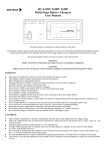
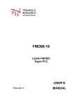
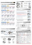
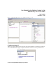
1
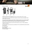
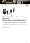
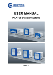
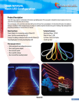
Technical Specification
and
Operating Procedure
PILATUS 300K
Version 1.1
Table of Contents
1
Document History .....................................................................................3
1.1
Changes ............................................................................................3
2 How to use this technical specification .....................................................4
2.1
Address and support..........................................................................4
2.2
Explanation of symbols......................................................................4
2.3
Explanation of terms ..........................................................................5
2.4
Use of the PILATUS 300K .................................................................5
3 Technical specification..............................................................................6
3.1
Ratings ..............................................................................................7
3.2
Ambient conditions ............................................................................8
3.3
Temperature shut down.....................................................................8
4 Dimensions and connectors......................................................................9
4.1
Backside of the detector ..................................................................11
4.2
Computer.........................................................................................12
5 Installing the detector system .................................................................14
5.1
Carrying ...........................................................................................14
5.2
Mounting..........................................................................................16
5.2.1
Mounting from the top...............................................................16
5.2.2
Mounting from the bottom.........................................................17
5.3
Earthing of the detector system .......................................................18
5.4
Connection to nitrogen.....................................................................19
5.5
Connecting the cables .....................................................................20
6 Getting started ........................................................................................21
6.1
Start .................................................................................................21
7 Cleaning and maintenance .....................................................................22
8 Faults ......................................................................................................23
9 Certification tests ....................................................................................24
10
Appendix .............................................................................................25
10.1 Table of figures................................................................................25
I
1 Document History
Actual document
Version
Date
status
prepared
checked
released
1.1
9.2.2009
Released
PS
EFE, MS
PS
1.1 Changes
Version
1.1
Date
9.2.2009
Changes
Changes in startup routine
Change of IP address
Fault finding added
Technical Specification-PILATUS 300K-V1_1.doc
3/25
2 How to use this technical
specification
Before you start to operate the PILATUS detector system please read this
technical specification and the user manual thoroughly.
The technical specification and the user manual form together the user
documentation.
This user documentation has been especially designed for DECTRIS
PILATUS detector systems.
2.1 Address and support
DECTRIS Ltd.
Neuenhoferstrasse 107
5400 Baden
Switzerland
Phone: +41 56 500 21 00
Fax: + 41 56 500 21 01
Email: [email protected]
Should you have questions concerning the system or its use, please contact
us via phone, mail or fax.
2.2 Explanation of symbols
Symbol
Description
Important or helpful notice
Caution. Please follow the instruction carefully to prevent
equipment damage or personal injury.
DC-current
AC-current
Ground
Technical Specification-PILATUS 300K-V1_1.doc
4/25
2.3 Explanation of terms
Term
MCB
DCB
DAC
Description
Module control board
Detector control board
Digital to Analog Converter
2.4 Use of the PILATUS 300K
The PILATUS 300K detector system has been designed for the detection of
X-rays from synchrotrons or laboratory sources.
It is intended for indoor use only.
For other applications, please contact DECTRIS for additional information.
Technical Specification-PILATUS 300K-V1_1.doc
5/25
3 Technical specification
Number of modules
Sensor
Sensor thickness
Pixel size
Module size
Format
Area
Intermodule gap
Dynamic range
Counting rate per pixel
Energy range
Energy resolution
Adjustable threshold range
Threshold dispersion
Readout time
Framing rate
Point-spread function
Cooling
Power consumption
Operating temperature
Dimensions (W x H x D)
Weight
1x3=3
Reverse-biased silicon diode array
320 µm
172 x 172 µm2
83.8 x 33.5 mm2
487 x 619 = 301’453 pixels
83.8 x 106.5 mm2
17 pixels = 2.924 mm
20 Bits = 1’048’576
> 2x10⁶ X-ray/sec
3–30 keV
500 eV
2 – 20 keV
50 eV
2.6 ms
200 Hz
1 pixel
Air-cooled
50 W
20 - 30°C
160 x 194 x 289 mm3
11 kg
Technical Specification-PILATUS 300K-V1_1.doc
6/25
3.1 Ratings
Device
Definition
Detector
Power Input
100 - 240 VAC, 50-60 Hz
400 Watt
It can be connected to all common supply
voltages.
Detector
External Trigger Input
5 V TTL; 5.0 V absolute maximum
Applying a higher voltage will destroy
the input
Detector
Enable output
3.3 V TTL
PC
100V-240 VAC; 8A - 4A
50/60Hz
960 Watt
It can be connected to all common supply
voltages.
Technical Specification-PILATUS 300K-V1_1.doc
7/25
3.2 Ambient conditions
The PILATUS 300K detector is designed only for indoor use according the
following ambient conditions.
Condition
Range
Operating temperature:
20°+ to 35° C
Operating humidity:
<70% at 20° C, non condensing
Storage temperature
15° to 40° C
Storage humidity
< 75% at 20° C, non condensing
If the detector system is stored in low temperature, make sure that
no condensation moisture develops.
3.3 Temperature shut down
The PILATUS 300K detector head has a temperature control mechanism,
which shuts the power of the detector modules down when the temperature
exceeds 45°C. The fan and communication with the PC will remain active.
An overtemperature error is displayed as follows: the TEMP and the POWER
LED on the back of the detector turns red.
Procedure:
1. Wait until detector cools down
2. Turn the detector off
3. Turn the detector on to reinitialize
Technical Specification-PILATUS 300K-V1_1.doc
8/25
4 Dimensions and connectors
Figure 1 Drawing of the PILATUS 300K detector (is printed separately in the user
manual folder)
The detector comes with a protective aluminum cover for the front window and
the sensor that should be removed for operation. The sensor is behind a 25
µm thick aluminized mylar foil to protect it from dust and touch.
The cover is mounted on four bolts and can be removed by lifting it sligthly up
and removing it.
When mounting the cover, make sure it fits into all four bolts.
Do not touch the mylar foil
The aluminium cover will not protect the detector from direct
synchrotron beam.
Technical Specification-PILATUS 300K-V1_1.doc
9/25
Figure 2 PILATUS 300K detector with aluminum cover in place (front view)
Figure 3 PILATUS 300K detector with aluminum cover removed (front view)
Technical Specification-PILATUS 300K-V1_1.doc
10/25
4.1 Backside of the detector
Figure 4 PILATUS 300K detector viewed from the back
Connector
DATA 1 (D1)
DATA 2 (D2)
DATA 3 (D3)
+12 V
EXT IN
Description
Data connection 1
Data connection 2
Data connection 3
Main voltage 12 VDC from external power supply
External Trigger Input (TTL, lemo connector)
EN OUT
Ground
The input voltage should not exceed 5V
TTL output signal; high when counting is enabled.
Grounding of the detector.
N2
Although the detector may be grounded via the
mounting bolts, the detector must be grounded via this
connector to establish a defined grounding.
Nitrogen for humidity control.
Recommended continuous flow: 1L / hour
Technical Specification-PILATUS 300K-V1_1.doc
11/25
LED
Power
Temp
EN
Description
If green, all supply voltages are ok
Red, if module power is off or with overtemperature
Normally green. Turns red when detector temperature
exceeds 45°C.
Yellow, detector is making an exposure
The fixation pieces are stored on the back of the detector.
4.2 Computer
The system is comes with two computers configuered as master and slave.
The slave is equipped with two proprietary data acquisition cards to
communicate with the detector, whereas the master is equipped with only one
card.
The PCs should be kept behind a firewall and shouldn’t have
outside internet access.
The operating system is optimized for high speed data acquisition
and has a custom kernel: Therefore do not permit any software upgrades on
the kernel
Technical specifications of the computers are in the system information sheet.
Figure 5 PCs from the back with 2 data acquisition cards inside and 3 data cables
connected
Technical Specification-PILATUS 300K-V1_1.doc
12/25
Figure 6 Detail of inteconnection between PC A and PC B. (Data cables not connected
for better demonstration)
Connector
Data 1, RX
Data 1, TX
Data 2, RX
Data 2, TX
Data 3, RX
Data 3, TX
Description
Receive
Transmit
Receive
Transmit
Receive
Transmit
PC
A
A
B
B
B
B
GB2, PC A
Interconnector between
PC’s
Ethernet
Do not connect
GB2. PC B
GB1
GB1
PC A
PC B
Make sure the data cables are tightened properly
Technical Specification-PILATUS 300K-V1_1.doc
13/25
5 Installing the detector system
5.1 Carrying
The detector has been delivered in a robust transport box. Please keep this
transport box for transport or storage purpose.
When carrying the detector, make sure the protection cover is
mounted.
Do not carry the detector this way
Technical Specification-PILATUS 300K-V1_1.doc
14/25
Correct carrying of the detector:
Technical Specification-PILATUS 300K-V1_1.doc
15/25
5.2 Mounting
The detector can be mounted in two ways:
5.2.1 Mounting from the top
From the top with the detachable mounting pieces, which are stored on the
back of the detector. These mounting pieces have to be mounted on the
baseplate of the detector.
Make sure the mounting pieces are mounted and tightened properly
Mounting points when mounting from the top
Technical Specification-PILATUS 300K-V1_1.doc
16/25
5.2.2 Mounting from the bottom
From the bottom with four M6 bolts.
Mounting points when mounting from the bottom
The four M6 bolts should not intrude into the detector more than 2
cm.
Make sure the detector is properly mounted.
Make sure the detector has enough space for proper ventilation.
The ventilator on the back of the detector should not be covered.
Do not use in vacuum.
The PC can be mounted in a standard 19 inch rack, which has to be properly
grounded.
Technical Specification-PILATUS 300K-V1_1.doc
17/25
Make sure that the PC has adequate ventilation.
5.3 Earthing of the detector system
Figure 7 Earth connector on the back of the detector
Although the PC is grounded via the ground connector in the power
plug, the housing of the PC should also be properly connected to a grounded
rack.
The mains plug of the computer and the power supply have to be
connected to a earthed power outlet.
Although the detector might be grounded via the mounting bolts, the
detector must also be grounded via the ground connector on the back to
establish a defined grounding.
Technical Specification-PILATUS 300K-V1_1.doc
18/25
5.4 Connection to nitrogen
The PILATUS detector has to be connected to a dry nitrogen flow to avoid
condensation when operated in humid conditions.
Figure 8 Nitrogen connector on the back of the detector
Humidity can damage the detector. Make sure to operate the
detector in the specified range.
Recommended
flow of nitrogen
As alternative
1 liter per hour.
Oil free, dry air of <2% R.H can be used.
Recommended flow: 1 liter per hour.
Technical Specification-PILATUS 300K-V1_1.doc
19/25
5.5 Connecting the cables
To operate the detector, the data cables and the ground should be connected:
Data cables:
The PILATUS 300K detector is equipped with 3 data cables, which are
numbered Data 1, Data 2 and Data 3. This marking is also on the data
acquisition computers.
Connect RX to RX and TX to TX on the GigaSTaR Card in the PC; the single
connectors go to the back of the detector.
The data cable should be pulled onto the computer connectors with
the screws, rather than forcefully pushed on.
A forceful connection can damage the PCI card.
It is important for data integrity that the screws be tightened.
To plug or unplug any cables, turn the detector off.
Technical Specification-PILATUS 300K-V1_1.doc
20/25
6 Getting started
Before operating the detector, make sure you have read the previous chapter
in the technical specification and the user manual.
Check these items before turning the detector system on:
•
•
•
•
Mount the detector properly
Connect the detector to power
Connect the detector to nitrogen
Connect the PCs and the detector with data cables
6.1 Start
•
•
•
•
•
•
•
Attach a monitor and keyboard to computer A. It is not necessary to
have these on computer B.
Turn the detector on
Turn on PC B (slave)
Wait approximately a minute, until it is fully booted
Turn on PC A (master)
In a shell on PC A
o ping 10.0.0.2 (until a connection is established)
o ssh [email protected]
o (you are now on PC B)
o cd p2_det
o runtvx
o wait until “disconnect” is executed
o don’t close this window
In an other shell on PC A
o cd p2_det
o runtvx
Runtvx starts a script file which initializes the detector system and opens
the Camserver and TVX windows.
Technical Specification-PILATUS 300K-V1_1.doc
21/25
7 Cleaning and maintenance
The housing should be cleaned with a soft tissue.
The mylar foil should not be touched or cleaned
The PILATUS 300K detector system is maintenance free.
Technical Specification-PILATUS 300K-V1_1.doc
22/25
8 Faults
Problems
PC doesn’t start
properly
Causes
PC cards not properly
mounted
Detector shuts
down
Overtemperature error
Detector shuts down if
the temperature
exceeds 45°C.
Check the LED on the
back of the detector:
Power LED: red
Temp LED: red
Images look
strange after
initialization
After a trigger
command has
been issued
camserver reports
an error
Error while taking
images
Overcurrent
Threshold level set too
low and the detector
starts oscillating
Detector not properly
initalized
After issuing the trigger
command in camserver
a trigger has to occur
within 15 seconds
Solution
Open the PC and check that
the PC cards are properly
mounted and tightened
• Wait until the detector
cools down
• Restart the detector again.
• Check the temperature of
the detector with the
command in camserver:
“TH 0”. This shows the
inside temperature of the
detector.
• Check that the ventilator of
the detector is running
properly and the ventilation
holes are not covered
• Increase the threshold
level
Run the following commands
in TVX:
• calibdet
• setdac
• expose
Make sure the trigger
command occurs within 15
seconds
Camserver on slave pc
not running
Technical Specification-PILATUS 300K-V1_1.doc
Make sure that
cam_server.sh is running
on the slave pc. See
chapter 6.1.
23/25
9 Certification tests
The following tests have been accomplished and passed:
Technical Specification-PILATUS 300K-V1_1.doc
24/25
10 Appendix
10.1 Table of figures
Figure 1 Drawing of the PILATUS 300K detector (is printed separately in the
user manual folder) ..........................................................................................9
Figure 2 PILATUS 300K detector with aluminum cover in place (front view) .10
Figure 3 PILATUS 300K detector with aluminum cover removed (front view)10
Figure 4 PILATUS 300K detector viewed from the back................................11
Figure 5 PCs from the back with 2 data acquisition cards inside and 3 data
cables connected ...........................................................................................12
Figure 6 Detail of inteconnection between PC A and PC B. (Data cables not
connected for better demonstration) ..............................................................13
Figure 7 Earth connector on the back of the detector ....................................18
Figure 8 Nitrogen connector on the back of the detector ...............................19
Technical Specification-PILATUS 300K-V1_1.doc
25/25