1
User's Manual
DATA DISPLAY GROUP
6.3 Device Setup
6.3.1 Device Info
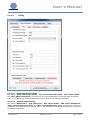
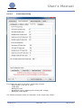
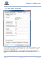
First choose the appropriate serial port from the drop-down box at the bottom of the window. To
test if the communication with the board is working, click on the “Detect” button. If the
connection is OK the Board Type and the Firmware Version is shown in the “Device Info” section.
Note that board detection is only possible if a valid FW is running on the board. On a new and
empty board this operation will time out - in this case flash a FW first.
6.3.2 Device Storage
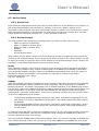
The radio buttons allow selecting the storage device you want to read, write or erase:
- EDID #0 (DVI on Prisma-IIIa)
- EDID #1 (HDMI on Prisma-IIIa)
- EDID #2 (VGA on Prisma-IIIa)
- NVRAM
- SPI Flash
- All the devices above
After clicking on the “Read”- button you will be asked to choose an output file name where the
content of the selected storage device will be saved. After clicking on the “Write”-button you will
be asked to choose an input file which will be written to the selected storage device. Section 2.2
explains in more detail which data are stored in which device.
EDIDs
Note that after clicking on the “Detect” button the port is shown to which the particular EDID is
connected (DVI, HDMI or VGA). Please be aware that not all EDIDs are available on all boards there might be assembly variants where not all EDIDs are populated even if they are shown in
MarsRover. Access to the EDIDs is only possible if a valid FW is running on the board.
Input and output file type: Binary
File size: 256 Bytes
NVRAM
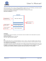
OSD user settings, the panel configuration and the board configuration are stored in the NVRAM.
Note that the NVRAM is always written and read completely. This is important to understand
because the panel- and board configuration can be loaded separately to the NVRAM (see section
6.4 and 6.5). Writing the NVRAM will therefore always overwrite the previously loaded panel- and
board configuration, on the other hand the read NVRAM-file will always include the currently
loaded panel- and board configuration. There are two possible scenarios the user must be aware
of when the NVRAM has to be written:
-
-
The provided NVRAM file already includes a valid panel- and board configuration: In this
case there is no need to separately load the panel- and board configuration after writing
the NVRAM.
The provided NVRAM file does not include a valid panel- and board configuration: In this
case the NVRAM file must be written first, after this the panel- and board configuration
can be written.
In case the Power-On-Time counters are enabled (see sec. 6.5.2), then these counter values are
also stored in the NVRAM. This has the consequence that erasing the NVRAM also erases the
counter values and resets them to zero.
Also note that the NVRAM data is FW version specific. When you read for example an NVRAM file
from a board with FW version 2.4, you can (in most cases) not use this NVRAM file for a board
MarsRover 1.8
Manual Rev. 1.8.0
Page 8 of 27