1
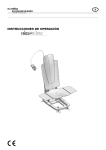
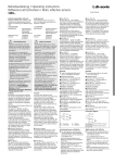
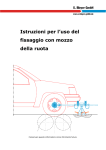
LC 100 Operating Instructions Cross-cutting machine LC 100 Date of issue: 04/2013 LC 100 Table of contents 1 2 3 A i Basic information ....................................................................................................................1-1 1.1 Intended use....................................................................................................... 1-1 1.2 For your safety.................................................................................................... 1-1 Operating the LC 100 ..............................................................................................................2-1 2.1 Scope of supply and overview ............................................................................ 2-1 2.2 Setting up the LC 100 ...................................................................................... 2-2 2.3 Connecting and inserting the cable .................................................................... 2-3 2.4 Automatic cable cutting ...................................................................................... 2-4 2.5 Planning cutting jobs with a PC........................................................................... 2-5 2.6 Manual cable cutting........................................................................................... 2-7 2.7 Exiting from cutting ............................................................................................. 2-7 Troubleshooting ......................................................................................................................3-1 3.1 Error messages on the Display........................................................................... 3-1 3.2 The length cut is wrong....................................................................................... 3-2 3.3 Adjusting the cable conveyor speed ................................................................... 3-2 3.4 LC 100 will not switch on .................................................................................... 3-3 3.5 Adjusting or replacing the rollers ........................................................................ 3-4 3.6 Replacing the cutters ......................................................................................... 3-5 Appendix ................................................................................................................................ A-1 GLW A1 Ordering data .................................................................................................... A-1 A2 Technical data ................................................................................................... A-1 102786_en_01 1 Basic information 1.1 Intended use The LC 100 cutting machine cuts cables, litz wires, shrink sleeves and similar profiles and is particularly suitable for series production. The LC 100 is exclusively intended for cutting cables, litz wires, shrink sleeves and similar profiles up to 8 mm. Please note that only finely stranded copper litz wires up to 10 mm2 and solid copper cables up to a maximum of 2.5 mm2 may be used. Steel wires or similar may never be used, as these would destroy the cutter. Willful modifications to the LC 100 are prohibited for safety reasons. The required length and number of wires is entered either directly in the LC 100 with the keypad or can be documented on the PC with the supplied software and loaded to the LC 100. WARNING: The LC 100 may only be used – as intended and – when in perfect working order regarding safe functioning. WARNING: All persons responsible for commissioning, operating and maintenance of the LC 100 must be appropriately qualified and have read this user manual. In particular, they must be able to recognize dangers. NOTE: Only use original replacement parts from Phoenix Contact. 1.2 For your safety WARNING: The front door is installed for the safety of the operator. It is prohibited in all circumstances to modify, remove or by means of alterations bypass it. The LC 100 may be operated only when the front door is closed. Disconnect the mains plug before beginning maintenance work. Make sure that there are no foreign objects inside the housing. 102786_en_01 GLW 1-1 English Basic information LC 100 2 Operating the LC 100 2.1 Scope of supply and overview Figure 2-1 1 RS-232 interface 11 Metering roller 2 Mains connection 12 Insertion slot 3 Mains fuses 13 Door opener 4 Mains switch 14 Display 5 Adjusting screw 15 Key pad 6 Drive rolls 16 Allen key, size 3 7 Cutter 17 Removal hook 8 Outlet slot 18 Power cable 9 Cable routing 19 RS-232 cable 10 Front door 2-1 GLW Scope of delivery and overview of the operating components Not pictured: CD-ROM, user manual 102786_en_01 2.2 Setting up the LC 100 NOTE: The device must be set up on a level and horizontal surface. NOTE: During operation and storage, avoid the following: – humid or dusty places and – locations exposed to high levels of heat, direct sunlight or low temperatures (operating range: 15°C ... 35°C). NOTE: Set up the LC 100 so that it cannot slip from its work surface. Use a non-slip mat or fix the LC 100 in place, as depicted in Fig. 2-2 (right). Figure 2-2 Example for fixing the LC 100 NOTE: Do not spill liquids on the LC 100. Do not expose the LC 100 to strong vibrations or shocks. NOTE: If the machine is moved from a cold location to a warm location, condensation can form. Before using the LC 100, open the front door and allow condensation to evaporate. 102786_en_01 GLW 2-2 English Operating the LC 100 LC 100 2.3 Connecting and inserting the cable Connecting to mains • • Connect the power cable (2). Switch on the LC 100 with the mains switch (3) (press I). The display (4) and the red "stop" LED (5) light up. Inserting the cable • • • Press the door opener (1) and fold down the front door (2). The rollers are raised (3). Insert the cable between the rollers and pull it through the cable routing and out through the outlet slot (4). Fold up the front door (6). The rollers clamp the cable firmly (5). If you cut very soft or hard material, it is advisable to change the clamping pressure (see page 3-4). Adjusting the measuring unit between millimeter and inch The default is millimeter. • Press and hold the "mode" button for approx. six seconds, until this display appears. • Press the "4" key for mm/inch adjustment. The measuring unit currently in use is framed (here, it is mm). • The "2" key sets the measuring unit to mm. The "8" key sets the measuring unit to inch. • Press the "enter" key to save the value and return to mode selection. With the "mode" button, you can return to mode selection without saving. 2-3 GLW 102786_en_01 2.4 Automatic cable cutting The LC 100 cuts the amount entered automatically to a specified length. This is the default mode and is active when the machine is switched on. • Switch on the LC 100. • Insert the cable as described (see page 2-3). • To switch into this mode, press the "mode" button and then the "1" key. Length (mm or inch, see page 2-3) Number of cuts To go (Number of cuts remaining) Entering the parameters • • • • Enter the length and number of cuts with the keys "0" to "9". You can overwrite the values or delete them with the "C" button. For entries in inches, decimal places can be used. Switch to the next line with the "enter" key. Cutting the cable • Press the "start" button. The green LED lights up. The cable is then cut automatically. Pausing or stopping the cable • Cutting can be interrupted. To do this, press the "stop" button. The red "stop" LED flashes. Press the "start" button to continue cutting. If you would like to stop cutting, press and hold the "stop" button for at least two seconds. The To go display is set to "0000". • • Cutting finished When the cutting is completed, the To go display reads "0000" and a checkmark is shown. The length and number can be re-entered. Changing modes 102786_en_01 • Press the "mode" button to switch back to mode selection. GLW 2-4 English Operating the LC 100 LC 100 2.5 Planning cutting jobs with a PC Data records with cutting jobs can be created at a PC. The data records contain information about the desired number and length as well as a description of the cable. These data records are then processed sequentially from the LC 100. You can store and process up to 20 projects (lists) with a maximum of 100 data records (cutting jobs). Connecting the LC 100 to a PC • • • • • Switch off the LC 100 and the PC before connecting. Connect the LC 100 to a PC with the RS-232 cable supplied. The RS-232 interface is on the back side of the LC 100. Switch the LC 100 and the PC back on. Create the cutting jobs at the PC with the help of the LCExcel 2 software supplied. Switch into the appropriate mode. Press the "mode" button and then the "2" key. Number of data records Project number Text description Loading a project to the LC 100 • Load the desired project to the LC 100 with help of the software. While the project is being loaded to the LC 100, a display appears on the screen. When it is finished loading, a display for project selection appears. Project selection • Select the project number. The "2" key lowers this number. The "8" key raises this number. Press the "enter" key to confirm the selection. • Then the settings for the selected project are displayed. Project number Data record number Number of data records 2-5 GLW Length Number To go Text description 102786_en_01 Deleting a project • If you would like to delete the current project, press and hold the "stop" button for at least two seconds. This display appears. • • To delete the project and return to project selection, press the "2" key. To return to project selection without deleting, press the "enter" key. Changing settings The values for length and number shown in project selection can be edited. The changes remain until the project is switched or closed. Permanent changes have to be made at the PC and then loaded to the LC 100. If, for example, a data record has been created where more cable is cut than actually required, then the number can be decreased here. But the next time this data record is accessed, the higher number, which is saved, will be used. • Select a data record with the keys "0" to "9". • You can overwrite the values or delete them with the "C" button. • Switch to the next line with the "enter" key. • Enter the length and number of cuts with the keys "0" to "9". • For entries in inches, decimal places can be used. Cutting the cable • • Insert the cable as described (see page 2-3). Press the "start" button. The green LED lights up. The LC 100 then processes all of the project's data records automatically. Pausing or stopping the cable • Cutting can be interrupted. To do this, press the "stop" button. The red "stop" LED flashes and this display appears. • • Press the "start" button to continue cutting. To stop cutting, press the "mode" button to switch to another data record or close the project. End of the project The cutting is finished when this display appears. • • 102786_en_01 To return to project selection, press the "enter" key. To delete the completed project and return to project selection, press the "C" key. GLW 2-6 English Operating the LC 100 LC 100 2.6 Manual cable cutting The cable can be moved and cut using button commands. • Insert the cable as described (see page 2-3). • Switch on the LC 100. • To switch into this mode, press the "mode" button and then the "3" key. Length moved (mm or inch, see page 2-3) Cutting Cutting cable • • Press and hold the "6" key until the cable has been moved the desired length. Press the "2" key to cut the cable. Deleting the length • Press the "C" key to delete the set length. Changing modes • Press the "mode" button to switch back to mode selection. 2.7 • • 2-7 GLW Exiting from cutting When no more cable is to be cut, switch off the mains switch (press 0). Open the front door and remove the cable. 102786_en_01 3 Troubleshooting 3.1 Table 3-1 Error messages on the Display Error messages and remedies Display The error is triggered when the motor receives current but the metering rollers are not turning. Cause Remedy Front door is open. • Close front door. The metering roller does not detect a cable. • Insert a new cable. While conveying the cable, it jammed or made a knot. The drive rollers slip. • Check if there is a jam or knot. The force required to unwind the cable is too large. The drive rollers slip. • Check if the force required to unwind the cable is too large. The rollers do not convey the cable properly. The drive rollers slip. • Adjust the clamping pressure of the drive rollers (see page 3-4). Replace the drive rollers (see page 3-4). Use drive rollers that suited to the cable (see page A-1). • • The metering roller slips past the cable. • • The error is triggered when the motor current increases too fast. Check if the metering roller is worn. Use a metering roller that suits the cable (see page A-1). While conveying the cable, it jammed or made a knot. The drive rollers are locked or are about to lock. • Check if there is a jam or knot. The force required to unwind the cable is too large. The drive rollers are locked or are about to lock. • Check if the force required to unwind the cable is too large. Maximum cutting force exceeded • Check if the cable cross section is too large or if the cable is for some other reason not suitable. Switch the cutter (see page 3-5). • Press the "enter" key to delete the error message. Metering and drive rollers Drive rollers Metering roller 102786_en_01 GLW 3-1 English Troubleshooting LC 100 3.2 • • • The length cut is wrong Check if the drive or metering rollers are worn and replace them. Adjust the clamping pressure of the drive rollers (see page 3-4). If the insulation of the cable is very hard, the metering roller can be exchanged with a PU roller or a steel roller (see page 3-4). If the actual length cut is not consistent with the length set, the LC 100 has to be readjusted. • Press and hold the "mode" button for approx. six seconds until this display appears. • Press the "1" key to adjust the length. A value for length adjustment is displayed (here: 5659). This value indicates the number of pulses per meter. • The "2" key lowers this value and with it the length conveyed. The "8" key raises this value and with it the length conveyed. • Press the "enter" key to save the value and return to mode selection. With the "mode" button, you can return to mode selection without saving. 3.3 Adjusting the cable conveyor speed The speed with which the cable is moved can be adjusted. This speed can be adjusted separately for automatic and manual modes. • Press and hold the "mode" button for approx. six seconds until this display appears. • Press the "2" key to change the speed in automatic mode and the "3" key for manual mode. • The speed is preset to 100% and can be lowered. The "2" key lowers this value and thus the speed. The "8" key raises this value and thus the speed. • Press the "enter" key to save the value and return to mode selection. With the "mode" button, you can return to mode selection without saving. 3-2 GLW 102786_en_01 3.4 LC 100 will not switch on No mains connection • • Check whether the mains plug is connected to the LC 100 mains connection and the shock-proof plug is connected to the mains socket. Make sure that the power supply at the mains socket is OK. Mains fuse blown WARNING: Risk of injury Switch off the LC 100 (1) and disconnect the mains plug (2). • • • • Remove the fuse holder (3). Check the mains fuses (4). Replace the blown mains fuse (for ordering data see page A-1). Push the fuse holder back in NOTE: The fuse holder should snap into place. 102786_en_01 GLW 3-3 English Troubleshooting LC 100 3.5 Adjusting or replacing the rollers Adjusting the clamping pressure of the drive rollers (B) The clamping pressure must suit the cable. For standard cable, it does not need to be changed. The following generally applies: – Hard and thick material: more pressure – Soft and thin material: less pressure B • • B Press the door opener and fold down the front door. Set the clamping pressure with the adjusting screw. Rotate left more pressure Rotate right less pressure Replacing drive or metering rollers WARNING: Risk of injury Switch off the LC 100 and disconnect the mains plug. B • • Press the door opener and fold down the front door. Insert the removal hook (1) supplied behind the rollers (2) and push off the rollers. A NOTE: Replace the drive rollers (B) in pairs only. Pay attention to the flat guiding surface (3) when mounting. B • • • 3-4 GLW Replace the rollers (for ordering data see page A-1). Fold up the front door. Plug in the mains plug again. 102786_en_01 3.6 Replacing the cutters Removing the drive rollers WARNING: Risk of injury Switch off the LC 100 and disconnect the mains plug. • • Press the door opener and fold down the front door. Insert the removal hook (1) supplied behind the rollers (2) and push off the rollers. Removing the cutters • • Loosen the screws (1) with the Allen key supplied. Remove both cutters (2 and 4). Mounting the cutters NOTE: Always replace both cutters. Pay attention when mounting that the slanted cutting surfaces (3) face outwards. • • • Place the lower blade (4) with the threaded insert onto the holder from the right. Place the upper blade (2) onto the holder from the left. Tighten the screws with the Allen key. NOTE: Pay attention to the position of the flat guide surfaces on the shafts (5) when mounting the rollers. • • • 102786_en_01 Remount the drive rollers. Fold up the front door. Plug in the mains plug again. GLW 3-5 English Troubleshooting LC 100 A Appendix A1 Ordering data Cutting machine Description Order No. Pcs./Pkt. Cutting machine LC 100 1 Order No. Pcs./Pkt. Standard rollers LC1 ROL 1 pair Rollers with PU contact surface LC1 ROL PU 1 Rollers with a hardened, finely knurled steel contact surface LC1 ROL SS 1 Cutter LC1 EM 1 set Mains fuse T 2A/250V (20 x 5 mm) On request 1 pair Tool set (removal hook and Allen key) LC1 AH 1 Replacement parts Description Drive / metering rollers A2 Technical data Technical data Mains connection 90 V ... 264 V / 47 Hz ... 63 Hz Power consumption 150 VA Cutting efficiency (flexible/solid) 0.08 mm2 ... 10 mm2/0.08 mm2 ... 2.5 mm2 Maximum throughput 8 mm Cross section setting Automatically Number of cuts 1 ... 9999 Pcs. Length of cuts 2 mm ... 999999 mm/0.1 in. ... 99999.9 in. Feed rate max. 0.5 m/s Interface RS-232 Dimensions (W x H x D) 194 mm x 228 mm x 301 mm Weight 10 kg A-1 GLW 102786_en_01 EC Declaration of Conformity Manufacturer: GLW GmbH Address: Steinbeisstraße 2 88353 Kisslegg Germany LC 100 We hereby declare that the concept and design machine described below, as well as the fittings marketed by us, conform to the relevant basic safety and health requirements of the EU Machines Directive. This declaration shall become invalid in the event of unauthorised modifications to the machine. Name of the machine: Cross cutting machine Machine type: LC 100 Relevant EC directives: EG-Machine Directive 2006/42/EG EC-Electromagnetic Compatibility Directive 2004/108/EG Applied harmonized standards: DIN EN ISO 12100:2011-03 DIN EN ISO 13857:2008-06 DIN EN 349:2008-09 DIN EN 60204-1:2007-06 DIN EN 61000-6-2; VDE 0839-6-2:2006-03 DIN EN 61000-6-3; VDE 0839-6-3:2011-09 Place, date Kisslegg, 07. March 2013 Legally binding signature: Information about the signing person: Bruno Weiland LC 100 GLW GmbH Steinbeisstraße 2 88353 Kisslegg Germany Tel. (+49) 7563 9123-0 Fax (+49) 7563 9123-99 The company GLW holds the copyright on these operating instructions. Reprinting, copying or translation are not permitted, either in whole or in part, without permission. 2013 GLW GmbH