1
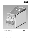
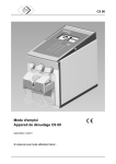
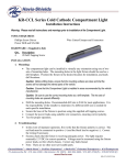
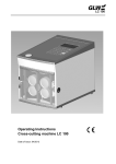
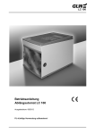
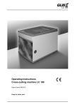
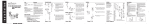
AC 100 Operating instructions Pneumatic Crimper AC 100 Date of issue: 05/2010 Keep for future use! AC 100 SAFETY AC 100 SAFETY Basic information The basic prerequisite for ensuring safe use and continuous operation of the AC 100 is knowledge of and compliance with the safety instructions. It is a question of your own safety! All persons working with the AC 100 must observe the notes on safety. In addition, rules and regulations which apply to the place of use, particularly regarding accident prevention, must be observed. Symbols The following symbols will be used in these operating instructions: indicates a possible accident or injury hazard and/or possible damage to the AC 100. ! indicates notes on application. Dangerousness of the machine The AC 100 has been constructed according to recognised technical safety regulations and has undergone a safety examination and received official acceptance. It is equipped with safety devices. However, operating error and misuse could present a danger to life and limb of the operator, the machine. The AC 100 should only be used for the designated application and in perfect condition with regard to technical safety. All persons involved with commissioning, operating and maintaining the AC 100, must be appropriately qualified and follow these operating instructions precisely. 05/10 1 AC 100 SAFETY Designated use The AC 100 is to be used exclusively for crimping wire-end ferrules with cross sections between 4 and 10 mm². Under no circumstances should large metal parts or similar objects be introduced; the die set will be ruined. Unauthorised amendments to the AC 100 are prohibited for safety reasons! ! Observation of all instructions and compliance with the prescribed operating conditions are part of the designated use. Sources of danger The AC 100 must only be operated when the finger guard plate is screwed on. Only filtered compressed air with a maximum pressure of 6 bar can be used. Disconnect the machine from the compressed air before working on the AC 100, during breaks and when the device is not in use. Do not pull on the compressed air tubing to disconnect. Work places The following should be avoided for operation and storage: damp or dusty places, places which are subject to high levels of heat, direct sunlight or low temperatures (operating range: 15 °C to 35 °C). Protect the compressed air tubing from heat, oil and sharp edges. Safety devices The AC 100 has a finger guard plate at the front as a contact safety device. Under no circumstances should this be removed. The AC 100 is stopped when disconnected from the compressed air supply. Permitted operators Only authorised and instructed operators can work on the AC 100. The operator is responsible to third parties in the working area. The owner must make the operating instructions available to the operator and make sure that the operator has read and understood them. 05/10 2 AC 100 SAFETY Guarantee In principle, our "General terms of purchase and delivery" apply. These are available to the owner when the contract is concluded at the latest. Guarantee and liability claims resulting from damage to personnel or property are inadmissible if the following points have been violated: Non-designated use of the AC 100. Inappropriate working places. Inappropriate use and use which goes beyond that described in the operating instructions. Unauthorised structural amendments to the AC 100. Continued use of the AC 100 when a malfunction has been established. Repairs carried out inappropriately. ! 05/10 Only use original spare parts. 3 AC 100 DESCRIPTION Application The AC 100 is a pneumatic crimping tool for wire-end ferrules with a cross-section of between 4 and 10 mm². On account of its handy design it is ideally suited to wiring electrical cabinets. Components 1 Compressed air tubing 2 Lever 3 Body 4 Head 5 Die set 6 Finger guard plate Accessories 7 Magnetic holder Fig. 1 05/10 Spare parts 4 AC 100 MAINTENANCE Commissioning Check whether finger guard plate (1) is present and is sitting firm. Check whether the die set (2) is free from foreign matter. Check whether the pneumatic tubing nuts (3) have been tightened firmly. Check the compressed-air supply: min. 4 bar, max. 6 bar filtered air. Connect the tubing plug-in connector (4) to the compressed-air supply. Fig. 2 Putting into operation Fig. 3 Operation Operation Introduce stripped wire, with wire-end ferrules already fitted, at the side (1) in the hole assigned to the cross-section. Press the lever (2), the crimping process will be triggered. Release the lever (3), the crimped wire can be removed again (4). 05/10 5 AC 100 MAINTENANCE The AC 100 must be opened. Disconnect compressed air! Cleaning Unscrew hexagon socket screw (1). Pull out die set (2). Clean die set (3) and lightly oil pivot (4). Push in die set (5). Tighten hexagon socket screw (6). Fig. 4 Cleaning Fig. 5 Lubrication Lubrication Unscrew the head (1). Remove the spring (2) and piston (3). Lubricate the two arms of the die set (4) (e. g. Gleitmo 746). Insert piston and spring. Insert head (5) and fasten fingertight. Pay attention that the arms of the die set (4) are correctly engaged in the piston (3). 05/10 6 AC 100 TECHNICAL DATA The following spare parts can be ordered with the Address appropriate Article No. GLW GmbH Steinbeisstraße 2 D-88353 Kisslegg Tel. 00 49 (0) 7563 9123-0 Fax 00 49 (0) 7563 9123-99 Fig. 6 Spare parts No. Part Article No. No. Part Article No. 1 Compressed air tubing 2516 8 Hexagon socket screw 2504 2 Body 2508 9 Pivot pin 2503 3 Sealing ring 2520 10 Die set 10001 4 Piston 2507 11 Finger spring 2502 5 Spring 2506 12 Finger guard plate 10000 6 Head, complete 10040 13 Magnetic holder DX 7 Head section 10005 05/10 7 AC 100 TECHNICAL DATA Instrument........................................................................................................... Pneumatic Crimper Crimping range ................................................................................................................. 4 -10 mm² Compressed-air connection .............................................................................................. min. 4 bar ........................................................................................................................................ max. 6 bar Air consumption ............................................................................................. 0.2 l/Crimping at 5 bar Dimensions (diameter x length).....................................................................................44 x 190 mm Weight .........................................................................................................................approx. 450 g Name plate Type Crimping range Compressed air connection Model year Series number 05/10 Manufacture EU Symbol 8 AC 100 EC Declaration of conformity Manufacturer: GLW GmbH Address: Steinbeisstraße 2 88353 Kisslegg Germany We hereby declare that the machine described in the following complies with the appropriate fundamental health and safety requirements of the EC Directives regarding machinery with regard to its design and construction as well as the equipment that we have introduced onto the market. This declaration is rendered invalid in the case of amendments to the machine that have not been authorised by our company. Designation of the equipment: Pneumatic Crimper Machine type: AC 100 Appropriate EC Directive: 2006/42/EG Harmonisation standard used: DIN EN ISO 12100-1 und -2:2004 DIN EN ISO 13857:2008 DIN EN 349:2008 Place, Date Kisslegg, 10. December 2009 Legally binding signature: Particulars regarding signatory: 05/10 Bruno Weiland 9 GLW GmbH Steinbeisstraße 2 88353 Kisslegg Germany Tel. 00 49 (0) 7563 9123-0 Fax 00 49 (0) 7563 9123-99 The company GLW retains the copyright to these operating instructions. It is not permitted to reprint, reproduce or translate, even excerpts, without our consent. 2010 GLW GmbH