1
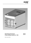
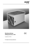
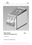
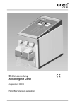
LC 100 Operating Instructions Cross-cutting machine LC 100 Date of issue: 08/2012 Keep for future use! CONTENTS LC 100 Safety......................................................................................... 1-3 Basic information ................................................................................................... 1 Symbols................................................................................................................. 1 Hazards posed by the machine.............................................................................. 1 Correct use ............................................................................................................ 2 Hazard sources...................................................................................................... 2 Workstations .......................................................................................................... 2 Safety fixtures ........................................................................................................ 3 Authorised users.................................................................................................... 3 Warranty ................................................................................................................ 3 Description................................................................................ 4-6 Use ........................................................................................................................ 4 Components .......................................................................................................... 4 Putting into operation .............................................................. 7 AUTO MODE.............................................................................. 8 MANUAL MODE ........................................................................ 9 PC MODE................................................................................... 10 - 11 ADJUSTMENT MODE ............................................................... 12 Self-help .................................................................................... 13 - 15 Spare parts................................................................................ 16 - 17 Technical data........................................................................... 18 Rating plate............................................................................................................ 18 EG Conformity Declaration ...................................................... 19 08/12 SAFETY LC 100 Basic Information Knowledge of and observing the safety instructions are basic requirements for the safe handling and fault-free operation of the LC 100. Your safety is a stake! The safety instructions must be followed by all persons who work with the LC 100. The regulations and specifications, particularly those relating to accident prevention, must also be observed. Symbols The following symbols are used in these operating instructions: indicates a possible accident and injury hazard or possible damage to the LC 100. ! indicates instructions for use. Hazards posed by the machine The LC 100 is constructed in accordance with the recognised safety regulations and has undergone a safety inspection and safety approval. It is fitted with safety fixtures. However, in the event that it is operated incorrectly or is misused, it poses hazards to the user’s life and safety, the machine itself. The LC 100 may only be used for its intended purpose and when it is in perfect condition from a safety point of view. All persons involved in the putting into operation, operation and maintenance of the LC 100 must be suitably qualified and observe these operating instructions precisely. 08/12 1 SAFETY LC 100 Correct use The LC 100 is intended exclusively for cross cutting cables, litz wires, shrink sleeves and similar profiles up to a diameter of 8 mm. Only finely stranded copper litz wires up to 10 mm2 and single-strand copper cables up to max. 2.5 mm2 may be used here. On no account may steel wires or similar be used, as these would destroy the cutting blade. Unauthorised modifications to the LC 100 are prohibited for safety reasons! ! Correct use also involves observing all instructions and adhering to the specified operating conditions. Hazard sources The LC 100 may only be used with the front door closed. Pull out the main plug before carrying out maintenance work. Ensure that there are no foreign objects inside the housing. Workstations The following places must be avoided for operation and storage: damp or dusty locations, locations subjected to high temperatures, direct sunlight or low temperatures (operating range: 15 °C to 35 °C). Condensation can form following a change of location from a cold to a warm place. Before using the LC 100, open the front door and allow condensation to evaporate. Do not spill any liquid onto the LC 100. Do not subject the LC 100 to strong vibrations and impacts. 08/12 2 SAFETY LC 100 Safety fixtures The LC 100 is switched off by the mains switch (0 pressed, display and red LED Stop dark). pulling out the mains plug. opening the front door (via safety switch). The front door is installed for the user’s safety. Under no circumstances may it be modified, removed or bypassed by conversions. The plate indicates the hazards involved. Authorised users Only authorised and trained users may work on the LC 100. The user is responsible for third parties in the working area. The operator must make the operating instructions available to the user and ensure that the user has read and understood these instructions. Warranty Our “General Sales and Delivery Conditions” always apply. These are made available to the operator no later than when the contract is concluded. Warranty claims and liability claims for injury and property damage shall not be possible if any of the following points are contravened: Incorrect use of the LC 100. Disorderly workplaces. Incorrect use and use which exceeds the purpose described in the operating instructions. Unauthorised structural modifications to the LC 100. Continuing to operate the LC 100 even if faults have been detected. Incorrect repairs. ! 08/12 Use only original spare parts. 3 DESCRIPTION LC 100 Use The LC 100 cross cutting machine cuts cables, litz wires, shrink sleeves and similar profiles up to 8 mm in diameter, making is particularly well suited for series production. The required length and number of wires is entered either directly on the LC 100 via the keypad or can be processed and documented on the PC with the supplied software. The LC 100 can then be directly controlled and process the cutting commands from the PC via the integrated RS232 interface. The LC 100 is available for a mains connection 230 V/50 Hz or 120 V/60 Hz. Components Fig. 1 08/12 Components 4 DESCRIPTION 1 2 3 4 Mains connection Mains fuses RS232 interface Mains switch 5 Adjustment screw 6 7 8 9 10 11 Drive rollers Cutting blade Outlet slot Guide Front door Roller spreading mechanism Measurement rollers Insertion slot Door opener Display Keypad 0–1 12 13 14 15 16 C LC 100 For mains cable (2 ea.) For PC connection Switches the power supply on (I pressed) or off (0 pressed). After switching on, the display and the red LED stop light up. For stepless adjustment of the drive roller application pressure Top position min. Bottom position max. For cable feed For cross cutting the cable For removing the cable For cable For inserting the cable For the cable length For cable For the front door To display the operating parameters To operate the LC 100 Number keys for entering operating parameters. The input point is indicated by the flashing cursor on the display. Inputs can be overtyped from left to right. Delete button for incorrect inputs. All inputs in the line marked by the cursor are set to 0 Fig. 2 enter mode start stop 08/12 Keypad Button for cursor control Button for operating mode selection Button for operation start (green LED lights up during operation, red LED goes out) Button for interrupting operation and deleting displays (red LED lights up during operation stop, green LED goes out) 5 DESCRIPTION LC 100 Accessories 17 Hexagon spanner 18 Removal hook 19 20 CD-ROM RS232 cable (Size 3) for cutting blade is located on the underside of the housing For roller changes is located on the underside of the housing. For PC operation LC 100 / PC, 2 m 22 Mains cable For the power supply 08/12 6 PUTTING INTO OPERATION LC 100 1. Selecting the installation location The installation location must be level and horizontal. ! The conditions outlined in the SAFETY chapter, Workstations section, must be observed. 2. Connecting / switching on the LC 100 Connect the mains plug on the mains connection (1) and to the socket. Ensure that the mains voltage is correct (see the rating plate (2)). Switch on the LC 100 with the mains switch (3) (press I , the display (4) and the red LED stop (5) light up). Figure 3 Connecting the LC 100 3. Selecting the operating mode After switching on, the display shows Auto mode. QUANTITY: XXX LENGTH: XXXXX mm TO GO: XXX Fig. 4 Auto mode The display shows Manual mode if the “mode“ button is pressed 1x. LENGTH: CUTTING: (6) (2) Fig. 5 Manual mode The display shows PC mode if the “mode“ button is pressed 2x. PROJECT: X D.REC: XX QUANTITY: XXX GO TO: XXX LENGTH: XXXXX mm XXXX mm2 “Colour “ Fig. 6 PC mode The display shows Adjustment mode if the “mode“ button is pressed for approx. 5s. ADJUSTMENT: XXXX mm SPEED HAND: X SPEED AUTOM.: X Fig. 7 Adjustment mode Repeatedly pressing the “mode“ button enables the mode to be selected. The present valid values “X“ and the selected “colour“ are shown on the display. The buttons (6) and (2) are displayed in Manual Mode. 08/12 7 AUTO MODE LC 100 1. Inserting a cable Press the door opener (1). Fold down the front door (2). The rollers (3) are raised. Insert a cable between the rollers and pull it through the guide and out through the outlet slot (4). Fold up the front door (5). The rollers (6) clamp the cable firmly. Fig. 8 Inserting a cable 2. Entering operating parameters Enter the “Quantity“ and “Length“ of the cut cable sections with the number keys “0“ to “9“. When doing so, move the cursor with the “Enter“ button. QUANTITY: LENGTH: GO TO: Fig. 9 Entering Auto mode The input can be overwritten or deleted with the “C” button. The “Remainder” display can be set to 0 by pressing the “Stop“ button for 2 s. 3. Start cable cut Press the “Start“ button. The cable cut runs automatically (green LED lights up). A “zero cut” is performed first, followed by the cable cut. In the display, “Remainder” shows the remaining cable cuts. The cable cut can be interrupted with the “Stop” button. TRANSPORT ERROR WIRE END ? ACKNOWLEDGE WITH ENTER Fig. 10 Transport error / wire end ? At the end of the cable or if there is a transport error, the cable cut stops and the display shows the above message (Fig. 10) (red LED lights up). Insert a new cable and press “Enter”. The cable cut is continued. In the event of a “Transport error “ or the message “Cutting error“, refer to the chapter SELF HELP. 4. End cable cut The cable cut is automatically ended as soon as “Remainder”: shows 0 (red LED lights up). After the end of the cable cut, open the front door and remove the cable. A new cut or another operating mode can then be run. To put out of operation, switch off the mains switch (press 0). 08/12 8 MANUAL MODE LC 100 1. Inserting a cable Press the door opener (1). Fold down the front door (2). The rollers (3) are raised. Insert a cable between the rollers and pull it through the guide and out through the outlet slot (4). Fold up the front door (5). The rollers (6) clamp the cable firmly. Fig. 11 Inserting a cable 2. Performing a cable cut Press the number key “6“ until the required cable length is transported. LENGTH: CUTTING: (6) (2) Fig. 12 Input, Manual Mode To cut off the cable, press the number key “2“. ! In Manual Mode there is no fault display “Transport error / Wire end ?” (Fig. 10). In the event of the message “Cutting error“, refer to the chapter SELF HELP. 3. End cable cut After the end of the cable cut, open the front door and remove the cable. A new cut or another operating mode can then be run. To put out of operation, switch off the mains switch (press 0). 08/12 9 PC MODE LC 100 1. Connecting the PC Connect the PC to the RS232 interface (1) via the RS232 cable and, if necessary, via the adapter from the accessories. Project the cable cuts to the PC using the CDROM from the accessories. 2. Loading the project from the PC to the LC 100 Fig. 13 Connecting the PC 3. Selecting the Project No. and any data record Enter“Project“ No. and – if applicable – “D.rec.No.” with the number keys “0“ to “9“. The remaining data is displayed automatically. PROJECT: X QUANTITY: XXX LENGTH: XXXXX mm XXXX mm2 “Colour“ D.REC.: XX REMAINDER: XXX Fig. 14 Input, PC Mode ! Displayed values can be overwritten or deleted with the “C” button. However, original data remains unchanged in the PC. To restore the original data in the LC 100, it must be transferred again from the PC. 4. Inserting a cable Press the door opener (1). Fold down the front door (2). The rollers (3) are raised. Insert the cable between the rollers in accordance with the display (colour / cross section) and pull it through the guide and out through the outlet slot (4). Fold up the front door (5). The rollers (6) clamp the cable firmly. Fig. 15 Inserting a cable 08/12 10 PC MODE LC 100 5. Start cable cut Press the “Start“ button. The cable cut runs automatically (green LED lights up). A “zero cut” is performed first, followed by the cable cut. In the display, “Remainder” shows the remaining cable cuts. The cable cut can be interrupted with the “Stop” button. TRANSPORT ERROR WIRE END ? ACKNOWLEDGE WITH ENTER Fig. 16 Transport error / wire end ? At the end of the cable or if there is a transport error, the cable cut stops and the display shows the above message (Fig. 16) (red LED lights up). Insert a new cable and press “Enter”. The cable cut is continued. In the event of a “Transport error“ or the message “Cutting error“, refer to the chapter SELF HELP. 6. Delete project, data record The LC 100 automatically runs all data records of a project. This display appears after the end. PROJECT END REACHED ACKNOWLEDGE WITH ENTER Fig. 17 Project END The LC 100 remains in the current project. To process new projects, repeat steps 3 to 6. Delete functions Press the “Stop“ button for 2 s. The display shows this display. DELETE REMAINDER DEL. Data RECORD DELETE PROJECT EXIT WITH ENTER Select the required delete function with the associated button ( ) Delete Remainder (8) Delete Data record (6) = = Delete Project (2) = = (8) = (6) = (2) Fig. 18 Delete functions The remainder is set to 0 The Quantity, Remainder, Length, Cross section and Colour are deleted or set to 0 All data of the project is deleted or set to 0 Return to PC Mode with the “Enter” button. 7. End cable cut The cable cut is automatically ended as soon as all data records have been processed. After the end of the cable cut, open the front door and remove the cable. A new project No. or another operating mode can then be run. To put out of operation, switch off the mains switch (press 0) 08/12 11 ADJUSTMENT MODE LC 100 1. Adjustment Cable length errors can be corrected in this line. Change to Adjustment Mode. ADJUSTMENT: XXXX SPEED HAND: X SPEED AUTOM.: X LANGUAGE: mm Enter “1000 “ for adjustment. Fig. 19 Input, Adjustment mode Change to Auto mode. Enter the cable length “1000 mm“. Cut the cable. Measure the cable length (e.g. 0355 mm). Change to Adjustment mode. Enter measured value for adjustment (e.g. 0355 ). The measuring unit is recalibrated. 2. Speed Manu. The cable feed can be set in Manual mode in this line. Enter the required feed speed with the number key “0“ (slow) to “9“ (fast). 3. Speed Autom. The cable feed can be set in Auto mode in this line. Enter the required feed speed with the number key “0“ (slow) to “9“ (fast). 4. Language and units of measurement (mm or inches) This row allows the language and the unit of measurement to be selected. The chosen langauge for screen displays can be selected using the numeric pad. 0 = German; 1 = English; 2 = French; 3 = Italian; 4 = Spanish Use the cursor to switch to the mm / inch display. Press any key on the numeric pad to change the unit of measurement. 08/12 12 SELF HELP LC 100 Fault profile 1 LC 100 does not work after being switched on 1. Check the mains connection Check whether the mains plug on the mains connection of the LC 100 and the earthed plug are connected to the mains socket. Ensure that the power supply at the mains socket is OK. Ensure that the mains voltage is correct (see the rating plate)! If OK Step 2. 2. Check the mains fuse The mains connection must be opened. Pull out the mains plug! Switch off the LC 100 with the mains switch (1) (press 0). Pull out the mains plug (2). Pull out the fuse holder (3). Check the mains fuses (4). Replace the defective mains fuse (see the chapter SPARE PARTS for the article no.). Push in the fuse holder. ! 08/12 Fig. 20 Check the mains fuse The fuse holder must engage. 13 SELF HELP LC 100 Fault profile 2 Transport error The error is indicated by the adjacent display. TRANSPORT ERROR WIRE END ? ACKNOWLEDGE WITH ENTER Fig. 21 Transport error / wire end ? 1. Check the cable infeed Check whether a cable breakage / cable knot is preventing the infeed. 2. Application pressure of the drive rollers insufficient / too low The front door must be opened. Pull out the mains plug! Switch off the LC 100 with the mains switch (press 0). Pull out the mains plug (2). Open the front door. Set the application pressure with the adjustment screw (1): Top position weak Bottom position strong Fig. 22 Set application pressure 3. Check / change drive rollers / measurement rollers Insert the removal hook (1) behind the roller (2) and press down the roller. Replace the worn rollers (article no. see the chapter SPARE PARTS). ! Always replace both rollers. Pay attention to the guide surface when positioning the roller (3). Fig. 23 08/12 Remove roller 14 SELF HELP LC 100 Fault profile 3 Cutting error The error is indicated by the adjacent display. CUTTING ERROR WIRE COULD NOT BE CUT ACKNOWLEDGE WITH ENTER 1. Check cable cross section Fig. 24 Cutting error Check whether too large a cross section was used. 2. Check / change cutting blade The front door must be opened Pull out the mains plug! Press down both drive rollers (1) with the removal hook (2). Unscrew the cutting blade (3) with the Allen key (4) and replace (see the chapter SPARE PARTS for the article no.). ! Always replace both blades. Pay attention to the guide surface when positioning the roller (5). Fig. 25 Removing the cutting blade Fig. 26 Installing the cutting blade Installation instructions Place the lower blade (1) with the threaded insert onto the holder from the right. Place the upper blade (2) onto the holder from the left. ! Ensure that sloping surfaces (3) face outwards. Fault profile 4 Cable length errors Cable length errors can be corrected in ADJUSTMENT MODE. 08/12 15 SPARE PARTS LC 100 The spare parts listed below can be reordered, quoting the associated article number. Part Article No. Quantity to be supplied LC1 – ROL 1 pair LC1 – EM 1 set Mains fuse 230 V LC1 – SI0.63 1 pair Mains fuse 120 V LC1 – SI1.25 1 pair Allen key, size 3 LC1 – IS3 1 ea. Drive / measurement rollers Cutting blades 08/12 16 SPARE PARTS Part 08/12 LC 100 Article No. Quantity to be supplied Removal hook LC1 – AH 1 ea. CD-ROM LC1 – CD 1 ea. 17 TECHNICAL DATA LC 100 Dimensions (width x length x height)................................................................. 194 x 295 x 227 mm Weight ......................................................................................................................................11 kg Cutting capacity fine wire................................................................................................................. 0.08 – 10 mm 2 single wire ............................................................................................................ 0.08 – 2.5 mm 2 Max. throughput ....................................................................................................................... 8 mm Cross cut setting ................................................................................................................ automatic Number of cuts ............................................................................................................... 1 – 999 ea. Length.........................................................................................................................2 – 99999 mm Feed speed................................................................................................................... max. 0.5 m/s Unit of measurement (can be set by the manufacturer)...................................................... mm / inch Dialog language (can be set by the manufacturer) .......................German / English / French / Italian Interface................................................................................................................................. RS232 Mains connection .................................................................................. 230 V/50 Hz or 120 V/60 Hz Power consumption .................................................................................................................80 VA Rating plate Manufacturer Manufacturer Address Machine type Mains connection - Power consumption Serial number Year of construction CE symbol Producer country 08/12 18 EC Declaration of Conformity Manufacturer: GLW GmbH Address: Steinbeisstraße 2 88353 Kisslegg Germany LC 100 We hereby declare that the concept and design machine described below, as well as the fittings marketed by us, conform to the relevant basic safety and health requirements of the EU Machines Directive. This declaration shall become invalid in the event of unauthorised modifications to the machine. Name of the machine: Cross cutting machine Machine type: LC 100 Relevant EC directives: EG-Machine Directive 2006/42/EG EG- Low Voltage Directive 2006/95/EG EC-Electromagnetic Compatibility Directive 2004/108/EG Applied harmonized standards: DIN EN ISO 12100:2010 DIN EN ISO 13857:2008 DIN EN 349:2008 DIN EN 60204-1:2006 DIN EN 61000-6-2; VDE 0839-6-2:2006-03 DIN EN 61000-6-3; VDE 0839-6-3:2011-09 Place, date Kisslegg, 26. July 2012 Legally binding signature: Information about the signing person: Bruno Weiland LC 100 GLW GmbH Steinbeisstraße 2 88353 Kisslegg Germany Tel. (+49) 7563 9123-0 Fax (+49) 7563 9123-99 The company GLW holds the copyright on these operating instructions. Reprinting, copying or translation are not permitted, either in whole or in part, without permission. 2012 GLW GmbH