1
STD 7000
7303
Keyboard/Display Card
USER'S MANUAL
o
o
NOTICE
The information in this document is provided for reference only. Pro-Log does not assume any liability arising
out of the application or use of the information or products described herein.
This document may contain or reference information and products protected by copyrights or patents and
does not convey any license under the patent rights of Pro-Log, nor the rights of others.
Printed in U.S.A. Copyright © 1981 by Pro-Log Corporation, Monterey, CA 93940. All rights reserved. However,
any part of this document may be reproduced with Pro-Log Corporation cited as the source.
•
1\
7303
i
.::.
KEYBOARD/DISPLAY CARD
U'SER'S MANUAL
o
4/81
1l&1IIlII!ItiiWiiiiilNiMii'hillllMiiMI&(WiifWiiiiiWiI'&iMiiDiiUllb SR'i !ii'!Li!. ·j\K4Jidi"",il!HJ!M"nM14,idi
;;:au.8-ili4nQjfAOrt::;:ii&@iillYJAtWdY -'ilt.;ttJ ,UK L. f; MilH Ii;;;; j M, &1 __ . M _ "j '_LGfi¥rnpliftjl[fMHillF+,"fll'Mflflfhf¥Tif-=w:=++¥ WI ,9AT*
1hARFFMfF4¥fP;i4!i!14LH*ftTY*4ATt4f4HTMFTPfA\f#¥Tif441 ,¥
i
4
,"-.
FOREWORD
This manual explains how to use Pro-Log's 7303 Keyboard/Display Card. It is structured to reflect the answers
to basic questions you, the user, might ask yourself about the 7303. We welcome your suggestions on how we
can improve our instructions.
o
The 7303 is pa1rt of Pro-Log's Series 7000 STD BUS hardware. Our products are modular, and designed and
built with second-sourced parts that are industry standards. They provide an industrial manager with the
means of utilizing his own people to control the design, production, and maintenance of the company's
products that use STD BUS hardware.
Pro-Log supports its products with thorough and complete documentation. Also, we teach courses on how to
design with, and use, microprocessors and the STD BUS products.
You may find the following Pro-Log documents useful in your work: Microprocessor User's Guide, and the
Series 7000 STO BUS Technical Manual. If you would like a copy of these documents, please write to us on
your company letterhead.
'\,
ii
-
'
Contents
o
Page
Foreword ............................................................................................................................................................................
II
Figures ................................................................................................................................................................................
v
Section 1 - Purpose and Main Features ...................................................................................................... 1-1
Section 2 - Installation and Specifications ................................................................................................ 2-1
I/O Mapped Card Addressing ............................................................._............. _._ .. __ .__ .__ .. _............ _._._. ___ ._. __ ._______ .__ ........
2-1
Chang i ng the Port Add resses ...................... _._ .. __ ...... __ ._ ...................... _.... _....................... _.. _.. _.... _._ ................. _.. ___ .. ____ .. _ 2-2
Alternatives to Soldered Wi re J u m pers .... _........................... _.. _.... _.. _....................... __ ................. _._ ...... _._._..................
2-5
Electrical and Environmental Specifications ........... _._ .. _.. _._ ... _............. _...... _..... __ .................... _._._ ....................... _... _.
2-5
Mechanical Specifications ...... _.. _._ .......... _..... __ ......................... _... _._ ........................ _____ ... _.................... __ ._ ..... _.................
2-7
Section 3 - Operation and Programming .. _._._ .. _.. _... __ ................. __ .. _..................... _... _..... _. __ ... _..... _............... 3-1
o
AI phanu meric Display .. _.... _............................... _..... _. ___ .. _.......................... __ ._. __ ................ _.. _._._ ... ___ .. _.............. _.... ___ .... _._..
3-2
Output Port Bit Assignments for Character Mode .......... _.. _.. _._ ... __ .................... __ .... _._ ............... _... _.... _.... __ ..............
3-4
Cu rso r Mode ............... _.. _. _.... _._ ................................ _..... ___ .... __ .......................... _.. _.... _................... _...... __ ..................... ___ .. _.
3-6
Output Port Bit Assignments for Cursor Mode _................ _..... _._ ... _. ___ ._ ................. _._ .. _._._._ ............... _.. _. ___ .. _...... __ ._...
3-6
Keyboard ...... _. __ .. __ .. ___ .................... __ .. _........ _._ ..... __ ................. _....... _._._ ... _.. ___ .................. _... __ .................... _.... _.... ___ ..... _.. _.......
3-8
Binary LED Display ..... _........ ____ ._ .. _._ .......................... _....... _._._ .. __ .. _.... _............... _._ .. ___ ._ .............. _._ .. _... _............................. 3-11
Rocker Switches ._ ....... _......... __ ..................................... _.... _. ____ ._____ .. _..................... __ .................... _._ ... __ ._ ..... _....... _... __ .......... 3-11
Section 4 - Operating Software ... ___ ... ____ ................... _.. _.... ___ ._....................... _____ ._ ................ _......... _.......... __ .. _.. _ 4-1
Introduction ............... _..... _.... _. ___ ._ .................................. _.. __ ....... ____ ._._._ ............ _... _._._ .. _........................ _._ .. __ ... _. _________ ....... _..
4-1
Memory Addresses ........ _..... _....... _._ ..................................... _._ .... _.. _._ ............ _....... __ .. ____ .................... _... _. __ ._ ...... __ . __ ............
4-1
I/O Po rt Add resses .... __ ._._ ... _............................... _._ ... _____ ._ .... _....................... _. ____ ... __ .. _.... ~ ......... _..... __ ... ___ ......................... _..
4-1
Softwa re Pac kage Contents ... __ .... __ .__ .__ ...... _............................. _..... __ .__ .. _.............. _.. _. __ ._. ___ .................. _.. _.... _._._ .. _.. _._. __ ._
4-2
Memory Maps ......... __ .... _....... ____ .. __ ._ .. __ ............... _................... _... ____ .__ ......... _......... _..... _._ ... __ .. _.......... _._ ..... __ .. _... _..... _............
4-4
ASCII Display Driver Module .................. _... ______ ._._._ .... _................... __ .___ .__ .. ____ .............. __ .... ___ ... __ .................. _._. ______ .. _._..
4-9
Sub ro uti ne (D I SPLAY) ._. __ .. ____ .____ ........ _.................... _. __ ..... ___ ._. _______ ................ _..... __ .. __ .................. _.. _..... ___ .. _____ ._ .. _....... 4-1 0
Su brouti ne (M EM. D ISP) ................... _.. _._. __ ._._ .. ___ ._. ____ .. __ ..... _.................. _.. ____ ._._ ............ __ .... __ .. _____ ................................ 4-11
Subroutine (STROBE) ..... _.... ____ ._. ___ ._. __ ._._._._............................ _....... _.. _. __ ................... _._ .. __ .. _...................... _......... _. __ .. ___ 4-12
Cursor Control Module ... _._. __ ...... _.......... __ ........... _... _........ _. _____ ... ____ ._ .. _............... _. __ .___ ......... _....... _..... _. _____ .. _____ ..... _._ ......... 4-13
Sub ro uti ne (C U RSO RS) ......... _..... _..... _____ . ___ .__ .__ ._____ .......................... _.. __ ._. ___ . _____ ................. __ .___ . __ ......................... _..... 4-14
Subroutine (CLR. CURSORS) ._._. ___ .. _______ .. _.... _................... _......... ____ . __ .___ ................ ______ ._ .. _............................ _....... _. 4-15
Display Service Routines Module .................... _..... ________ ._______ .... _.......... _... _._._._. ___ .. _............ _......... ___ .______ ._ ... __ .. ___ ......... 4-17
Su brouti ne (CLEAR. D ISPLAY) ... _._._ .... ____ .______ .__ .. _. __ .. __ ............. _._ ...... __ .____ ._ ................... __ ... _. __ . __ .. __ .. _........................ _ 4-18
Su brouti ne (CLEAR. BOTH) _.. _._._. ___ .__ ._. __ ._. ____ .............................. _... _._. ____ ................. _...... __ .. _.. ___ .......................... _.. _. __ 4-19
o
Sub rout ine (D IS P LAY.8) ..... __ ._ ... _._ ......... _.......................... _._ .. __ .... ___ .__ .. __ ................ _.. _._._. _____ .__ ............................ _._._.___ 4-20
Su brouti ne (LAM P. TEST) ...... _._ .......... _................... _. ___________ ._._. __ ... __ .............. _.... ___ .........................._. ___ .. _._ ... _____ ._._ ...... 4-21
iii
MIi!.,;; _ _
'_~_
Contents (continued)
Hexadecimal/ASCII Conversion Module .................................................................................................................... 4-23
Su brouti ne ( H EX/ASCII) .............................................................................................................................................. 4-24
o
Su brouti ne (M EM/ ASC II) .................................................................................................................................._......... 4-25
S u bro uti ne (D IS P.H EX) ..................................................................................................................................._.. _......... 4-27
Su brouti ne (D ISP.2.1 N. C) .................................................................................................................................._......... 4-28
Formatted Messages Module ..........................................................................................................................._.. _......... 4-29
Su brouti ne (M ESSAG E) ..............................................................................................................................._.... _._ ....... 4-30
Su brouti ne (B ILLBO AR D) ................................................................................................................................_......... 4-31
I·
Key and Switch Data Entry Module .........................................................................................._............. _......... _......... 4-42
Subroutine (READ.KEY) ....................................................._................................................................._.. _................... 4-34
Subroutine (DECODE.KEY) ........................................................................................................................................ 4-35
Subroutine (SCAN) ............................................................................................................................................_......... 4-36
Subroutine (ROCKER.STATUS) ...... _....................................................................................................................... 4-37
Auxi Iia ry Ti m i ng Mod u Ie ................................................................................................................................................ 4-39
Su bro uti ne (D ISPLAY. D ELA Y) .................................................................................................................................. 4-40
Su brouti ne (LON G. D ELA Y) ........................................................................................................................................ 4-41
Su brouti ne (DEBO U NC E. D ELAY) ............................................................................................................................ 4-42
Demonstration/Test Programs
D ISPLAY. DEMO ............................................................................................................................................................ 4-43
o
i:
DISPLAY.SELF .............................................................................................................................................................. 4-44
CALCULATOR ................................................................................................................................................................ 4-45
DISPLAY.TEST .............................................................................................................................................................. 4-46
KEY.TEST ........................................................................................................................................................................ 4-47
Coding Forms .................................................................................................................................................................... 4-49
Section 5 - Maintenance ........................................................................................................................................ 5-1
Reference Drawings ............................................................................................................................................................ 5-1
j ,~
Signal Glossary .................................................................................................................................................................... 5-4
'q
Keyboard Label Replacement ................................................._........................................................................................ 5-5
I,
Keyboard Disassembly ........................................'............................................................."................................................ 5-5
Special Parts ..............................................................................._........................................................................................ 5-5
Retu rn for Repa i r Proced u res ................................................._._ ... _............... _......................................._.......... _.. _............ 5-5
II
Appendix A - Front Panel Mounting of 7303 Card (PLAN 131) ................................_.. _........ _._ .......... _............ A-1
'I
Introduction ........................................................................._.... _.. _..................................,.................................. _..... _............ A-2
Remote 7303 Drive Via I/O Lines ............................._.......... _.. _._._ .....................................;........... _.................. _.. _............ A-2
Panel Mounting ........................................................................_.. _._ ................... _.......................... _............ _..... _.... _.. _...... _..... A-3
o
iv
Figures
o
o
o
Page
Figure
1-1
7303 Keyboard/Display Card ..........................................................................................................................1-1
1-2
Block Diagram of the 7303 Keyboard/Display Card ................................................................................1-2
2-1
I/O Mapped Operation in Local Card Rack ................................................................................................2-1
2-2
Decoder Jumper Pad Numbering for the 7303 ..........................................................................................2-2
2-3
7303 I/O Address Decoder and Schematic for 2 Addresses Per Card ................................................2-3
2-4
Jumpers Required for 7303 Port Address Mapping ..................................................................................2-4
2-5
Electrical Specifications - 7303 Keyboard/Display Card ........................................................................2-5
2-6
STD BUS Electrical Characteristics over Recommended Operating Limits ......................................2-5
2-7
Edge Connector Pins for the 7303 ................................................................................................................2-6
2-8
Switching Characteristics over Recommended Operating Limits - 7303 Card ................................2-6
2-9
7303 Alphanumeric Display Timing Waveforms ........................................................................................2-7
2-10
Mechanical Characteristics over Recommended Operating Limits - 7303 Card ..............................2-7
3-1
7303 Keyboard/Display ......................................................................................................................................3-1
3-2
Alphanumeric Display Programming Model for the 7303 ......................................................................3-2
3-3
Hexadecimal Values of ASCII Characters ....................................................................................................3-3
3-4
Data Port Bit Assignments for Character Mode - 7303 Card ................................................................3-4
3-5
Control Port Bit Assignments for Character Mode - 7303 Card ..........................................................3-4
3-6
Display Position Addressing - 7303 Card ....................................................................................................3-4
3-7
Flow Diagram of Character Mode Events for the 7303 ............................................................................3-5
3-8
Character Mode Timing Waveforms - 7303 Card ......................................................................................3-5
3-9
Data Port Bit Assignments for Cursor Mode - 7303 Card ......................................................................3-6
3-10
Control Port Bit Assignments for Cursor Mode - 7303 Card ................................................................3-6
3-11
Left/Right Display Position Group Select for Cursor Mode - 7303 Card .........................................~3-6
3-12
Flow Diagram of Cursor Mode Events for the 7303 ..................................................................................3-7
3-13
Cursor Mode Timing Waveforms for the 7303 ............................................................................................3-7
3-14
Keyboard Programming Model for the 7303 ..............................................................................................3-8
3-15
Programming Key Bounce and Noise Rejection for the 7303 ..............................................................3-9
3-16
Recommended System-Level Keyboard Procedure for the 7303 ........................................................ 3-10
3-17
Binary LED Display for the 7303 ..................................................................................................................3-11
3-18
Rocker Switches for the 7303 ........................................................................................................................3-11
3-19
Rocker Switch Status for the 7303 ..............................................................................................................,3-11
4-1
Index of Demonstration and Test Programs for the 7303 ......................................................................4-2
4-2
Index of Keyboard and Display Subroutines for the 7303 ......................................................................4-3
4-3
16K Memory Map-7303 Software Package in 7801/7803
Processor Card Onboard Memory Sockets ........................................................................................4-4
4-4
256-Byte Memory Map-7303 Alphanumeric Display Subroutines ......................................................4-5
4-5
256-Byte Memory Map-7303 Keyboard Subroutines and Demonstration Programs ....................4-6
4-6
256-Byte Memory Map-7303 RAM "MAl LBOX" Allocation ..................................................................4-7
v
lliruMidiiMl1MfitM.41MilLJI£4i:JfiiIWAJa_mOJiINi_MMiliiiWUMW&lhlmiW1l6WIMWlIWWl&IWCMU4i6I\illMMiil1&1MWd=====_• •m . . .&LMMLUMW=_aJn&Q; MdIJiM1IiOW"",,'iiWLU,&'. .UJU.U;WL4QJfJiM,a;;B'b4iX;lkG,,.;;'iiMlM;
Mi';;'U::i9i1'llUb£J
IF WIG. lIl¥"
' ,¥
'"
""~,
Figures (continued)
4-7
Flowchart-ASCII Display Driver Module for the 7303 ............................................................................. A-9
4-8
Register and Memory Allocation for 7303 Subroutine (DISPLAY) .......................................................4-10
4-9
Characteristics of 7303 Subroutine (DiSPLAy) ..........................................................................................4-10
4-10
Register and Memory Allocation for 7303 Subroutine (MEM.DISP) ....................................................4-11
4-11
Characteristics of 7303 Subroutine (MEM.DISP) ......................................................................................4-11
4-12
Register and Memory Allocation for 7303 Subroutine (STROBE) ........................................................4-12
4-13
Characteristics of 7303 Subroutine (STROBE) ..........................................................................................4-12
4-14
Flowchart-Cursor Control Module for the 7303 ......................................................................................4-13
4-15
Register and Memory Allocation for 7303 Subroutine (CURSORS) ....................................................4-14
4-16
Characteristics of 7303 Subroutine (CURSORS) ......................................................................................4-14
4-17
Register and Memory Allocation for 7303 Subroutine (CLR.CURSORS) ..........................................4-15
4-18
Characteristics of 7303 Subroutine (CLR.CURSORS) ............................................................................4-15
4-19
Flowchart-Display Service Module for the 7303 ......................................................................................4-17
4-20
Register and Memory Allocation for 7303 Subroutine (CLEAR.DISPLAY) ........................................4-18
4-21
Characteristics of 7303 Subroutine (CLEAR.DISPLAY) ..........................................................................4.;.18
4-22
Register and Memory Allocation for 7303 Subroutine (CLEAR.BOTH) ..............................................4-19
4-23
Characteristics of 7303 Subroutine (CLEAR. BOTH) ................................................................................4-19
4-24
Register and Memory Allocation for 7303 Subroutine (DISPLAY.8) ....................................................4-20
4-25
Characteristics of 7303 Subroutine (DISPLAY.B) ......................................................................................4-20
4-26
Register and Memory Allocation for 7303 Subroutine (LAMP.TEST) ................................................4-21
4-27
Ch~racteristics
4-28
Flowchart-Hexadecimal/ASCII Conversion Module for the 7303 ......................................................4-23
4-29
Register and Memory Allocation for 7303 Subroutine (HEX/ASCII) ..................................................4-24
4-30
Characteristics of 7303 Subroutine (HEX/ASCII) ......................................................................................4-24
4-31
Register and Memory Allocation for 7303 Subroutine (MEM/ ASCII) ..................................................4-25
4-32
Characteristics of 7303 Subroutine (MEM/ ASCII) ....................................................................................4-26
4-33
Register and Memory Allocation for 7303 Subroutine (DISP.HEX) ....................................................4-27
4-34
Characteristics of 7303 Subroutine (DISP.HEX) ........................................................................................4-27
4-35
Register and Memory Allocation for 7303 Subroutine (DISP.2.IN.C) ..................................................4-28
4-36
Characteristics of 7303 Subroutine (DISP.2.IN.C) ....................................................................................4-28
4-37
Flowchart-Formatted Messages Module for the 7303 ............................................................................4-29
4-38
Register and Memory Allocation for 7303 Subroutine (MESSAGE) ....................................................4-30
4-39
Characteristics of 7303 Subroutine (MESSAGE) ......................................................................................4-30
4-40
Register and Memory Allocation for 7303 Subroutine (BILLBOARD) .....................................~ ..........4-31
4-41
Characteristics of 7303 Subroutine (BILLBOARD) ..................~ ...............................................................4-31
4-42
Flowchart-Key and Switch Data Entry Module for the 7303 ................................................................4-33
4-43
Register and Memory Allocation for 7303 Subroutine (READ.KEY) ....................................................4-34
4-44
Characteristics of 7303 Subroutine (READ.KEY) ......................................................................................4-34
4-45
Register and Memory Allocation for 7303 Subroutine (SCAN) ........................................................'....4-36
4-46
Characteristics of 7303 Subroutine (SCAN) ................................................................................................4-36
4-47
Register and Memory Allocation for 7303 Subroutine (ROCKER.STATUS) ....................................4-37
o
of 7303 Subroutine (LAMP.TEST) ....................................................................................4-21
:1
'I
i
II
I
,I
I
'j
'I
0
i
"
vi
Figures (continued)
o
o
4-48
Characteristics of 7303 Subroutine (ROCKER.STATUS) ........................................................................4-37
4-49
Flowchart-Auxiliary Timing Module for the 7303 ....................................................................................4-39
4-50
Register and Memory Allocation for 7303 Subroutine (DISPLAY.DELAY) ........................................4-40
4-51
Characteristics of 7303 Subroutine (DISPLAY.DELAY) ..........................................................................4-40
4-52
Register and Memory Allocation for 7303 Subroutine (LONG. DELAY) ..............................................4-41
4-53
Characteristics of 7303 Subroutine (LONG.DELAY) ................................................................................4-41
4-54
Register and Memory Allocation for 7303 Subroutine (DEBOUNCE.DELAY) ..................................4-42
4-55
Characteristics of 7303 Subroutine (DEBOUNCE.DELAY) ....................................................................4-42
4-56
Flowchart-DISPLAY.DEMO Demonstration/Test Program for the 7303 ..........................................4-43
4-57
Flowchart-DISPLAY.SELF Demonstration/Test Program for the 7303 ............................................4-44
4-58
Flowchart-CALCULATOR Demonstration/Test Program for the 7303 ............................................4-45
4-59
Flowchart-DISPLAY.TEST Demonstration/Test Program for the 7303 ............................................4-46
4-60
Flowchart-KEY.TEST Demonstration/Test Program for the 7303 ......................................................4-47
5-1
Schematic for 7303 (reference only) ............................................................................................................. 5-2
5-2
Assembly for 7303 (reference only) ...........................................L
5-3
STD BUS Edge Connector Signals for the 7303 ......................................................................................... 5-4
5-4
Internal 7303 Signals ...........................................................................................................................................5-4
5-5
Special Parts for 7303 .........................................................................................................................................5-5
A-1
Cable Connection when Operating the 7303 as an I/O Load ................................................................. A-2
A-2
Cutout Details of 7303 Panel-Mounting ......................................................................................................... A-3
A-3
Profile Mounting of 7303 in User's 1/8-in. Panel ....................................................................................... A-4
.................................................................
5-3
o
vii
-~_'''K1BI.W1WiMirmnlit''lMH&lGGl&IIiMIiiiHMJGMil!iMi&i'.M6WnL¥J1NJlLL;
[.,
!it!f,jQ[.,MJLMU.;ru;M.M"AII!&rMt'GMAU ..bJ";iJii;;
4'J
1fF,fff4f21f\¥f1fT4TEf"~
J
i
1
o
o
SECTION 1
Purpose and Main Features
o
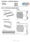
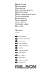
The 7303 is a general purpose, control panel card with data input and display capability (Fig. 1-1). It includes
an 8-position alphanumeric display keyboard with 24 program-definable keys plus system reset, an .8-bit
binary LED display, and two rocker switches. (See Fig. 1-2 for the block diagram.)
You can use the 7303 in applications where you need a low cost interface for system control, data entry, status
display, and operator prompting. Also, the card is useful for system development, testing, and training
applications.
The 7303 can be mounted in the first position in a card cage with an open-end panel, on a card extender such
as the 7901, or on a 1/8-in. thick panel.
Main Features of the 7303 are:
•
•
•
•
•
•
•
•
8-position alphanumeric display with ASCII input
24 programmable keys plus reset
Repairable keyboard and replaceable key labels
8-bit binary LED display
2 rocker switches
Simple program control of displays and keys
On-card I/O ports for processor control
Single +5V Operation
o
o
Figure 1-1. 7303 Keyboard/Display Card.
1-1
~
I
I\)
SW2n
\
DATA BUS
07 - DO
Q
JQ
/
'8
DATA
BUS
BUFFERS
vi
j
/
....
SW1n
ROCKER
SWITCHES
'7
I
78
CONTROL
PORT
LATCHES
r\..
/
eee~~~~~
/
~
/4
EIGHT -CHARACTER
ALPHANUMERIC
DISPLAY
~
CONTROL
DATA
'4
~~
10EXP
)
ADDRESS BUS
A7 - AO
\
,;
III!!!II
II
CARD
&
PORT
SELECT
LOGIC
I 7
II
16
••••••••
EIGHT INDICATORS
/
'8
V
DATA
PORT
LATCHES
~
/
Is
/
~
/
"
18
j
I
I 4
COLUMN SELECT
~
10RQ*
RD*
WR*
1/0
CONTROL
LOGIC
&
BUFFERS
.
15
16
17
[lli]
C
0
E
F
13
e
9
A
B
12
4
5
6
7
11
0
1
2
3
10
SET
KEYBOARD
MATRIX
SYSRESET*
PBRESET*
14
ROW READ
RESET KEY
~
./
--.
....
-
--
* Active low level logic
Figure 1-2. Block Diagram of the 7303 Keyboard/Display Card.'
o
c
~
o
.... ~~L... "-
~c-
SECTI'ON 2
Installation and Specifications
o
The 7303 operates as part of an STD BUS card rack system. You can plug it directly into the STD BUS
backplane (Fig. 2-1) or extend it from the motherboard with a 7901 card extender, or equivalent. In this
configuration, the card is mapped at processor I/O port addresses.
Insert the card in the left-most socket (viewed from the card ejector end of the rack) of a card cage that has the
left end plate open.
Insert a 7901 card extender in any card slot and plug the 7303 into the card extender. In this position, the 7303
clears the other cards and is accessible.
If you mount the 7303 remotely from the card rack, you will need buffering between the card rack and the 7303.
A suitable method is to operate the card as an I/O load driven by input and output ports, rather than as an I/O
mapped processor-backplane load. For more information, see Pro-Log's Application Note PLAN 131
(Appendix A).
I/O Mapped Card Addressing
In its normal operation, the 7303 is addressed directly by the processor card. The 7303's input and output ports
respond to single read and write instructions executed in the processor's operating program. The 7303 is
enabled when a jumper-selected combination of address lines AO through A7 is present, and when the
following control lines are active: 10RQ*, 10EXP, and either RD* or WR*.
o
The 7303 occupies two consecutive I/O addresses regardless of its mapping assignment. The card is shipped
with the control port mapped at D1 and the data port mapped at DO. You may retain these addresses or change
them by moving the installed jumper wires. By using DO and D1, the preferred addresses, you can easily adapt
standard Pro-Log software. While the card's port addresses are generally arbitrary, they must differ from all
other I/O port addresses in the system. If they do not differ, multiple cards will respond to the same READ
instruction, resulting in BUS contention.
7800 SERIES
CPU CARD
STD BUS
7303
KEYBOARD/DISPLAY
CARD
o
Figure 2-1. 1/0 Mapped Operation In Local Card Rack.
2-1
-
........._ _ _ G.Iki!&lWiWiIJiW";;. . .=iJ;..J&m..iA,MMAAMIlMi14&aiWi6aalU&kl&;g,;u;;JA,,lUdJM gn '-_ .M 21.00;; " iF
"r"Q
Changing the Port Addresses
Locate decoders U3, U4, and US (74LS42) next to the STD BUS edge connector. Each decoder device has a
dual row of pads that form decoder output select matrices. Make one (and only one) connection to each of the
matrices next to U3 and U4, and two connections next to US.
The decoder pad numbering (Fig. 2-2) shows the numbering ofthe pads nextto the decoder chips on the 7303.
Also shown are the jumpers (at X6, Y4, ZO, Zl) that produce the hexadecimal port address DO and D1, the
selection made when the card is shipped.
The 1/0 address mapping and jumper selection for two addresses per card is shown in Figs. 2-3 and 2-4. It
indicates where to place jumperstraps to obtain any port address in theOO-FF hexadecimal range. Using the 2digit hexadecimal port addresses desired, find the hexadecimal port addresses along the vertical axis, and
read the corresponding strap positions from Fig. 2-4. For example, port address DO and D1 are obtained by
connecting jumpers at X6, Y4,ZO, and Zl. This is the preferred address and isshown on the table by the shaded
area.
0
0
)
20
)
10
11
U2
74LS240
1
+
:1
11
Ul
74LS244
1
C1
.\
loc401
20
1
,
J
10
J.
1.,
U3
0
8
0
I/)
U
74LS42
1
9
o
0000008°sx
000000 0
o 1 2 3 4 5 6 7
~
1.,
9
U4
74LS42
1
8
00008000sy
0000 000
01234567
1.,
us
:II
74LS42
1
sz
8888
o
~
1 2 3
14
1
~~
o )
55
8
U6
74LS32
.1'1
U7
74LS244
1
7
n
-nr
11
10
0
Figure 2-2. Decoder Pad Numbering for the 7303.
o
2-2
Jj
J
CARD 5ELECT DECODER5
0
12
0
U3
74L542
57
5X&
56
':"
A7
15
A6
17
13 C
53
14 B
52
51
A5
15 A
19
50
57
SV&
S6
A4
13 C
21
S5
S4
S3
A3
23
A2
25
14 B
S2
S1
15 A
SO
PORT SELECT DECODER
13
14
C
0
SZ&
':"
A1
27
AO
29
74LS32
53
14 B
52
S1
15 A
SO
16
U7
18
':"
74LS244
Figure 2-3. 7303 1/0 Address Decoder and Schematic for 2 Addresses Per Card
(shown mapped at 00 and 01, the preferred card address).
o
2-3
WJJtIIhGiMMi..-.w:tWWW&iMlMIGiWil'GliMm", 1iiiM!iWIbUi'Mt;tMiMLhd;1&%&i!f;;;;.&M1hMl\&AiM"i_l'M1f1iiMtMK;:;H,;,~m;li!9J+
PORTS
00
01
02
03
04
05
06
07
08
09
OA
OB
OC
00
OE
OF
10
11
12
13
14
15
16
17
18
19
1A
1B
1C
10
1E
1F
20
21
22
23
24
25
26
27
28
29
2A
2B
2C
20
2E
2F
30
31
32
33
34
35
36
37
38
39
3A
3B
3C
3D
3E
3F
JUMPER WIRES
XO, YO, ZO, Z1 XO, YO, Z2, Z3 XO, Y1,ZO.Z1XO. Y1, Z2, Z3XO, Y2, ZO, Z1 XO, Y2, Z2. Z3 XO, Y3, ZO, Z1 XO, Y3, Z2, Z3 XO, Y4, ZO, Z1 XO, Y4, Z2, Z3 XO, Y5, ZO, Z1 XO, Y5, Z2, Z3 XO, Y6, ZO, Z1 XO, Y6, Z2, Z3XO, Y7, ZO, Z1 XO, Y7, Z2, Z3X1, YO, ZO, Z1X1, YO, Z2, Z3X1, Y1, ZO, Z1 X1, Y1, Z2, Z3 X1, Y2, ZO, Z1 X1, Y2, Z2, Z3X1, Y3, ZO, Z1 X1, Y3, Z2, Z3X1, Y4., ZO, Z1X1, Y4, Z2, Z3X1, Y5, ZO, Z1 X1, Y5, Z2, Z3X1, Y6, ZO, Z1 X1, Y6, Z2, Z3X1, Y7, ZO, Z1 X 1, Y7, Z2, Z3 -
PORTS
40
41
42
43
44
45
46
47
48
49
4A
4B
4C
40
4E
4F
50
51
52
53
54
55
56
57
58
59
SA
5B
5C
50
5E
5F
60
61
62
63
64
65
66
67
68
69
6A
68
6C
60
6E
6F
70
71
72
73
74
75
76
77
78
79
7A
78
7C
70
7E
7F
JUMPER WIRES
X2, YO, ZO, Z1X2, YO, Z2, Z3X2. Y1, ZO, Z1-
X2, Y1, Z2, Z3X2, Y2, ZO, Z1 X2. Y2, Z2, Z3-
X2. Y3, ZOo Z1 X2, Y3. Z2, Z3-
X2. Y4. ZO, Z1 X2. Y4. Z2, Z3X2. Y5. ZOo Z1 X2, Y5, Z2, Z3X2, Y6, ZO, Z1 X2, Y6, Z2, Z3X2, Y7, ZO, Z1X2, Y7, Z2, Z3X3, YO, ZO, Z1 X3, YO, Z2, Z3 X3, Y1, ZO, Z1 X3, Y1, Z2, Z3X3, Y2,ZO,Z1X3, Y2, Z2, Z3X3, Y3,ZO, Z1X3, Y3, Z2, Z3X3, Y4, ZO, Z1X3, Y4,Z2,Z3X3, Y5,ZO, Z1X3, Y5, Z2, Z3X3, Y6,ZO,Z1X3, Y6,Z2,Z3X3, Y7,ZO,Z1X3, Y7, Z2, Z3-
PORTS
80
81
82
83
84
85
86
87
88
89
8A
8B
8C
80
8E
8F
90
91
92
93
94
95
96
97
98
99
9A
9B
9C
90
9E
9F
AO
A1
A2
A3
A4
AS
A6
A7
A8
A9
AA
AB
AC
AD
AE
AF
BO
B1
B2
B3
B4
B5
B6
B7
B8
B9
BA
BB
BC
BO
BE
BF
JUMPER WIRES
X4, YO, ZO, Z1X4, YO, Z2, Z3-
X4, Y1, ZO, Z1 X4, Y1, Z2, Z3X4, Y2,ZO, Z1-
X4. Y2, Z2, Z3X4, Y3, ZO, Z1 X4, Y3. Z2, Z3X4, Y4. ZO, Z1 X4. Y4, Z2. Z3X4. Y5, ZOo Z1 X4. Y5, Z2, Z3X4, Y6,ZO. Z1X4, Y6, Z2, Z3-
X4, Y7, ZO, Z1X4, Y7, Z2, Z3X5, YO,ZO, Z1X5, YO, Z2, Z3X5, Y1,ZO, Z1X5, Y1, Z2, Z3X5, Y2,ZO, Z1X5, Y2, Z2, Z3X5, Y3,ZO, Z1X5, Y3,Z2,Z3X5, Y4,ZO, Z1X5, Y4, Z2, Z3X5, Y5,ZO, Z1
X5, Y5,Z2, Z3X5, Y6,ZO, Z1X5, Y6,Z2, Z3X5, Y7, ZO, Z1X5, Y7,Z2,Z3-
PORTS
CO
C1
C2
C3
C4
C5
C6
C7
C8
C9
CA
CB
CC
CO
CE
CF
DO
01
02
03
04
05
06
07
08
09
OA
DB
DC
DO
DE
OF
EO
E1
E2
E3
E4
E5
E6
E7
E8
E9
EA
EB
EC
ED
EE
EF
FO
F1
F2
F3
F4
F5
F6
F7
F8
F9
FA
FB
FC
FO
FE
FF
JUMPER WIRES
X6, YO, ZO, Z1-
X6, YO,Z2, Z3X6, Y1, ZO,Z1X6, Y1,Z2, Z3X6, Y2,ZO,Z1X6, Y2, Z2,Z3X6, Y3, ZO, Z1X6, Y3, Z2, Z3rt!;"'i!i!;};'!'
,';!,
'!!fi!!! ~
i!t,,;'?;;,;;,;;;!,,!!;:,' ,',",;nIJ;,"2 fj,;;!,
X6, Y4, Z2, Z3X6, Y5, ZO, Z1X6, Y5, Z2,Z3X6, Y6, ZO, Z1X6, Y6, Z2, Z3X6, Y7, ZO,Z1X6, Y7,Z2,Z3X7, YO, ZO,Z1X7, YO, Z2, Z3-
2-4
o
X7, Y1,ZO,Z1X7, Y1, Z2,Z3X7, Y2,ZO,Z1X7, Y2,Z2,Z3X7, Y3, ZO,Z1X7, Y3,Z2,Z3-
X7, Y4,ZO,Z1X7, Y4, Z2,Z3X7, Y5,ZO,Z1X7, Y5,Z2,Z3-
X7, Y6, ZO,Z1X7, Y6,Z2,Z3X7, Y7,ZO,Z1X7, Y7,Z2,Z3-
Shading denotes as-shipped configuration.
Figure 2-4. Jumpers Required for 7303 Port Address Mapping.
o
o
o
The jumpers installed at the time of manufacture may be removed and installed at different locations, implementing different port addresses. The preferred method of removing jumpers that have been soldered to the
board is to first cut the jumper in half, then unsolder each half individually and discard. Remaining solder
should then be removed from the holesand new jumpers installed atthe appropriate locations.
NOTE
On some early 7303 cards, circuit traces were used instead of wire jumpers to implement ports DO and
01. In such cases, cutthe jumper trace and remove itfrom the board with a sharp knife, taking care not
to damage the board or any other traces; then proceed to install the new jumper(s).
Alternatives to Soldered Wire Jumpers
If occasional or frequent changes in address mapping jumpers are anticipated, remove the wire jumpers and
populate the jumper pads with 0.025-in. sq uare posts, which are available,Jndividually and in single and double
strips corresponding to the 0.100-in. gri djumper pad spacing on the card. The posts may then be connected by
wirewrap or by jumper clips available from several sources. Check the height above the board that these parts
may protrude, in order to avoid interference with adjacent cards. The recommended wirewrap square post for
SX and SY is AMP No. 87215-5, or equivalent. For SZ, it is AMP No. 87215-1, orequivalent. The recommended
jump clip is AMP No. 530153-2, or equivalent.
Electrical and Environmental Speclficatl()ns
RECOMMENDED OPERATING LIMITS
o
SYMBOL
PARAMETER
ABSOLUTE NONOPERATING LIMITS
MIN
TYP
MAX
MIN
MAX
UNIT
4.75
5.00
5.25
0.0
5.50
V
25
55
0
55
°C
95
0
95
%RH
Vee
Supply voltage
TA
Free air temperature
0
RH
Humidity a
5
a Noncondensing.
Figure 2-5. Electrical Specifications - 7303 Keyboard/Display Card.
PARAMETER
SYMBOL
MIN
TYP
MAX
UNIT
300
500
rnA
Icc
STD BUS supply currenta
-
STD BUS input load
See Fig. 2-7
See rig. 2-7
-
STD BUS output drive
se~ Fig. 2-7
See ;Fi9. 2-7
l
a All segments driven.
Figure 2-6. STD BUS Electrical Characteristics over Recommended Operating Limits.
o
2-5
PIN NUMBER
PIN NUMBER
OUTPUT (LSTTL DRIVE)
OUTPUT (LSTTL DRIVE)
INPUT (LSTTL LOADS)
INPUT (LSTTL LOADS)
MNEMONIC·
MNEMONIC
+5V
VCC
2
GROUND
GND
-5V
1
VCC
4
3
GND
6
5
+5V
GROUND
-5V
D7
1
55
8
7
55
1
D3
D6
1
55
10
55
1
D2
D5
1
55
12
9
11
55
1
D1
D4
1
55
14
13
55
1
DO
A15
16
15
1
A7
A14
18
1
A6
A13
20
17
19
1
A5
A12
22
21
1
A4
A11
24
23
1
A3
A10
26
25
1
A2
A9
28
1
A1
30
27
29
1
AO
32
31
1
WR*
MEMRQ*
34
33
1
MEMEX
36
35
1
IORQ*
IOEXP
MCSYNC*
38
37
REFRESH*
STATUS 0*
40
39
STATUS 1*
A8
1
RD*
BUSRQ*
42
41
BUSAK*
INTRQ*
44
43
INTAK*
46
48
45
47
50
49
NMIRQ*
OUT
PBRESET*
CNTRL*
IN
PCI
AUX GND
AUX
-v
o
WAITRQ*
1
SYSRESET*
CLOCK*
OUT
52
51
54
53
PCO
AUX GND
56
55
AUX +V
• Active low-level logic
Figure 2-7. Edge Connector Pins for the 7303.
Figure 2-8 shows the timing requirements that must be observed by the 7303's operating software. T81 and T 82
define the uncertainty period for input port data after a mechanical key or switch opens or closes. Figure 2-9
defines the other data parameters listed below.
SYMBOL
PARAMETER
t'B1
Key bounce
tB2
Rocker bounce
tlS1
Data setup
FROM
Key depressed or
released
Switch closed or
opened
ASCII data
t'S2
Write setup
tw
t'H
TO
MAX
UNIT
Key data stable
15
ms
Swi1ch data stable
15
ms
MIN
Position pulse
1.2
,."s
Position address
Write pulse
0.6
,."s
Write width
Write pulse active
Wri1e pulse inactive
1.1
,."s
Write hold
Write pulse
I nvalid data
address
0.5
,."s
Figure 2-8. Switching Characteristics over Recommended Operating limits-7303 Card.
2-6
o
0
/~
DATA
ADDRESS
ASCII CHARACTER VALID
~Y
WRITE
DISPLAY POSITION
ADDRESS VALID
tH
WRITE ACTIVE • " "
tw
Figure 2-9. 7303 Alphanumeric Display Timing Waveforms.
(Note: Waveforms illustrate program values. WRITE is low level active in hardware.)
Mechanical Specifications
The 7303's storage and nonoperating temperature range is limited to 0 to 55°C.
The 7303 meets all general mechanical specifications of the STD BUS except for component height, which is
0.95 in. (2.14 cm) maximum. If you use the 7303 as an interface card, install it in one of two ways that allow you
access to the component side of the card, utilizing a single slot in the card rack.
SYMBOL
-
o
PARAMETER
Key life expectancy
Component height
MIN
TYP
MAX
UNIT
Operations
3x10 6
0.95
in.
Figure 2-10. Mechanical Characteristics over Recommended Operating Limits-7303 Card.
o
2-7
_ _ _ _ 'W&IIiII&JiL---
o
o
I,
I
o
2-8
SECTION 3
Operation and Programming
o
The 7303, as a general-purpose control panel card, operates as part of the STD BUS card rack system. You
can use the 7303 for system control, data entry, status display, and operator prompting in low-cost interface
applications. The 7303 can also be used for system development, testing, and training.
The 7303's operator interface consists of an a-position alphanumeric display; 24 program-definable keys plus
a fixed-function reset key that resets the systems's processor card; an a-bit binary LED display; and two
rocker switches. This section shows how each of these elements works and how they are programmed. Actual
program examples are found in Section 4.
Figure 3-1 shows the physical layout of the 7303's switches and indicators. It also shows the display position
numbers (7-0), the numeric values of the keys in hexadecimal (0-17), and the rocker switch numbers (S1 and
S2). These designations are important when programming the 7303, and you will probably want to refer back
to Fig. 3-1 while reading the rest of this section.
----ALPHANUMERiC DISPLAY - - LEFT
o
ROCKER
SWITCH
LEFT HALF
RIGHT HALF
RIGHT
ROCKER
SWITCH
•
~
- - - - - - L E D DISPLAY-----
GGGGEJ
GG08G
~~8~G
8088G
80080
-----KEYBOARD---------
o
Figure 3-1. 7303 Keyboard/Display.
3-1
..__._...... - ...•_.. _... _._.._....
----------_._-_ .. _ - - - - - - - _ . - .. _
_-._ .......__.._._.__._ .._....................
~.-.~
...
..-......-
-~~
Alphanumeric Display
The display consists of eight, 16-segment alphanumeric positions. Each position displays any characterfrom
the 64-character ASCII set. It can also display a cursor character (all segments on). Each display position has
an ASCII character memory and a separate cursor memory. These separate memories allow the cursor to be
displayed and removed without altering the ASCII character memory. Each display position is randomly
addressable.
o
Two onboard output ports drive the display (Fig. 3-2). The display's operation is controlled by program
manipulation of the output bits from these ports. The ports provide the display with data, addressing, and
control signals, giving the program random access to any of the eight display positions.
You can program each display position in either of two modes: character or cursor. 8yflashing the cursor (all
segments on) alternately with another character, you can draw attention to one or more of the display
positions. Also, you can use the cursor as a lamp test. The display can have any combination of characters and
cursors present.
In the character display mode, you can load each display position with any of the characters shown in Fig. 3-3.
Use the SPACE character to blank the position. Note that the display uses 7-bit ASCII code. Each display
position has its own ASCII character memory, ASCII-to-16-segment decoder, and lamp drivers.
In the cursor display mode, each display position can show the cursor character, and each position has a
separate cursor memory in addition to its character memory. Since setting the cursor-on memory bit does not
alter the content of the ASCII character memory, you can flash the cursor and an ASCII character alternately
by setting and clearing the cursor memory.
The functions of the two onboard output ports differ between character display mode and cursor display mode
(including display clearing). We discuss these two modes separately; also we provide separate subroutine
modules for the 7303's alphanumeric display operation in each mode (see Section 4).
.~
0
.1,11
,I
II
RIGHT HALF
LEFT HALF
.:!,
POSITION
SELECT
WR
CONTROL PORT
d7
MODE
SELECT
ASCII
INPUT
DATA PORT
d7
OUTPUT
PORT
ADDRESS
01
-WR
A2
A1
OUTPUT
PORT
ADDRESS
DO
AO
dO-d7
Figure 3-2. Alphanumeric Display Programming Model for the 7303.
3-2
o
o
ASCII
CHAR
HEX
CODE
ASCII
CHAR
HEX
CODe
ASCII
CHAR
HEX
CODE
ASCII
CHAR
HEX
CODE
SPACE
!
AO
A1
A2
A3
A4
A5
A6
A7
A8
A9
AA
AB
AC
AO
AE
AF
0
1
2
3
4
5
6
7
8
BO
B1
B2
B3
B4
B5
B6
B7
B8
B9
SA
BB
BC
BO
BE
BF
@
CO
C1
C2
C3
C4
C5
C6
C7
C8
C9
CA
CB
CC
CO
CE
CF
P
00
01
02
03
04
05
06
07
08
09
OA
OB
OC
00
OE
OF
"
#
$
%
&
,
(
)
*
+
,
.
/
9
··
·,
<
=
>
?
A
B
C
D
E
F
G
H
I
J
K
L
M
N
0
Q
R
S
T
U
V
W
X
Y
Z
[
\
]
A
-
(Note)
Note: Underscore.
Figure 3-3.
o
Hexadecimal Values of ASCII Characters.
Initialization: Reset Characteristics. The 7303's SYSRESET* input clears its output ports but does not clear
the alphanumeric display or its character and cursor memories. If SYSRESET* occurs while the program is
changing the content of the alphanumeric display, the content may be altered unpredictably. Therefore, make
sure you restore or clear the alphanumeric display after a system reset.
Also, after power-on, the display's content is unpredictable. So initialization by a programmed instruction
sequence is generally needed soon after power-on. To blank the display, load the SPACE character (ASCII
Ihexadecimal AO) in each display position. Note that a separate instruction sequence is required to clear the
cursors.
ASCII Character Set. The 7303 can display 64 different characters. These characters, and the hexadecimal
code to produce each one, are given in Fig. 3-3.
To use this figure, identify the character you wish displayed. The code to the right of the character is a tWO-digit
hexadecimal number that uniquely identifies the character. Forthe 64 characters that the 7303 can display, the
codes range from AO through OF. For example: the hexadecimal code for the SPACE character is AO, for the
number 3 it is B3, and for the letter M it is CO.
The use of hexagecimal codes not listed in the figure results in either a blanked display position (if bit 7 of the
code is 1), or undefined cursor activity (if bit 7 is 0).
NOTE on Port Addresses
Section 2 shows how you can remap the 7303's address decoders to allow the card to occupy any
two consecutive port addresses in the OO-FF hexadecimal range.
The 7303 is shipped with port addresses 00 and 01 selected by jumper wires, and all of the
explanation of the card's operation and programming in this section assumes that these addresses
remain connected.
o
If you elect to remap the 7303, regard the onboard ports as the Oata Port and the Control Port (ports
00 and 01, respectively).
3-3
H SW¥%¥\¥
Output Port Bit Assignments for Character Mode
Data Port. Output port DO selects character mode (bit 7 = 1) and specifies one of the 64 ASCII characters to be
displayed in bits 0-6. Figure 3-4 shows the bit assignments in the data port for character mode.
DATA BUS
MNEM
DESCRIPTION
d7
MODE
1 = Character mode
d6
b6
MSB
d5
bS
d4
b4
d3
b3
d2
b2
d1
b1
dO
bO
0
1
1
7-bit ASCII character
LSB
Note: Standard data port address is HEX DO.
Figure 3-4. Data Port Bit Assignments for Character Mode-7303 Card.
Control Port. Output Port D1 selects the alphanumeric display position address (bits 2, 1,0) and enables the
display's WRITE function as shown in Fig. 3-S.
,I
!I
I
DATA BUS
MNEM
d7
X
d6
X
d5
X
d4
X
d3
WR
d2
A2
d1
A1
dO
AO
~
DESCRIPTION
0
Don't care
1 = Write, 0
= Write
inhibit
Display position address 0-7
See Fig. 3-6
Note: Standard control port address is HEX D1.
Figure 3-5. Control Port Bit Assignments for Character Mode-7303 Card.
Figure 3-6 shows the bit patterns required in the control port's bits 2, 1,0 to address the eight alphanumeric
display positions 0-7.
DATA BUS
DISPLAY POSITION
MNEM
7
6
5
4
3
2
1
0
d2
A2
1
1
1
1
0
0
0
0
d1
A1
1
1
0
0
1
1
0
0
dO
AO
1
0
1
0
1
0
1
0
Figure 3-6. Display Position Addressing-7303 Card.
3-4
o
:'11
I
o
Programming In the Character Display Mode. Causing one of the ASCII characters to appear in one of the
7303's display positions requires four steps in the program. These four steps can be summarized as follows:
1. Output the hexadecimal value of the ASCII character to be displayed (Fig. 3-3) to the 7303's data
port (Fig. 3-4).
2. Output the 3-bit address of the display position the character is to occupy (7-0) with the write
bit = 0 to the control port (Fig. 3-5).
3. Repeat step 2, but set the write bit = 1.
4. Repeat step 2 (write bit returns to zero, protecting the display).
These steps are summarized as a flow diagram and resulting waveforms in Figs. 3-7 and 3-8 below.
STEP 1
WRITE CHARACTER CODE TO
DATA PORT
STEP 2
WRITE POSITION
ADDRESS WITH
WR=OTO
CONTROL PORT
Find program values in Fig. 3-3.
DISPLA Y POSITION
PROGRAM STEP
STEP 3
0
STEP 4
WRITE POSITION
ADDRESS WITH
WR=1 TO
CONTROL PORT
WRITE POSITION
ADDRESS WITH
WR=OTO
CONTROL PORT
7
6
5
4
3
2
1
°
COMMENT
Step 2
07 06 05 04 03 02 01 00
Write
=
Step 3
OF OE 00 OC OB OA 09 08
Write
=
1
Step 4
07 06 05 04 03 02 01 00
Write
=
0
0
Program Values for Steps 2, 3, 4.
Figure 3-7. Flow Diagram of Character Mode Events for the 7303.
STEP 1
I
DATA
PORT
bO-b6
=X~
___
C_H_A_R_A_C_T_E_R_C_O_D_E_V_A_L_ID_ _ _ _> < =
I
A2.A1.AO _ _ _ _
CONTROL
PORT
STEP 2
STEP 3
I
i
i
!
!
. STEP 4
~~~~_ _P_O_S_IT_I~O-N-A-D-D-R-E-S-S-V-A-LI~D_~><=
I
WR 1
[
WRITE _ _ _ _ _ _ _-'--_ _
W_R_O.;..;/.
o
ACTIVE
~WR °
Figure 3-8. Character Mode Timing Waveforms for the 7303.
(Note: Waveforms illustrate program values. WR is low ~ctive in hardware.)
3-5
&G_fAlliMiii"UJiGDia&W4U111ii8;;m&&AiiiiI&WMi=====aom==,jUMtUID#_M3,MiiJiiIAbAWn#Mt "Pit
I
"Ai,; ;; hi ;,,;:rMliki;;«;.jj k;;
I
;.
.\MF.4fflI1iT?¥%
Cursor Mode
Once a valid ASCII character is loaded into the display position's ASCII memory, the position can display the
cursor character. Note that ASCII characters must be displayed before the cursor can be displayed; the
SPACE character satisfies this requirement.
o
'
',1',
I
1'~
~
I
Output Port Bit Assignments for Cursor Mode
Cursor mode and character mode share the same output ports, but the bit functions differ between the two
modes.
Data port. Output port DO sel~cts cursor mode (bit 7 = 0). Bits 0,1,2,3 specify the cursor on/off state for four
display positions at a time. Eitt\erthe right half of the displays (positions 0,1,2,3) orthe left-half ofthe displays
(positions 4, 5, 6, 7) can be addressed in one operation. Figure 3-9 shows the data port bit assignments for
cursor mode.
DATA BUS
MNEM
DESCRIPTION
d7
MODE
o = Cursor mode
d6
b6
d5
b5
d4
b4
d3
b3
Cursor enable, positions 3 and 7
d2
b2
Cursor enable, positions 2 and 6
d1
b1
Cursor enable, positions 1 and 5
dO
bO
Cursor enable, positions 0 and 4
Don't care
Set bit = 1 to
display cursor.
Reset bit = a to
remove cursor.
Note: Standard data port address is HEX DO.
Figure 3-9. Data Port Bit Assignments for Cursor Mode-7303 Card.
Control Port. .output port 01 controls the display's WRITE function (Fig. 3-10) and selects between the righthand four displays and the left-hand four displays (Figs. 3-10 and 3-11).
DATA BUS
MNEM
DESCRIPTION
d7
X
d6
X
dS
X
DISPLAY
d4
X
POSITION
7
d3
WR
DATA BIT
B3
d2
A2
d1
A1
dO
AO
Don't care
1
= Write;
0
= Write inhibit
1 = Left-half select (positions 7, 6, 5, 4)
o = Right-half select
A2
LEFT HALF
I 6 I5 I 4
I B2 I B 1 I BO
1
RIGHT HALF
3
B3
I2 I1 I
0
(positions 3, 2, 1, 0)
Don't care
Note: Standard control port address is HEX 01.
Figure 3-10. Control Port Bit
Assignments for Cursor Mode-7303 Card.
3-6
0
I B2 I B1 I BO
Figure 3-11. Left/Right Display Position
Group Select for Cursor Mode-7303 Card.
o
Programming in the Cursor Display Mode. With a valid ASCII character loaded to a display position, the cursor
character can also be displayed in that position. When the cursor is removed, the same ASCII character will
reappear.
Cursor characters can be turned on or off in any combination, in groups of four display positions (right half =
positions 0, 1, 2, 3 and left half = positions 4, 5, 6,7). Controlling all eight cursors requires two sepa'rate
operations.
Setting/clearing the left-half or right-half cursor memories requires four steps in the program:
1. Output the desired states of four of the cursors to the data port (Fig. 3-9).
2. Output the left/right select bit with write
= 0 to the control
port (Fig. 3-10).
3. Repeat step 2, but set the write bit = 1.
4. Repeat step 2 (write bit returns to zero, protecting the display).
These steps are summarized as a flow diagram and resulting waveforms in Figs. 3-12 and 3-13 below.
STEP 1
WRITE 4 CURSOR
STATES TO
DATA PORT
STEP 2
WRITE CONTROL
PORT SELECTING
LEFT/RIGHT
DISPLAYS AND WR=O
DISPLAY POSITION
0
LEFT HALF RIGHT HALF
PROGRAM STEP
WRITE CONTROL
PORT SELECTING
LEFT/RIGHT
DISPLAYS AND WR=1
STEP 3
04
00
Write - 0
Step 3
OC
08
Write - 1
Step 4
04
00
Write
=0
Program Values for Steps 2, 3, 4.
WRITE CONTROL
PORT SELECTING
LEFT/RIGHT
DISPLAYS AND WR=O
STEP 4
COMMENT
Step 2
Figure 3-12. Flow Diagram of Cursor Mode Events for the 7303.
><=
STEP 1
I
~~~~
bO-b3
==>K___
4_-_B_IT_C_U_R_S_O_R_P_A_T_T_E_R_N_V_A_L_ID_ _ _
I
STEP 2
STEP 3
I
I
STEP 4
____,,...---------:----vI
RIGHT~O _ _ _ _ _ _,.J'V'I
~_
A2 (UR SELECT) VALID
LEFT=1
"--_ _ _
CONTROL! A2
PORT
I
I
I
WRITE _ _ _ _ _ _ _"--_ _W_R_=O,.J/,
o
~
WR=1
ACTIVE
I
~WR=O
Figure 3-13. Cursor Mode Timing Waveforms for the 7303.
(Note: Waveforms illustrate program values. WR is low active in hardware.)
3-7
~
.1
·:1
Keyboard
The keyboard consists of a RESET key and 24 program-definable keys (Fig. 3-14).
The RESET key is not programmable. When pressed, it grounds the 7303's PBRESET* output to the STD BUS
backplane. This signal is provided to reset the system processor card, which responds by generating
SYSRESET*. SYSRESET* is an input to the 7303 card, which resets the 7303's output ports. The exact
characteristics of the SYSRESET* signal depend on the processor card in use.
o
The 24 program-definable keys are wired in a 4 x 6 switch matrix. The four columns (vertical axis) are driven by
the data port (output DO port bits 0,1,2,3) and the six rows (horizontal axis) are sensed by input port DO bits 0,
1,2,3,4,5.
Reading the keyboard is a programmed operation. The program strobes each column of keys in turn, using
rotate or shift instructions to move the strobe (a logic "1") from column to column. As each column is strobed,
the program reads the input port to see if a switch closure has connected the strobe bit to the input port. If so,
both key coordinates are now known (the program generated the column value and the input port read the row
value), so thatthe value of the key can be computed. If not, the program steps the strobe to the next column and
repeats the process until a key closure occurs.
14
15
16
-17
~
C
0
E
F
13
8
9
A
B
12
4
5
6
7
11
0
1
2
3
10
SET
Physical Layout
Figure 3-14. Keyboard Programming Model for the 7303.
3-8
o
o
Key Values. The value assigned to a key is an arbitrary, unique identifier that can be derived once the column
and row coordinates are known. The (DECODE.KEY) subroutine provided in the 7303's software package in
Section 4 uses an algorithm that identifies each key with a hexadecimal number in the 00-17 range. The 7303 is
shipped with key labels that show the value that will be generated by the (DECODE.KEY) subroutine when the
key is pressed.
Frequently, the value associated with a key is meaningless in relation to the application, and the user may wish
to rename the key with a more meaningful label. The generalized (DECODE.KEY) subroutine is still used to
locate a key closure, but the value returned is decoded a second time to lead to a specific system function. For
example, the CALCULATOR program example in Section 4 shows how to use the compare and conditional
jump instructions to detect the "11" key and assign it the "CLEAR DISPLAY" system function.
Key Reading Procedures. In addition to simply detecting and decoding a key closure, the program may also be
responsible for the following key-control procedures:
1. Differentiate between noise and a genuine key closure.
2. Ignore key-contact bounce when a key closes or opens.
3. React only when the key closes, not when it opens (or vice versa).
4. Avoid multiple responses to the same closure.
Noise and key-contact bounce can be suppressed by programming a double READ with a time delay between
the READs as shown in Fig. 3-15.
SCAN
KEYBOARD
o
DETECT
KEY
SAVE KEY
COORDINATES
REJECT
AS
ACCEPT
KEY
DETECT
KEY
CTREDE~AY ~r
&
DECODE
CLor DELAY
:::-----v~----------------------~~~
TIME DELAY
'15ms FOR
SWITCH BOUNCE
____~_
Voltage Waveform at Row In Key Matrix
DECODE
THE
KEY
Example of Program Flow
o
Figure 3-15. Programming Key. Bounce and Noise Rejection for the 7303.
(Note: This figure illustrates the technique of read/delay/re-read/compare, which allows the
program to differentiate between noise and a legitimate key closure, and to pause while the key
contacts settle.)
3-9
-====......
MM4D&aw:nwwN&&&AIMWi&Mfi,4iMiiM¢ ,;.uiA
,u,
;;U;;;$
4,;
;.fi\PfflI¥tiITfMii
¥G
In most instances, it is desirable for the key to be effective when pressed, not when released. Because of the
speed of microprocessors, there is also a real possibility that the system might react more than once to the
same key closure before the operator can remove his finger (with practice, an operator can deliberately close
and release a small pushbutton in about 50ms; however, this represents an absolute minimum and the
program should not make assumptions about the operator's characteristics).
o
The (READ.KEY) subroutine in Section 4 shows how to combine the key decode process with procedural
controls to produce reliable, error-free keyboard entries.
,
I
The basic assumption in the (READ.KEY) routine is that when the subroutine is entered, the operator's finger is
still on the key that was just decoded. The software waits until the operator releases the previous key, then
waits again until he presses the next key, then decodes the next key. This technique ensures two important
characteristics:
II
II
'I
1. The system will react one and only one time to one key closure.
2. The system's reaction will take place immediately after the key is closed and not when it is
released.
Figure 3-16 shows a flow diagram of the major events during the (READ.KEY) subroutine.
(READ, KEY)
n
"
YES
0
:,
I
i:
NO
YES
DECODE
NEW KEY
EXIT
Figure 3-16. Recommended System-Level Keyboard Procedure for the 7303.
(Note: Contact bounce and noise rejection are not shown.)
3-10
o
Binary LED Display
o
The 8-bit binary LED display (Fig. 3-17) is driven directly by output data port ~O-the same output port that
strobes the keyboard and supplies ASCII data to the alphanumeric display. When a bit from this port is in the
high state, the corresponding LED lights up. The LED display is cleared by the SYSRESET* input.
Because output data port DO is used in both alphanumeric display and keyboard decoding operations, the
binary LEOs change when you address either the display or keyboard. The binary LEOs are useful in training,
or in developing programs for the alphanumeric display and keyboard.
You can also use the binary LEOs to display data that is unrelated to the alphanumeric display and keyboard,
but when you do:
.
1. Refresh the binary LED display after any keyboard scan or alphanumeric display operation.
2. Note that the binary LEOs will show dynamic keyboard-scanning activity for as long as a
keyboard key is depressed (using the subroutine in Section 4).
3. Do not output binary display information to the LEOs, unless the alphanumeric display's WRITE
bit (output port 01, bit 3) is first set to the "0" state to inhibit changes in alphanumeric display.
+5V
DATA PORT
OUTPUT
PORT
ADDRESS
7
DO
o
b7*
6
b6*
5
b5*
4
b4*
3
b3*
2
b2*
0
b1*
bO*
*Low Level Active
Figure 3-17. Binary LED Display for the 7303.
Rocker Switches
Two rocker-type toggle switches (uncommitted) provide general mode selection. They connect directly to bits
6 and 7 of input port ~O, respectively (Fig. 3-18). Their condition (ON or OFF) can be read by the program at
any time. Figure 3-19 shows the logic state returned according to switch position. Switch S1 is on the right side
of the display and S2 is on the left.
.
DATA PORT
87
86
LEFT
INPUT
PORT
ADDRESS
DO
S2
ROCKER SWITCH
51
SWITCH
POSITION
ON
OFF
(up) (down)
+5V
~ON
RIGHT
o
S1
l
(UP)
52
Input Port DO
Bit 7
(Data Port)
Bit 6
-
1
ON
(up)
OFF
(down)
-
1
a
a
-
-
FF (DOWN)
Figure 3-18. Rocker Switches for the 7303.
Figure 3-19. Rocker Switch Status for the 7303.
3-11
_____,....=.,....=11.;61_
QiI!G;
o
o
o
3-12
SECTION 4
Operating Software
o
Introduction
This section contains hardware-level subroutine modules with which to operate the display and keyboard. It
also includes short programs that may help you in testing or repairing the card, and that illustrate how the
subroutines can be linked to work together at system level.
The software in this section can be used without license from Pro-Log. Although tested and believed correct,
this software is not represented to be free from errors or copyright infringement, or appropriate for any specific
appl ication.
The subroutines are in STO instruction mnemonics, using 8080 assembly codes. They execute in 8080, 8085,
Z80, NSC 800, and other code-compatible microprocessor systems. The coding forms are grouped atthe end
of this section, following the flowcharts.
Flowcharts,which do not refer to microprocessor characteristics, allow the subroutines to be easily adapted to
other microprocessor types.
The subroutines are grouped in functional modules. Each module specification describes the module's
content, including flowcharts. Individual subroutine specifications give memory, entry, and exit requirements
for each path, plus timing, and other necessary information.
Memory Addresses
Full memory addresses are given. They are preferred addresses that allow the subroutines to work with those
provided for other Series 7000 STO BUS cards from Pro-Log. The program addresses correspond to the Series
7800 processor cards' onboard ROM/EPROM and RAM sockets.
o
If your system can not use the memory addresses in the 7303's software package, simply change the memory
page addresses, as required, when loading these modules into your system. Memory addresses that must be
located in RAM are noted on the program coding forms. Other locations are intended for ROM storage, but
they can also be executed in RAM.
I/O Port Addresses
The 7303's I/O ports are assigned preferred hexadecimal addresses DO and 01 for compatibility with other
Series 7000 cards. Section 2 shows how to remap these addresses if necessary. This software can be used by
simply changing the port addresses when loading the program modules into your system.
Note that each input (IPA) and output (OPA) instruction is extended to three bytes by the addition of a nooperation (NOP) instruction in this software. This allows the user to replace the IPA and OPA instructions with
the 3-byte LOAO/STAO instructions, if the 7303 card is memory-mapped (with a memory page address
decoder provided by the user on another card to generate the 10RO* signal). Also, the IPA/OPA instructions
can be replaced by jump-to-subroutine (JS) instructions for constructing subroutines in RAM, to read/write
the 7303's ports. This allows the program to vary the port address, which in turn allows the same software
package to be used for several 7303 cards in the same card rack.
o
,I
4-1
- M · -_ _ _ _ ~=1"MA;&twIMOO1GlM __:;_
~
..
Software Package Contents
Figures 4-1 and 4-2 list the demonstration/test programs and subroutines, respectively, in the 7303's software
package.
Figure 4-1 lists short, endless-loop operating programs for demonstrating and repairing the 7303. These
programs are examples of how the subroutines in the software package can be linked together. Monitor the
execution of these programs with an M800 system analyzer and other test equipment to facilitate repair ofthe
7303, or use them as programming examples or for educational purposes.
FUNCTION
SEE
FIGURE
DISPLAY.DEMO
Uses (BILLBOARD) and (LAMP.TEST) subroutines. Illustrates
a technique for displaying a long message on a display with a
limited number of positions. Repeats the message uPRO-LOG
7303" twice, tests LED segments, then repeats.
4-56
DISPLAY.SELF
Displays address/data for the 256 memory bytes in memory
page 10, which is where the display subroutines are stored.
Displays information on the program coding forms in this
section, then repeats. Uses (DISP.2.IN.C).
4-57
CALCULATOR
Illustrates how (READ.KEY) and (MESSAGE) can work
together with memory manipulation to create a calculatorstyle data entry, with keystrokes shifted from right to left across
the display.
4-58
DISPLAY.TEST
Uses (DISPLA Y.8) to step the 7303's display through the entire
ASCII character set with each character displayed in sequence
in all eight display positions.
4-59
KEY.TEST
Uses (READ.KEY) and (DISP.2.IN.C) to display the 2-digit hex
value of each key when the key is pressed. Allows the operator
to test each key or to monitor the decode and display processes on the M800 system analyzer.
4-60
PROGRAM NAME
Ol
.~
I,
/
o
( ) Denotes subroutine labels
Figure 4-1. Index of Demonstration and Test Programs for the 7303.
(Note: Because these programs are written as endless loops, it is necessary
to reset the system processor to exit from them.)
i I
,I'
o
4-2
o
Figure 4-2 lists the general purpose, hardware-level subroutines provided for operating the 7303. These
subroutines allow the user's program to communicate with the 7303 via data "mailboxes" in the processor's
internal registers and in RAM, avoiding the need to write port and bit manipulation software.
MODULE NAME
ASCII Display Driver
Controls ASCII display
operation
SUBROUTINE NAME AND FUNCTION
(DISPLAY)
(MEM.DISP)
(STROBE)
Cursor Control
Controls cursor display
operation
(CURSORS)
(CLR.CURSORS)
Display Service
Miscellaneous service
routines
(CLEAR.DISPLAY)
(CLEAR.BOTH)
(DISPLAY.8)
(LAMP.TEST)
o
Hexadecimal/ASCII Conversion
Accepts hexadecimal input
from various sources
(HEX/ASCII)
(MEM/ASCII)
(DISP.HEX)
(DISP.2.IN.C)
Formatted Messages
Ready to use message
formats
(MESSAGE)
(BILLBOARD)
Key and Switch Data Entry
Performs all key and switch
hardware manipulation
(READ.KEY)
(DECODE.KEY)
(SCAN)
(ROCKER.STATUS)
Displays anyone ASCII character
in anyone position
Displays one ASCII character
from memory
Pulses the display's WRITE line
Turns on/off any combination of
cursors
Removes cursors (not ASCII
characters)
Blanks ASCII characters (not
cursors)
Removes both ASCII characters
and cursors
Displays only one ASCII character in all 8 display positions
Turns on all LED segments and
indicators
Converts one hex digit to one
ASCII character
Converts block of binary in memory into displayable ASCII codes
Combines (HEX/ASCII) and
(DISPLAY)
Displays two hex digits in internal
register
Displays 8-character ASCII message from anywhere in memory
Displays N-character message
from anywhere in memory in billboard fashion
General keyboard read routine
Not for general use - see text
Detects keyboard activity
Moves switch states to processor
status flags
Auxiliary Timing
Inexact delays for display
(DISPLAY.DELAY)
viewing and switch debounce
(LONG.DELAY)
Not for general timing applications - see text
Not for general timing applications - see text
(DEBOUNCE.DELAY) Not for general timing applications - see text
o
SEE FIGURE
4-7
4-8 & 4-9
4-10 & 4-11
4-12 & 4-13
4-14
4-15 & 4-16
4":17 & 4-18
4-19
4-20 & 4-21
4-22 & 4-23
4-24 & 4-25
4-26 & 4-27
4-28
4-29 & 4-30
4-31 & 4-32
4-33 & 4-34
4-35 & 4-36
4-37
4-38 & 4-39
4-40 & 4-41
4-42
4-43 & 4-44
4-45 & 4-46
4-47 & 4-48
4-49
4-50 & 4-51
4-52 & 4-53
4-54 & 4-55
( ) Denotes subroutine labels
Figure 4-2. Index of Keyboard and Display Subroutines for the 7303.
4-3
Memory Maps
Figures 4-3 through 4-6 are memory maps. Figure 4-3 shows the 16K address space occupied by the Series
7800 processor cards and the location of the 7303 software package within the processor card's memory.
Figures 4-4 and 4-5 map the specific subroutines within memory pages 10 and 11 (hexadecimal locations
1000-11 FF). Figure 4-6 shows the RAM "mailbox" area within memory page 21 (hexadecimal locations
2100-2109).
PAGE
xO
x1
x2
x3
x4
x5
x6
x7
0000
x8
x9
xA
xB
xC
xD
xE
o
xF
0800
PROM 1 SOCKET
PROM 0 SOCKET
Ox
(User's Program)
07FF
1000
:1100 1
OFFF
1800
t
Ww
1x
1%:"
Mcr:cr:
o~~
PROM 3 SOCKET
PROM 2 SOCKET
~tu
ocr:
(J)Q.
~
10FF:11FF
t :'6,;,;"",,1
2x
o
I~ >:
Wcr:Icr:'C
°WIUO
ZI%: 10
wcr:l..Jg
~~I~N
O~:~ I
U~Icr:8
W (J) II%: ~
I%:t 1M ~
1M
10
20FF(·
17FF
1
2000i;~,r:~~i
+
I
I
2400
1FFF
2COO
2800
o
1
I
I
RAM
RAM
RAM
RAM
1st 1K
2nd 1K
3rd 1K
4th 1K
I
I
I
I
I
I
:23FF
27FF
2BFF
2FFF
3000
3x
NOT USED
'I
3FFF
NOTES
1. 7801 (808SA) and 7303 (Z80) processor cards have sockets for 8K ROM/PROM (sockets labeled PROM 0 - PROM 3).
These cards are shipped with these sockets empty. Also, the cards have sockets for4K.RAM, and the card isshipped with
1st 1 K loaded and 2nd, 3rd, and 4th 1K sockets empty.
2. This map shows the 7303 software loaded in user-supplied PROM 2. Ten locations (2100-2109) in the RAM supplied with
the processor card are used by the software. Page 20 (memory addresses 2000-20FF) is recommended forthesubroutine
return address stack.
Figure 4-3. 16K Memory Map-7303 Software Package
In 7801/7803 Processor Card Onboard Memory Sockets.
4-4
o
o
PAGE ADDRESS 10
LINE
00
01
02
03
04
05
06
07
08
09
OA
OB
OC
00
OE
OF
10
11
12
13
14
15
16
17
LABEL
LINE
(MEM.DISP)_
(STROBE)
---
-
-
"
-
18
19
_...,.,1
A=---+_
(CLEAR.
80TH)
1-
1B
1C
o
o
I
=
~-r-~_-+-(ClEAR.1DISPLAY'~
21
22
23
24
25
26
27
28
29
2A
(MESSAGE)
2B
2C
20
2E
2F
30
31
32
33
34
35
36
37
38
1----.,;..39-=----+_ (BILLBOARD)
3A
3B
3C
3D
3E
3F
-
-
-
-_
-
-
-
-
-
-
_
_
----
40
41
42
43
44
45
46
47
48
49
4A
4B
4C
40
4E
4F
50
51
52
53
54
55
56
57
58
59
5A
58
5C
50
5E
5F
60
61
62
63
64
65
66
67
68
69
6A
6B
6C
60
6E
6F
70
71
72
73
74
75
76
-
-
-
-
-
-
"
(DISPlAY.8)
-
---
-----
"
-
--
-
DEMO MESSAGE:_
-
--
---
--
---
77
78
79
7A
7B
7C
70
7E
7F
LINE
LABEL
-
-
--i
"
--i
80
81
82
83
84
85
86
87
88
89
8A
8B
8C
80
8E
8F
90
91
92
93
94
95
96
97
98
99
9A
9B
9C
90
9E
9F
AO
A1
A2
A3
A4
AS
A6
A7
A8
A9
AA
AB
AC
AD
AE
AF
BO
B1
B2
B3
B4
B5
B6
B7
B8
89
BA
BB
BC
BD
BE
BF
LINE
LABEL
(ClR.CURSORS)
I
-
(CURSORS)
-
-
-
-
-
-
-
-
-
"
(HEX/ASCII)
-
-
-
-
"
(MEM/ASCII)
-
-
-
-
.....
-
CO
C1
C2
C3
C4
C5
C6
C7
C8
C9
CA
CB
CC
CO
CE
CF
DO
01
02
03
04
05
06
07
08
09
OA
DB
DC
DO
DE
OF
EO
E1
E2
E3
E4
E5
E6
E7
E8
E9
EA
EB
EC
ED
EE
LABEL
--
"
(DISP.HEX)
"
(DISP.2.N.C)
-
-------
-
~
-
-
.,r
----
(DISPlAV.DElAVL
--
---
(DEBOUNCE.DElAy)
....;.
-
(lONG.DELA VI -
--
---
EF
FO
F1
F2
F3
F4
F5
F6
F7
F8
F9
FA
FB
FC
FD
FE
FF
--
--
."
--
(LAMP.TEST) _
-
-
-
-."
-
--
Figure 4-4. 256-8yte Memory Map-7303 Alphanumeric Display Subroutines.
4-5
PAGE ADDRESS 11
LINE
LABEL
LINE
00
01
02
03
04
05
06
07
08
09
OA
08
OC
00
OE
OF
10
11
12
13
14
15
16
DISPLAY.DEMO
40
41
42
43
44
45
46
47
48
49
4A
48
4C
40
4E
4F
50
51
52
53
54
55
56
57
58
59
SA
58
5C
50
5E
SF
60
61
62
63
64
65
66
67
68
69
6A
68
6C
60
6E
6F
70
71
72
73
74
75
76
77
78
79
7A
78
7C
70
7E
7F
17
18
19
1A
18
1C
10
1E
1F
20
21
22
23
24
25
26
27
28
29
2A
28
2C
20
2E
2F
30
31
32
33
34
35
36
37
38
39
3A
38
3C
3D
3E
3F
-
-
-
-
-
-
-
-
-
-
" _
DISPLAY.SELF
-
-
-
......
-
-
-
-
-
-
---
LABEL
LINE
-
-
-
-
"
(READ.KEY)
-
--<
~
-
'-
-
-
-
"
(DECODE.KEY) _
-
-
-
-
-
-
-
-
--
-
80
81
82
83
84
85
86
87
88
89
8A
88
8C
80
8E
8F
90
91
92
93
94
95
96
97
98
99
9A
98
9C
90
9E
9F
AO
A1
A2
A3
A4
A5
A6
A7
AS
A9
AA
AS
AC
AD
AE
AF
80
81
92
93
94
B5
86
97
B8
B9
BA
BB
9C
LABEL
-
-
-
-
-
-
--
-
"
-
-
(SCAN)
-
"
-
(ROCKE8.STATU~
-
.....
-
80
BE
BF
-
"
-
LINE
LABEL
CO
C1
C2
C3
C4
C5
C6
C7
C8
C9
CA
C8
CC
CO
CE
CF
CALCULATOR
-
-
-
-
-
-
DO
-
-
-
DO
-
-
-
-
"
KEY.TEST
-
-
-
-
-
-
-
"
-
Figure 4-5. 256-Byte Memory Map-7303 Keyboard Subroutines and Demonstration Programs.
4-6
o
-
01
02
03
04
05
06
07
08
09
OA
08
DC
DE
OF
EO
E1
E2
E3
E4
E5
E6
E7
E8
E9
EA
E8
EC
ED
EE
EF
FO
F1
F2
F3
F4
F5
F6
F7
F8
F9
FA
FB
FC
FO
FE
FF
-
,I
1
,Ii
•
o
PAGE ADDRESS 21 - RAM
LINE
LABEL
00
TEXTSTARTADDR.
~~O~1--4-
I
LINE
-
1----=.:02=-----+_ CH ARA CT ER 7
03
04
05
06
07
08
09
OA
OB
OC
aD
OE
OF
10
11
12
13
14
15
16
17
18
19
1A
18
1C
10
o
1E
1F
20
21
22
23
24
25
26
27
28
29
2A
28
2C
20
2E
2F
30
31
32
33
34
35
36
37
38
39
3A
38
3C
3D
3E
3F
t::::
MESSAGEBUFFER-
I
..
=
CHARACTER 0 -
-
-
-
-
-
-
-
-
-
-
-
-
-
-
--
-
-
40
41
42
43
44
45
46
47
48
49
4A
48
4C
40
4E
4F
50
51
52
53
54
55
56
57
58
59
5A
58
5C
50
5E
5F
60
61
62
63
64
65
66
67
68
69
6A
68
6C
60
6E
6F
70
71
72
73
74
75
76
77
78
79
7A
78
7C
70
7E
7F
LINE
LABEL
-
-
-
-
-
-
-
...,.
-
-
-
-
-
80
81
82
83
84
85
86
87
88
89
8A
8B
8C
80
8E
8F
90
91
92
93
94
95
96
97
98
99
9A
9B
9C
90
9E
9F
AO
A1
A2
A3
A4
AS
A6
A7
A8
A9
AA
A8
AC
AD
AE
AF
80
81
82
83
84
85
B6
B7
B8
B9
BA
BB
BC
80
BE
BF
LINE
LABEL
-
-
-
--
-
-
-
-
-
-
-
-
-
-
-
-
,...
-
CO
C1
C2
C3
C4
C5
C6
C7
C8
C9
CA
C8
CC
CO
CE
CF
DO
01
02
03
04
05
06
07
08
09
oA
DB
DC
00
DE
OF
EO
E1
E2
E3
E4
E5
E6
E7
E8
E9
EA
EB
EC
ED
EE
EF
FO
F1
F2
F3
F4
F5
F6
F7
F8
F9
FA
FB
FC
FO
FE
FF
LABEL
-
-
-
-
-
-
-
-
-
-
-
-
-
-
NOTE
Only RAM locations 2100-2109 are used by the 7303; however, other Pro-Log software packages may use other
portions of the processor card's onboard RAM memory. The designer should consult the users' manuals forthe other
cards being used to find the total amount of RAM needed for subroutine support.
o
Figure 4-6. 256-Byte Memory Map-7303 RAM "MAILBOX" Allocation.
4-7
_ _ _ _ HiiGW!ilJlJiAMli_Wir
•
0'~
-~
o
o
4-8
,I
ASCII Display Driver Module
o
This program module displays single ASCII characters at addressable positions in the 7303's alphanumeric
display. The module-s subroutines handle all of the hardware requirements of the display; data communication with the subroutines is through "mailbox" locations in registers and memory. See Fig. 4-7 forflowchart.
This module consists of hardware-level subroutines that are used by other portions of the software package
to create more complex display operations. The designer can use these subroutines to adapt the ASCII
display to any desired format.
The subroutines are based on the 7303 programming requirements as shown in Section 3 of this manual.
•
•
•
•
•
•
Displays ASCII characters shown in Fig. 3-3.
Addressable display positions.
Does all hardware manipulation.
Not for cursor control-see cursor control module.
See DISPLAY.DEMO program for application example.
Contents:
(DISPLAY)-Displays anyone ASCII character in anyone position
(MEM.DISP)-Displays one ASCII character from memory
(STROBE)-Pulses the display's WRITE line
Fig. 4-10
Fig. 4-11
Fig. 4-8
Fig. 4-9
(MEM.DISP)
(DISPLAY)
1000
C
Fig. 4-12
Fig. 4-13
STROBE
I
FETCH ASCII
CHARACTER
FROM MEMORY
I
o
1001
I
OUTPUT ASCII
WITH
PARITY BIT = 1
TO DATA PORT
I
1007
r
OUTPUT DISPLAY
POSITION ADDRESS
TO CONTROL PORT
WITHWRITEBIT=O
100C
I
SET WRITE
BIT = 1
1010
I
SET WRITE
BIT= 0
10161
(
RETURN)
Figure 4-7. Flowchart-ASCII Display Driver Module for the 7303.
o
()
E/R
Denotes subroutine label
Low level active
Entry/return path identifier encircled
4-9
E1
Subroutine: (DISPLAY)
Starting Address: 1001
This subroutine allows anyone ASCII character to be displayed in anyone of the eight alphanumeric display
positions.
Preset register B with the desired display position. Use the 3-bit codes shown in Fig. 3-6 to specify one of eight
positions, loading the code in register B's bits 2,1,0 with bits 3 through 7 = O. For example, load register B with
hexadecimal 06 to specify display position 6 (second display from the left).
o
:1
'I
Preset the accumulator (register A) with the desired ASCII character's hexadecimal code as shown in Fig. 3-3.
The (DISPLAY) subroutine sets the parity bit (bit 7 = 1) as required by the 7303's displays, so that the character
may be brought in from an external interface and displayed without code alteration.
Upon exit from the subroutine, the display position remains unaltered in register B, but the ASCII character in
register A is lost.
PARAMETER
ELEMENT
ADDRESS
ENTRY@
RETURN®
COMMENT
,
',I
-
Register
A
ASCII character
??
Register
B
Display position
Display position
Register
F
XX
??
Load bits 0, 1, 2 only;
bits 3 through 7 = 0
-
NOTES
1. For registers not shown, entry contents are not used and remain unaltered at exit.
2. XX means no specific data required at entry, but entry contents will be lost.
3. ?? means contents are unknown or meaningless.
Figure 4-S. Register and Memory Allocation for 7303 Subroutine (DISPLAY).
o
RETURN ®
MAX
MIN
SUBROUTINE
PARAMETER
SYMBOL
I
UNITS
2
Bytes
Program memory
22
Bytes
Npt
Total program memory
22
Bytes
Nr
RAM memory
0
Bytes
Te
Execution time
98
102
Time
states
Ns
Stack memory
Np
SOS5
ZSO
Figure 4-9. Characteristics of 7303 Subroutine (DISPLAY).
( )
*
E/R
4-10
Denotes subroutine label
Low level active
Entry/return path identifier encircled
o
,I
Subroutine: (MEM.DISP)
•
o
E2
Starting Address: 1000
This subroutine allows anyone ASCII character to be read from memory and displayed in anyone of the eight
alphanumeric display positions.
Preset register B with the desired display position. Use the 3-bit codes shown in Fig. 3-6 to specify one of eight
positions, loading the code in register B's bits 2, 1,0 with bits 3 th rough 7 = O. For example, load register B with
hexadecimal 06 to specify display position 6 (second display from the left).
Register pair H,L is used as a memory pointer and must be preset to the address of the memory location in
ROM or RAM, where the ASCII character to be displayed is located. Figure 3-3 shows the ASCII character set
that can be displayed, and the range of codes that must be preloaded in memory before (MEM.DISP) can be
used successfully. Use the (MEMI ASCII) subroutine in advance to translate raw binary memory data into
ASCII if necessary.
Upon exit from the subroutine, the display position in register B and the memory address in pair H, L remain
unaltered.
PARAMETER
ELEMENT
ADDRESS
ENTRY@
RETURN@>
COMMENT
H,L points to ASCII
character in memory
Register
H,L
Memory address
Unaltered
Register
B
Display position
Unaltered
-
Register
A
??
-
Register
F
XX
XX
??
-
NOTES
o
1. For registers not shown, entry contents are not used and remain unaltered at
2. XX means no specific data required at entry, but entry contents will be lost.
3. ?? means contents are unknown or meaningless.
e~it.
Figure 4-10. Register and Memory Allocation for 7303 Subroutine (MEM.DISP).
RETURN
SUBROUTINE
PARAMETER
SYMBOL
Ns
Stack memory
Np
MIN
I
@>
UNITS
MAX
2
Bytes
Program memory
23
Bytes
Npt
Total program memory
23
Bytes
Nr
RAM memory
1
Bytes
Te
Execution time
105
109
Time
states
8085
Z80
Figure 4-11. Characteristics of 7303 Subroutine (MEM.DISP).
o
( )
*
E/R
Denotes subroutine label
Low level active
Entry/return path identifier encircled
4-11
_ _ iii. . .==Lii&Di!i&la;G.db&&lil4lil&&lM_M«W••U'CW&lliiil!&OOiQY,;Mfi,Aazli@
.~
Subroutine: (STROBE)
E3
Starting Address: 1007
This captive subroutine is used by other subroutines to qrive the 7303 display's write line (WR*) low/high/low,
while maintaining the desired display-position-address constant. This is explained in detail in Section 3.
Use (STROBE) to adapt the 7303's display to an application for which the other subroutines in the software
package are not suitable. It is important to note that other methods for driving the WR* control line may result
in unwanted changes in the display, unless the programming rules outlined in Sectio'n 3 are followed.
PARAMETER
ELEMENT
ADDRESS
RETURN
ENTRY@
@)
•
o
COMMENT
Register
A
Display position 0-7
??
-
Register
F
XX
??
-
NOTES
1. For registers not shown, entry contents are not used and remain unaltered at exit.
2. XX means no specific data required at entry, but entry contents will be lost.
3. ?? means contents are unknown or meaningless.
Figure 4-12. Register and Memory Allocation for 7303 Subroutine (STROBE).
o
RETURN
SUBROUTINE
PARAMETER
SYMBOL
MIN
I
@)
MAX
UNITS
2
Bytes
Program memory
16
Bytes
Npt
Total program memory
16
Bytes
Nr
RAM memory
0
Bytes
Te
Execution time
73
76
Time
states
Ns
Stack memory
Np
8085
Z80
Figure 4-13. Characteristics of 7303 Subroutine (STROBE).
( )
*
E/R
4-12
Denotes subroutine label
Low level active
Entry/return path identifier encircled
o
Cursor Control Module
o
This program module controls the on/off state ofthe cursor characters. The module's subroutines handle all of
the hardware requirements of the cursors. The full8-position cursor on/off pattern is specified by a single 8-bit
pattern preset in a register "mailbox." See Fig. 4-14 for flowchart.
The subroutines are based on the 7303 programming requirements as shown in Section 3 of this manual.
•
•
•
•
•
Controls all eight cursor on/off states.
Does all hardware manipulation.
One 8-bit word specifies cursor pattern.
See DISPLAY.DEMO program for application example.
Contents:
(CURSORS)-Turns on/off any combination of cursors.
(CLR.CURSORS)-Removes cursors (not ASCII characters).
Fig. 4-17
Fig. 4-18
Fig. 4-15
Fig. 4-16
(CURSORS)
(
1080
J
(ClR.
CURSORS)
\
SET CURSOR
BIT PATTERN
TO All ZEROS
I
1082
I
OUTPUT CURSOR
BIT PATTERN FOR
POSITIONS 0, 1, 2,3
TO DISPLAY'S
RIGHT SIDE
o
108A
I
STROBE
THE
DISPLAY
108D
Fig. 4-13
\
OUTPUT CURSOR
BIT PATTERN FOR
POSITIONS 4, 5, 6,7
TO DISPlA Y'S
lEFT SIDE
1099
.\
STROBE
THE
DISPLAY
(
Fig. 4-13
J
RETURN
Figure 4-14. Flowchart-Cursor Control·Modu'le for the 7303.
o
( )
*
E/R
Denotes subroutine label
Low level active
Entry/return path identifier encircled
4-13
wsw_
2i2llUUU&JW=",,"*'1&1zasa
.=-hilA_bi.";;:,;"",,, T ;;;11.,,4 ..,
Subroutine: (CURSORS)
E4
Starting Address: 1082
This subroutine allows any combination of cursors to be displayed or removed in one operation, using a single
8~bit word to specify the cursor on/off pattern.
NOTE
Each display position must have a valid ASCII character present in its character memory before it
can display the cursor character. The SPACE character satisfies this requirement; use the (CLEAR.
DISPLAY) or other subroutine to preload valid ASCII characters at least once, before using the
(CURSORS) subroutine.
o
Preset register B with the desired cursor pattern. Register B's bits have 1:1 correspondence with the eight
displays (bit 7 controls the cursor in display position 7). Set the bit = 1 to turn the cursor on, or bit = 0 to remove
the cursor. Upon exit, the cursor pattern in register B is unaltered.
PARAMETER
RETURN
ENTRY@
(§
ELEMENT
ADDRESS
Register
B
Cursor pattern
Cursor pattern
Register
A
Register
F
XX
XX
??
??
COMMENT
-
NOTES
1. For registers not shown, entry contents are not used and remain unaltered at exit.
2. XX means no specific data required at entry, but entry contents will be lost.
3. ?? means contents are unknown or meaningless.
Figure 4-15. Register and Memory Allocation for 7303 Subroutine (CURSORS).
SYMBOL
RETURN
SUBROUTINE
PARAMETER
MIN
I
(§
UNITS
COMMENT
Subroutine (STROBE)
used. E3 Fig. 4-12.
MAX
Stack
memory
4
Bytes
26
Bytes
-
Npt
Program
memory
Total program
memory
42
Bytes
-
Nr
RAM memory
0
Bytes
-
Te
Execution
time
257
264
Time states
Absol ute ti me varies
Ns
Np
8085
Z80
o
;1
Figure 4-16. Characteristics of 7303 Subroutine (CURSORS).
( )
*
E/R
4-14
Denotes subroutine label
Low level active
Entry/return path identifier encircled
o
E5
Subroutine: (CLR.CURSORS)
o
Starting Address: 1080
This subroutine removes all eight cursors from the alphanumeric display. The ASCII characters loaded into
the display's ASCII memories before displaying the cursors will reappear when the cursors are removed.
Register B is cleared by this subroutine.
PARAMETER
ENTRY@
RETURN~
B
XX
00
-
Register
A
XX
??
Register
F
XX
??
-
ELEMENT
ADDRESS
Register
COMMENT
NOTES
1. For registers not shown, entry contents are not used and remain unaltered at exit.
2. XX means no specific data required at entry, but entry contents will be lost.
3. ?? means contents are unknown or meaningless.
Figure 4-17. Register and Memory Allocation for 7303 Subroutine (CLR.CURSORS).
o
SYMBOL
SUBROUTINE
PARAMETER
Npt
Stack
memory
Program
memory
Total program
memory
Nr
RAM memory
Te
Execution
time
Ns
Np
8085
Z80
RETURN@
MIN
UNITS
COMMENT
4
Bytes
Subroutine (STROBE)
used. E3 Fig. 4-12.
28
Bytes
-
44
Bytes
-
0
Bytes
-
264
271
Time states
Absolute time varies
I
MAX
Figure 4-18. Characteristics of 7303 Subroutine (CLR.CURSORS).
o
( )
*
ElR
Denotes subroutine label
Low level active
Entry/return path identifier encircled
4-15
ojl
I
11'1
'I
o
4-16
Display Service Routines Module
o
This program module provides hardware-level service routines for clearing and testing the 7303's alphanumeric display. See Fig. 4-19 for flowchart.
The subroutines in this module are used to initialize the 7303 after power-on, to clear the display when desired,
and to provide general service functions needed in incoming inspection, field testing, and repair of the 7303
card.
• (CLEAR.DISPLAY) removes ASCII characters only.
• (CLEAR.BOTH) removes both ASCII and cursor characters.
• (DISPLAY.S) allows the testing of each ASCII character in each display; it finds bad latches, decoders,
drivers, and LED segments.
• (LAMP.TEST) allows the testing of all alphanumeric and binary LED segments.
• See DISPLAY.TEST program for application example.
Fig. 4-22
_ - - -...... Fig. 4-23
Fig. 4-24
_ - - -......,Fig. 4-25
Fig. 4-26
F'Ig. 4-27
(
101A
(LAMP.TEST)
REMOVE
CURSORS
@
LOAD CURSOR
BIT PATTERN
=ALL CURSORS
Fig. 4-17
I
10F5
1010
FETCH ASCII
SPACE
CHARACTER
DISPLAY ALL
CURSORS
10F8
1040
o
1
10F3
START AT
DISPLAY
POSITION 7
DISPLAY
ASCII
CHARACTER
Fi~J.
4-15
I
LOAD LED
BIT PATTERN
10FA
1050
e.
o
I
OUTPUT BIT
PATTERN TO
DATA PORT
VFi94-8
I
(
RETURN
DECREMENT
DISPLAY POSITION ADDRESS
Figure 4-19. Flowchart-Display
o
( )
*
E/R
Servl~e
Module for the 7303.
Denotes subroutine label
Low level active
Entry/return path identifier encircled
4-17
Subroutine: (CLEAR.DISPLAY)
E6
Starting Address: 101 D
This subroutine blanks the alphanumeric display by loading the SPACE character in each of the eight
positions.
Note that the cursors are unaltered by this subroutine. Use (CLR.CURSORS) to remove cursor characters.
0
Register B is cleared by this subroutine.
PARAMETER
ELEMENT
ADDRESS
Register
A
Register
B
Register
Register
ENTRY@
RETURN
8
COMMENT
??
-
00
C
XX
XX
XX
F
XX
??
-
??
NOTES
1. For registers not shown, entry contents are not used and remain unaltered at exit.
2. XX means no specific data required at entry, but entry contents will be lost.
3. ?? means contents are unknown or meaningless.
Figure 4-20. Register and Memory Allocation for .7303 Subroutine (CLEAR DISPLAY).
SYMBOL
Npt
Stack
memory
Program
memory
Total program
memory
Nr
RAM memory
Te
Execution
time
Ns
Np
RETURN
SUBROUTINE
PARAMETER
MIN
8085
Z80
I
<§)
o
UNITS
COMMENT
MAX
4
Bytes
Subroutine (DISPLAY)
used. E1 Fig. 4-8.
20
Bytes
-
42
Bytes
-
0
Bytes
-
1228
1213
Time states
-
Figure 4-21. Characteristics of 7303 Subroutine (CLEAR DISPLAY).
( )
*
E/R
4-18
Denotes subroutine label
Low level active
Entry/return path identifier encircled
o
"
II'
Subroutine: (CLEAR.BOTH)
o
E7
Starting Address: 101 A
This subroutine removes all cursor characters from the display and blanks the alphanumeric display by
loading the SPACE character in all eight positions.
.
Register B is cleared by this subroutine.
PARAMETER
ELEMENT
ADDRESS
Register
A
Register
B
Register
C
Register
D
RETURN~
ENTRY@
XX
XX
XX
XX
COMMENT
??
-
00
-
??
-
??
-
NOTES
1. For registers not shown, entry contents are not used and remain unaltered at exit.
2. XX means no specific data required at entry, but entry contents will be lost.
3. ?? means contents are unknown or meaningless.
Figure 4-22. Register and Memory Allocation for 7303 Subroutine (CLEAR.BOTH).
o
SYMBOL
Ns
Np
Npt
SUBROUTINE
PARAMETER
Stack
memory
Program
memory
Total program
memory
Nr
RAM memory
Te
Execution
time
8085
Z80
RETURN~
MIN
UNITS
COMMENT
4
Bytes
See note
23
Bytes
-
73
Bytes
-
0
Bytes
-
1510
1501
Time states
-
I
MAX
NOTE
Subroutines used: (CLR.CURSORS) E5 Fig. 4-17.
(DISPLAY) E1 Fig. 4-8.
Figure 4-23. Characteristics of 7303 Subroutine (CLEAR. BOTH).
o
( )
*
E/R
Denotes subroutine label
Low level active
Entry/return path identifier encircled
4-19
Subroutine: (DISPLA Y.S)
E8
Starting Address: 1040
This subroutine displays the same ASCII character in all eight display positions simultaneously. It is a service
routine for implementing the (CLEAR.DISPLAY) subroutine, and is useful for alphanumeric display test
operations.
0
Preset the accumulator (register A) with the character to be displayed.
Upon exit, register C contains the ASCII character displayed and register B is cleared.
PARAMETER
ENTRY@
RETURN~
A
ASCII character
??
-
Register
B
00
-
Register
C
ASCII character
-
Register
F
XX
XX
XX
??
-
ELEMENT
ADDRESS
Register
COMMENT
NOTES
1. For registers not shown, entry contents are not used and remain unaltered at exit.
2. XX means no specific data required at entry, but entry contents will be lost.
3. ?? means contents are unknown or meaningless.
Figure 4-24. Register and Memory Allocation for 7303 Subroutine (DISPLAY.8).
:J
0
:',1
1,1
SYMBOL
Ns
Np
Npt
SUBROUTINE
PARAMETER
Stack
memory
Program
memory
Total program
memory
Nr
RAM memory
Te
Execution
time
8085
Z80
RETURN@)
MIN
UNITS
COMMENT
4
Bytes
Subroutine (DISPLAY)
used. E1 Fig. 4-S.
15
Bytes
-
37
Bytes
-
0
Bytes
-
1211
1196
Time states
-
I
MAX
,I
,I'
Figure 4-25. Characteristics of 7303 Subroutine (DISPLAY.8).
( )
*
ElR
4-20
Denotes subroutine label
Low level active
Entry/return path identifier encircled
o
E9
Subroutine: (LAMP.TEST)
o
Starting Address: 10F3
This subroutine displays the cursor character in all eight display positions (illuminating all LED segments in
the alphanumeric display). It also writes hexadecimal FF to the 7303's output data port, which illuminates all of
the eight binary LEOs located directly below the alphanumeric display.
NOTE
All the keyboard and display routines, except (ROCKER.STATUS) and (LAMP.TEST), will write to
the output data port, altering the all-on state of the binary LED display.
Consequently the designer should follow (LAMP.TEST) with a time delay, or other method, that
gives the operator an opportunity to examine the LED display before executing other portions of the
software package.
PARAMETER
ELEMENT
ADDRESS
Register
A
Register
B
Register
F
RETURN~
ENTRY@
XX
XX
XX
COMMENT
??
-
??
-
??
-
NOTES
o
1. For registers not shown, entry contents are not used and remain unaltered at exit.
2. XX means no specific data required at entry, but entry contents will be lost.
3. ?? means contents are unknown or meaningless.
Figure 4-26. Register and Memory Allocation for 7303 Subroutine (LAMP.TEST).
SYMBOL
SUBROUTINE
PARAMETER
RETURN~
MIN
I
MAX
UNITS
COMMENT
Stack
memory
4
Bytes
See Note
11
Bytes
-
Npt
Program
memory
Total program
memory
53
Bytes
-
Nr
RAM memory
0
Bytes
-
Te
Execution
time
313
320
Time states
-
Ns
Np
8085
Z80
Figure 4-27. Characteristics of 7303 Subroutine (LAMP.TEST).
o
( )
*
E/R
Denotes subroutine label
Low level active
Entry/return path identifier encircled
4-21
o
J
j
t
o
4-22
Hexadecimal/ASCII Conversion Module
o
This program module converts binary data, in registers and in blocks of memory, into ASCII-encoded data
suitable for display by the 7303 and for transmission via RS-232, TTY, and other media. See Fig. 4-28 for flowchart.
• Accepts one 4-bit hexadecimal digit (0000 through 1111 binary or O-F hexadecimal) from a register and
outputs one 8-bit ASCII character, 0-9 or A-F.
• Accepts two 4-bit hexadecimal digits in each of 1-256 locations anywhere in memory and outputs 2-512
ASCII characters to RAM memory.
• Produces ASCII characters 0,1,2,3,4,5,6,7,8,9 and A, B, C, 0, E, F, (upper case only) with parity bit set
(bit 7 = 1).
• See DISPLAY.SELF and KEY.TEST for application examples.
• Contents:
(HEX/ASCII)-Converts one hexadecimal digit to one ASCII character code.
(MEM/ASCII)-Converts block of binary in memory into displayable ASCII codes.
(DISP.HEX)-Combines (HEX/ASCII) and (DISPLAY).
(DISP.2.IN.C)-Displays two hexadecimal digits in internal register.
;.;..::.;----'---.,.,8
Fig. 4·29
n-----'---.,.,8
Fig. 4·8
0
8
YIELDS
C1·C6
YIELDS
BO·B9
Fig. 4·29
6
@)
e
e
€V
........----'----n@
Fig. 4·33
MEMORY BITS
4·7 BECOME
BITS 0·3
..,.----'---,,8
Fig. 4·29
r r - - - . J . . . - -n
@
Fig. 4·33
o
Figure 4-28. Flowchart-Hexadecimal!ASCII Conversion Module for the 7303.
()
Denotes subroutine label;
* Low level active;
E/R
Entry/return path identifier encircled.
4-23
J&&C3C£C&SUiI&MlIlMili."i"'MiiMiiUi;:a_heMlliiQ~U _ _ _
"B_31MMiiWWJid!liBGiili1l!lj"M"im;#?";Qi [QQ;
I!If
niliii4iiiMUPilM
Subroutine: (HEX/ASCII)
E10
Starting Address: 1090
This subroutine converts a 4-bit binary/hexadecimal code into one of 16 ASCII characters: 0,1,2,3,4,5,6,7,
8, 9, or A, B, C, 0, E, F (upper case only) with parity set (bit 7 = 1).
The ASCII codes returned by the subroutine for the 16 characters are shown in Fig. 3-3.
Enter with the hexadecimal digit loaded in bits 3,2,1,0 of the accumulator (register A). The most significant
bits (4 through 7) of register A are "don't care" and will be masked by the subroutine.
o
Upon exit, the ASCII character code is stored in register A, bits 7 through 0, and the input binary code is lost.
PARAMETER
RETURN@
COMMENT
ENTRYS
RETURN@
A
Hexadecimal
digit O-F
ASCII
character
0-9
ASCII
character
A-F
Converts
bits 0-3.
Bits 4-7 of
accumulator are
"don't care."
F
XX
??
??
-
ELEMENT
ADDRESS
Register
Register
NOTES
1. For registers not shown, entry contents are not used and remain unaltered at exit.
2. XX means no specific data required at entry, but entry contents will be lost.
3. ?? means contents are unknown or meaningless.
Figure 4-29. Register and Memory Allocation for 7303 Subroutine (HEX/ASCII).
o
SYMBOL
SUBROUTINE
PARAMETER
Np
Stack
memory
Program
memory
Nr
RAM memory
Te
Execution
time
Ns
8085
Z80
RETURN@
MIN
I
MAX
RETURN
MIN
I
(ij)
MAX
2
2
Bytes
13
13
Bytes
0
0
Bytes
See note
41
See note
41
Time states
II
8085 time states are variable:
38 if digit is HEX A, B, 0, C, E, F.
41 if digit is BCD (0-9).
Figure 4-30. Characteristics of 7303 Subroutine (HEX/ASCII).
*
ElR
4-24
Denotes subroutine label
Low level active
Entry/return path identifier encircled
:J
UNITS
NOTE
( )
~
o
E11
Subroutine: (MEMI ASCII)
o
Starting Address: 10AB
This subroutine converts a block of memory locations (each containing a-bit binary data expressed as two 4bit hexadecimal digits) into a block of data with one ASCII character in each location.
NOTE
Since each 4-bit half of the binary input data is converted into one a-bit ASCII character, the
resulting block of output data written to RAM by this subroutine is twice as large as the block of input
binary data.
Preset register pair H,L with the first (lowest) address in the block of input binary data in memory, which may
be in ROM or RAM space.
Preset register pair D,E with the first (lowest) address in the block of output ASCII character data in memory,
which can be in RAM only.
Preset register B with the number of bytes in the block of input binary data. Use 01 for one byte, 02 for two
bytes, etc., FF for 255 bytes, and 00 for 256 bytes.
Upon exit, register B is cleared; register pair H,L points at the next location past the input data block; register
pair D,E points at the next location past the output data block.
PARAMETER
o
ENTRV@
RETURN@
COMMENT
ELEMENT
ADDRESS
Register
H,L
MEM pointer input
Last input +1
Note 4
Register
D,E
MEM pointer output
Last input +1
Register
B
Input data counter
00
-
NOTES
1.
2.
3.
4.
For registers not shown, entry contents are not used and remain unaltered at exit.
XX means no specific data required at entry, but entry contents wi" be lost.
?? means contents are unknown or meaningless.
First byte in ASCII output memory block is ASCII conversion of bits 4-7 of first byte in binary
block; second byte in ASCII output memory block is bits 0-3 of first byte in binary block, etc.
Figure 4-31. Register and Memory Allocation for 7303 Subroutine (MEMIASCII).
o
( )
*
ElR
Denotes subroutine label
Low level active
Entry/return path identifier encircled
4-25
Subroutine: (MEM/ASCII)
SYMBOL
Ns
Np
Npt
SUBROUTINE
PARAMETER
Stack
memory
Program
memory
Total program
memory
Nr
RAM memory
Te
Execution
time
RETURN@
MIN
UNITS
COMMENT
4
Bytes
Subroutine (HEX/ASCII)
used. E10 Fig. 4-29.
26
Bytes
-
39
Bytes
-
Bytes
-
Time states
-
I
MAX
31 768
8085
Z80
Note 1
Note 2
o
NOTES
1. 8085 time states are variable; first binary memory location converted:
229 if both digits are HEX A, B, C, 0, E, F
226 if one digit is BCD (0-9)
223 if both digits are BCD.
Each additional location: subtract 7 time states from above totals.
2. Z80 time states:
-First binary memory location converted,
230 ti me states.
-Each additional binary location,
220 time states.
Figure 4-32. Characteristics of 7303 Subroutine (MEM/ASCII).
o
4-26
E12
Subroutine: (DISP.HEX)
o
This subroutine uses lower-level subroutines to display one hexadecimal digit
eight display positions.
(0~9
Starting Address: 10C7
or A-F) in anyone of the
Preset register B with the desired display position. Use the 3-bit codes shown in Fig. 3-6 to specify one of eight
positions, loading the code in register B's bits 2,1,0 with bits 3 through 7 = O. Forexample, load register B with
hexadecimal 06 to specify display position 6 (second display from the left).
Preset the accumulator (register A) with the binary bit pattern of the hexadecimal digit (0000 through 1111
binary) in register A's bits 3, 2, 1, 0; bits 4 through 7 are "don't care" and may contain any bit pattern.
Upon exit, the display position remains unaltered in register B, but the hexadecimal digit in the accumulator is
lost.
PARAMETER
ENTRY
9
COMMENT
RETURN@
ELEMENT
ADDRESS
Register
A
Hexadecimal
digit O-F
??
-
Register
F
XX
??
-
Register
B
Display
position 0-7
Display
position 0-7
-
NOTES
1. For registers not shown, entry contents are not used and remain unaltered at exit.
2. XX means no specific data required at entry, but entry contents will be lost.
3. ?? means contents are unknown or meaningless.
Figure 4-33. Register and Memory Allocation for 7~03 Subroutine (DISP.HEX).
o
SYMBOL
SUBROUTINE
PARAMETER
RETURN ~
MIN
I
MAX
UNITS
COMMENT
Subroutine (HEX/ASCII)
used. E10 Fig. 4-29.
Stack
Memory
4
Bytes
6
Bytes
-
Npt
Program
memory
Total program
memory
41
Bytes
-
Nr
RAM memory
0
Bytes
-
Te
Execution
time
See note
180
Time states
-
Ns
Np
8085
Z80
NOTE
8085 time states depend on data:
177 if digit is HEX A, B, C, D, E, F
174 if digit is HEX (0-9).
Figure 4-34. Characteristics of 7303 Subroutine (DISP.HEX).
o
( )
*
E/R
Denotes subroutine label
Low level active
Entry/return path identifier encircled
4-27
Subroutine: (DISP.2.IN.C)
E13
Starting Address: 10CE
This subroutine converts the two 4-bit hexadecimal digits in register C into two 8-bit ASCII characters in the
range 0-9 or A-F, and it displays them in two adjacent display positions.
Preset register C with the data to be displayed. The subroutine converts register C's bits 4-7 into an ASCII
character and displays the character in the display pOSition specified below. Then, register C's bits 0-3 are
converted into a second ASCII character and displayed fn the display position immediately to the right of the
position specified.
0
Preset register B with the leftmost of two desired display positions. Use the 3-bit codes shown in Fig. 3-6 to
specify one of seven positions, loading the code in register B's bits 2, 1, 0 with bits 3 through 7 = O.
CAUTION
Do not specify position zero; register B should contain the combinations 01,02,03,04, OS, 06, or07
only after this step.
Upon exit, register B will have been decremented by 1 from its initial condition, and two hexadecimal digits in
register C will have been unaltered.
PARAMETER
RETURN8
ENTRV8
COMMENT
ELEMENT
ADDRESS
Register
C
Two hex digits
Two hex digits
Note 4
Register
B
Display position N
Position N-1
Note 5
Register
F
XX
??
-
NOTES
1.
2.
3.
4.
For registers not shown, entry contents are not used and remain unaltered at exit.
XX means no specific data required at entry, but entry contents will be lost.
?? means contents are unknown or meaningless.
Bits 4-7 converted to an ASCII code and displayed in specified display position:
bits 0-3 displayed as ASCII character in adjacent display pOSition on right.
5. Bits 0-2 specify display position and must be nonzero (do not specify position 0).
o
Figure 4-35. Register and Memory Allocation for 7303 Subroutine (DISP.2.1N.C).
SYMBOL
SUBROUTINE
PARAMETER
RETURN~
MIN
I
MAX
UNITS
COMMENT
Stack
memory
6
Program
memory
Total program
memory
17
Bytes
-
58
Bytes
-
Nr
RAM memory
0
Bytes
-
Te
Execution
time
See note
418
Time states
-
Ns
Np
Npt
8085
Z80
Bytes
Note 2
'I
NOTES
;1
1. 8085 time states are variable:
413 if both digits are HEX A, B, C, 0, E, F
410 if one character is BCD (0-9)
407 if both characters are BCD.
2. Subroutine used: (DISP.HEX) E12 Fig. 4-33.
Figure 4-36. Characteristics of 7303 Subroutine (DISP .2.1N.C).
()
4-28
Denotes subroutine label;
* Low level active;
E/R
Entry/return path identifier encircled.
o
Formatted Messages Module
o
This program module (see Fig. 4-37 for flowchart) uses the hardware-level subroutines to format and display
messages of the designer's choice. Two styles are available:
1. (MESSAGE) displays a static a-character ASCII message from anywhere in memory.
2. (BILLBOARD) displays a dynamic message of a characters or more from anywhere in memory,
rotated across the display in billboard fashion.
These formats can be used repeatedly and in combination to show system status, prompt the system's
operator, and other applications. Use the Hexadecimal/ASCII Conversion Module and the Cursor Control
Module for more variations on these basic formats.
• Static a-character ASCII message display.
• Dynamic "billboard" display for messages of a characters or longer.
• See DISPLAY.DEMO and CALCULATOR demonstration programs for application examples.
Fig. 4-38
Fig. 4-39
102B
(BILLBOARD
I
1039
READ MESSAGE'S
START ADDRESS
FROM MEMORY
START AT DISPLAY
POSITION 7
I"I@
1;,0=2D____-'--_ _
DISPLAY ONE
CHARACTER
FROM MEMORY
Fig. 4-40
Fig. 4-41
J
103C
Fig. 4-10
I
SAVE CURRENT
START ADDRESS
103D
I
DISPLAY EIGHT
CHARACTERS
OF MESSAGE
o
I
1040
PAUSE APPROX.
315 ml
INCREMENT
MEMORY
POINTER
1035
8
Fig. 4-40
S
Fig. 4-50
I
1043
SAVE NEXT
CHARACTER
OF MESSAGE
DECREMENT
DISPLAY POSITION
ADDRESS
1045
I
RESTORE
CURRENT START
ADDRESS
'~
END-OF-TEXT
FLAG NEXT?
YES
RETURN
e
NO
1049
INCREMENT
CURRENT
START ADDRESS
I
Figure 4-37. Flowchart-Formatted Messages Module for the 7303.
o
( )
*
E/R
Denotes subroutine label
Low level active
Entry/return path identifier encircled
4-29
Subroutine: (MESSAGE)
E14
Starting Address: 102B
This subroutine displays an 8-character ASCII message from anywhere in memory. The job of creating a
variable-format display can be simplified by manipulating an 8-character text buffer in RAM memory, then
unconditionally displaying the content of the buffer using (MESSAGE) after each alteration of the buffer's
content. See (BILLBOARD) for an example.
Preset register pair H,L with the first (lowest address) memory location to be displayed. This can be in either
RAM or ROM memory, and it appears in the leftmost display position. The (MESSAGE) subroutine fills the
display from left to right, incrementing the H,L register pair each time until all eight locations are loaded with
ASCII characters.
o
ENTRY
8
RETURN
@
COMMENT
ELEMENT
ADDRESS
Register
H,L
Memory pOinter
Register
A
XX
??
-
Register
B
XX
00
-
Register
F
XX
??
-
H,L pOints to 8th
character displayed
i
Ir
Upon exit, register B is cleared and register pair H,L points at the last character (highest memory address)
displayed. The displayed memory locations are unaltered.
PARAMETER
I
Note 4.
NOTES
1. For registers not shown, entry contents are not used and remain unaltered at exit.
2. XX means no specific data required at entry, but entry contents will be lost.
3. ?? means contents are unknown or meaningless.
4. Set to pOint at first character (lowest address) in memory block containing 8 ASCII characters.
Figure 4-3S. Register and Memory Allocation for 7303 Subroutine (MESSAGE).
SYMBOL
Ns
Np
Npt
SUBROUTINE
PARAMETER
Stack
memory
Program
memory
Total program
memory
Nr
RAM memory
Te
Execution
time
Note: Subroutine used: (MEM.DISP)
SOS5
ZSO
E2
RETURN
MIN
@
UNITS
COMMENTS
4
Bytes
See note
14
Bytes
-
37
Bytes
-
I
8
Bytes
-
)1
1321
1337
Time states
-
I
MAX
'I
Fig. 4-10.
Figure 4-39. Characteristics of 7303 Subroutine (MESSAGE).
( )
*
E/R
4-30
Denotes subroutine label
Low level active
Entry/return path identifier encircled
o
E15
Subroutine: (BI LLBOARD)
o
Starting Address: 1039
This subroutine shifts a long message of eight or more ASCII characters across the a-position display, leaving
each character combination in the display for about 300 ms before shifting. The text can begin anywhere in
memory and be of any desired length.
The entire message is displayed once, then the routine exits with the last eight characters in the message
remaining in the display. This gives the program an opportunity to alter the message before the next iteration,
if the text is loaded in RAM. Execute the (BILLBOARD) subroutine repeatedly to create an endlessly rotating
billboard effect.
The message consists of any number of ASCII characters (limited by the size of the user's contiguous
memory), terminated by hexadecimal FF. The subroutine will exit after the FF code is encountered.
Preset two sequential memory locations labeled TEXT.START (See RAM map, Fig. 4-6) with the first (lowest)
memory address of the ASCII message. Do this only once-the subroutine can then be used repeatedly
without additional presets.
Upon exit, the text-start address in RAM is unaltered.
NOTE
When constructing the message, we recommend that the SPACE character (hexadecimal AO) be
loaded as the first seven and last eight characters in the text. This produces the smooth transition
from the end of the message to the beginning, which is characteristic of billboards.
PARAMETER
o
ENTRY
8
RETURN
8
COMMENT
ELEMENT
ADDRESS
Register
H,L
Memory pOinter
Memory points
-
Register
A,F
XX
??
-
Register
B
XX
-
Register
C
XX
??
??
-
NOTES
1. For registers not shown, entry contents are not used and remain unaltered at exit.
2. XX means no specific data required at entry, but entry contents will be lost.
3. ?? means contents are unknown or meaningless.
Figure 4-40. Register and Memory Allocation for 7303 Subroutine (BILLBOARD).
SYMBOL
Ns
Np
Npt
o
SUBROUTINE
PARAMETER
RETURN
Nr
RAM memory
Te
Execution
time
UNITS
COMMENTS
6
Bytes
Note 3
20
Bytes
-
76
Bytes
-
Bytes
-
Time states
-
MIN
Stack
memory
Program
memory
Total program
memory
~1~
MAX
10
8085
Z80
User
dependent
Note 1
Note 2
NOTES
1. 808S-First 8 characters: 1,433 time states + delay. Each additional character = 1,427 time states + delay.
2. Z80-First 8 characters: 1,920 time states + delay. Each additional character = 1,919 time states + delay.
3. Subroutines used: (MESSAGE) E14 Fig. 4-38. (DISPLAY.DELAY) E20 Fig. 4-50.
Figure 4-41. Characteristics of 7303 Subroutine (BILLBOARD).
()
Denotes subroutine label
*
Low level active
E/R
Entry/return path identifier encircled
4-31
01
ill
I
o
!.I
I!
.1'1
III
j
I,
o
4-32
Key and Switch Data Entry Module
o
This module controls the 7303's hexadecimal keyboard and translates the general purpose rocker-switch
states into program status information for decision making. See Fig. 4-42 for the flowchart.
The module contains subroutines that perform all procedural requirements of keyboard-reading and
decoding as well as general subroutines that allow the user to design a special keyboard procedure.
• Returns a unique 5-bit hexadecimal number (range 00-17) for each of 24 uncommitted keys-use
table lookup and change key labels to perform any numeric or nonnumeric program function.
• Performs all procedures including switch debounce, noise rejection; activate on depression/
ignore key release.
• (READ.KEY) reads Single key only-use other subroutines in module for multiple key closures
and different procedures.
• (ROCKER.STATUS) moves on/off states of switches to processor status flags for conditional
jumps.
• See CALCULATOR and KEY.TEST for application examples.
Fig 4.43
_ _----......FI94.44
o
o
Figure 4-42. Flowchart-Key and Switch Data Entry Module for the 7303.
( )
*
E/R
Denotes subroutine label
Low level active
Entry/return path identifier encircled
4-33
E16
Subroutine: (READ.KEY)
Starting Address: .1155
This subroutine is recommended for most keyboard read/decode operations, regardless of the functional
assignments associated with the keys and their labels.
(READ.KEY) begins by determining that the keyboard is idle, and it will not proceed until it is. It then waits until
a key is pressed, and it decodes the key's value after rejecting noise and switch bounce. Once entered, the
subroutine cannot exit until a valid key closure has occurred.
o
The 7303 card is shipped with labels attached to the keys. The hexadecimal labels in the 00 to 17 range are the
values that will be decoded by (READ.KEY) for the key pressed (Fig. 3-1 shows label values; note that the
RESET key is electrically isolated from the other24 keys and is not read by this subroutine). Even if you relabel
the keys to nonnumeric functions (such as MOTOR START or CLEAR ENTRY), you would still use this
subroutine to read the keyboard. Simply use the decoded value to determine which function to perform-see
the CALCULATOR demonstration program for an example.
Upon exit, the decoded key value is inboth register A (for immediate use) and in register B, where it can be held
momentarily if the accumulator is needed for other functions.
PARAMETER
ELEMENT
ADDRESS
Register
A
Register
B
Register
B
Register
F
ENTRY
8
8
RETURN
XX
XX
XX
XX
COMMENT
Key value
-
Key value
-
??
-
??
-
,I
l
i
:~
o
NOTES
1. For registers not shown. entry contents are not used and remain unaltered at exit.
2. XX means no specific data required at entry, but entry contents will be lost.
3. ?? means contents are unknown or meaningless.
Figure 4-43. Register and Memory Allocation for 7303 Subroutine (READ.KEY).
SYMBOL
Ns
Np
Npt
SUBROUTINE
PARAMETER
Stack
memory
Program
memory
Total program
memory
Nr
RAM memory
Te
Execution
time
8085
Z80
RETURN
~1J
MIN
MAX
UNITS
COMMENTS
4
Bytes
Note 2
78
Bytes
-
103
Bytes
-
0
Bytes
-
Note 1
Note 1
Time states
-
I
NOTES
1. Not predictable. due to human intervention.
2. Subroutines used: (SCAN) E18 Fig. 4-45; (DEBOUNCE.DELAY)
E22
Fig. 4-54
Figure 4-44. Characteristics of 7303 Subroutine (READ.KEY).
.
( )
EtR
4-34
Denotes subroutine label
Low level active
Entry/return path identifier encircled
o
Subroutine: (DECODE.KEY)
o
E17
Starting Address: 1164
This subroutine is similar to (READ.KEY), but it omits testing for the keyboard-idle condition before reading
and decoding the key.
IMPORTANT
Unless the user adds additional procedural instructions when using the (DECODE.KEY) subroutine, the system may react more than once to the same key closure, causing ~ system error.
This subroutine is provided only to allow the user to design a special keyboard read/decode
procedure, in applications where the (READ.KEY) subroutine, which is normally recommended, is
not useful.
For decoded key values and their location upon exit, see (READ.KEY).
o
o
4-35
-=a4&IUJ&AMliii&;;OOnm:UJ"
aM,hOiA
Ai;
; ,
,4TfTMii\f¥¥MTAI#¥
WMMA. ,¥#T4iTI#44A44M4#* 44
n
4 ¥
E18
Subroutine: (SCAN)
Starting Address: 11 A 7
This subroutine is used to check keyboard status, by determining whether any key is closed. If a key closure is
detected, (SCAN) is unable to determine which key is closed.
The subroutine is included for use with (DECODE. KEY), allowing the user to design a keyboard read/decode
procedure if the (READ.KEY) subroutine, which is normally recommended, is not useful.
0
Upon exit, the Z (zero) flag can be tested to determine if any key has been pressed. The conditional jump
instructions areas follows:
1. The JP ZO instruction will result in a jump if a key is closed; no jump will occur if all keys are idle.
2. The JP Z1instruction will result in a jump if all keys are idle; no jump will occur if any key is pressed.
Note that (SCAN) can be mislead by switch bounce or noise. For this reason, we recommend that no
program decision be made until the (SWITCH.DEBOUNCE) subroutine has been executed and (SCAN) has
been repeated. See the (READ.KEY) flowchart (Fig. 4-42) for an example.
PARAMETER
ELEMENT
ADDRESS
Register
A
Register
F
S
ENTRY
RETURN
8
COMMENT
-
??
XX
XX
Keyboard status
NOTES
1. For registers not shown, entry contents are not used and remain unaltered at exit.
2. XX means no specific data required at entry, but entry contents will be lost.
3. ?? means contents are unknown or meaningless.
Figure 4-45. Register and Memory Allocation for 7303 Subroutine (SCAN).
,~
SYMBOL
SUBROUTINE
PARAMETER
RETURN
MIN
I
_8_
MAX
01
UNITS
COMMENTS
Stack
memory
Program
memory
Total program
memory
2
Bytes
-
11
Bytes
-
11
Bytes
-
Nr
RAM memory
0
Bytes
-
Te
Execution
time
52
54
Time states
-
Ns
Np
Npt
8085
Z80
Figure 4-46. Characteristics of 7303 Subroutine (SCAN).
( )
*
EtR
4-36
Denotes subroutine label
Low level active
Entry/return path identifier encircled
o
Subroutine: (ROCKER.STATUS)
o
E19
Starting Address: 11 B4
This subroutine moves the on/off status of the two rocker switches into the processor's flag (register F). This
allows conditional jump instructions to alter the program flow according to the on/off (closed/open) status of
the two uncommitted rocker switches.
Upon exit, use the following conditional jump instructions:
1.
2.
3.
4.
JP
JP
JP
JP
S1 or JP ZO will cause a jump if the right-hand rocker switch is closed.
SO or JP Z1 will cause a jump if the right-hand rocker switch is open.
C1 will cause a jump if the left-hand rocker switch is closed.
CO will cause a jump if the left-hand rocker switch is open.
PARAMETER
ELEMENT
ADDRESS
Register
A
Register
F
ENTRY
8
RETURN
XX
XX
8
COMMENT
??
-
Switch status
-
NOTES
1. For registers not shown, entry contents are not used and remain unaltered at exit.
2. XX means no specific data required at entry, but entry contents will be lost.
3. ?? means contents are unknown or meaningless.
Figure 4-47. Register and Memory Allocation for 7303 Subroutine (ROCKER.STATUS).
SYMBOL
o
SUBROUTINE
PARAMETER
RETURN
~1~
I
MAX
MIN
UNITS
COMMENTS
Stack
memory
Program
memory
Total program
memory
2
Bytes
7
Bytes
-
7
Bytes
-
Nr
RAM memory
0
Bytes
-
Te
Execution
time
35
36
Time states
-
Ns
Np
Npt
8085
Z80
Figure 4-48. Characteristics of 7303 Subroutine (ROCKER.STATUS).
o
( )
*
E/R
Denotes subroutine label
Low level active
Entry/return path identifier encircled
4-37
o
i.'"
~j
I
'~
o
o
4-38
Auxiliary Timing Module
o
This module contains captive subroutines used by the key and switch data entry module and by the demonstration and test programs in the 7303'$ software package. See Fig. 4-49 for flowchart.
The subroutines in this module are designed to provide satisfactory operation with a wide variety of microprocessor types, including 8080, 8085A, Z80, and NSC 800, all presumed to operate at the maximum clock
frequency. Accordingly, these subroutines are not capable of generating accurate" timing and should not be
used in any application requiring accurate timing. They are intended only to reduce the processor's execution
rate to maintain human readability of the display in the demonstration programs, and to provide switch
debounce time for the 7303's keyboard.
• Approximate time delays used for display readability and switch debouncing.
• Captive subroutines used by other 7303 program modules only.
_ _ _ Fig. 4-52
10E5
10EA
10EO
LOAD DELAY
LOOP COUNT
(= 315 ms)
LOAD DELAY
LOOP COUNT
(= 625 ms
LOAD DELAY
LOOP COUNT
(= 20 ms)
10EC
o
DECREMENT
LOOP COUNTER
Figure 4-49. Flowchart-Auxiliary Timing Module for the 7303.
o
( )
*
E/R
Denotes subroutine label
Low level active
Entry/return path identifier encircled
4-39
E20
Subroutine: (DISPLAY.DELAY)
Starting Address: 10EO
!
This captive subroutine is used by (BILLBOARD) to pause about 315 ms between display shift operations.
(DISPLAY.DELAY) produces an approximate time delay, which depends upon both microprocessor type and
clock frequency and is not recommended for other timing applications.
PARAMETER
ELEMENT
ADDRESS
Register
A
Register
B
Reg.ister
Register
ENTRY
@
RETURN
8
o
!I
COMMENT
??
-
00
-
C
XX
XX
XX
00
-
F
XX
??
-
NOTES
1. For registers not shown, entry contents are not used and remain unaltered at exit.
2. xx means no specific data required at entry, but entry contents will be lost.
3. ?? means contents are unknown or meaningless.
j'
Figure 4-50. Register and Memory Allocation for 7303 Subroutine (DISPLAY .DELAY).
SYMBOL
SUBROUTINE
PARAMETER
RETURN~1~
MIN
I
MAX
COMMENTS
UNITS
Stack
memory
Program
memory
Total program
memory
2
Bytes
-
19
Bytes
-
19
Bytes
-
Nr
RAM memory
0
Bytes
-
Te
Execution
time
27 + 24N
27 + 24N
Time states
Ns
Np
Npt
8085
Z80
o
N = Loop count in
B,C pair
Figure 4-51. Characteristics of 7303 Subroutine (DISPLAY.DELAY).
:
( )
*
E/R
4-40
Denotes subroutine label
Low level active
Entry/return path identifier encircled
o
I
Subroutine: (LONG.DELAY)
o
E21
Starting Address: 10EA
This captive subroutine is used by a demonstration program to pause about 625 ms between display operations.
(LONG.DELAY) produces an approximate time delay, which varies with microprocessor type and clock
frequency and is not recommended for other timing applications.
PARAMETER
ELEMENT
ADDRESS
Register
A
Register
B
Register
C
Register
F
ENTRY
0
RETURN
XX
XX
XX
XX
8
COMMENTS
-
??
00
00
??
NOTES
1. For registers not shown, entry contents are not used and remain unaltered at exit.
2. XX means no specific data required at entry, but entry contents will be lost.
3. 17 means contents are unknown or meaningless.
Figure 4-52. Register and Memory Allocation for 7303 Subroutine (LONG.DELAY).
SYMBOL
o
SUBROUTINE
PARAMETER
Npt
Stack
memory
program
memory
Total program
memory
Nr
RAM memory
Te
Execution
time
Ns
Np
8085
Z80
RETURN
~1~
I
MAX
UNITS
COMMENTS
2
Bytes
9
Bytes
9
Bytes
0
Bytes
-
17 + 24N
17 + 24N
Time states
MIN
N = Loop count in
B,C pair
Figure 4-53. Characteristics of 7303 Subroutine (LONG.DELAY).
o
( )
*
E/R
Denotes subroutine label
Low level active
Entry/return path identifier encircled
4-41
_ _ _ wau_"W"";;4JiGiil!iQMiMtMiW&IiiiDl.,k&'&ilMIM&iIMl&U'WW,","Mii&iMn;;
J@' 0; MiN ,iF
Subroutine: (DEBOUNCE.DELAY)
E22
Starting Address: 10E5
This captive subroutine is used to debounce the key switches, producing a delay in the range of 15-25 ms.
Because the time delay is approximate, varying with microprocessor type and clock frequency, this subroutine
should not be used for other timing applications.
PARAMETER
ELEMENT
ADDRESS
Register
A
Register
B
Register
C
Register
F
ENTRY
@
RETURN
XX
XX
XX
XX
(3
0
COMMENT
-
??
00
00
??
NOTES
1. For registers not shown, entry contents are not used and remain unaltered at exit.
2. XX means no specific data required at entry, but entry contents will be lost.
3. ?? means contents are unknown or meaningless.
Figure 4-54. Register and Memory Allocation for 7303 Subroutine (DEBOUNCE.DELAY).
SYMBOL
SUBROUTINE
PARAMETER
RETURN
MIN
I
~1~
MAX
UNITS
COMMENTS
Stack
memory
Program
memory
Total program
memory
2
Bytes
-
18
Bytes
-
18
Bytes
Nr
RAM memory
0
Bytes
-
Te
Execution
time
27 + 24N
27 + 24N
Time states
Ns
Np
Npt
8085
Z80
N = Loop count in
B,C pair
Figure 4-55. Characteristics of 7303 Subroutine (DEBOUNCE.DELAY).
~I
\
( )
*
E/R
4-42
Denotes subroutine label
Low level active
Entry/return path identifier encircled
o
Starting Address: 1100
Demonstration/Test Program: DISPLAY.DEMO
o
This program demonstrates a technique for displaying a long message on a display with a limited number of
positions, then performs a lamp test. It repeats the message "PRO-LOG 7303" twice, turns on all LED
segments, then repeats. See Fig. 4-56. for flowchart.
Requires no initialization except setting the stack pointer.
NOTE
This is an endless loop demonstration program-not a subroutine.
( DISPLAY.DEMO
I
r
1100
SET TO RUN
BILLBOARD TWICE
I
1102
SAVE MESSAGE
START ADDRESS
IN RAM
I
r
1108
RUN FULL
BILLBOARD
MESSAGE ONCE
Fig. 4-40
I
1103
o
8
DECREMENT
COUNT
110C
= 01
NO
YES
110F
TURN ON ALL
DISPLAY LEOS
+ SEGMENTS
1112
Fig. 4-26
I
DELAY
N=625ms
1115
@
I
CLEAR THE
DISPLAY
@)
Fig. 4-52
@
Fig. 4-22
I
Figure 4-56. Flowchart-DISPLAY.DEMO Demonstration/Test Program for the 7303.
o
( )
*
E/R
Denotes subroutine label
Low level active
Entry/return path identifier encircled
4-43
Starting Address: 111 B
Demonstration/Test Program: DISPLAY.SELF
Displays address/data for every location in memory page 10, which is where the software package's display
subroutines are stored. Shows full hexadecimal address (1 000-1 OFF) and hexadecimal data stored at each
address, then repeats. See Fig. 4-57 for flowchart.
0
NOTE
This is an endless loop demonstration program-not a subroutine.
( DISPLAY. SELF
J
I
111B
CLEAR THE
DISPLAY
111E
@Fig. 4-20
I
SET POINTER
TO START AT
(MEM.DISP)
SUBROUTINE
I
I
1121
DISPLAY
CURRENT
MEMORY
ADDRESS
I
1020
DISPLAY
CURRENT
MEMORY
DATA
I
1133
WAIT APPROX.
0.6 s
1136
8.
Fig. 4-35
8.
Fig. 4-35
o
@
Fig. 4-52
I
INCREMENT
MEMORY
ADDRESS
POINTER
YES
~
END OF PAGE?
),1
i'l
,
NO
Figure 4-57 . Flowchart-DISPLAY .SELF Demonstration/Test Program for the 7303.
.
( )
ElR
4-44
Denotes subroutine label
Low level active
Entry/return path identifier encircled
o
Demonstration/Test Program: CALCULATOR
o
Starting Address: 11 CO
This program reads keystrokes and shifts them across the display, right to left, in the manner of a calculator.
The program demonstrates the modular technique of changing display format by manipulating memory rather
than rewriting the display routine each time for each new format. The same display subroutine, (MESSAGE),
displays the same portion of RAM memory each time, but the memory data is changed each time prior to
display. See Fig. 4-58 for flowchart.
NOTE
This is an endless loop demonstration program-not a subroutine.
CALCULATOR
L
I
11CO
SET TO CLEAR
DISPLAY BY
LOADING KEY
INPUT BUFFER
(IN RAM) WITH
"SPACE" CHARS.
I
-I
11CC
DISPLAY
CONTENT OF
KEY INPUT
BUFFER
I
11D2
READ A KEY
FROM
KEYBOARD
o
8.
Fig. 4-38
8.
Fig. 4-43
11D5
"CLEAR
DISPLAY"
KEY?
YES
NO
11DA
CONVERT
KEY'S VALUE
TO ASCII
11DD
8.
Fig. 4-29
I
SHIFT NEW KEY
INTO KEYINPUT
BUFFER AS NEW
LSD; FORMER MSD
IS SHIFTED OUT
AND LOST
I
Figure 4-58. Flowchart-CALCULATOR Demonstration/Test Program for the 7303.
o
( )
*
E/R
Denotes subroutine label
Low level active
Entry/return path identifier encircled
4-45
Demonstration/Test Program: DISPLAY.TEST
Starting Address: 1140
This program allows operator testing of the displays by observing each display position as the program cycles
all eight displays through every ASCII character (Fig. 3-3) that can be displayed by the 7303. See Fig. 4-59 for
flowchart.
0
NOTE
This is an endless loop demonstration program-not a subroutine.
(DISPLAY.TEST)
t
1140
I
PRESET DATA
COUNTER TO
"SPACE" CHAR
L
r
1043
DISPLAY
CURRENT ASCII
CHAR IN ALL
8 POSITIONS
I
1046
WAIT
600 ms
1049
e
Fig. 4-35
@Fig. 4-52
I
INCREMENT
ASCII DATA
COUNTER
o
1048
ASCII CHAR?
YES
NO
Figure 4-59. Flowchart-DISPLAY.TEST Demonstration/Test Program for the 7303.
II
( )
*
E/R
4-46
Denotes subroutine label
Low level active
Entry/return path identifier encircled
o
Starting Address:
Demonstration/Test Program: KEY.TEST
o
11 FO
This program allows an operator to test the 7303's keyboard, by observing that the key value (as labeled on the
keys when the card is shipped) appears in the display each time one of the keys is pressed. It does not apply to
the RESET key, which resets the system processor (Section 3). See Fig. 4-60 for flowchart.
NOTE
This is an endless loop demonstration program-not a subroutine.
KEY.TEST
11FO
I
.
CLEAR
DISPLAY
@
Fig. 4-22
t
10F3
I
WAIT FOR KEY
TO BE PRESSED
11F6
e
Fig. 4-43
I
DISPLAY KEY'S
HEX VALUE IN
POSITIONS 1 " 0
o
I
Figure 4-60. Flowchart-KEY.TEST Demonstration/Test Program for the 7303.
o
( )
*
E/R
Denotes subroutine label
Low level active
Entry/return path identifier encircled
4-47
o
I
II
!I
J
'I
o
4-48
Coding Forms
o
PROGRAM ASSEMBLY FORM
PRO-LOG CORPORATION
HEXADECIMAL
LINE
PAGE
INSTR.
ADA
ADA
IQ
~o
01
2
MNEMONIC
LABEL
IrE l(mE"'" D\ ~P)
( D\~?L~'()
F~
A (')
31D3
41no
O?~
5
o~
t\lDP
6
78
07
E:.~
8
F7
(~TRDBE. )
P~R\TY
t>~\~
~
LD~
RN(:\I:
D?t
Dl
8
00
Nb?
C
F(O
10Rf\1. .
1
2
BI,=\ 1"0
PO~T
- 'ClUTPUT D\S~L~Y PO~\TION ~!)DRES5.
TO c..CN.iR,bl PORT \N IT\-\ WR\TE B\T=O
OPf:\
9
0
F ETC,", ~~c.TI. C\1f\R~c..\tR tRam mEmoRY
DUT PUT f\~c..TI. \N \ T\-\ P~R \ ,y
BIT
PO~\TIDN' 6\T~
r O,.nROl ?ORT
- SET WR ITE.
Brr =\
WRITE. BIT
E D~
I
--~
L
J1MF\ PoRT
DOg
\0
~
A
F
COMMENTS
MODIFIEA
LDJ)..N
OR~I
DATE
TITLE
INSTA.
OPf\
"~~w. TRDl
DI
00
E. E..
0 B
90RT r
~ET
~DP
WR\'E..s\'r=o
'l..R~!
WR\TE. B\T
3 D~·
4 DI
()?~
5
no
6
7
c..~
NaP
R"tS
.DNTRtl\.
~()RT
8
9
\
o
\
\t)
2.
A
1('_ D I(C.LE~R BOT")
8
IRQ
C
10
0
~E.
E
~Q
F
1C.3
0
40
1
2
10
:rs
Cl.E.~R
c.uRsoRS
[ClE.\\R (\\R4\Q.<
[ClEJ\R t)ISPt.~W: LO\\I
-
~
w R\ T"Eo
I~~nt "S~~(r'.'J
~'5c.n:
,. ~~~c.E..B
TO
~L\..
D\S~l.~"<~
J'p
:D\~PLfW' B)
-
~
.-
3
4
5
6
7
8
9
A
2.B
0(0
C
07
2.0
I( mE. ~~ ~6E.)
IpO~\\IDN ./
ICD ItnESS"E>E' LOOP J"~
F
\0
~o
1
7R
FE
2
00
3 iG~
4 2.3.- - - - - - - _.. 5
Ie."
7
le?l
2.D
8
\0
~9
21=\
6
o
E
2.~
to
Ip~\T\ON. 0
~\
\'\ l
C)NE.. C."~~~C.TER FRom
.
!-
'--\-\E('~ \ F'
l.~\)Et>
PO ~\TION
\"CREf{'\EN.T
mEff\oRy
nF{ RFr(\FI\l T
Q} \ S
POIN.TER
~ DDRESS
t)\~~{:\,< ~o~rno~
!-
J"\>
ImES~ Pl6E 'LO{)~
If
~\l L~()\\RO)
iOO
82, I
3c iES B\Ll~b~9.~ \bCf
F
-
R\~
O('B
PO'b\iIO~",L7
_B
\<..P
LDl>D
A
DILl)
n\~t>L~"
LtH=\
C.Q~:I:
D\SPL~Y
AT
ffiEt{\oRY
.ffie.m·DISP)
EOO
\C
STP\R,
L\)~I
~
l
IrE. iT·~T~RT
RE.~D N'tE SS~e:,E'S
FROm ('(\ E. ('(\ 0 R Y
~Tf\RT
p\ DDRESS
_R~N'\
p~p
:r~
\-\ l
-
( mE.~~~(;'E)
~~,,~ "'UB~E~I
O\~?l ~'(
~T~RT
\\t)DRE5S
E\G\-\, c~~R~C.1ER c:.. 6f- tt\ESS~bE
4-49
PRO-LOG CORPORATION
HEXADECIMAL
LABEL
\0
14
0
('D
1
EO
2
\0
3
2.~
4
"7 E.
5
£\
6
IFE:
8
Ie. p,
9
2..~
PROGRAM ASSEMBLY FORM
MNEMONIC
INSTR.
DATE
TITLE
o
COMMENTS
MODIFIER
.:rs
\C.P
\-\
PL"
HL
\CP
\-\ l
I'"
I'"
p.\\ , RI\~Rt)·lDOP
B ~c.
C \(')
E
'0
5
F
0
1
2
Db
101
"7 C) ID\ ~p. R·l()()P
len
C,
LbB"t
l.D ~
?O~\T\ON 7
C.
:r.c;
D\~PU~Y)
3()
4
7R
5
~E..
B
?O~ \TlD~
'Z..E.RO
lC ~OE..Q
6100
810s
9
Ie. ~
A
EO
B
C
() LB
:rP
'0
D
E
F
If)
7
1
~,O
SPF\c..E.
2
AC
SPf\C.E
3
~()
SPf\C.E
4
~()
5
fl.n
6
~()
7
~()
8
At\
9
AA
A
DO
B
C
D2.
D
~
(~
F :L~
0 iC7
1
P>.7
2
D~
~Q
3
l.CO\<" UP Tf\ BLE
SPF\c..E.
o
o
,
( AP05TRc PH E)
:1
i,I
7
6
~O
8
""'AC0
9
A
B
An
C
AD
D
tD
4-50
7
""()
~()
E
An
F
FF
II,
c
I
SPI,CE.
SP~E.
o
Ii
o
PROGRAM ASSEMBLY FORM
PRO-LOG CORPORATION
HEXADECIMAL
LINE
PAGE
INSTR
ADR
ADR
10
8 0
1
10
oeo
MNEMONIC
LABEL
.clR·(\ \~,t'\Q~
INSTR.
~E.
3
I('\t=
4
_D~'I:
( (U~5CR~) LD~I:
F\O
t:\N~
slD3
()P~
7100
"-ll"lP
61no
81~E
1()
17B
E
IOF
F
\0
( c..TQ.~~~_)
OF
E(O
3
6F
4
1) ~
.R~
6p~
10
E
()t=
F
F~
~o
a~
1
DR
2
3
A7
\0
4
r.lo
s B7
6 r.9
P\ 7 Fb
8 ~a
9 C9
THE.
D\~'P\..~Y
t)UT ~UT
('\JR~R BlT 9~\lERN
PO~\T\Oti5 45 ~'1 TO LEFT
F()R
or:
D\SP\..J~'Y'
p~~ \Tll'lN.S ~ 2. \t.
Q~T1\~
"-\O~
\n~'"
~\t)E=
E-t:T
:rP
-
( ~'T~{')'B~')
-
C
o
~TR{)BE
R~
\\~~T
7 ~E.
8 (")4
9 c.::\
A ()7
B
I ()
E.lt:>
P.\T ?~"E.R~ FoR
'K,\6HT 5lDE.
TO
.
n\~PLf:\Y'
~\nE
~Q~
(")()
qD
-
~
H~,,~
s 1)0
6
-
Lt)F\
I()~
2
-
.T~
90 ICF
1
~\T I-1H\\E\<.N TO
(.UR.5CR
~ERDS
OuTPuT GUR~R
Pt'\S\T\~~~ Q \ '2. ~
() ~
P..
IR \b\4\ <'\{)E
C.D
D
,..
IPo~ITI()N<'''' \C
~£.T
~\....\
n~I
Bin?
C
00
t)~T~PORT
9100
A
COMMENTS
I""'
Ion
82
DATE
TITLE
MODIFIER
·1-l~X."'~~Ltr
...
~~~,.
ct=
ICP~I
It
....
O~
.1'P
J:\D~I
REMO'JE
\"
T\\£ 0\ ~ ~l ~'( ( E. ~LT'
B\T~
.
45<07
'
\4E.~)9
--
C\
()-~
-
-
R7
0-9
~T~O ~E.
R\~
~-t=
NO-HE.'" C"'~Rf\<..\~~
~.,
( Yl: ELDS CI- (.lD c:.ODE~ '\
-.
OR~1:
\-\~)( c.H~R~<..TER
o-~
1=\0 (YIEl.DS BO- BOJ '-ODE~)
~n
~DD
ADD
RT~
A
R
B
IE
C
D
Et'n
1=0
E
(")F
OF
80 OF
1 AF
:tf\Etf\ 1 A.~(n')
LDt:\N
,
2
in
3
~D
4
10
s \ 2..
6
,~
7 IE
8 Elil
o
9
OF
A
C!)
B
~t)
C
\0
D
1'2-
T
R\C,\-\T-~D3\)S\ 'T~E. ~\b\-\-liRDER
t:f)
li~
.~
n\6\T
H~
F
\0
fET(H B\N~R'< U~It'\6 001\1 S()t)~c.~ fO\~\E~
\\ l
~NJ\I
I . ~ ~~
:t~
)
:JS
ST~W
c.P
.Lt>~N
iii
HEV~~af
-
OE.
D.·~
H'l
AN 1\1:
C.C'lN\I~RT
\\E.X TD ~~c.1l:
~ P:~c.:rr ll~l~b t>~~ t>ESnN\\\~tI.\ Pl\\~T~R
't"~ t>~Tf\ t>ESTI~Cl\1'\l)N PDIN-reR
FETO~ ~w.~\,N US\N.b o~m "::fl\l~E 'POIN.TER
'"' \ 4\1 ~tt T\O\E Ll>W oRDER
O\(... lT.
.\
"EX.
~F
JS
~T~t-..\
E
\
~
(,p
F
2. 3
tc..P
f ~E.'(I ~ sc:rr)
-
DE
D.E
"
l
({)tJ"~~T
"'EX TO ~ 5CII.
;- ~Tl"IR~ ~scn.. US\N.b t)~~ bEsn\l.~"t>t-l ~()\~TrR
-ltid~iMR.l.rSOuR<a ~Jltt> Dt~TIN~,.'()tIl
~tl\W.tER
lOOOO12m
4-51
PROGRAM ASSEMBLY FORM
PRO-LOG CORPORATION
HEXADECIMAL
LINE
PAGE
I NSTR.
ADR
ADR
\0
MNEMONIC
LABEL
C.O OS
1 C2.
2 RB
3 10
4 C.9
--
MODIFIER
OCR
J"p
DATE
TITLE
INSTR.
cO
o
COMMENTS
n~ J~.t""r,;;:N""
B't\E C.oUN:fER
t'f\Et<\ JA~(II)
-
RT~
,
s
6
C7
C.D I(O\~p· "E.X)
81~D
9
\0
A
C.~
B
C
:rS
~
HE.~/F\~aI.)
le\
~
( O\SPL~'()
-
lo
D
C.E
:79 ~D\~~·l· ~.c.)
F 'E.~
\0
P
0
Fe
RR~
·OF
OF
RR"
4
RR~
6
7
0
05
7q
A
Eea
B
OF
C
c..-,
E
\0
F
0"
80
Eo
1
e:.c.
4
{"J
E.s OCo
C. 3
8
EC.
lO
9
EA
B
.Ttl
E
\0
F
(,2.
.TOP
4
:rt>
7
10
8
9
~E.
A
B
ciao
D
E
F
!C9
~
n\~Pl ~y
\-\EX
I
O'-CRE\'\\£.t-\T O\SP\.J~,( Pos lTI()N ~\)DRESS
D'~ PL.~Y
\a~D
.~
..
~\TS
(,),\.'2..3
,
HE..)(
o
t)\St>l~'( l.OOP
GauNT
~\)SE.
~
'V
P~ll~E.
2.0
D(P
LD~
a~~
::rp
l.D ~ D
DEL~~
l.b~O
LQt-\~
LOOP
coo~-r
m5
P~U~e..
I-I"""
tV
fo'2..S
rY\
OELt:\'<
LaOP C.QU~T
5
~,c.
1"1--
-0
D EC R~ tr\ ~ NT L.ea? C.O\)N. TE..R
nE.L~V COUNT =
~
as
C.
'Z.O
?~\)~E.
-
~\"L (\\R<I\R<..
~S
LDf\r
FF
L:>3
DO
~t>:r\)~T
3\5 YY\5
'V
LDBI
~F"
682.
R\C:,t\T-
,
LbSI:
~T5
.n~ .(l ~roP T~~T) ILD~T
sC.D
C.Hf\Rt\c..TE'R
1
Ilt:.l'DJru ~ ~Bl\'i
F=o E.C.
1
0
2 C.9
1=3
-
,",e.~)
~t)\~P\J~Y OELA'l. lr>iT..
FF
78
Bl
D
(P\Sp·
-
O<D (lDNb~''t''
Ec OB
~~D
\~Lf\\E
~\ \' ~ 4.5' fn-:7
\Sal.~TE.
CF
6 OF\
7
I ....
c:
LDR
~N~1:
2 C. 3
3
-
DLB
(,3
D
~SC.n:
(D\<..P· \·n:::~)
C.i
8
9
I"~
:::r~
s CD
n\~Pl~'"
FO
RRt:\
3
,...
C.
iAN~I
OF
20F
1
\0
l.t>~
"to ~~C:It
,
~
.TP
~CN.\IER\ :\\E..~
( (\l"~O"~)
-
~\..L
LE.nS
C~~
-
-....
.-
I~T~ PORT
N.nP
RTS
LoRO (,,_,UR5l"1R. B\T
D\~PLA'<
l.oF\D
Il\l.l
LE.D
ClJTPUT'
Br,
PATTERN
L\JR~OR~
B\T ?~T\E.RN
?P\1'TE.RN 'TO
OF\i1\ ?oRT
1
o
4-52
_ _ _ _ _ _ _ _ _ _ _ _ _ _ _ _ _ _ _ _ _ _ _ _ _ _ _ _ _ _ _ _ _ _ _ _ _ _ _ _ _ _ _ _ _ . ~i
o
PRO-LOG CORPORATION
HEXADECIMAL
LINE
PAGE
INSTR
ADR
ADR
II
In
LABEL
INSTR,
IE 1)1 <'Pl~" DE: mf)
0
ILDPr
?,
I
9
It)
B
In
II
I
D
iCP.
II
F
Irn
0
IF~
=
_TP
7
C
o
:T'S
:IS
I A.
IQ
\l
10
F
00
21
16
14r
21c~
3107
4
len
s
1r.E.
6
10
7~D
8
I{)~
9 05
A
len
B
IrE
C
10
D
E
14E
I()(i)
F Ie')
\1
~o
1 Ir~
2 1(')
3 leD
_bPI
I~Fi-F:
i--nnp
LD(
ILDB't
:rs
ILDC.N
ILDBI
J"S
\l:.P
A 1('/
3P
B2.\
o
II
F'
II
I"'
m
\LL\ SE,-o~D5
T\-+E DI~?L ~y
I,J'
-
C.(.EART"~
~ E:.T
Ii L
l(mFm·D\SP)
\1
R£?E:A.T
'.-
-
Ol<.PL ~y
?{)IM TE'R.. Tl\ S T~ m- ~T (1'(\ EIV'\'t~ S p)
,
t-"
\')\
~?l AY ,.-I-IF
r
I
\RQ~T
11\f..tt\oR'1'
l'I.i'\flOF='<'<;"
rn~'-r'I')N 7
(?t:\(...E ~t){,)RC:S=C; -p...g- /t-.1,5")
-
l
?O~ll1l)t..\
.5
H l
( l
I"'"
'N E.
b\5'PL~'(
~M)'R.E.SS
,\.\ t=
fl..O- ~"1')
l"\ \~'R~~T mt:..rrl(IK.Y
n~,~
I
?()~ITI~
.1..
-
t-
•Lbt-l(.., OEL~'("
ILP~1:
\'f\
C l.EI).,.R
t'o2.~
t)\S\'-c-\ t-l-L,)
8 FE
9 (') r'l
E
DI~i>Lf~~ <::.. r::LMFNt~
J"'S
lD~
DIe. ':\
\\Lt
I
'1>ISP·2-1"'-·C.')
717D
C
-
Lbl:.
ILbBI
SS
?F\U~F
I~-
Dl5,P ·2.·IN-( ')
E.P\
s \ ()
12.~
\IjR~ O~
'(~p\R
~(lEf\~ ~()T\\)
4
6
Bon\)
--
:TS
I
ICD
I-~
ID\'S~Lf\Y'Q E.N\!}
,A.
21
'( E S -
If LlJt-lfl t)E.L~Y)
1\
D
2.0
-
~TP
ICD IDIsPUW.SELF
E
"'t-
I (U~.NW 1EST)
IC?I
910f)
A
D~c_Rr N\~"-l\ \...009 C.OlJ~TER
E.G)UP\l T{) ~E.RC~
~~
-
:TS
8
\ B
-
~()
10
I
p..1 U-M~Rb N\e'SsP.~E. ()~~E
OEt'I\() l.OOP
sl(D
6
-
n(.
1 10
21r_D
3 EA.
4
R\lhl~UU
1-1"'
.TS
:BlLl. BO i\Rt))
C ~(' 2.
E
RAm
RRrn
DEmo L()()P
':),~
A
LoAD ffiE'S":)AbE <"T~R.T ~Dl,),RPSS IN
I,t..'(\'. ~\~R.\
? I
1(' "f")
r-
HL
<-,PO
6 :()()
7
08
\-\l
BII...I...&!BR~ :r~ ICE
IO BDM
~E.T
,
2
DEmO-N\c",~ o.~r=
'()
s
COMMENTS
-rc.ou~\
2 121
3 ~()
DATE
TITLE
MODIFIER
LD~r.
1n~
4
PROGRAM ASSEMBLY FORM
MNEMONIC
,..:rP
H l
L
'\IJA. \ T
I·~
r-
lD2.S mtcLLI SE!ot\\,>S
1 t-.l C.RE t'(\~M\ t'l\R~t:'~f
~E't1'\oR,( t-.~DRFS~
E"'n't\F PP'E,E 1>
00
'2.0
SELF -LOOP
-
101. ~~UW - S\:. '-f-"
I·r--
'i't=:,5 -
~I~RI C~E,§3.
V
4-53
Miliii&iiWiMW&liMiMfQ1M1&1iQ&WCUM!ii!il&iWGWJiNM&ifMQlJIli\ii;QQ1&kt
PRO-LOG CORPORATION
HEXADECIMAL
LINE
PAGE
INSTR.
ADR
ADR
II
LABEL
INSTR.
7B ITEST LD6?
3
_c.n
4
4D
5
6
10
CD
7
EA.
~~
Ln~
~S
~S
9
7B
LD~
Ie..
l C::E
'('J>~r
B
~E.
C
DF
D
C2.
E
42.
F
\I
5'0
1
2
" s P~(.EI/
~
E
-
•
~
E
CURt.ENT ~c.1I.
c..HAR&cTER
'POSll1nI'JS
~Ec..QN.DS
W~\r
\NCRFN\£NT
~
\IF\l.\D
~C;<--cr.
L\.l~Q.AC.\
£R ?
Astn
CODE)
I·r-
~p
D~\-F\ (DoNTER
P\!:><.1l.
(11t\\n~Q\\"-\E \'\Po.!) \\\bHE~T V,b"LID
~O
1
t>\SPL~,(~ST
40
\
LH-AJ~f\(. TER
-
TEST LOOP
c._~
DI!:>1>L~V
t>~T~ C t) ufJ. TER TO
P'l5<lI.
LON~ DE:.Lp..,<~
,\ S(l1'UNDf9.l'''-£
:r?
?RE5E.T
S~"'<..E.
IW ALL EI~141
t)\~PL~'<' 8')
8 If)
A
COMMENTS
MODIFIER
~~m
AO
DATE
TITLE
40 IE. In\sPL~'< ,E.,ST Ln E1:.
1
42
o
PROGRAM ASSEMBLY FORM
MNEMONIC
~O_ -
SrP--R, O\J E R
V
3
..
4
55
en
6
A'7
7
I' R'E~~
KE,(,)
9
A
.t:;."r
B
C
C.D
.E5
D
I~
J"p
en
F
A.t
-
' ...... D'"
(04
5
IC2.
IE
55
f"Il=(f\Dl=
7
f.l7
\c
C
1~4
D
E
3"P
0
IDB
1
Dc
2
Eb
3
4
5
6
7
3\=
r
~
In to
I£f\
' I\tl.J\1:
..TP
AF"
Il.De
.:'is
D
E
F
- DUPL ~TtJ)
!~
SLN--J.
lQ
~\
't)F( n~
¥..E.'()
--.
ANY ~'<
('l.CCSED?
D~\~ ~~~T
At\.
RD\N~
~\
.n"root-
9
B
o
ClnSE..Ct
I'
LOOP
,
?S?
C
KE'<'
TI ME..
A
()~TA ~O\l..\
8lC5
A
~~ \(
~fi1 L.~
'--.MO' RQ\~\E ~ ~\NflLE. ~\\ ~<.~CSS
KE'I ['Cl,llN'\~S \\.1 KE.\(BnP\Rt) I\I\~T\(\X
UN..T\L J::\ 'l...E..V (L{\~RE. \~ bt.\&Tc.D.)
OPF\
Fino
"7
~
I
\<'E'<
KEY)
\
ID~
j
:I
~EQ DEN.CE ~ E.~E(.T.s N.~ \ ~ ')
~
LO~
L~B
Ir A.
'?
R\..A.
~Pf\I
B
(,L~<,,~~
PI\l)SE: l=nR
(~aTE
0\
~E
A
I"'"
-
KE<) ,LDBI.
847
9
.
No'
·-.b~['(~
-
RE~D
BO
106 78 DaODE l..oo...e.
,-
:r.()
(
CCo
Y KE.'<
RELEAsED B£FDRe: 5EHSIN(:, ~ NEW l(E.'()
( ~<:.~~)
<0 0 t
3
l\
~()
.TS
.:f5
~W
(~O~-T\\\S .c:...Ft:'I'\~t..lC~ E'.N. ~URES TI-I,t..T
A W.~\lIDOSL" ~t=CC~ ~O 't(.£Y \-\P>. S ~8-l
'~E.~~ \(..E..,()
,
E
1
2
~
( ~G~~)
I
8 (',2
I'
:rS
lLn
1--
A.
B.C.
I
-~
'<E.S-SI\.\lE \T5 ROW t(l)L\)N\~
c::.ocR t>,~ ~\E.S ~O~ D~(f)~,""-(... \. ~TER
P~U~E FOR LON TP\~T 5E.ULE TH'(\E..
. \)Elh,(~
_E5
I ()
c..l
PL?
In'R
\P~
lECo
~"'~T
IDO
Be
~~R
~C\~E.
+
PR~S~T
RE:r~C.T'C'\1\\
:- c.oMPARE SP\\IE.D
Df\11\ ~() \t\
m
,~
4-54
~~---~~'O~---------------------~
o
II
----------------
o
PRO-LOG CORPORATION
HEXADECIMAL
LINE
PAGE
INSTR.
ADR
AD~
\t
go
1
2
3
LABEL
MODIFIER
3F
1I
7t)
LDP\
6
OE.
7
a::J_
r:.DLI:
9
IJ)~
.qo
Z:{)
.T?
C.\
nCo
D
r.?1
E
8g
lLe..·
..TP
F'1~n
\I
'q
0 7~
1
2
3
4
5
6
97
8
9
I,J)N \I
E"R.1'
~~W
LDP\
RLP\
07
Q7
Rl
14F
178
(_QU1~W
19~
o
04
C~
4 TO
C(~ \~\4
I
I
I
0061
I
I
ADD
~O\Nt
c-z.
03
C.Ql
~
104
C
C3
D
Iq7
lC.B
.TP
9F
"78 ADD ~W.+(.QL LOf=\
/\0
81
~'ND C.DU\t<\N
I
1 I~
1
I(
~
2
,
(')0
U'\(")Rn'N ~TE ~RQm
ONE. OF l=l)uR cUTf>UT PcR..'T B\T~ TO
OME. CF FOuR \\E..)( NUMBER~:
C.\
E
\I
("f\(\~D\N~\E.. B~
R(')W
HE.:'I..
.~ C.O~\LER.T<.01.urc\t-l
co
A
B
,
A.
B
RRta..(
:rP
IDJ\
Cl'lN\lER.T ROW (0',:.: DIN ~TE FRom
INPUT {)cRT ~\T~ TO DM
OF Co HEX NUMBER~:
(')() CI 02. 0 ~, 04, l'lR C5
6NE O~ b
~
Lt)Bi.
.LF IFIND
'<E.~-
PR() blK.E.
l.DC.
100
iHE CMRDINA"t~c; "THE Sf\IY\E?
~ mULT\PLY
C
LIlA
oro
RtlW
-
F
~RE
RD'l'J
-
·t\~~RT
B
C
•
.. ~
00
RR~c..
t=IND Rt'lW
-
""-
+
-~
'DECoDE \<.E.'()
4
A
c..
.TP
5
F
COMMENTS
r..LL ROWS
c.P~
1c.2.
iD4
DATE
TITLE
INSTA.
IB~
88
PROGRAM ASSEMBLY FORM
MNEMONIC
p..D~
LDB
RTS
B
-
,0
I"~ A.DD LC~\lE~TED ROW
C
PR(:)DuCE
Q~NhE'-
A
,Ir
+ [bLUIMl (boRt>\N(\tt.s
\<'.E,(~
\I~l.L)E
IN T HI:::.
cc- \7 '" uf:\ \)E:(.\N\f\l
E~\T
3
4
5
6
1\7 3E
8
(,)F
9
D~
LD~1:
Ip..Ll.('()l\Jm~s
OPP-..
D i:\TJ:\
A
DO
B
100
C
InB
I'DO
\P~
E
no
F
~lD
,ANI\"!.
D
l\
(SC.~N )
r-
-
I\U.
e,q
RT"5
rnB
(tw.KfRq~1\\~ \P~
,
~TR~B.E ~LL- \l£.'< ffil\)rt\~S
5 1MlJL.rAN £OU~L"
REAt) P\LL
\(~..,..
RCJWS
~(m
\H
_T~N.ECI.)SL'1'
t)~r" ~RT
NbP
Ro 3F
1
~llRT
Nfl?
-
Rl'l~~
•
n~l ~TE. Rl)(. K~Q. ~II le.t\ B\~ ~ D SET
"Z. Fl.P\G:.~ ~..
\F NO K.E.Y ('LD~l)RES
~\\
=,
Z=o \ F AN V \Z.£'I \ S Cl OSED
2
3
B4
5 11")(')
6
CO
7
II
8
- 9
A
Eb
80
('9
N{)P
,...-
n,,-\ ~
?()~\
Rl.~
,,..\J
A:r.
'K"TS
6\bN ~\T
•
R £.I'.D
RC\C'f(ER
s.u \Tc:..\-\
~\\\TE5t
I'-'"
S~T C.~RR,( Fl.P\(:, \F ~2. (.~~~D
S~T CS\'"'~ Fl.~e:, T (L~R .... _E~(") FLI'.6
,
IF SI C LOS6.D
B
o
C
D
E
F
1000012m
;4-55
~
I
PROGRAM ASSEMBLY FORM
PRO-LOG CORPORATION
HEXADECIMAL
LINE
PAGE
INSTR.
ADR
ADR
\\. Co 2
MNEMONIC
INSTR.
LABEL
....}~l('\\L.~mR
1
()'2..
2
2.
3
()(o
U')PI..
6
AD
12.3
7
LOOP ILDmI.
lC.P
f)~B
s Ic2.
.TP
1c..1\"
B
Cc 2.
D
II
2-
F
Icn
1
D2
b\5Pf.W P'\\t:1=£R LOP!.
02
E
Do
:rs
2~
(')
lC.b
~~w K~Y
:r~
4
~P"T
s FE.
s
:r'P
Ic..~
8 leo
s
A
cn
B
q"
C
c
D
21
.J"5
ILbC>'I
nLB
sics
7 1C.281E2.
.:rP
s
IC.C.
-
Hl
-,.t>\S?l~'l
IK.£Y~\)FF~R
RJ!\I'T"\
T~E.
KE...V-INPOT
LCl'tTENTS (\F THE
~UFl='ER
mE.~c:. ~,_r.)
-
~
.~
W
A.\\'
f:bR ~ ¥....E...V -rD BE-. PRE~SED
-
I"~
!"ll.E~R""'E,(
CL ,E ~R (')\<..DL,J:l..Y?
(kEY #\\ \S AR SITRARlLV ~<'<'It:.hlrn
THE. "('l.~AR Dl~PL ~'(I/ FlIkCT' ')1'11)
"2.\
ir_~Lc.lJ Lf\TOR
-
I-r'"
ND- c.o)l\lE~ T~E. \<£Y To A~crr.
\rEX I ASc.rr)
-
1-
\\1
SHlfT INTI"I 11·U= \('E'(-\~~\lT ~lJFFER
A.~ T\-\E ~E.~ LSD (~LD ffi.~D IS \.l)~"')
o
!I
I
C.ou~TA
141: I&HIFT BllA=E.R. IlD(N
~TM~
3 17 '
4 17 ~
Ln~
s 12.&
DCP
B
~o
IE.R~E LOOP
LDB'I.
2
1C.3
H '-
R~m
F 21
Eo 10(0
1 IOI~
A
1~~ar"5PI>t(E"
I\(E,( B\)fFE R-+ 7
E Ic~
\\
SE, TO CLEJ)..R T"\::. b\~PLA'Y By t:"\LUNb
K.~" - '~P\)T KlIFF EK (IN RP\(\,)
w IT\-\ ~~LTI. "S\>~~E " CHPtR~LT'E. 'RS
T\-\~
I(~EAD. K£'()
315.li'"
7
-I"
(()UNT S
ER~E
8 1(')_,\
A
H,\
IKEY' BUF'F'I;R.
LDRT
41CB
13~
o~
COMMENTS
MODIFIER
RAm
C.S
DATE
TITLE
~p
HL
\-\ 'l
c.'
Hl
I
'i!.O
Is\\\rr· ~Ut'-t-t:K
-
~
b\~.J\\{ .RUFFfR
-
C
D
,
R'E.~~j:\T
\N () El='"I~ IT~l,::-(
V
'I
"
E
F
\l
Fo CD
2
3
4
10
r.n
I:
5
~
~
s
s
7
\(E'C TESL
ceo
REPE~T
·lLE~R
:rs
U~(
0
C
C3
D
F3
E
F
4-56
\
.-
(RE~O "~'l)
PC~\TIO~'
:r~
A C~
B
B
C. LEPt.R. T\-\ E.. \)\~PL~,{
M'T\.(
.,..-
W A\, FOR P\ ~e."( Tb ~E. '?RE.S~ED
bl~PU\V THE 1<..£.,(5 "E.~ I!\ DEC: HYH'lVALUE.
\ ~I\ID ()
IN PO~'TlllN
LDB"I.
8 0
scn
-roo-
~s.
A
1
:rp
\
:Ol~P'2.'IN.'<')
-
RE.PE.~T
-
o.J'
REPEA.T
It-..lDEl=It\lITE:.LY
o
SECTION 5
Maintenance
o
Reference Drawings
The schematic (Fig. 5-1) and assembly drawing (Fig. 5-2) in the following pages are included in this manual
FOR REFERENCE USE ONLY. They may differ in some respects f,'om the card and documentation that the
user receives from Pro-Log.
The schematic and the assembly drawing shipped by Pro-Log with the card are those from which the card was
manufactured.
o
o
5-1
:m _ _ W_Miaa&9J1ii..&&S&O
C1I
I
I\)
I
I
j
I
I
I
I
~-'IOOCMY
CDIHROL PORT
BUS BUFFERS
+5'1
116
RST ..
I~~~~~B,§E~!~,WR~~~~I~"',
IR£'IISE:J PER peN 0.3$5
IREVISEDPER"CN·1270
V~~
1"-.... 1'-
+5V
DiSPLAY Z(LEFT HI'.LF)
b620
b6 20
I
OSI*
A
B
C
r--U~=O=IS=PL=~~~~I~~=lb=H~T=H=AL=F=)=-,
+SV
b5
r-
bO
CARD SELECT DECODERS
Q
SX&
A7(IS)----"'-!
DATA PORT
A6(17~4 B ,5~4
.
S2 :3
AS(19
15
A
51
e
~
7
7
2
UIO
2
I
+5V
:3
14
10
12
13
A3(~
14
oso.
RI-b
MOD~
15
~
A4(21
IS
19
+5V
b7lt
b
b6*
b5
bSJl<
b4
Mil<
~
a"~~~
10511
Rl-5
~
104-1
RI-5
~
I
103~
t-
RI-4-
RST.
74LSI75
""-""""._7
~
1021'
RI-3
~
IDII'
A2 (25}----=--t
RI-Z
L __
1001
PORT SELECT DECODER
050.
3
E'
II
~l5
~
7407
-
t. bO.,
bU.
::~
PCO®----!
®---1
+5V~
+SV 2
I I'
+
CI
+5V
C2-9
II,Quf1o'I,wF
GND~5CV
AUX GND
AUX GND
sov
+12V@----o
i
-12V@---o
GND4
I
2.
&
5cfurx,~.-6:;g
...R2;;-_;:::-6~=====~~~.-.L
;
1R2-2
I
B· CENTER CONThCT
I
SPARE GATES
74LSZA4
U7
6 IT
\I
/2
7407
N/C
7 Nle
\9
74LSZ44
U7
10 74lS32.
~UI
Z. Nle ~NIC
'3 NIC
19
ALL RESISTORS 4,71<..
PORTS ARE MAPPED AT DO AND Di AS SHOWN,
SZ SELECTS I OF 4 PORTS ADDRESSES.
SY SELECTS I OF 8 BLOCK 4 PORTS PER BLOCK.
SX SELECTS I OF 8 BLOCI'. 32 PORTS PER BLOCK,
NOTES; UNLES5 OTHERWISE SPECIFI::O.
I
,. 6'
...... /
tm; ~V!,- RFtJ rANCfACT
8
13~12
REFERENCE ONLY
@----o
@----o
,.....~
R2-4
9
UI
PCI
R2-S
II~
AI (27
AD (29,}-----"'-I
r ~O----@PaRESEnC
SET
RST.
3 VI
~
7407
4-
N/C-
ASSEMBLY NO, - 104974
Pll!U"S LIST NO. -104975
PRO- LOG CORPORATION
~fi~JS ~~~~~c D'~~~!Y
S. MARULLO 2-14·
G. PAPPE
101
12-21-~ D
CARD
104973
1'C"
' 1'"11I
I
Figure 5-1. Schematic for 7303 (reference only)
o
o
o
~
o
o
o
•
2
3
4
7
8
D
6=
4 PLCS.
'tI(j
37
3PlCS.
&,
18
zfirs.
D
DETAIL B
2 PLACE.5
.&
--.
A
"'EY <;MT(\\ OfT AIL
'" (R\h\ (ONfl\CT)
&(tMfl<~
c
1IZ3A
«S8
KZ.A.
(ID<ID(ID(ID(ID~ <ID~
CIII
at7
CIIII
atS
CII4
CR3
CR2
an
ID
In
KZ~
•
KI£,8
AI5A
0
'2011
0
Z PLes.
D
6
!7A
KISS
0
KI7S
'4A
•
ll'"
: : :~~
:
WWWW~
1.£
,:a INSTALL SPr.CfRS PRIOR 10
&
Do NoT
0
• KAS
.1(\7A
{8
.. m
'-
~108.
:
K'" ••
0
111·10 __ ..._11
I ~~
~::·I:::
:~:
:
..
lEi
REFER 'f"l,!\f.~n
~, ,' ..'~ is! .. '!,,;
1 •
~~ ~r- f. ~~.~ k
/;. ~:"
. ... <b::.J'" 'Il ',':$' '::;',,{i
IMMERSE CARD IN SOLVENT.
~
Pt.Cs).
& MOUNT KEYBOARD WITH LETTERING ~N
.&. BREAK OFF DOTTED AREA OF TAB.
& CARO MAPPED 10 PORIS 00 ANO 01.
& ilEHOlE.S PI'" I 00 Of IC'S.
16 IRLC 201
ICRI-8
15
14 14.7K NETIIORK IRI.2
DETAil 0
4 PLCS.
STAMP.
eIRe., ~ uPSlllE-OOVVN.
nNLY
13
12
II 1I.0"F.50V
10
1<:'!!!"'~
.~ j.~ ~
~{l~,
7
6
5
4
Figure 5-2. Assembly for 7303 (reference only).
leI
~~~~~~~~~~~A
SCHEMATIC 104973
PARTS LIST 104975
(J1
I
0
&,
I. OO'IRD 10 CONfORM WlTK ASSY 5"TANDAR 0 A51004.
NOTE5: UNLE5S OTHERWISE SPECIFIED.
(,)
{8
0
noo\lNG ~WITCII€S.
AS~EMBLY REV LnT~ USING RIIt58ER
APPLY LOCKTITE 10 SCREWS
8
0
~~F
8. REFERENCE Il£<;,JGMATION~ ARE fOR LOCII'TING P\II\POSES
ONLY AND MAY NOT ItPEAR (JI ACTUAL PMff.
7.
1.15&
Ie
KZZ.
29'
If.lE rN).UJ6 JIG fl>i70C1J7 10 FI~ H£l6111" OF !lEY BOAIUl.
&'DEMTIF,( WITII
K148 • •
S£[.TION c-c
CIRC SIDE OF KEYBOIIRO
l.41J
&
I:~~:
In'!I\. :
[I][l][i]wlliJ
B
0
0
[j][i]~[i][ill
Kt,IA. • •
K228e :
: ••uza
1M
[£J[RJ[j]W[JjJ
A
• 1<248
•
35
~~uru[ill[i]
I~
•
:
3
2
Signal Glossary
See Figs. 5-3 and 5-4.
o
FUNCTION
MEANING
PIN(S)
DESCRIPTION
DO-D7
Data bus
7-14
High-active
8-bit,
AO-A7
Address bus
15, 17, 19
21,23,25
27, 29
High-active
Low-order 8 bits of address bus, used for
I/O port addressing. 7303 responds to ports
DO, 01 as shipped.
System
reset
47
Low-active
Originates at processor card in response to
power-on or PBRESET*.
PBRESET*
Pushbutton
reset
48
Low-active
switch closure
10EXP
I/O port
expansion
35
High-active
MNEMONIC
SYSRESET*
"-
3-state
bidi rectional
data
bus.
Drives processor card's PBRESET* input.
Bank select; must be low for7303; grounded
by 7801, 7802, 7803 processor cards.
I
I
'II
I/O request
33
Low-active
Indicates that the address bus has a valid
port address on AO-A7.
RD*
Read
32
Low-active
Indicates that the processor is reading from
the addressed input port.
WR*
Write
31
Low-active
Indicates that the processor is writing to the
addressed output port.
PCI
PCO
Priority
chain
52
51
High-active
10RQ*
Card level serial interrupt priority; trace
maintains' continuity on 7303.
Figure 5-3. STD BUS Edge Connector Signals for the 7303
(see also STD BUS pin list, Fig. 2-7).
Note: Unused pins are open; pads are provided on some unused pins for user signals.
MNEMONIC
MEANING
DESCRIPTION
COMMENTS
AO, A1
Display digit address
High-active
Selects one of four digits in each half of the
display.
A2, A2*
Display chip select
Low-active
Selects the left-hand four digits (A2 = 1) or
the right-hand four digits of the display
(A2 = 0).
Input port bits
Low-active
100* - 105* are used to read key closures
from the keypad matrix.
106* is used to read the state of rocker
switch S1.
107* is used to read the state of rocker
switch S2.
ISO*
Input port select
Low-active
Decoder output used to read input port DO.
bO-b7
Output latch bit
High-active
bO-b6 are used as the ASCII character
bus to the display digits.
b7 selects cursor mode when low, character mode when high.
bO*-b3*
Output latch bit
Low-active
Used to strobe the keypad for key reading/
decoding operations.
Output select
Rising edge
Used to latch data bus data to output ports.,
(DO, 01 as shipped.)
Reset
Low-active
Buffered SYSRESET* used to reset the output ports and the binary LED display.
IDO*-ID7*
OSO*,OS1*
RST*
Figure 5-4. Internal 7303 Signals.
o
I,
i
I
,I,
I
I
o
:,!I
,Il
il
J,
5-4
Keyboard Label Replacement
o
To change a keyboard label, grasp the clear keyswitch cover at the top and bottom edges with the fingernails of
your thumb and index or middle finger, then pull directly out and away from the keyboard. The clear plastic
cover will snap free from the keyswitch, exposing the legend area below. The legend may then be replaced or
covered over by a new legend such as those legends provided by Pro-Log or appropriate sized legends
provided by the customer. Replace the clear plastic cover on the keyswitch.
WARNING
Do not expose the 7303 keyboard to fluxes, solvents, cleaning solutions, or their fumes.
Keyboard Disassembly
To replace an individual key, take out the eight slotted screws located underneath the keyboard. Holes in the
circuit card provide access to these screws from the card's rear. When the screws are removed, the keycaps fall
free with the cover for easy removal. When re-assembling the keyboard, use a mechanical screw starter.
Special Parts
The following parts (Fig. 5-5) may not be readily identifiable by markings on the parts themselves. Should the
user desire to obtain these parts from local sources other than Pro-Log, the following information is given
concerning their manufacture:
PART
o
PRO-LOG
PART NUMBER
MANUFACTURER
Alphanumeric
Display
902085
LlTRONIX
Keyboard
902084
K.B. DENVER
Rocker Switch
901359
C&K COMPONENTS
or
JBT SUBMINIATURE SWITCH
MANUFACTURER'S
PART NUMBER
DL-1416
MOD 25-01-02-00
7810
MT77
Please note that replacement of parts by the customer may VOID THE PRO-LOG WARRANTY. Pro-Log
assumes no responsibility for the continued availability of these parts.
Figure 5-5. Special Parts for 7303.
o
5-5
Return for Repair Procedures
Domestic Customers:
1. Call our factory direct at (408) 372-4593, and ask for CUSTOMER SERVICE.
o
2. Explain the problem and we may be able to solve it on the phone. If not, we will give you a Customer Return
Order (CRO) number.
Mark the CRO number on the shipping label, packing slip, and other paperwork accompanying the return.
We cannot accept returns without a CRO.
3. Please be sure to enclose a packing slip with CRO number, serial number of the equipment, if applicable,
reason for return, and the name and telephone number of the person we should contact (preferably the
user), if we have any further questions.
4. Package the equipment in a solid cardboard box secured with packing material.
CAUTION: Loose MOS integrated circuits, or any product containing CMOS integrated circuits, must be
protected from electrostatic discharge during shipment. Use conductive foam pads or conductive plastic
bags, and never place MOS or CMOS circuitry in contact with Styrofoam materials .
.5. Ship prepaid and insured to:
Pro-Log Corporation
2411 Garden Road
Monterey, California 93940
Reference CRO #
-------
International Customers:
Equipment repair is handled by your local Pro-Log Distributor. If you need to contact Pro-Log, the factory can
be reached at any time by TWX at 910-3,60-7082.
Limited Warranty: Seller warrants that the articles furnished hereunder are free from defects in material and
workmanship and perform to applicable, published Pro-Log specifications for one year from date of shipment.
This warranty is in lieu of any other warranty expressed or implied. In no event will Seller be liable for special or
consequential damages as a result of any alleged breach of this warranty provision. The liability of Seller
hereunder shall be limited to replacing or repairing, at its option, any defective units which are returned F.O.B.
Seller's plant. Equipment or parts which have been subject to abuse, misuse, accident, alteration, neglect,
unauthorized repair or installation are not covered by warranty. Seller shall have the right of final determination as to the existen.ce and cause of defect. As to items repaired or replaced, the warranty shall continue
in effect for the remainder of the warranty period, or for ninety (90) days following date of shipment by Seller or
the repaired or replaced part whichever period is longer. No liability is assumed for expendable items such as
lamps and fuses. No warranty is made with respect to custom equipment or products produced to Buyer's
specifications except as specifically stated in writing by Seller and contained in the contract.
o
o
5-6
:1
1
'0
APPENDIX A
Front Panel Mounting of 7303 Card
PLAN 131
:
,/
o
o
A-1
2ELZ _ _ W
_M
_W........lMii4il&lii1WQdMAl..ilklAMMRIki• •:;;a;a4, ..mi&UMiMI4;;i44M4.AWUM;;:lii4A,
M k#
,-
Introduction
The 7303 is designed as a direct interface to the STD BUS. If you mount the 7303 outside the STD BUS card
rack, do not connect it directly to theSTD BUS through a long cable. Such a connection increases backplane
capacitance and cross coupling, and results in excessive crosstalk, noise, and generally degraded performance.
o
Instead, connect the 7303 to the end of 1/0 port lines. This type of connection (Fig. A-1) requires more program
involvement, but it avoids the problems associated with transmitting fast processor signals over a long cable.
In this mode, a TTL I/O card with 3-state I/O lines provides the signals needed to control the 7303 in place of
the direct STD BUS drive. The program generates these signals by executing short instruction sequences
instead of the single read and write instructions used in 1/0 mapped operation.
7605 TTL 1/0 Card
or
7507 1/0 Module Mounting
Rack Interface Card
Ribbon Cable
(up to 6 feet)
7303 KeyboardlDlsplay Card
(remote-panel mounted)
Figure A-1. Cable Connection when Operating the 7303 as an I/O Load.
Remote 7303 Drive Via 1/0 Lines
When driving the 7303 via I/O lines, the 7303's address decoder circuitry is not used, since the program,
instead of the usual hardware, controls card selection. Only address line AO is retained to select between the
two sequential port addresses on the 7303. In addition, the 10RO* and 10EXP lines are not used, since the RD*
and WR* signals alone can maintain full card control.
o
Using either Pro-Log's 7507 module mounting rack interface, 7605 general purpose TTL 1/0 card, or equivalent 1/0 card with bidirectional 1/0 capability, connect the 7303's edge connector as follows:
1. Ground address lines A1 throu A7 (edge connector pins 15,17,19,21,23,25,27, to pins 3,4);
move address jumpers to XO, YO, ZO, and Z1.
2. Ground 10RO* and 10EXP (edge connector pins 33 and 35 to pins 3, 4).
3. Connect a 3-state 1/0 port (8 lines) to the 7303's data bus dO-d7 (edge connector pins 13,11,9,
7, 14, 12, 10,8), maintaining one-to-one bit significance for programming convenience.
4. Connect four output-only lines to the 7303's AO, RD*, WR*, and SYSRESET* lines (edge
connector pins 29, 32, 31, and 47, respectively). Note that these lines are always outputs from the
3-state I/O card and must remain driven at all times for correct 7303 operation. Do not allow
these lines to float unless pull-up resistors are connected.
NOTE
In steps 3 and 4 above, the interface cable to the 7303 should consist of ribbon cable with
alternating ground-signal-ground, or multiple twisted pairs consisting of signallground in each
pair. Limit cable length to 6 feet (2 meters).
5. Connect +5V ±5% and logic ground to edge connector pins 1, 2, and 3, 4, respectively, via a
twisted pair of 18-gauge wires or larger.
6. (Optional). If the 7303's reset pushbutton is to be functional, connect the card's pin 48 to STD
BUS trace pin 48.
A-2
o
o
To program the 7303 as an I/O load, substitute instruction sequences for the single read/write instructions
normally used. These sequences are as follows:
WRITE Sequence
Select AO = 0 or 1 (select the 7303's data or control output ports).
Write output data to dO through d7 at the 7303.
Set WR* = O.
Set WR* = 1.
Float the data bus drivers.
READ Sequence
Set AO = 0 (select the 7303's input port).
Set RO* = O.
Read the input data from 7303's dO through d7.
Set RO* = 1.
Panel Mounting
The recommended cutouts for mounting the 7303 in a panel are detailed in Fig. A-2. Mount the 7303 in panel
stock of up to 0.125-in. thickness, using the four mounting holes provided on the card. The display bezel is
recessed approximately 0.375 in. below the keycaps and binary LEOs. This recessing allows for beveling
around the display cutout, while the keys and LEOs protrude from the panel front (Fig. A-3).
.1
4.250
3.600"
til
~
·213 in. dia. - 8 Pies.
2.850--~
til
~2.100~
~1.400-'
~~-
125
~t
I
!'--.1.188+
~+=~==~~~~~~~~
1
r-__ 1
........
I
11.281
I 1.562
1.690 I L - _
~
o
....
~_
.... 1.750
4 252
J
'-- ............
1
......
t+. t+. t+. t+. -+-.
,+----- _
4.165
!i
+. . ~ . . . . . . 1
......
................
~~
, :
2.475:...-..1
15--t&-
1
jl//
I /"
:
I
~-f--3.225,,~//
L
I"---+-- -3.975 "
dla. :':"PIOO.
"f~
"
""
/
/
"
/
/
.125-+:'-
""
qPEN
•
""
,
" "~
~
I
,
J
~1.000.j
4.343
5.225
III
I
.1
CUTOUT DETAIL A
.
125
~
....----4.343----~.1
,.1.000.,
'
rTf"
" \.
/1
\
/
\
/
'\
/
,
'\
/
'\
'\
,
/
,/
OPEN
/
/
/
/
/
/
/
.1-
/
\
\
\
\
'\
'\
'\
,
'\.
I
\
I
I
CUTOUT DETAIL B
o
I
/
'\
4 .242
,
t-
+I
Figure A-2. Cutout Details of 7303 Panel-Mounting (dimensions in inches).
A-3
_ _ i_ _. . ."BW_mn8iA&J1iWlLlWMA.lllill1\UM&li,g;.ji&kAlliiliNGUl&Mk4QJtMim===xwmJ&14,1£U'M; CUi04i&klffilW4.dIJ PiM4i,;,j,MM
o
+-1.145"-.
ALPHANUMERIC
DISPLAY
4.562"
KEYBOARD
PWB
o
1/8" PANEL
PANEL THICKNESS
0.125 in.
0.318 em.
+-.950"-+
Figure A-3. Profile Mounting of 7303 In User's 1/8-ln. Panel.
o
A-4
I
I
,I
•
•
•
o
o
USER'S MANUAL
2411 Garden Road
Monterey, California 93940
Telephone: (408) 372-4593
TWX: 910-360-7082
o
1 05999C
4/81