1
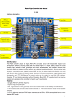
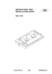
Rabbit Flight Controller User Manual
V1.208
All Rabbit Related
Rabbit net store(international):http://www.aliexpress.com/fm-store/611060
Modules & founctions instructions:
All the Rabbit Products includes: Main board and some founction modules:
1.Rabbit Flight Controller( main board) , with it you can enjoy the founction: Autostability , 3D stunt,PTZstability;
2.Additional board module,with barometer & magnetic on it,
with it you can enjoy the founction: CarFree,height lock ,head lock,Autolanding
3.Ultrasonic module: with it you can enjoy the founction: height Lock (<2.5m),Autolanding
4.GPS module: with it you can enjoy the founction: Gohome, PositionHold
5.Power board: with it you can connect Rabbit Flight Controller to ESC & Battery well.
And some other modules such as OSD etc will be developed in future
1
All the Rabbit products are packed to a group acorrding to the founction in net store:
Group 1 : Rabbit Flight Controller & additional board ,
it has founction: Autostability , 3D stunt,PTZstability; Carfree,height lock(>2.5m) ,headLock,Autolanding
See here: http://www.aliexpress.com/fm-store/611060
Group 2 :Rabbit Flight Controller & additional board & Power board
it has founction: Autostability , 3D stunt,PTZstability; Carfree,height lock(>2.5m) ,headlock,Autolanding
and with the Power board ,it can be connected to ESC &battery well
See here:http://www.aliexpress.com/fm-store/611060
Group 3 : Rabbit Flight Controller & additional board & Ultrasonic
it has founction: Autostability , 3D stunt,PTZstability; Carfree,height lock ,headlock,Autolanding
See here:http://www.aliexpress.com/fm-store/611060
Group 4 : Rabbit Flight Controller & additional board & Ultrasonic & Power board
it has founction: Autostability , 3D stunt,PTZstability; Carfree,height lock,headlock,Autolanding and with the Power board ,it
can be connected to ESC &battery well
see here:http://www.aliexpress.com/fm-store/611060
Group 5 : Rabbit Flight Controller & additional board & Ultrasonic & GPS
it has founction:
Autostability , 3D stunt,PTZstability; Carfree,height lock,headlock,Autolanding,Gohome,PositionHold
See here:http://www.aliexpress.com/fm-store/611060
Group 6 : Rabbit Flight Controller with all modules (additional board & Ultrasonic & GPS & Power board )
it has founction:Autostability , 3D stunt,PTZstability; Carfree,height lock ,headlock,Autolanding,Gohome,PositionHold,and with
2
the Power board ,it can be connected to ESC &battery well
See here:http://www.aliexpress.com/fm-store/611060
Rabbit User Manual
Interface description:
GPS(top)
State Light
Ultrasonic(
middle)
Battery
Voltage
3 (bottom)
Axis Gyro
BarometerC
8-CH
LED
Port
Alarm Port
ARM Chip
ompass
Expansion
Board
8-CH
8-CH
Motor/Servo
Receiving
3-Axis
Accelero
meter
USB Port
Brief Decription:
This Flight controller adopts 32 Digits ARM CPU and latest sensor with Independent research and development software,
ensuring stable,safe and reliable flight in a simple setting suface.The board contains high precision tri-axis gyroscope and
tri-axis accelerometer with compact structure and size.With stable and balance function without any aditional
board.Multi-function: can be connect with ultrasonic, barometer,tri-axis magnetic sensor,GPS etc.,thus to realize height
lock,direction lock, and self- lift-and- down function.8 Channel remote input and 8 Channel motor/servo output.Support aerial
photography and PTZ Self-Balance.The output mode can be setted by user.With USB interface, Upgrades PC and adjusts
parameters without Expansion Board.With PC upgrade tools,it can improve program and upgrades online according to
majority user's requirements .
Features:
3
- 32 digits ARM CPU,50 MHZ frequency
- Support 140g mini quadcopter.
- With high precision tri-axis gyroscope and tri-axis accelerometer for self-stability and self-balance.
- 8 CH receiving ports,can set auxiliary switch channels or PTZ control channel except 4 main joystick channels.
- 8-CH 16 digits high precision PWM output channels,can set 50Hz~500Hz analog/didital servo or non- standard ESC singal.
-Supports
mix-control:GIMBAL,BI,TRI,QUADP,QUADX,Y4,Y6,HEX6,HEX6X,OCTOX8,OCTOFLATP,OCTOFLATX,FLYING_WING,FIEX
D WIND mode and so on. Any other module can be added according to user’s requirement.
- With USB interface and PC upgrade tools,convienent for users to set parameter,and download the newest program.
- 8 LED singal to indicate various mode, convinient to set parameters anytime even for a tiny adjustment. Can connect color
LED strip, makes magnificant and unique night flight.
- Supports 4S battery Voltage test, ensure to test each battery.
- Provide alarm port,facilitate users to set low voltage alarm, the alarm sound will be quicker and quicker with the voltage is
lower and lower.
- With ultrasonic port, makes precision height lock within 2 meters (the best effect with flat ground), switch to barometer height
lock out of 2 meters.
- With equipment self-detection function, make sure safty flight . with sound and light signal during the self-detection.
- With high precision tri-axis magnetic sensor,barometer and GPS port etc.,facilitate users to add functions such as automatic
lift and landing and return.(just buy additional board and upgrade the software online)
- With Independent research and development software, can improve or add new functions as users requirement.
- Output mode optinal: Default ESC output 330MHZ. servo signal output 47HZ.
Specifications:
- Alarm Voltage setting: 2.8 V~3.7V
- Gyroscope: +-2000dps,16 digits resolution ratio, response time:1000HZ
- Accelerometer: -8G,14 digits resolution ratio, response time:800Hz
- Input Voltage:4~6V (provided by a ESC,too high voltage will burn the board)
- Board Size:5.5mmX5.5mm
- Weight:20g
- Working Temperature: -40~+85℃
The product is shown as below:
4
Setting Description:
Package including: flight control board x1, the Dupont line x 1,alarm x 1,battery voltage test line x 1, upgrade USB line x 1
Initial settings: please download and decompress the software package
into a folder, then install the USB driver program,
connect the flight control board to a computer with mini USB line, this will automatically power the flight control board, the light
on the board will be on rolling light state, the computer will prompt that there is a new USB equipment, and automatically install
the driver, when the system prompts that the new USB equipment which is available, see which serial port the new USB
equipment CH340 map into on the system management interface port display, the default is ( COM3 ), then you can open the
setting tool sofeware, if there is port error from the system, please according to your computer serial port select
communication port, when you correct it, the parameters of flight control board will be shown on the software interface. If it is
not the default 4 axis X mode, 330Hz output mode, please according to your frame select your multi axis mixed control mode,
then according to your ESC select the output mode. Parameter setting and selection will be saved at the moment, there is no
need to adjust other parameters temporarily. Finally remove the USB equipment from computer and disconnect flight controller
and computer.
Installation guide:
1.Installation: according to your chosen frame mode make your frame stable,mount the flight control board with LED light
toward the front, plastic pillars are recommended for reducing vibration and resisting impact.Try to advoid the copper pillar,as
the 4 metal holes on the flight control board are connected to the power supply cathode,it may cause short circuit easily. If you
want to further reduce the vibration, you can have the 2mm ~ 5mm thick foam double-sided tape, but do not use springs,
rubber bands such elastic objects. For flight control board is a precision electronic device, please pay attention to waterproof
and avoid mechanical collision, and horn, iron such magnetic material shoud be kept away as far as possible from the
magnetic sensor at least more than 5cm when installation,If you add GPS, the antenna should not be covered by metal
objests.
2. Connection: the flight controller requires at least 4 receivers, up to 8 channels, correspondingly connect remote control
receiver and flight controller receiving channel by channel name(function) with a dupont line.The receiving channel from
bottom to top respectively are: ( 1,Aileron 2,Elevator 3,Throttle 4,Direction,the rest is the auxiliary channel), then, please set
remote control into a fixed wing mode, trim lever all turn to zero, adjust each channel ratio to the default 100%, then connect
the control board with computer, open the debugging tool, select the corresponding COM port to flight controller. Its
parameters is all displayed. Then make the remote control on and click the channel data button “Display Data” which on the
5
right bottom of tool software, each channel data is all displayed, shown as following:
3. Remote Control Initial Setting: operate each channel joystick, observe whether the receiver channel position is right, if not
please change flight controller lines, the effective range data should between 1000 ~ 2000, the middle is about 1500.Different
brands of remote control will be a little different. Then see if the channel direction is accurate, the requirement RC controller
joystick direction is: throttle and elevator is down-small (1000)/up-great (2000), the aileron and direction is left-small (1000)/
and right-great (2000). If the joystick direction is wrong, please have the remote control reverse setting. Finally, operate the
throttle joystick to the end and the channel minimum value must be less than 1100, preferably between 1020 ~ 1090,if not,you
should adjust the throttle trim lever or rudder trim lever on remote control panel to meet this requirement. Regardless of
corresponding channel of remote control is on left or right or other position, the joystick instruction is only related to the
channel name. Output channel supports up to 8 axis, if the motor is 6 axis or less, the rest of two channels will automatically
become PTZ pitch and roll to increase servo stability to control channels.You can set reverse and ratio by the tools.
4. Throttle Range Calibration: Connect your motor and ESC to flight control board by the corresponding channel, from
bottom to top is channel 1 ~ 8, do not install the propeller at this time. Connect the two pins ( TXD, RXD ) with a dupont line
like the diagram, then power it, the flight controller will automatically get into throttle range calibration, the indicator light will
flash quickly at first for 4 seconds, the ESC adjust by itself with music, after that sounds “Beep,Beep~” to confirm throttle
maximum value (1900), and then the flight control indicator light slowly flash for 2 seconds, then the ESC sounds
“Beep,Beep,Beep”,at last once “Beep~” to comfirm the throttle minimum value (1100). Finally flight controller is in initialize
self-detection state, the indicator light is in a rolling state. This can
refer to ESC user manual to see if the automatic throttle
calibration is successful, if the ESC is special thus it can not be
automatic calibration, you should do it by manual operation.
Before the manual operation you must set the remote control
throttle minimum range between 1020~1090. The calibration
method please refer to the ESC user manual.The ESC which you
have calibrated before should calibrate the throttle range again
according to Rabbit’s requirements.Or it will have some bad
phenomenons such as vibration,motor stop etc.
Connect the two pins (TXD, RXD)
with
dupont
line,power
on,
automatically
get
into
throttle
calibration
6
5.Connect the ultrasonic,alarm,expansion board
and GPS, please according to flight control board
backside screen printing. The screen printing is
shown as below,pay attention to the
corresponding pins of the screen printing.
Both side pins on the flight control board are shown in detail
as below:
Middle row to ultrasonic
wave (+5V,TRIG,ECHO,
GND)
Top row to GPS
(+5V,TX,RX,GND)
CH7~CH0 8-CH input
channelscinp +5V
GND
Battery balance (B4,B3,B2,B1,GND)
The last 2-CH M6、M7
to PTZ servo
M0~M7 8-CH output
To LED0/1/2/3/4/5/6/7
ESC +5V input
GND
GND
To wireless alarm
LED+5Voutput
7
6.Warning! To reconfirm the connection without error! Please ensure careful confirmation,for the wrong connection may burn
down your ESC or flight control board! Especially the battery detecting line cannot be connected to other pins.The red line
connect to the athod,green line connect to the cathod (ground), if it is a 3S battery, balance head should be aligned with the
cathode. It has more than 12V high voltage!Ultrasonic wire athod and cathod can not be reversed; Make sure the voltage is
normal before power on; the receiver can not connect to ignition, servo or other large current load! The output power capacity
of flight control board is only 200mA.Note:Only to provide paid repairment service for man-made damage!!!
Battery detecting line to flight control board connection is shown as below:
Protection casing
Blue is negative(ground)
Battery detecting line to the bottom
row,red line is possitive
Battery detecting line to the battery balance head is shown as below:
Battery balance head
Red line is possitive
Red line is possitive
Blue line is negative
Battery balance head
Black line is negative
Battery negative plug to negative notch
If only 3S battery,there is no this line
8
Ultrasonic sensor is fixed below the frame with plastic cable tie and faces the ground,
pay attention to the cathod and cathod color, shown as below:
LED light strip extension board connection diagram is as following
(voltage expansion board’s anode and cathod are connected with battery’s):
9
7.The power self-detection: Put the aircraft on a horizontal place without vibration, power it, do not connect the battery
detecting line at the moment, the ESC will be on its initialization, flight controller sounds “Beep~” once,the indicator light will
be on a rolling flash which means it is on self-detection, then connect the battery voltage detecting plug to battery charging
balance head.The 8 lights on flight control board from left to right on behalf of (1,battery 2,remote control, 3,gyroscope,
4,accelerometer, 5 magnetic sensors 6,barometer 7,ultrasonic 8,GPS ) 8 equipments. The corresponding light will light if the
initialization is successful, not light if it is undetectable or not selected.You can turn on the remote controller first or after power
the aircraft, to avoid the receiver out of control,the setting befor is regarded as a normal signal self-detection, you must
operate any a joystick in self-detection. When the flight controller receive the remote control signal it will sounds " beep"
once, then make the throttle to the minimum position, other joysticks wait still, during detection process the indicator light will
roll once and then stop for 2 seconds to display the self-detection state,when all equipments pass the self-detection, flight
controller will give a long sound "Beep - --", then be into a dormant state (lock).
Batter
y
Remote
control
Gyro
Acceleromete Magnetic
r
sensor
Barometer ultrasonic
GPS
Rolling light runs for 2 seconds then stops for 2 seconds, light bright which
means the self-detection is ok.
8.Operation under dormant state(lock): in dormant state,the indicator light would be bright-dark-bright,change always like
this,just like the breathing effect,that means the aircraft is in a dormant state,at this time it can not fly even if you operate all
the joysticks,very safe.Operate the joysticks in dormant state for a few times which can set the corresponding parameter. Or
enter the sensor calibration, this has detail description below. In a dormant state the throttle is on the minimum position while
aileron should operate to left the minimum position for more than 3 seconds, then enter the active state(unlock). Can receive
the take-off instruction anytime.
Unlock remote control instruction diagram: throttle to minimum, aileron to left, the other channel keeps still, lasts for
more than 3 seconds and unlock
Japanese
mode
American
Mode
Chinese
Mode
10
9.Remote control switch settings: remote controller can connect to at least 4 channels, up to 8 channels.
Channels in sequence: 1,Aileron 2,Elevator 3, Throttle 4,Direction 5, Flight mode switch ( Low - Primary ( Self stabilization );
High - Developing(Non self stabilization ); Middle-Advanced (3D) ), 6,Height Lock Switch ( Low - closed; Middle – Height Lock;
High – High Lock wigh CF open; if you choose the ultrasonic and barometer ,they will connect perfectly in 2 meters ), if the
channel is in different order, then just change the connection line order. The channel data and direction can be seen in the
computer parameter adjustment tool,operating to left should be small and oprating to right should be great fot the aileron and
direction joystick.The Throttle minimum value must be less than flight controller recomended ( 1020~1090),if too great it can't
lock and unlock.You can adjust the throttle trim lever or rudder trim lever on the panel to meet the requirement.For the other
channel setting, the maximum is not less than 1800, the minimum is not more than 1200.It also can be setted as you like,but
too small channel range may lead to that cannot identify some remote instruction such as unlocking,calibration etc.
10.Operation under active state(unlock):in a state of action, if the throttle is the lowest, operating the direction joystick can
change the indicator light mode and color,there are 28 kinds of combination in total for choosing, operate the elevator joystick
can change the rhythm of blinking patterns. If you want to end the flight or it needs to replace the battery, operate the aileron
joystick to right for more than 3 seconds, then the flight controller would enter into the dormant state.
Unlock remote control instruction diagram: throttle to minimum, aileron to right, the other channel keeps still, lasts
for more than 3 seconds and lock
Japanese
mode
American
Mode
Chinese
Mode
11.Check the motor positive and negative: if the motor positive and negative is different from the program, then exchange
any two motor plugs of the corresponding ESC, if the direction is right,you can install the propellers and debug.
12.Propeller installation debugging: please according to the corresponding flight mode, install the posstive and negative
propeller as the motor installation diagram on the user manual, the face which has words should be upward,push the throttle
11
slightly to rotate the motor and see whether each propeller has lift force,if not,recheck it and grab the aircrafe (must grab tightly,
and be careful!),push slightly the throttle, slowly shake the aircraft to see whether the aircraft is the block of your shaking, if
not,but help you to shake,that means the installation may be wrong, please recheck according to the attached diagram. If you
feel the resistance still exists, you can slightly operate each rudder ,to see if the controller is reverse, if the direction is reverse,
you should set the channel reverse switch. Please observe if the motor and properller have eccentric vibration during refueling
process, great vibration would influent the stable flight, please perfect the dynamic balance of the properller before the
following steps.Each debugging parameter can be constantly adjusted and perfected during the flight test, which can make the
aircraft fit for yourself! Finally, you can begin flight.
13. The parameter adjustment: in the dormant (lock) state, throttle to the highest,operate the aileron to the lowest(left end)
for more than 3 seconds into the parameter adjustment setting state, at this time 8 indicator lights represent 8 parameters
( 1,Stability 2,Auxiliary Stability 3, Dynamin Stability 4,Balance 5,Auxiliary Balance 6,Battery Alarm Voltage Trim 7,Aileron
Balance Trim 8, Elevator Direction Balance Trim), the flashing lamp represents the adjusting parameter, the number of other
lights represents the specific setup value, 8 lamps in total, represent the value of 0 to 8, the default value is 4, the
corresponding parameters of light 1, 2, 3, 4, 5 is added with PC debugging tool value; the corresponding value of light 6, 7, 8
+-4 on the base of the PC debugging tool( like the light 6: default lamp position is 4, if the alarm voltage is 3.5V setted in
the parameter debugging software, minus one light towards the left is three lamps always on, that means the alarm voltage
minus 0.1V, is 3.4V; and plugs one lamp towards the right is 5 lamps always on, that means the alarm voltage plugs 0.1V, is
3.6V).You can choose the light you’d like to regulate by the lifting joystick, regulate the specific value with the direction
joystick.After completing the adjustment, throttle to the highest,operate the aileron to the maximum position for more than 3
seconds, save the parameters and exit setup state, return to the dormant state.
Parameter setting instruction diagram: Lock state, throttle to maxmum, aileron to left, the other channel keeps still,
lasts for more than 3 seconds
Japanese
Mode
American
Mode
Chinese
Mode
12
The number of lights on
represents the parameter data
(4)
Which number light
represents which
(3)parameter
Regulation:Choose the light regulated by the lifting joystick,regulate the specific value by direction joystick
Japanese
Mode
American
Mode
Chinese
Mode
Exit the parameter setting instruction diagram: Lock state, throttle to maxmum, aileron to right, the other channel
keeps still, lasts for more than 3 seconds
Japanese
Mode
American
Mode
Chinese
Mode
14.Calibration:let the flight controller enter a dormant state(lock) first.
Horizontal Calibration,put the aircraft on a horizontal place as far as possible, throttle to the lowest and rock the lifting
joystick up,direction joystick to the right for more than 3 seconds and it sounds once“Beep-”and then into the horizontal
calibration,at this time ensure the aircraft on a horizontal state,
the light are running during the calibration, after the end of
calibration, it would automatically return to the dormant state.Note: Horizontal calibration is done when you feel the previous
calibration is not ideal,or there is no need to frequently calibrate.
13
Compass Calibration, avoid strong magnetic field or great iron magnetic material within 5 meters, the open air is the
best!When the throttle is the lowest,rock the lifting joystick up, direction joystick to the left for more than 3 seconds and it
sounds once“Beep-”and then into the geomagnetic sensor calibration,will beep sound into a state of geomagnetic sensor
calibration, at this time please rotate the flight controller slowly and uniformly 2 rounds respectively around 3 axis. Shown as
following: be sure to be slow and uniform, the better calibration, the better flight you have, a total of 60 seconds, the light are
running during the calibration,after the end of calibration, it would also sound once “Beep-” and automatically return to the
dormant state.If you feel that the direction effect is not so good when it change the environment you can recalibrate.
Horizontal calibration joystick rock diagram:
American
Mode
Japanese
Mode
Chinese
Mode
Compass calibration joystick rock diagram:
Japanese
Mode
American
Mode
Chinese
Mode
Rotate slowly and uniformly
2 rounds in horizontal state
M
3
M
2
M
1
M
0
14
2.Rotate
slowly
and
uniformly 2 rounds during
20 seconds with the head
up
M3
M2
3.Rotate slowly and uniformly
2 rounds during 20 seconds
with the side up
M1
M0
M
2
M
3
M
0
M
1
15. Happy flying: after the self adjustment above, you can enjoy your flight! There are 3 flight modes,you can switch it by 3
section switch of channel 5.
1, The primary mode: (minimum position of 3 section switch ) with self stablity function, operate the rudder slightly to correct
and it can fly well, this mode has the best effect in windless environment.
2, The normal mode: (maxmum position of 3 section switch ) is also called the developing mode, the aircraft somehow has a
stable performance, operating the rudder and the aircraft will change the current posture and try to maintain.This mode has
certain resistance to unexpected external force, like the wind etc. The flight posture needs pilot to correct constantly, relatively
quick reaction to operate the rudder, but it cannot work for the intense action. This mode is suitable for most people from entry
to the less violence of flight.
3, The motion mode: (middle position of 3 section switch ) also called stunt mode and 3D mode, the aircraft has high flexibility,
quick reaction to operate the rudder.It is very sensitive to rudder during the flight process, needs pilots’ quick judge and control
ability. This mode can make people as the acme of perfection high difficulty movement. This mode can do some amazing and
astonishing stunt.It is also the very mode to be crash.
Height Lock and CF switch: when you installed ultrasonic or pressure sensor and magnetic sensor,it can achieve height lock
and CF mode flight by channel 6 switch.When turn on the height lock,adjust slowly the throttle to the requirement height,stop
and the height lock process will automaticly be instead of the throttle and then lock the height.If you want to change the height,
as long as adjust the throttle and it will unlock temporarily,until the throttle stops it will automatically enter the height lock again.
Ultrasonic height lock need the flat terrain below without messy objects or protrusion.It needs barometer above 2 meters,and
15
barometer is affected from weather, temperature, pressure etc.The barometer can be covered with thick foam double-sided
tape to eliminate the effects of wind.
Ensure to calibrate the magnetic sensor before you turn on the CF function, rough calibration will affect the effect of
flying.After magnetic sensor calibration, it need to verify the effect.Put the aircraft on the ground, turn on CF function, unlock
and slowly refuel and rock lifting and aileron, observe if the aircraft reactive direction away the ground is the same with the
unlock state,at least test 4 directions, it had better check the 45 degree direction. if you ensure all the direction is accurate,you
can have the flight test now. Note: CF mode flight angle error will increase under high speed rotating,when there are great
lifting and aileron motion, angle error will also increase! Therefore, great rudder flight or 3D mode is not recommended to turn
on the CF function.
If you want to get the aircraft to stay on a specified location (range ) in the air, you need to open GPS switch to help the
location lock, if you want the FPV automatic return function you must also install the GPS option.
16.PTZ connection and adjustment: if the motor channel is less than or equal to 6, then the channel 7 and channel 8 would
be automatically converted to 2 axis PTZ stability output,the channel 7 ( M6 ) connect to pitch servo, the channel 8 ( M7 )
connect to the rolling servo, the compensation ratio and direction can be adjusted through the parameter adjustment tool, the
value represent the ratio, +-represent the positive and negative of direction.
Remote control switch selection suggestions: channel 5 and channel 6 recommend using two three sections switch, if the
channel 5-6 is vacant, flight controller default this two channels are on low possition: channel 5 mode defaults to the self
stability mode, 6 channel defaults to the closed height lock.
Upgrades and points for attention: in order to add new functions or improve the software according to feedbacks of some
model friends, we will provide software upgrade service, the firmware can be upgraded by computer usding the debugging
tools we provided. Every time the software version is upgraded,all the original parameters will be refreshed to default values,
you should have the horizontal calibration and compass calibration again, check and modify the parameters so that it can be
used normally!
The function explain about switch custom
In the custom area of pctools for Rabbit, all the switch can be defined for several function by customerself, there are
three channels(5,6,7) can be defined to switch according to the function necessity .(two three stage switch, one two stage
switch).
16
Autostability Mode: Playing joysticks of remote-controller unit, the aircraft will change the attitude, and after the joysticks
return it will automatically turns to the horizontal state. You should keep the same direction of joysticks and flying toward of
aircraft.
Normal Mode: Playing joysticks of remote-controller unit, aircraft will change the attitude, and after the joysticks return it will
maintain the existing state. If you want recove it to horizontal state, you must push the joysticks to adjust it. If the switch of
autostability and 3D stunt were not ticked , the aircraft will be set to normal mode.
3D Stunt Mode: This mode is the same with the normal, but the stroke of rudder is relatively large and flexible .You can enjoy
3D stunt in this mode, but it is difficult to control for the beginner.
Height Lock Mode: When aircraft hovering and throttle does not move, then it will automatically turns to height lock state.
Height Lock Mode will be cancelled by moving the joystick of throttle . Height Lock is effective when the aircraft is in 0-2m
height just with the ultrasound modules, and it is effective in any height with barometer.
Head Lock Mode: This mode need additional boards(with magnetic) supports. At the Head Lock Mode, the aircraft will
automatic memory the direction. After flying freely , the aircraft will automatically return to the memoried direction when the
joystick of yaw turns to middle
CareFree Mode: This mode need additional boards(with magnetic) supports. When Rabbit unlocked ,the direction is come to
stay (front,behind,left,right is keeping),whenever the aircraft rotated and tilted or pitched,the direction will not change. (pay a
attention : The direction of CF is not same with the Head Lock Mode )
PTZ Autostability: If the motor channel is less than or equal to 6, the 7-channel and 8-channel can automatically be
converted to two-axis PTZ autostability output, 7-channel is conected to the pitching servo, 8-channel is connected to the
rolling servo, the scale and direction can be adjusted by pctools for Rabbit, the value represent the size of the
scale and “+”,
“-” represent direction.
PositionHold Mode:This mode need GPS module supports.The aircraft will automatically hovering near to the coordinate
position where the GPS module acquired when released the joystick of throttle at any time any where in flying.
Gohome Mode: This mode need GPS module supports. unlocking aircraft,the Rabbit records the GPS coordinates where the
aircraft take off from, when the switch of Gohome is turned on, aircraft will automatic come back to the GPS coordinates where
the aircraft take off from and hovering above it.
Autolanding Mode: This mode need ultrasonic module and need Height Lock Mode, you can turn on autolanding at any time
any where when the switch of gohome is off.and when gohome and autolanding are effective at the same time, the aircraft will
back to the home point automatically and hovering above it for 20 seconds,then it will land automatically.
The notes for the Upgrades : In order to add new functions or improve the fireware according to feedbacks of some RC
17
lovers, we will provide fireware upgrading service, the firmware can be upgraded by pctools for Rabbit. all the default values of
parameters will be refreshed when the fireware was upgraded every time. you should do the horizontal calibration and
compass calibration again, check and modify the parameters so that it can be used to fly normally!
14 Multi-mode Installation Diagram
1. Designed to aerial PTZ control(GIMBAL)
Pitching Servo
M/S1
t
rolling servo M/S2
2、Two-axis mode(BI)
M1
M3
M4
M2
3、Three-axis mode(TRI / Y3)
M2
M3
M4
M1
18
4、Four-axis + mode(QUAD + / 4+)
M4
M2
M3
M1
5、Four-axis X mode(QUAD X / 4X)
M4
M2
M3
M1
6、Four-axis Y mode(Y4)
M2
M4
M3
M1
19
7、Six-axis Y mode(Y6)
M3
M2
M6
M5
M1
M4
8、Six-axis HEX mode(HEX6)
M5
M2
M4
M3
M1
M6
9、Six-axis X mode(HEX6X)
M4
M2
M5
M6
M3
M1
20
10、Eight-axis X mode(OCTO8X)
M4
M2
M8
M6
M3
M1
M7
M5
11、Eight-axis + mode(OCTOFLATP)
M5
M2
M1
M8
M6
M4
M3
M7
12、Eight-axis FLATX mode(OCTOFLATX)
M1
M6
M2
M5
M7
M4
M8
M3
21
13、FLYING_WING mode
S2
M1
S3
14、FIEXD WING mode
M3
M1
M2
M4
22
Rabbit GPS User Manual
Love Flight Team
Product features:
Rabbit GPS adopts ublox brand GPS module which is regarded as the best for the performance.High accuracy, low
drifting, stable and high price ratio.
Installation prerequisite:
First of all, this Rabbit GPS needs a very stable and reliable aircraft debugged.The throttle has not obvious vibration all
range in the self stable mode. Rack, motors, propellers and all the connecting plug cables should be firmly fixed to prevent
loss and poor contact.And you should know fairly well the battery flight time.
Secondly,flight controller must be installed with function expansion board and the magnetic sensor and pressure
gauge must be working! There are lots of test methods, the adjustable tool can be the first, connect the flight controller to the
computer with USB cable, open the adjustable tool, click the display data, rotate the FC horizontally, observe if the magnetic
angle changes is the same? Mainly see the flight controller relative angle is how much when the magnetic angle is 0 degree,
90 degree, 180 degree, 270 degree,if it is close to 90 degree, and if the error is too large,it needs recalibrate.You can also
open CF function to flight and test if the magnetic sensor is normal;observe if the barometric height datas have little and slow
value of change around one point, if it doesnot change or change quickly and the range is greater than 20 decimeters which
means the barometer is not working properly. Also you can flight in the outdoors to test height lock effect. If there is no
problem for the height lock,CF and heading lock test, then the Rabbit GPS can be installed.
Installation:
Fix the rabbit GPS high with nylon pillar, also you can use in other ways, GPS ceramic antenna faces up, GPS and
Rabbit Flight Controller should keep a distance for more than 10cm (please see the picture)
23
Connecting:
The rabbit GPS is connected to the flight controller pinout with 4Pin Dupont line as above diagram: VCC for anode,
GND for cathode, the red line in the figure for +5V, deep blue line connects to the cathode ( GND ), two middle lines are
signal lines, and the anode and cathode must not be reversed. Fix the connecting cables firmly and avoid to be in the loose.
Power on:
Power the flight controller whose marquee light will be on, and the LED on GPS board also lights up, which means
the power is normal.
Usage:
Firstly connect the flight controller to the computer with USB calbe, open the adjustable tool, GPS option is on in the
selection of sensor area. And then press and return, loose rod and point lock,automatic landing are respectively assigned to
your own switching channel. Finally,remember the normal work of Rabbit GPS needs the cooperation of self stability mode,
height lock, magnetic sensor ( CF and heading lock cannot be open), please make these functions have appropriate switch!
Function explanation:
GOhome: when properly connected, choose the GPS function and receive a valid signal,the flight control will remember the
unlocking position. When it takes off from unlocking point,open the press and return switch,the FC can automatically control
the direction of flight and fly back the take-off point. The height can be controlled by throttle yourself during the return, and still
have the loose rod and point lock function.However the throttle is particularly sensitive for the pressure height lock, please
slowly regulate, don't operate throttle lever violently. After return if you choose the automatic landing and when it return to the
take-off point within10 meters, start to land automaticly.
Autolanding: with the height lock function and make it on, when turn on the automatic landing switch it start to land
automaticly from the sky. A barometer supports landing above 2 meters, what supports landing below 2 meters is ultrasound
module. In case of emergency, the throttle can still be used, but push up or down the height,automatic landing will continue. If
you don't play solo automatic landing function, it is suggested that you set the automatic landing and press & return in the
same switch position, so that it begins to land automaticly when the flight controller returns to the unlock and take-off place
( home point ) in the range of 10 meters.
PositionHold: Rabbit GPS works normally and open the loose rod and point lock function, any time when you stop operating
the remote control aileron and elevator,the flight controller will be hovering automaticly in the current position, the horizontal
position and the height position can be adjusted respectively. If you open the press & return function at the same time
which has the priority.
Searching satellite signals outdoors:
24
To be more precise location,the GPS should be used in the open air.If there are buildings or other blocks around,
even it can search satellite signals and get location,it is unstable and the flight controller will move in a wide range. When
the power on in the outdoors, the FC will have marquee lights and come into self check, other self check you can have
reference in FC user manual. GPS can be instructed by the eighth LED light, generally the searching time is within 1 minute,
If it is not so long time to the last power time, the satellite signals searching can be faster! When the flight controller have
checked that GPS received 6 satellites and got location, it will have a sound of "Beep-", and the GPS self-checking pass.If
other equipments self-checking is completed,the FC will be in the state of breathing lights.At this time, operate the rudder to
the left, you can switch LED display modes, switch the display between breathing lights and satellite numbers. The satellite
number searched is bright light number plus 5, it shows 13 satellites at most.Generally there is less GPS satellites number
when it just power on,and the location is also not so accurate, flight controller will move in a wide range, but these will be
greatly improved waiting for a while.
Take off and return:
When the flight controller self-checking pass, it can take off. Before fly far away at the first time, you must have several
tests in close distance to be familiar with the GPS functions, also check the stability and reliability of all the equipment and how
far the capacity of battery can be for. It is suggested that it donot fly far with big wind, the flight cotroller return speed will be
slow, maybe the return time will be beyond your battery time. In the wind the return speed can be accelerated, the FC return
to the take-off point and fly too much, do not be in panic, it will automatically
correct and back to the take-off point, or you can manually assist to correct the position, but do not operate the throttle in a
panic. In order to avoid this situation, it is advised that the player stands back 5 to 10 meters to the take-off point.
Special notes:
The normal work of GPS module has a great relationship with GPS signal, any weather changes are likely to affect the
GPS signal intensity, thus influent the normal work of the GPS module,especially during the flight. Due to climate change,
building block, the difference of terrain,it is likely to lose the satellite signals and affectthe normal work of the GPS module.
In addition, in the narrow buildings even though with stronger signal, it can receive enough satellites to unlock,however,
most of the satellite signal is reflected signal, the location accuracy is poor, also can cause the flight controller drift around and
move in a wide range. Therefore, you players should consider all kinds of factors on GPS signal influence and keep safety
first, effectively prevent all sorts of accidents.
We do not bear any responsibility for various accidents or loss of property during the flight process.In addition, it had
better avoid violence flight with the GPS module, especially violent landing or crashing. As the dramatic impact may cause
damage to GPS module.
25
Q&A: About Installation Of Rabbit Flight Controller
Love Flight Team
1.Q: Is the wire splice of Rabbit flight controller different from aother flight control?
A: No , it’s wire splice must be in accordance with the requirements of the specification
2.Q:How to fix it’s head section ?
A: A Row of LED lights on the Rabbit Flight Control stand for the head direction.
3.Q: Which paddle should be equipped with Clockwise motor paddle ?
A:To be equipped with anti-paddle which is marked with “R”, for example 10*45R. In fact, to fix paddle is very easy, and
you just put the word side up and turn the motor according to the instructions, after the motor started up, it downruned, and it
is installed on
4.Q: Why the connections are right , but the aircraft can not unlock?
A: There are several reasons: 1. the minimum of Throttle is less than 1100, you adjust the stroke of the throttle to large,in
order to set the throttle minimum is between 1020-1080 best. 2. Marked the non-existing sensors in the configuration software
such as you marked the ultrasonic, but ultrasonic is not connected.
5. Q:After Aircraft installed, what steps should calibrate or set first before unlock the Rabbit Flight
Controller to take-off?
A: According to the wiring diagram on the instructions,,although the Aircraft has been installed ok, the aircraft can not
take off, there are several things must be done as follows before enjoying it: 1, Set the throttle stroke
2.Do horizontal
calibration 3. calibrate the Magnetic (if additonal boards hasnot been installed, this step may be omitted). After these steps
done, you can unlock the Rabbit and start to take off .
6. Q:How to check whether the channel of the remote controller is reverse or not?
A:There are two ways to check:
First, plug Rabbit into USB and run the pctools of Rabbit ,click the button “display data” , observe the data in receiving
channel data box.For channel of the direct or aileron, if we push the joystick to the left,the data turns smaller, and if we push
the joystick to the right, the data turns larger; For the channel of the throttle or elevator, if we push the joystick to the
front ,the data turns bigger.
Second, unlock the aircraft first, push the throttle to start the aircraft, then hold the aircraft in hands, play each joystick,
and see whether the response of the aircraft is in accordance with the direction of the joystick.If inconsistent, then change the
corresponding channel to the reverse.
26
7. Q: I did not connect the ultrasonic ,but why not pass self-test?
A: If you have ticked ultrasonic or other sensors just in the pctools of Rabbit, but not connected to corresponding sensor,
the system can not pass self-test. This is designed for security. When the Rabbit checked no sensor ,it is considered abnormal,
so it can not pass self-test. If you want to test height lock with barometer , you can unplug the connection of the ultrasonic after
self-test is finished,
8. Q: Why are the speeds of four motors different after I do horizontal calibration ? and it almost
overturn after taking off?
A: The correct operation of the horizontal calibration is: throttle joystick to minimum + yaw joystick to the right + joystick of
elevator to the largest, and hold the state for more than 3 seconds, until the Rabbit sounds "Bee--", then it is really do
horizontal calibration, calibration takes 3-5 seconds, when the calibration is finished, the Rabbit will sound "bee--" and the LED
will turn to the breathing state. In this step, Rabbit will sound a “Bee-“ if you push the joystick of yaw or elevator when the
throttle is lowest ,and this sound indicate the Rabbit will adjust blinking mode of the LED, not indicate it is doing horizontal
calibration
9. Q: Is the voltage of the Rabbit Flight Controllor measured accurate?
A:The accuracy of the voltage that the Rabbit Flight Controllor measured is very high, it was calibrated with four and a half
volmeter, it’s accuracy is more higher than voltage displayer. and it is also too much higher than normal volmeter. If you think it
is not accurate, you can calibrate it in the software.
10. Q:How long can it fly when we heard the alarm of the Rabbit?
A:This is more related to the quality of the battery, if the internal resistance of battery is small, the voltage drop cost in
battery are small; if the internal resistance of battery is big, the voltage drop cost by battery are big.the alarm of the Rabbit is
also divided into "Didi" ,fast ring , and bell, This is to remind the voltage of the size to alarm voltage. Specifically you can
measure the battery voltage after hearing the first few times alarm sound, then you can grasp the performance of your
batteries. Some battery can fly after the sounding of the alarm.
11. Q: The firmware I used now is flying very stable, if the new firmware is
published, should I upgrade it?
A: Upgrade is needed. RC lovers who enjoy a Cool flying with old firmware can be better to fly after the new firmware
upgrade, generally the new firmware offers performance improvements or modify some BUGS of the old firmware, it is need to
upgrade.
27
12.Q: The previous parameters whether can be used or not after upgrade the new firmware?
A: Generally ,the previous parameters can not be used any more, when the new firmware is published, there will be
provided with the default parameters for reference, the default parameters for a variety of different frame can be used to fly. Of
course, the size, motor, paddle, and weight of each frame is not the same, you can fine-tuning it on the base of default
parameters to achieve the perfect state.
13. Q: How to check the sensors such as ultrasonic etc whether work correctly or not?
A: The pctools for Rabbit can observe the data of the magnetic, ultrasonic, and barometer. Firstly, calibrate the magnetic,
then plug Rabbit into the USB, and make the frame rotate 90 degrees, observe the angle value displayed in magnetic
box,whether it is also turn 90 degrees , if not, it is the magnetic calibration did not do well, you need to calibration again; move
the frame up and down ,whether the data of the ultrasonic and the barometer changes, the changes of the ultrasonic data
should not mutation.
14. Q: Why is magnitude of voltage in the pctools for Rabbit more times than real voltage values?
A: The Voltage displayed in pctools does not show decimal point. For example, the voltage displayed in pctools is 415.
That is to say, the real voltage of battery is 4.15V. If you need to calibrate the voltage of battery, decimal point is not written.
15. Q: Why spining quickly in the first flight after the aircraft installed ok
A: You must check it carefully whether the ESC connected ok or not, whether the positive or reverse of paddle is
installed ok or not ,according to the specifications.
16. Q: Why does the data of barometer fluctuate greatly up and down?
A: Because barometer is affected by wind and airflow, you must add sponge in the barometer. Density of sponge is not too
little, and the small holes on barometer can’t be stemed by glue or gummed paper . the sponge fixed in barometer can
decrease disturbing by airflow. The precision of barometer is greatly increased.
17.Q: Why parameter doesn’t show after the Rabbit pluged into USB?
A: After the Rabbit pluged int to USB, you must do as following steps:
1.Run pctools for Rabbit.
2.Select the COM port correctly in the interface of the pctools of Rabbit. (the default COM port is COM3,you must
change it according to your computer.) if you do that , all kinds of parameters(included the Version NO.) will be
shown on the interface.
3.if you click the button “display data” ,then all data in receive or output box can be shown on the interface of the
pctools for Rabbit.
28
18.Q: When the parameter is setted in Rabbit, can we need to save it?
A: After parameters were setted or Sensors were ticked in pctools for Rabbit, it directly write into the Rabbit Flight
Controller and don’t need to save additionally. If you need to verify whether is written successfully, you can select the COM
Port again and all data will be refreshed .
19.Q: why the aircraft is always up and down after it’s height more than two meters and the aircraft
turns into height lock by the barometer?
A: The data of ultrasonic and barometer are normal on the tools, but height lock is not ok, this is because of the height is
increasing ,and ultrasonic echo will become weak, external signal will disturb the receiveing, the data outputed by ultrasonic
will be not correctly. Therefore, we must decrease effect by high-frequency vibration as much as possible,and we must adopt
damping measures to buffer the ultrasonic.
20.Q: Whether the speed of GPS gohome can be setted by ourself or not?
A: The speed of GPS gohome is controlled by Rabbit Flight Controller automatic, and it will not be opened to RC lovers
recently.
The Manual Of The Pctools For Rabbit Flight Controller
Love Flight Team 2012-2-28
一、Instructions:
This pctools is used to write or read data from the Rabbit Flight Controller and it will be updated according to the
necessity of the Rabbit Flight Controller.
二、Installation
1. Extracting pctools package:
Extract the package into the same folder (you must ensure the same folder)
2. Install usb driver:
If your operating system is the 32-bit systems (including win7), then run USB(32bit)Driver.exe;
If your operating system is the 64-bit systems (including win7), then run USB(64bit)Driver.exe
3.Register the OCX:
If your computer operating system is the 32-bit systems (including win7), then run setup(32bit).bat;
29
If your computer operating system is the 64-bit systems (including win7), then run setup(64bit).bat.
4.Run pctools for Rabbit Flight Controller:
Double click the " Love Flight Tools For Rabbit Flight Controller V1.209(English).exe”.
(Note: pay close attention to the computer prompts, if it is necessary, please select " Allow running " option, ensuring the
pctools starts normally, and to prevent anti-virus software prohibiting the pctools as a virus .)
5.Close and minimize
Click the button "╳" on upper right corner of the interface to turn off the pctools, you will be prompted to confirm the
operation before the closure.
Click the "_" button can minimize the pctools.
三、Instructions for the interface and usage
1.Click each button on the interface, the prompt of corresponding function usage and explain will be shown.(except for button
“select upgrade file”. “upgrade", "display data “)
2.Each re_select the the COM port,Pctools will read the data from the Rabbit Flight Controller,and the data displayed on
interface will be refreshed
3. The pctools’s interface as shown below:
30
4. Function and Usage instructions
I) COM port operation:
The first time you run the pctools on the same computer, the COM3 will be opened by default, if the COM port failed to open,
please click the “OK” on the prompted interface to open the software first ,then select the COM port you want to use in serial
port list box on the interface of pctools according to your computer , until the COM port you selected is successfully opened
and normally used .
The COM port which are opened will be saved as the default COM port to use next time.
II) Firmware upgrade:
First click button "sele_update_file" ,and select the appropriate upgrade file in the dialog box, (if the file is the wrong choice
will be given prompt, you need to re-select), and then click "upgrade" button at the right to start the firmware upgrade, and it
will display the firmware upgrade process. (please do not interrupt the upgrade during the upgrade process, otherwise, the
original firmware and new firmware of the Rabbit Flight Controller will be damaged.)
III) Board parameters setting
According to the need of your flight, drag the slider on the slider bar to a appropriate location of the data respectively (the
specific values will be shown in the display box on the right of the slider), release the mouse, the value will immediately be
wrote and saved in the Rabbit Flight Controller’s board (no need to click the button on the left side of the slider). Click the
button on the left side of the slider ,it will display the corresponding prompt.
Special Note: when you set the alarm voltage, the data value of the slider’s location on the slider bar is 100 times the
real voltage value what you want set in.For example, if you set the alarm data 350 into the box, it means that the real alarm
voltage is 3.5 volts.
IV) The switch of custom
Please ticked the item according to the function necessity and your remote-control unit
①each row is one function: you can select according to the channel of your remote control and switch position.For
example: If you only want to set low-bit switch of 5-channel as autostability function, then you just ticked box on the first row
and first column , At this time, only low-bit switch of 5 channel turn on , it is provided with autostability function, if you do not
use this low-bit,it does not have autostability function.
You can also check high, medium and low grade of 5,6-channel at the same time, In this way, use anyone of the six stalls
have autostability function
If no ticked on this row, it means that no matter which switch position of which channel ,it do not have the custom funtions.
②Due to the function needs: " autostability " and "3D stunt", " Head lock"and" CareFree "can not be defined in the same
31
switch position of the same channel, so that the same column can not be selected at the same time. For example, you can not
define the low switch position of 5-channel as “Self-stability” and “3D special effects” functions at the same time. Nor can it be
defined as “Heading lock “and “Undirected CF” functions as the same. But you can define the low-grade switch position as
“Self-stability “ and define medium -grade switch position as "3D special effects".
③Due to the function needs: “autolanding”must be combined with the "height lock", Therefore, when you select the
function "autolanding”, the pctools will automatically ticked "height lock" function. Accordingly, when you cancel the "height
lock" function, the “autolanding “ function will be canceled at the same automatically.
V) Sensor usage:
All of the various functional modules connected with Rabbit flight control board need to be selected here. Only the sensor
item was ticked,the Rabbit Flight Control has a corresponding function, otherwise it will have no corresponding function.
VI) Battery voltage display and calibration
Battery voltage display:
Ensure the battery has connected with the Rabbit Flight Control normally, and then start the pctools for Rabbit, Each chip
voltage of the battery pack will be
shown in four display boxes.
If it was connected to the battery after starting the pctools, you need to re-select the COM port to refresh the data, then
each chip voltage of the battery pack will be displayed in the corresponding display boxes.
Battery voltage calibration:
Please measure the battery voltage accurately with the voltmeter first ,and then input the value to the appropriate
displayed box (Note: if the voltage you measured is 4.12V,you should input the data 412 into the corresponding box, you
must ensure the consistency of the data format), and then click "calibration" button on the right side. The battery voltage will
be calibrated at once.
VII)Data display area(Data of each channel, magnetic angle, height of ultrasonic,Height of barometer)
Click the button "Display data", each data will be displayed and updated continuously. At the same time, the other
functions of this tools will be turned off. Click the button "stop display" ,the data display function will be stopped at once ,the
other function will be recovered again.
during the state of displaying data, the check box below the data box is available, ticked the check box to enable the
corresponding channel to reverse.
VIII) Data save and recovery
Data save
Click the button “Save current data” in the Parameter setting area, all parameters can be saved to a file, you can easily
32
select the path and floder to save the file,and you can change the file name default (default file name : LFMC_Data.txt ), which
can be convenient for RC lovers save the aircraft data so that to study and DIY.
Load data
If you want to load the default parameter values of Rabbit Flight Control, please select the appropriate type of frame in
the upper right list box, then the corresponding default parameter values will be restored to the Rabbit and pctools interface is
displayed automatically (no need to click the button “load Data” in the list box on the left). If click the button "Load Data " , the
prompt about this function will be displayed.
You can also select the “load from the file saved by yourself” item to load the data from the file you saved.
Note: Do not change the format of file you saved, especially do not change the format of the data, any changes will lead to
error)
Thank you for your enjoying the Rabbit !
33