1
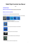
FrontLoad Bill Validator Series - Operation and Service Manual CashCode FrontLoad Series FrontLoad Bill Validator Operation and Service Manual Part 1. Operation Manual Rev. 09-2002 Part 1. Operation Manual PAGE 1-1 FrontLoad Bill Validator Series - Operation and Service Manual Table of Contents INTRODUCTION .............................................................................................................. 1-3 PRODUCT OVERVIEW ................................................................................................... 1-4 GENERAL SPECIFICATIONS ........................................................................................ 1-7 DIMENSIONS ................................................................................................................... 1-8 GENERAL WIRING DIAGRAM ..................................................................................... 1-14 MODULAR SYSTEM ..................................................................................................... 1-15 CHOOSING PART NUMBERS FOR THE BILL VALIDATOR ....................................... 1-27 INSTALLATION .............................................................................................................. 1-28 INTERFACE CONNECTION .......................................................................................... 1-34 SWITCH SETTING ......................................................................................................... 1-37 MAINTENANCE and SERVICE .................................................................................... 1-40 SOFTWARE UPDATES ................................................................................................. 1-42 TROUBLE-SHOOTING .................................................................................................. 1-46 TECHNICAL SUPPORT ................................................................................................ 1-54 Rev. 09-2002 Part 1. Operation Manual PAGE 1-2 FrontLoad Bill Validator Series - Operation and Service Manual Congratulations! You have selected one of the most innovative cash-handling devices of its kind in the worldCashCodes new generation of FrontLoad bill validators. The FrontLoad bill validator is designed to help you with your high-security cash-handling needswith break-through features CashCode has offered customers for yearsincluding an easy-access clamshell design and a beltless, roller-based money transport system. CashCodes FrontLoad bill validator allows you to easily upgrade sensors and software, install high-capacity cassettes, validate multi-width currencies and rely on the most effective security technology in the industry. This manual is designed to give you an easy overview of installation, use, and device upgrades for CashCodes line of FrontLoad bill validators. Rev. 09-2002 Part 1. Operation Manual PAGE 1-3 INTRODUCTION INTRODUCTION FrontLoad Bill Validator Series - Operation and Service Manual PRODUCT OVERVIEW PRODUCT OVERVIEW CashCodes FrontLoad bill validator was developed to validate a wide variety of paper currencies. The design of the FrontLoad is based on modular principles. The units modular design provides extreme flexibilityallowing you to customize the bill validator to suit your individual requirements. The CashCode FrontLoad bill validator provides front access to a lockable cassette. Rev. 09-2002 Part 1. Operation Manual PAGE 1-4 FrontLoad Bill Validator Series - Operation and Service Manual PRODUCT OVERVIEW The FrontLoad bill validator consists of six main modules. Each module is available in different variations, to suit your needs. The picture below illustrates the different modules, and gives part names. Memory Stick (for software updates) Validating Head Bezel (CashCode Standard Bezel is shown) Housing (600 bill Cassette with Lock Bracket is shown) Power Interface Module Cassette (600 bill Cassette is shown) Rev. 09-2002 Part 1. Operation Manual PAGE 1-5 The transport mechanism can transport bills of different sizes from 62 to 82 mm wide, and from 125 to 172 mm longwhich encompasses most currencies. Some currencies have different widths depending on bill denomination. For accurate validation of such currencies, the Validating Head with a centering mechanism should be used. For currencies with a single width, the Validating Head with a fixed width path can be used. Replaceable Sense-a-Click sensor modules recognize and validate a specific currency depending on the hardware installed in the Sense-a-Click module. The Power Interface module allows the freedom to choose interfacesaccording to the your own personal specifications. The Lockable Cassette is used for temporary storage of validated bills. It can be locked with two standard ¾ tubular locks . The Cassette is available in two sizes: a 600 or 1000 bill variety. Cassette capacity refers to the space inside the Cassette used for bill stacking. Sense-a-Click (upper) Sense-a-Click (lower) The Validating Head carries a set of Sense-a-Click modules And bill capacity (600 or 1000 bills) refers to the amount of new bills that the Cassette can store. Street grade bills require more space and a lower amount of them can be stored. The Housing joins all the other modules. Housing is permanently secured inside a gaming or vending machine. There may be a mechanism for locking the Cassette within the Housing (Lock Bracket), or there may be a Plain Bracket. The Housing also contains security switches, which detect Cassette removal. Several Bezel styles are available for the FrontLoad. Software updates can be easily completed with a Memory Stick. Modular design allows the replacement of failed modules in the fieldin just seconds! Rev. 09-2002 Part 1. Operation Manual PAGE 1-6 PRODUCT OVERVIEW FrontLoad Bill Validator Series - Operation and Service Manual FrontLoad Bill Validator Series - Operation and Service Manual GENERAL SPECIFICATIONS Insertion......................................................................................................Lengthwise in 4 directions Validation rate.............................................................................Not less than 96% on first insertion Width of bill, in mm.........................................................................................................From 62 to 82 Time of identificaion....................................................................................................2.5 (from time of bill insertion to time that credit is issued, in seconds) Full validation time, in seconds: Multi-width FrontLoad .............................................................................................4.5 FrontLoad...............................................................................................................3.5 External interface: a. Opto-Isolated, 12 Volt CC FLBDP b. CCNET c. CC-BDPS d. Isolated Pulse Low Current, 12 Volt CC-IPL e. IGT NetPlex Maximum stacking capacity of new bills in Cassette..........................................600 or 1000 Power supply voltage*..........................................................................12 V.D.C. ± 1.0 V. or 24 V.D.C. ± 4.0 V. Current consumption*: maximum operating current ................................................................................... 2.0 A. maximum standby current....................................................................................... 0.2 A. Power consumption*, W: Idle mode..........................................................................................................2.4 W. Validation mode..................................................................................................12 W. (*= Parameters for validator without active light bezel) Environment: a. Operating Temperature.......................................................................... 0 ºC to +50 ºC b. Storage Temperature............................................................................ -5 ºC to +60 ºC c. Humidity (non-condensing)........................................................................ 30%-90%RH Rev. 09-2002 Part 1. Operation Manual PAGE 1-7 GENERAL SPECIFICATION Maximum length of bill, in mm........................................................................................................172 Minimum length of bill, in mm.........................................................................................................124 Bill escrow............................................................................................................One bill FrontLoad Bill Validator Series - Operation and Service Manual DIMENSIONS BILL VALIDATOR WITH STANDARD BEZEL, 600 BILL CASSETTE AND LOCKING MECHANISM DIMENSIONS & : ( , 9 % : ,( 9 ' : ,( 9 Rev. 09-2002 $ : ,( 9 Part 1. Operation Manual PAGE 1-8 FrontLoad Bill Validator Series - Operation and Service Manual BILL VALIDATOR WITH STANDARD BEZEL, 600 BILL CASSETTE AND NONLOCKING MECHANISM ' : ,( 9 DIMENSIONS & $ & & : ( , 9 Rev. 09-2002 $ : ( , 9 Part 1. Operation Manual PAGE 1-9 FrontLoad Bill Validator Series - Operation and Service Manual BILL VALIDATOR WITH STANDARD BEZEL, 1000 BILL CASSETTE AND LOCKING MECHANISM DIMENSIONS ' : ( , 9 % % : ( , 9 $ & : ,( 9 Rev. 09-2002 ,1 + 6 8 3 Part 1. Operation Manual $ : ,( 9 PAGE 1-10 FrontLoad Bill Validator Series - Operation and Service Manual DIMENSIONS BILL VALIDATOR WITH STANDARD BEZEL, 1000 BILL CASSETTE AND NONLOCKING MECHANISM $ ,1 + 6 8 3 Rev. 09-2002 Part 1. Operation Manual $ : ,( 9 PAGE 1-11 FrontLoad Bill Validator Series - Operation and Service Manual DIMENSIONS BILL VALIDATOR WITHOUT BEZEL, 600 BILL CASSETTE AND LOCKING MECHANISM Rev. 09-2002 Part 1. Operation Manual PAGE 1-12 FrontLoad Bill Validator Series - Operation and Service Manual DIMENSIONS BILL VALIDATOR WITH SMART CARD READER, 600 BILL CASSETTE AND LOCKING MECHANISM % : ,( 9 $ : ,( 9 Rev. 09-2002 Part 1. Operation Manual PAGE 1-13 FrontLoad Bill Validator Series - Operation and Service Manual GENERAL WIRING DIAGRAM GENERAL WIRING DIAGRAM Rev. 09-2002 Part 1. Operation Manual PAGE 1-14 FrontLoad Bill Validator Series - Operation and Service Manual MODULAR SYSTEM A Modular System is an interchangeble group of partseasily cofigurable to a users specifications. Below is a more detailed description of each module and its features. VALIDATING HEAD 2) The Validating Head with a centering mechanism has a self-adjustable bill path. The width of the path is automatically adjusted to accommodate each bill. This type of Validating Head is useful for currency where the width of the bill depends on the denomination. Rev. 09-2002 Part 1. Operation Manual PAGE 1-15 MODULAR SYSTEM The Validating Head has the following options: 1) The Validating Head with a fixed width path is available for bill widths 62, 64, 66, 68, 70, 72, 74, 76, 78, 80 and 82 mm. FrontLoad Bill Validator Series - Operation and Service Manual 3) The Model of Validating Head reflects the type of electronics used inside, and determines the compatibility with other modules. D escription FLV-0110 Bi ll wi dth 62 mm A FLV-0210 Bi ll wi dth 64 mm A FLV-0310 Bi ll wi dth 66 mm A FLV-0410 Bi ll wi dth 68 mm A FLV-0510 Bi ll wi dth 70 mm A FLV-0610 Bi ll wi dth 72 mm A FLV-0710 Bi ll wi dth 74 mm A FLV-0810 Bi ll wi dth 76 mm A FLV-0910 Bi ll wi dth 78 mm A FLV-1010 Bi ll wi dth 80 mm A FLV-1110 A Bi ll wi dth 82 mm Multi -wi dth MFLV-2110 centeri ng mechani sm Rev. 09-2002 Part 1. Operation Manual Model A Av ailability yes yes MODULAR SYSTEM Part number yes PAGE 1-16 FrontLoad Bill Validator Series - Operation and Service Manual Listed below is the appropriate Validating Head part number, which varies according to country. Validating H ead part number A r g e nt i na FLV-0310 A us t r a l i a FLV-0310 A us t r i a B r a zi l FLV-0310 C a na d a FLV-0510 C hi l e FLV-0510 C hi na MFLV-2110 C o lo mb i a FLV-0510 D o m i ni c a n R e p ub l i c FLV-0310 E ur o MFLV-2110 Gre a t B ri ta i n MFLV-2110 H o ng K o ng MFLV-2110 Japan MFLV-2110 K o re a MFLV-2110 M e xi c o FLV-0310 N e w Ze a l a nd P hi l i p p i ne s MFLV-2110 FLV-0310 R us s i a MFLV-2110 S c o t l a nd MFLV-2110 S o ut h A f r i c a U k r a i ne US A FLV-0510 MFLV-2110 FLV-0310 U S A + C a na d a MFLV-2110 U S A + M e xi c o FLV-0310 V e ne zue l a FLV-0510 K a za k hs t a n Rev. 09-2002 MFLV-2110 Part 1. Operation Manual MODULAR SYSTEM C o u n try (c u rre n c y ) MFLV-2110 PAGE 1-17 FrontLoad Bill Validator Series - Operation and Service Manual SENSE-A-CLICK® MODULES Sense-a-Click is a set of two modulesone upper and one lower. In order to be compatible with each other, both modules must have the same part and model number. The Sense-a-Click set offers the following options: - Color and position of the optical sensors; - Number and position of the Inductive sensors; - Capacitive sensors; - Model, which reflects the type of electronics housed inside, and determines the compatibility with other modules. Depending on the bill type, the following Sense-a-Click part numbers are available: Part N umber for Sense-a-C lick Set of two modules U p p er module L o we r module Model Argenti na AR FLS-1704 FLS-1704U FLS-1704L A Australi a AU FLS-1704 FLS-1704U FLS-1704L A Brazi l BR FLS-1704 FLS-1704U FLS-1704L A C anada CA FLS-1801 FLS-1801U FLS-1801L A C hi le CL FLS-1704 FLS-1704U FLS-1704L A C hi na CN FLS-1705 FLS-1705U FLS-1705L A C olombi a CO FLS-1704 FLS-1704U FLS-1704L A D omi ni can Republi c DO FLS-1704 FLS-1704U FLS-1704L A Euro EU FLS-1704 FLS-1704U FLS-1704L A Great Bri tai n GB FLS-1704 FLS-1704U FLS-1704L A Hong Kong HK FLS-1705 FLS-1705U FLS-1705L A Mexi co MX FLS-1705 FLS-1705U FLS-1705L A New Zealand NZ FLS-1704 FLS-1704U FLS-1704L A Phi li ppi nes PH FLS-1704 FLS-1704U FLS-1704L A Russi a RU FLS-1704 FLS-1704U FLS-1704L A South Afri ca ZA FLS-1704 FLS-1704U FLS-1704L A Ukrai ne UA FLS-1704 FLS-1704U FLS-1704L A USA US FLS-1704 FLS-1704U FLS-1704L A USC A FLS-1901 FLS-1901U FLS-1901L A Venezuela VE FLS-1705 FLS-1705U FLS-1705L A Scotland SL FLS-1704 FLS-1704U FLS-1704L A USA + Mexi co USMX FLS-1704 FLS-1704U FLS-1704L A USA+Great Bri tai n USGB FLS-1704 FLS-1704U FLS-1704L A C hi na+Hong Kong C NHK FLS-1705 FLS-1705U FLS-1705L A KZ FLS-1704 FLS-1704U FLS-1704L A USA + C anada Kazakhstan Rev. 09-2002 Part 1. Operation Manual Upper Module MODULAR SYSTEM C urrency Lower Module PAGE 1-18 FrontLoad Bill Validator Series - Operation and Service Manual POWER INTERFACE MODULE MODULAR SYSTEM The Power Interface Module offers the following options: 1) Input power: 12 VDC or 24 VDC; 2) Interface (see chart below for complete list of interfaces) 3) Model: reflects type of electronics inside (A with linear voltage regulation, B with switching voltage regulation). Model B provides higher power and must be used when additional modules are included in the FrontLoad Bill Validator (e.g. Smat Card Reader) 4) Connector for Cassette Touch Memory (Dallas Chip)a system which helps manage cash flow and collects statistics from the Bill Validator. Part N umber P o we r FLP-1710 12 V D C C C -FLBD P, IGT NETPLEX A No FLP-2710 12 V D C C C -BD PS, C C NET (si ngle slave mode) A No FLP-2810 12 VD C C C -IPL (Isolated Pulse Low C urrent) A No FLP-5710 24 V D C B No Rev. 09-2002 Interface C C -GPC 22, C C NET (si ngle slave mode) Part 1. Operation Manual Model Touch Memory C onnector PAGE 1-19 FrontLoad Bill Validator Series - Operation and Service Manual HOUSING Housing offers the following options: 1) Size of supporting bracket: 2 sizes are available600 bill Cassettes and 1000 bill Cassettes; 2) Locking mechanism in supporting bracket: Lockable bracket and Plain bracket are available. Locking mechanism can operate with a ¾ tubular lock. 3) Security switches. Housing is equipped with a Cassette removal security switch and, if the Lockable bracket option was selected, with an Open lock security switch. Both switches have Quick Connect terminals (0.110) and are able to communicate signals 5A at 250 VAC. Optionally, a second switch for the Cassette and a Switch for the Validating Head can be added. 4) Interface connectors: JAE 12 pin (standard), JAE + DB9 (use with Card Reader Bezel), JAE + USB. Housing for 1000 bill cassette without Locking mechanism. MODULAR SYSTEM Housing for 600 bill Cassette with Locking mechanism. The following combinations of features mentioned above are available: C assette siz e B racket Optional security switches C onnectors FLH-0110 600 Plai n None Standard FLH-0410 600 Lockable None JAE+D B9 FLH-0510 600 Plai n None JAE+D B9 FLH-0810 600 Lockable None Standard FLH-3110 1000 Plai n None Standard FLH-3410 1000 Lockable None JAE+D B9 FLH-3510 1000 Lockable None Standard FLH-2010 1000 Plai n None JAE+D B9 Part N umber Rev. 09-2002 Part 1. Operation Manual PAGE 1-20 FrontLoad Bill Validator Series - Operation and Service Manual BEZELS Bi ll wi dth, i n mm C ashC ode Standard Bezel FLB-2301 62 and 64 FLB-2311 66 FLB-2321 68 FLB-2331 70 FLB-2341 72 FLB-2351 74 FLB-2361 76 FLB-2371 78 FLB-2381 80 MFLB-2401 62 to 82 Standard CashCode Bezel. The status indication light is provided. Status light C ashC ode Bezel wi th runni ng li ghts FLB-2101 62 and 64 FLB-2111 66 FLB-2121 68 FLB-2131 70 FLB-2141 72 FLB-2151 74 FLB-2161 76 FLB-2171 78 FLB-2181 80 MFLB-2201 62 to 82 Running lights C ashC ode Bezel wi th D i gi tal D i splay FLB-3101 62 and 64 FLB-3111 66 FLB-3121 68 FLB-3131 70 FLB-3141 72 FLB-3151 74 FLB-3161 76 FLB-3171 78 FLB-3181 80 MFLB-3201 62 to 82 Rev. 09-2002 CashCode Bezel with running lights. The status light is combined with a running light wave in the entryway. MODULAR SYSTEM Part Number Several Bezel designs are available in order to make the CashCode Bill Validator compatible with different door styles. Normally, the Bill Validator is supplied with the Standard CashCode Bezel. Each type of bezel is available for different bill path widths (Path width for the bezel and Validating Head must be the same.) CashCode Bezel with running lights and digital display. In addition to running lights, a digital display of 2 lines (16 characters each) is provided. Users are able to create a cool custom messagein order to attract or instruct customers. Digital display Part 1. Operation Manual PAGE 1-21 FrontLoad Bill Validator Series - Operation and Service Manual Part Number Bi ll wi dth, i n mm C ashC ode Bezel wi th runni ng li ghts and IR communi cati on port FLB-2501 62 and 64 FLB-2511 66 FLB-2521 68 FLB-2531 70 FLB-2541 72 FLB-2551 74 FLB-2561 76 FLB-2571 78 FLB-2581 80 MFLB-2601 62 to 82 IR communication port C ashC ode Bezel wi th D i gi tal D i splay and IR communi cati on port 62 and 64 FLB-3311 66 FLB-3321 68 FLB-3331 70 FLB-3341 72 FLB-3351 74 FLB-3361 76 FLB-3371 78 FLB-3381 80 MFLB-3401 62 to 82 CashCode Bezel with running lights, digital display and Infra Red communication port. In addition to running lights and digital display, an IR communication port is provided. MODULAR SYSTEM FLB-3301 Rev. 09-2002 CashCode Bezel with running lights and Infra Red communication port. In addition to the running lights, an IR communication port is provided. IR communication port Part 1. Operation Manual PAGE 1-22 FrontLoad Bill Validator Series - Operation and Service Manual P art Number B i ll wi dth, i n mm S mart C ard Reader wi th Infrared communi cati on port FLB -4401 62 and 64 FLB -4411 66 FLB -4421 68 FLB -4431 70 FLB -4441 72 FLB -4451 74 FLB -4461 76 FLB -4471 78 FLB -4481 80 MFLB -4501 CashCode Bezel with Smart Card reader. The Card Reader can support up to 4 different standards simultaneously. Running lights Digital display 62 to 82 Slot for smart card MODULAR SYSTEM Infrared communication port Part Number Bi ll wi dth, i n mm FLB-1011 66 FLB-1021 70 Rev. 09-2002 CashCode Bezel for Double Diamond Gaming machine. Available in two widths: 66 and 70 mm. Part 1. Operation Manual PAGE 1-23 FrontLoad Bill Validator Series - Operation and Service Manual ACCESSORIES Accessories, typically supplied with the Bill Validator, include an extractor (a special tool for replacing the Sense-a-Click® Lower module, part number OPT-HW-FT01) and a harness (cable) for external connections. OPT-HW-FT01 If no special requirements have been specified, then the cable will automatically come with 12 loose wires at one side and a 12-pin JAE connector attached to the other side. The total length of cable is 1 meter. The chart below gives information about wire color and connection to the connector pin. The harness part number is FL-HS-JAE-05. A customized harness is also available, to suit your special needs. C olor of wi re 1 Red 2 B rown 3 Yellow 4 B lack 5 B lue 6 Gray 7 P i nk 8 Orange 9 Green Not connected Tan 11 V i olet 12 Whi te MODULAR SYSTEM C onnector pi n No. For a download via the interface connector, the following accessories must be used: P ower Interface Module used i n FrontLoad B i ll B ali dator A dapter part number Interface FLP -1710 OP T-P S 2-FL-P C C C -FLB D P, IGT NE TP LE X FLP -2710 FLP -2810 FLP -5710 Rev. 09-2002 OP T-P S 2-JAE -D B 9 comi ng soon Part 1. Operation Manual FL-B D P S , C C NE T (12V ) C C -IP L C C -GP C 22, C C NE T (24V ) PAGE 1-24 FrontLoad Bill Validator Series - Operation and Service Manual CASSETTE The Cassette stores validated bills and holds them in a stacked formation. The Cassette has a stacking mechanism and is typically equipped with a plastic lock. Users are encouraged to replace the plastic lock with the regular metal one. Users have a choice between one lockor two locks for added security. A locking mechanism allows for the installation of a users security locks (one or two 3/4 tubular locks measuring 11/16±1/16 or 11/8±1/16). The Cassette is available in two sizesa 600 and 1000 bill storage capacity. Street grade bills require more space and as a result, less bills may be stored. The Cassette is supplied with a foldable handle, but where space inside the machine is limited, a premium Cassette may be ordered without a handle. The Cassette can validate bills from 62 to 82 mm wide, and from 140 to 172 mm long. For bills from 125 to 150 mm in length, a modified Cassette may be ordered. The Cassette may be ordered with mounting parts for installation of the Touch Memory (Dallas Chip). The Dallas Chip is located in the cassette housing. The proper type of Power Interface Module must be ordered to communicate with the Dallas Chip. The Cassette is not included with the Bill Validator and must be ordered separately. Foldable Handle MODULAR SYSTEM Dallas Chip Locks 600 bill cassette The following types of cassettes are available: Part No. C assette capaci ty, bi lls Bi ll length, mm Handle D allas C hi p FLC -003 600 125 to 150 Foldable no FLC -103 600 140 to 172 Foldable no FLC -503 1000 125 to 150 Foldable no FLC -603 1000 140 to 172 Foldable no For part numbers of other cassettes, please contact manufacturer. Rev. 09-2002 Part 1. Operation Manual 1000 bill cassette PAGE 1-25 FrontLoad Bill Validator Series - Operation and Service Manual CashCode FrontLoad Bill Validators are manufactured with pre-installed software, according to a users order. A Dummy Card is installed in the Memory Stick slot, found in the Validating Head. Software updates are recommended whenever new currency is issued, or whenever a new series of counterfeit bills appear on the market. Software updates are offered in three options: 1)New software can be ordered with a single-download Memory Stick. In this instance, the Memory Stick with the new software may be easily installed into the slot on the Validating Head (existing Memory Stick or Dummy Card must be deleted from the slot). One Memory Stick is required for each FrontLoad Bill Validator operated. The Bill Validator will operate only if the Memory Stick is present in the slot. The software from the new Memory Stick is downloaded as soon as it is inserted into the Memory Stick slot, and the Validating Head is powered on. 2)New software can be ordered with a multi-download Memory Stick. The multi-download Memory Stick allows the operation of the FrontLoad Bill Validator without the presence of a Memory Stick in the Memory Stick slot. Thus the Memory Stick can be used for updating the next FrontLoad Bill Validator, depending on the number of licences ordered. Typically a multidownload Memory Stick is issued for a limited number of downloads, and therefore the number of licences required must be defined in the users order. 3)A special Memory Stick can be ordered, which allows the download of new software via an interface connector. After the download, the Memory Stick must be present in the Validating Head at all times. If the host controller supports the CCNET interface, then the download can be done via the host controller (and local network). Other interfaces do not support this download feature. Downloads in this case can be completed with any personal computer (PC or laptop) and a CashCode adapterwhich must be connected between the computer and interface connector of the FrontLoad Bill Validator. (The Validator must be temporarily disconnected from the host controller). For the download to be successful, the computer must have one free serial port (RS-232) to connect to the Validator. Instructions for Memory Stick replacement and software updates can be found in the chapter called SOFTWARE UPDATES on page 42. Rev. 09-2002 Part 1. Operation Manual PAGE 1-26 MODULAR SYSTEM MEMORY STICK AND SOFTWARE UPDATE OPTIONS FrontLoad Bill Validator Series - Operation and Service Manual CHOOSING PART NUMBERS FOR THE BILL VALIDATOR Final part numbers for the FrontLoad Bill Validator consist of two parts: a hardware part number and a software part number. Example: MFL-0101US1701 Software part number Hardware part number The Prefix defines the device class. Here FL means FrontLoad Bill Validator and MFL means Multi-width Front Load Bill Validator (i.e. with a centering mechanism in the Validating Head). The Hardware part number reflects the contents of the Bill Validator (i.e. Validating Head type, Housing type, etc.) The Software part number reflects only country (currency) and depends on interface (and on the users specifications). There is special software program for choosing part numbers. (Please see the enclosed CD-ROM program entitled CONFIGURATOR.exe.) Before the user starts this program, the following information must be determined: - Country (e.g. USA); - Interface (e.g. CCNET) - Power (e.g. 12VDC) - Type of Bezel (e.g. Standard) - Housing options (ie: Cassette size, locking mechanism, additional cassette security switch) When the programe runs, menus will appear with all available options, including a comprehensive help menu with detailed description and pictures. Please keep in mind that Cassettes must be ordered separately. At least one Cassette per Bill Validator will be needed, but the user may order additional quantities of Cassettes (ie: to switch Cassettes when collecting money). In case the combination of features selected by the user is not possible, the user will receive a message that the part number does not existand a letter to the CashCode Engineering department will be generated. This system was choosen because the total number of all possible part combinations can reach up to 70,000 combinations! As a result, part numbers are assigned gradually when an actual request is received. Rev. 09-2002 Part 1. Operation Manual PAGE 1-27 CHOOSIN PART NUMBER Prefix (FL or MFL) FrontLoad Bill Validator Series - Operation and Service Manual INSTALLATION The Bill Validator is installed by using (3) M4 screws on each side of the FrontLoad frame. The length of these screws should not be longer than required, otherwise they may protrude through the inside of the frame. If the position of the mounting screws is different than the position of the mounting holes provided in the target equipment, then additional frame mounting components may be required. The FrontLoad Bill Validator can also be secured through the holes in the rear wall of the Housing. In this case, M3 screws and locator pins can be used. INSTALLATION For dimensions of the mounting holes, please refer to the dimensional drawings (page 8 to 13). Four screws M3, Pan Head Two locator pins Rev. 09-2002 Part 1. Operation Manual PAGE 1-28 FrontLoad Bill Validator Series - Operation and Service Manual LOCK INSTALLATION TO BILL VALIDATOR BASE (600 BILLS) Step #1. Remove the Screw and Lock Washer from the Lock Cover. DO NOT DISCARD! (FIG. 1) Step #2. Remove and discard the Washer and Spacer (FIG. 1) Step #3. Install the Lock and parts as shown in FIG. 2 Step #4. Install the Cover, Screw and Lock Washer that were removed in Step #1 (see Fig.3) Screw M3x16, Pan Head, Zinc (8201955) Lock Washer M3, Internal Tooth, Zinc (8203002) COVER ASS’Y (0100186) )/+286,1* 3DUWVIRUWUDQVSRUWDWLRQRQO\ WREHUHPRYHGZKHQORFNLQVWDOOHG 6WHHO)ODW Washer %877LWH5ROOHG Spacer 63$(1$851R 63$(1$851R 3DUWVEHORQJLQJWRWKHORFNDVVHPEO\ INSTALLATION +(;187 :$6+(5 &$0 $ IURPWR 187 :$6+(5 &29(5 :$6+(5 /2&. .(< Rev. 09-2002 Part 1. Operation Manual PAGE 1-29 FrontLoad Bill Validator Series - Operation and Service Manual LOCK INSTALLATION TO BILL VALIDATOR BASE (600 BILLS) (continued) Screw M3x16, Pan Head, Zinc (8201955) Lock Washer M3, Internal Tooth, Zinc (8203002) INSTALLATION FL HOUSING Rev. 09-2002 Part 1. Operation Manual PAGE 1-30 FrontLoad Bill Validator Series - Operation and Service Manual LOCK INSTALLATION TO BILL VALIDATOR BASE (1000 BILLS) Step #1. Remove the Screw and Lock Washer from the Lock Cover. DO NOT DISCARD! (FIG. 1) Step #2. Remove and discard the Washer and Spacer (FIG. 1) Step #3. Install the Lock and parts as shown in FIG. 2 Step #4. Install the Cover, Screw and Lock Washer that were removed in Step #1 (see FIG. 3) Lock Washer M3, Internal Tooth, Zinc (8203002) Screw M3x16, Pan Head, Zinc (8201955) (3 pcs.) COVER ASS’Y (0100204) Parts for transportation only, to be removed when lock installed Steel Flat Washer SPAENAUR No 656-057 (8203999) "BUTTite" Rolled Spacer SPAENAUR No 607-070 (8208998) Parts belonging to the lock assembly HEX NUT INSTALLATION WASHER CAM (5110049-01) A=from 5/ 8" to 1 1/ 8" NUT WASHER KEY Rev. 09-2002 COVER (0100186) WASHER (5110035) LOCK Part 1. Operation Manual PAGE 1-31 FrontLoad Bill Validator Series - Operation and Service Manual LOCK INSTALLATION TO BILL VALIDATOR BASE (1000 BILLS) (continued) Lock Washer M3, Internal Tooth, Zinc (8203002) Screw M3x16, Pan Head, Zinc (8201955) (3 pcs.) INSTALLATION FL HOUSING Rev. 09-2002 Part 1. Operation Manual PAGE 1-32 FrontLoad Bill Validator Series - Operation and Service Manual LOCK INSTALLATION TO CASSETTE In order to install the security locks into the Cassette, open the Cassette cover, remove the plastic lock and plug, and follow the diagram shown below: Rev. 09-2002 $ A=11 16"± 1 16" or A=11 8"± 1 16" Part 1. Operation Manual % INSTALLATION DIAPD[ PD[ $GMXVWVL]H% ZLWK:DVKHUV ZLWKLQ RU PAGE 1-33 FrontLoad Bill Validator Series - Operation and Service Manual INTERFACE CONNECTION The FrontLoad bill validator has the flexibility to offer 4 different hardware interface options: Type 1-Opto-Isolated, 12 Volt CC FLBDP- or IGT NetPlex Type 2-RS232 levels, 12 Volt CCNET (single slave mode) or CC-BDPS Type 3-Isolated Pulse Low Current, 12 Volt CC-IPL Type 4-RS232 levels, 24 Volt DC, CCNET (single slave mode) or CC-GPC22 For detailed Interface descriptions please order corresponding Interface Description manual or Download from Web site: www.cashcode.com. The type of interface hardware depends on the base assembly interface module. Pin Assignment (cable connector): Socket DR1-12-2SC-FO (JAE); Contact DR-SC20-1-7000 (JAE). Rev. 09-2002 TE R MIN AL S IGN AL FU N C TION AC TIV ITY 1 +12 V D C P OWE R --- 2 M-RE S MA S TE R RE S E T LOW 3 +12V D C INTE RFA C E P OWE R --- 4 GND INTE RFA C E GROUND --- 5 LE D + LE D A NOD E --- 6 NC NOT C ONNE C TE D --- 7 GND P OWE R GROUND --- 8 TX D TRA NS MITTE D D ATA HIGH/LOW 9 RX D RE C E IV E D D ATA HIGH/LOW 10 NC NOT C ONNE C TE D --- 11 LE D - LE D C ATHOD E --- 12 NC NOT C ONNE C TE D --- Part 1. Operation Manual INTERFACE CONNECTION Signal descriptions for the Opto-Isolated version (Type1): PAGE 1-34 FrontLoad Bill Validator Series - Operation and Service Manual Signal Descriptions for the RS232 12Volt version (Type2, Type3) TE R MIN AL S IGN AL FU N C TION 1 +12V D C P OWE R 2 M-RE S MA S TE R RE S E T 3 NC NOT C ONNE C TE D 4 GND INTE RFA C E GROUND 5 NC NOT C ONNE C TE D 6 NC NOT C ONNE C TE D 7 GND GROUND P OWE R 8 TxD TRA NS MITTE D D ATA 9 RxD RE C E IV E R D ATA 10 NC NOT C ONNE C TE D 11 NC NOT C ONNE C TE D 12 NC NOT C ONNE C TE D AC TIV ITY LOW HIGH/LOW HIGH/LOW - Signals Description for RS232 24 Volt version (Type4): Rev. 09-2002 S IGN AL FU N C TION 1 GND GROUND P OWE R 2 M-RE S MA S TE R RE S E T 3 NC NOT C ONNE C TE D 4 GND GROUND INTE RFA C E 5 NC NOT C ONNE C TE D 6 NC NOT C ONNE C TE D 7 +24V D C P OWE R 8 TxD TRA NS MITTE D D ATA 9 RxD RE C E IV E R D ATA 10 NC NOT C ONNE C TE D 11 NC NOT C ONNE C TE D 12 NC NOT C ONNE C TE D Part 1. Operation Manual AC TIV ITY LOW HIGH/LOW HIGH/LOW - INTERFACE CONNECTION TE R MIN AL - PAGE 1-35 FrontLoad Bill Validator Series - Operation and Service Manual RST-BDP RXD-BDP +12V-BDP PWR-LED TXD_BDP GND-BDP LED-BDP INPUT/OUTPUT CIRCUITS OPTO-ISOLATED VERSION C14 R14 R12 R10 R13 R11 VCC VD4 VD5 C15 VE4 VE5 1 VD6 3 6 VCC VCC 4 VD3 5 R8 1 2 4 3 R9 GND C24 GND PC400 PC357NT VE3 GND 13 DD1B 3 & MC74HC132AD 6 PC400 11 GND DD1D MC74HC132AD VT4 & 1 RST 4 6 12 5 5 4 GND R4 R5 2 1 5.1K DD1A VCC MC74HC132AD VT2 R3 & VT1 3 VCC BRST GND C23 L1 L2 LED-BDP PWR-LED L3 GND-BDP RXD-BDP +12V-BDP TXD-BDP RST-BDP L1 L2 L3 CYCL TMD BOX RXD TXD DIRECT PM-EN BRST LED LED RXD VCC TXD VCC GND VT8 C22 VCC C21 +12V GND +12V Power - GND 1 20 2 21 3 22 4 23 5 24 6 25 7 26 8 27 9 28 10 29 11 30 12 31 13 32 14 33 15 34 16 35 17 36 18 37 19 Power + No.747843-4 1 2 3 4 5 6 7 8 9 10 11 12 INTERFACE CONNECTION 1 20 2 21 3 22 4 23 5 24 6 25 7 26 8 27 9 28 10 29 11 30 12 31 13 32 14 33 15 34 16 35 17 36 18 37 19 CONNECTOR DB37 12 JAE HEADER Rev. 09-2002 Part 1. Operation Manual PAGE 1-36 FrontLoad Bill Validator Series - Operation and Service Manual Setting switches can be found in the rear of the Validating Head, under the transparent cover. Validating Head Setting switches SW1 SW2 The Bill Validator operates in two basic modes: Validation Mode and Service Mode. Validation Mode: An illuminated red status light means the Bill Validator is not ready to validate currency. The number of red flashes between pauses indicates the corresponding number for trouble-shooting or for repairwhich can be compared to a chart provided in the users manual. Service Mode: This is the mode for programming and testing the CashCode Bill Validator. An illuminated red status light without flashes means the Bill Validator requires inspection for trouble-shooting or repair purposes. Rev. 09-2002 Part 1. Operation Manual PAGE 1-37 SWITCH SETTING SWITCH SETTING A series of (8) position DIP switches (SW1) define the settings and program the Bill Validator to recognize and validate a variety of different bill denominations. ON State of switch OFF State of switch DIP SWITCH SW1 SETTINGS: S WITC H ON OFF S W1.1 D enomi nati on #1 E nable D enomi nati on #1 D i sable S W1.2 D enomi nati on #2 E nable D enomi nati on #2 D i sable S W1.3 D enomi nati on #3 E nable D enomi nati on #3 D i sable S W1.4 D enomi nati on #4 E nable D enomi nati on #4 D i sable S W1.5 D enomi nati on #5 E nable D enomi nati on #5 D i sable S W1.6 D enomi nati on #6 E nable D enomi nati on #6 D i sable S W1.7 D enomi nati on #7 E nable D enomi nati on #7 D i sable S W1.8 D enomi nati on #8 E nable D enomi nati on #8 D i sable For a complete explanation of switch descriptions, please see the software version description. Rev. 09-2002 Part 1. Operation Manual PAGE 1-38 SWITCH SETTING FrontLoad Bill Validator Series - Operation and Service Manual SWITCH SETTING FrontLoad Bill Validator Series - Operation and Service Manual The (4) position DIP switches (SW2) are defined below: ON State of switch OFF State of switch PAR AME TE R S WITC H ON OFF Orientation of the bill S W2.1 Four-Way One-Way S W2.2 Reserved Reserved Interface communication sp eed S W2.3 9600 B P s 19200 B P s Mode S W2.4 S ervi ce Mode Vali dati on Mode For additional information on switch features and explanations, please see the software description for your particular bill validator. Rev. 09-2002 Part 1. Operation Manual PAGE 1-39 FrontLoad Bill Validator Series - Operation and Service Manual MAINTENANCE and SERVICE Collecting Bills MAINTENANCE AND SERVICE To collect bills from the CashCode bill validator, simply open the lock on the base assembly and pull out the Cassette (please see diagram below). Pressing the right lever releases the Cassette for easy removal. To replace the Cassette, close the Cassette cover, insert the Cassette into the FrontLoad frame, and turn the key to lock the Cassette back into place. Rev. 09-2002 Part 1. Operation Manual PAGE 1-40 FrontLoad Bill Validator Series - Operation and Service Manual MAINTENANCE AND SERVICE To open the Cassette cover, simply open the lockslocated on the Cassette cover (as shown in diagram below). The Cassette cover will then open easily, and the validated pack of bills can then be removed as a neat stack. Rev. 09-2002 Part 1. Operation Manual PAGE 1-41 FrontLoad Bill Validator Series - Operation and Service Manual SOFTWARE UPDATES The FrontLoad Bill Validator is shipped with pre-installed software, according to a users purchase order. To ensure the proper operation of the FrontLoad Bill Validator, software updates can be ordered according to the original FrontLoad Part Numberavailable off-the-shelf. If a custom version is required, please contact your friendly CashCode Customer Service representative. SOFTWARE UPDATES In this case, software is quickly and easily downloaded via a serial flash memory stick. No tools are required. Download procedure for a single-download Memory Stick: Step 1. Turn Power OFF. Step 2. Lift up the Latch under the Validating Head, and Remove the Validating Head from the Housing. Rev. 09-2002 Part 1. Operation Manual PAGE 1-42 FrontLoad Bill Validator Series - Operation and Service Manual SOFTWARE UPDATES Step 3. Remove the Dummy Card (or Memory Stick) from the Memory Stick slot of the Validating Head (please see diagram below). Step 4. Insert the new CashCode Memory Stick into the Memory Stick slot of the Validating Head (please see diagram below). Rev. 09-2002 Part 1. Operation Manual PAGE 1-43 FrontLoad Bill Validator Series - Operation and Service Manual SOFTWARE UPDATES Step 5. Insert the Validating Head into the Housing. Step 6. Turn Power ON and wait until the download process is completed. During the download, a RED-GREEN Status Light will blink. Once the download is completed, the Diagnostic Light will turn Green. Should the light stay RED, this means there is no communication between the FrontLoad Bill Validator and the host Controller. STATUS LIGHT A single-download Memory Stick must be present in the Bill Validator at all times. Download procedure for the multi-download Memory Stick: Please refer to the instructions concerning the single-download Memory Stick. Follow steps 1,2,4,5 and 6. After the successful completion of step 6, follow steps 1,2,3 and 5. Next, turn the Power ON. In a few seconds, the Status Light will turn green. The Memory Stick can be used to download other Bill Validation software, until the number of preordered licenses has expired. Rev. 09-2002 Part 1. Operation Manual PAGE 1-44 Download procedure via interface connector: In order to properly complete an interface download, the Memory Stick must be present in the Memory Stick slot at all timesbefore and during the download. (This slot is located in the Validating Head.) 1. When the FrontLoad Bill Validator has a CCNET protocol, the software download can be completed via the host controller (refer to CCNET Protocol Description). 2. For a direct download via the interface connector, plese follow the instructions below: Step 1. Turn power OFF. Step 2. Disconnect the interface connector from the Bill Validator. Step 3. Remove the Validating Head from the Housing, and set Mode Switch to Service mode (see page 36). - Step 4. Install the Validating Head into the Housing. - Step 5. Connect the CashCode Adaptor (see page 23 for exact type): a) to the Computer, b) to the interface connector of the Bill Validator, and c) to the power outlet (AC 100-250V). - Step 6. From the computer, run the latest software version of the FL***.exe program. - Step 7. Follow the instructions displayed on the computer screen. - Step 8. After completing step 7, disconnect the CashCode Adaptor: a) from the power outlet, b) from the Bill Validator, and c) from the Computer. - Step 9. Remove the Validating Head from the Housing, and set Mode Switch to Validation mode (see page 36). - Step 10. Install the Validating Head into the Housing. - Step 11. Connect the interface connector to the Bill Validator. - Step 12. Turn power ON. SOFTWARE UPDATE DIAGNOSTICS Normally, the download process will be accompanied by a blinking red-green status light for about 1 minute. If the download has competed successfully, the status light will turn green. Should the download be unsuccessful, the status light will turn red, but short green flashes of light will alternate with the long red light (green flashes on red). The following table lists possible errors which may take place during a download: STATU S OF D IAGN OSTIC LIGH T ER R OR D ESC R IPTION FAU LT - H AN D LIN G 1 GR EEN FLASH ON External i nterface ERROR 1. Veri fy that software i s sui table for C C NET download. R ED i n C C NET D ownload mode 2. Repeat procedure. 1. Turn POWER OFF, remove and i nsert the Memory Sti ck agai n, turn POWER ON. 2. Replace Memory Sti ck wi th the new one. 2 GR EEN FLASH ES ON R ED Memory Sti ck C RC ERROR 3 GR EEN FLASH ES ON R ED Incorrect data i n Memory Sti ck 4 GR EEN FLASH ES ON R ED Memory Sti ck i s not i nserted 5 GR EEN FLASH ES ON R ED Wrong type of Memory Sti ck Insert the correct type of C ashC ode Memory Sti ck. 6 GR EEN FLASH ES ON R ED Fai lure duri ng download 1. Turn POWER OFF, remove and i nsert the Memory Sti ck agai n, turn POWER ON. 2. Replace Memory Sti ck wi th the new one. 7 GR EEN FLASH ES ON R ED Operati on ERROR of Memory Sti ck i nterface 1. Turn POWER OFF, remove and i nsert the Memory Sti ck agai n, turn POWER ON. 2. Replace Memory Sti ck wi th the new one. Rev. 09-2002 1. Veri fy that the software i s sui table to the Vali dator type. 2. Insert correct type of C ashC ode Memory Sti ck. Properly i nsert the Memory Sti ck. Part 1. Operation Manual PAGE 1-45 SOFTWARE UPDATES FrontLoad Bill Validator Series - Operation and Service Manual FrontLoad Bill Validator Series - Operation and Service Manual TROUBLE-SHOOTING CashCodes FrontLoad Bill Validator is equipped with a self-diagnostic feature to aid in repair and maintenance. After the power to the Bill Validator is turned ON, the Bill Validator begins its self-diagnostic operation. If the self-diagnostic test is passed, then the Status light will turn green. If an error is detected, then the Status light on the front of the Bill Validator will blink red. TROUBLESHOOTING The number of times the red light flashes on the Bill Validator, corresponds to a number listed in the trouble-shooting and repair section of the users manual. Status light Rev. 09-2002 Part 1. Operation Manual PAGE 1-46 FrontLoad Bill Validator Series - Operation and Service Manual OPERATION MODE DIAGNOSTICS The following tables are intended for the trouble-shooting and repair of your CashCode Bill Validator. The charts illustrate the actions needed to correct a problemwhich correspond to the number of times the Status light flashes when there is an error . References to pages and part numbers can be found in the Service Edition version of the Operation and Service Manual. E R R OR D E S C R IP TION FAU LT - H AN D LIN G 1. R E D C A S S E TTE IS RE MOV E D FROM B ILL VA LID ATOR C HE C K IF C A S S E TTE IS INS TA LLE D C ORRE C TLY N OTE TROUBLESHOOTING N U MB E R OF S TATU S LIGH T F L AS H E S Cassette Rev. 09-2002 Part 1. Operation Manual PAGE 1-47 FrontLoad Bill Validator Series - Operation and Service Manual N U MB E R OF S TATU S E R R OR D E S C R IP TION LIGH T FLAS H E S N OTE 1. D IS C ONNE C T P OWE R FROM VA LID ATOR. 2. OP E N C OV E R, C HE C K IF S E NS E -A -C LIC K MOD ULE S A RE P ROP E RLY INS TA LLE D . 3. V E RIFY THAT S E NS E -A C LIC K MOD ULE S C ORRE S P OND TO THE C ORRE C T S OFTWA RE TYP E /V E RS ION. TROUBLESHOOTING 2. R E D A N E RROR OC C URE D D URING C P U E X C HA NGE WITH S E NS E -A -C LIC K MOD ULE S FAU LT - H AN D LIN G (;75$&725 237+:)7 6(16($&/,&. /RZHU0RGXOH 6(16($&/,&. 8SSHU0RGXOH *8,'( *8,'( Rev. 09-2002 Part 1. Operation Manual PAGE 1-48 FrontLoad Bill Validator Series - Operation and Service Manual N U MB E R OF S TATU S LIGH T F L AS H E S E R R OR D E S C R IP TION 3. R E D C A S S E TTE IS FULL RE MOV E C A S S E TTE , E MP TY C A S S E TTE A ND INS E RT E MP TY C A S S E TTE . ME C HA NIC A L JA M IN C A S S E TTE OR S TA C K E R MOTOR FA ILURE 1. RE MOV E C A S S E TTE FROM B ILL VA LID ATOR HOUS ING A ND E X TRA C T C RUMP LE D / JA MME D B ILL. 2. TURN P OWE R ON A ND C HE C K IF S TA C K E R MOTOR ROTATE S . N OTE TROUBLESHOOTING 4. R E D FAU LT - H AN D LIN G Rev. 09-2002 Part 1. Operation Manual PAGE 1-49 FrontLoad Bill Validator Series - Operation and Service Manual N U MB E R OF S TATU S LIGH T F L AS H E S 5. R E D FAU LT - H AN D LIN G FA ILURE OF D IE LE C TRIC S E NS ORS 1. C HE C K IF S E NS E -A -C LIC K MOD ULE C ORRE S P OND S TO THE C ORRE C T S OFTWA RE TYP E /V E RS ION. 2. RE P LA C E S E NS E -A -C LIC K MOD ULE . FA ILURE OF OP TIC A L S E NS ORS 1. OP E N VA LID ATOR HE A D GUID E , C LE A N OP TIC A L S E NS ORS (P LE A S E S E E MA INTE NA NC E S E C TION FOR C LE A NING D E TA ILS ON THE S E S E NS ORS ). 2. RE MOV E S E NS E -A -C LIC K MOD ULE . C HE C K C ONNE C TORS . 3. C HA NGE S E NS E -A -C LIC K MOD ULE . N OTE TROUBLESHOOTING 6. R E D E R R OR D E S C R IP TION Rev. 09-2002 Part 1. Operation Manual PAGE 1-50 FrontLoad Bill Validator Series - Operation and Service Manual N U MB E R OF S TATU S LIGH T F L AS H E S E R R OR D E S C R IP TION FA ILURE OF IND UC TIV E S E NS ORS 7. R E D FAU LT - H AN D LIN G N OTE 1. OP E N VA LID ATOR HE A D GUID E , C LE A N IND UC TIV E S E NS ORS (P LE A S E S E E MA INTE NA NC E S E C TION FOR C LE A NING OF THE S E S E NS ORS ). 2. RE MOV E LOWE R S E NS E -A C LIC K MOD ULE WITH IND UC TIV E S E NS ORS A ND C HE C K C ONNE C TORS . 3. C HA NGE LOWE R S E NS E -A C LIC K MOD ULE . OPTICAL SENSORS OPTICAL SENSORS INDUCTIVE SENSORS Rev. 09-2002 Part 1. Operation Manual PAGE 1-51 TROUBLESHOOTING SENSE-A-CLICK FrontLoad Bill Validator Series - Operation and Service Manual N U MB ER OF STATU S ER R OR D ESC R IPTION LIGH T FLASH ES FAU LT - H AN D LIN G N OTE 1. OPEN VALID ATOR HEAD GUID E, C LEAN PATH. 2. C LOSE VALID ATOR HEAD GUID E. FAILURE OF TRANSPORTING 3. IF VALID ATOR D OES NOT MOTOR START, TURN OFF POWER, RELEASE VALID ATOR HEAD AND C HEC K REC EIVING PATH. 4. INSERT VALID ATOR HEAD AND TURN POWER "ON". TROUBLESHOOTING 8. R E D Validating Head Transport motor Rev. 09-2002 Part 1. Operation Manual PAGE 1-52 FrontLoad Bill Validator Series - Operation and Service Manual 9. R E D S P E E D OF TRA NS P ORTING MOTOR IS TOO FA S T FAU LT - H AN D LIN G C HE C K P OWE R S UP P LY V OLTA GE . 10. R E D FA ILURE IN A LIGNME NT ME C HA NIS M 1. OP E N VA LID ATOR HE A D GUID E . C HE C K TO S E E IF PATH IS C LE A N. 2. C LOS E GUID E A ND TURN OFF P OWE R. A FTE R FIV E S E C OND S , TURN P OWE R "ON". THE A LIGNME NT ME C HA NIS M WILL S E LF-A D JUS T. 11. R E D B ILL PATHWAY IS NOT E MP TY OP E N RE C E IV ING PATH A ND C HE C K THAT IT IS C LE A N. 12. R E D B ILL JA M IN E NTRY S LOT OF C A S S E TTE . NO C RE D IT IS S UE D . RE MOV E C A S S E TTE FROM B ILL VA LID ATOR A ND C LE A N PATH. 13. R E D OV E RLOA D OF TRA NS P ORT MOTOR OP E N VA LID ATOR HE A D GUID E A ND C HE C K TO S E E IF PATH IS C LE A N. Rev. 09-2002 Part 1. Operation Manual N OTE TROUBLESHOOTING N U MB E R OF S TATU S E R R OR D E S C R IP TION LIGH T FLAS H E S PAGE 1-53 FrontLoad Bill Validator Series - Operation and Service Manual TECHNICAL SUPPORT Thank you for your businesswe hope that you enjoy your CashCode Bill Validator. Should you have any Sales or technical question, CashCode offers Customer Service to assist you. How to contact us: CashCode Corporate Headquarters: CashCode Company Inc. 553 Basaltic Road Concord, Ontario Canada L4K 4W8 905-303-8874 905-303-8875 [email protected] www.cashcode.com TECNNICAL SUPPORT Phone: Fax: E-mail: Website: Rev. 09-2002 Part 1. Operation Manual PAGE 1-54