1
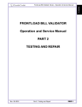
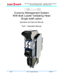
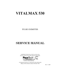
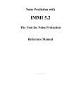
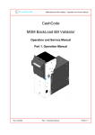
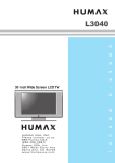
FrontLoad Bill Validator Series - Operation and Service Manual
CashCode
FrontLoad Series
FrontLoad Bill Validator
Operation and Service Manual
Part 1. Operation Manual
Rev. 05-2003
Part 1. Operation Manual
PAGE 1-1
Bill Acceptor FL Series Service Manual
Table of Contents
INTRODUCTION .............................................................................................................. 1-3
PRODUCT OVERVIEW ................................................................................................... 1-4
GENERAL SPECIFICATIONS ........................................................................................ 1-7
DIMENSIONS ................................................................................................................... 1-9
GENERAL WIRING DIAGRAM ..................................................................................... 1-15
MODULAR SYSTEM ..................................................................................................... 1-16
CHOOSING PART NUMBERS FOR THE BILL VALIDATOR ....................................... 1-28
INSTALLATION.............................................................................................................. 1-29
INTERFACE CONNECTION .......................................................................................... 1-35
SWITCH SETTINGS ...................................................................................................... 1-38
MAINTENANCE & SERVICE ........................................................................................ 1-41
SOFTWARE UPDATES ................................................................................................. 1-43
TROUBLESHOOTING ................................................................................................... 1-47
TECHNICAL SUPPORT ................................................................................................ 1-55
page 1-2
Part 1. Operation Manual
Rev. 05-2003
FrontLoad Bill Validator Series - Operation and Service Manual
Congratulations! You have selected one of the most innovative cash-handling devices
of its kind in the world – CashCode’s new generation of high-security FrontLoad bill validators.
The FrontLoad bill validator is the reliable choice for your cash-handling needs, featuring an easyaccess clamshell design and a beltless, roller-based money transport system.
CashCode’s FrontLoad bill validator allows you to easily upgrade sensors and software, install highcapacity cassettes, validate multi-width currencies and rely on the most effective securitytechnology
in the industry.
This manual is designed to give you an easy overview of installation, use, and device upgrades for
CashCode’s line of FrontLoad bill validators.
Rev. 05-2003
Part 1. Operation Manual
PAGE 1-3
INTRODUCTION
INTRODUCTION
Bill Acceptor FL Series Service Manual
PRODUCT OVERVIEW
CashCode’s FrontLoad bill validator was developed to validate a wide variety of currencies. The
unit’s modular design provides extreme flexibility, allowing you to customize the bill validator to suit
your individual requirements.
The CashCode FrontLoad bill validator provides front access to a lockable cassette.
page 1-4
Part 1. Operation Manual
Rev. 05-2003
FrontLoad Bill Validator Series - Operation and Service Manual
The FrontLoad bill validator consists of six main modules. Each module is available in different
variations, to suit your needs. The picture below illustrates the different modules.
Memory Card (for software update)
PRODUCT
OVERVIEW
Validating Head
Bezel (CashCode Standard Bezel is shown)
Housing (for 600 Cassette
with Lock Bracket is shown)
Power Interface Module
Cassette (600 bills cassette is shown)
Rev. 05-2003
Part 1. Operation Manual
PAGE 1-5
Bill Acceptor FL Series Service Manual
The FrontLoad bill validator is designed accommodate bills of different sizes from 62 to 82 mm width,
and from 125 to 172 mm length – which encompasses most currencies.
Certain currencies have different widths depending on denomination. For accurate validation of such
currencies, the Validating Head with a centering mechanism should be used. For currencies of a
fixed-width, the Validating Head with a fixed-width path can be used.
Replaceable “Sense-a-Click™” sensor pak modules recognize and validate a specific currency,
depending on the hardware installed in the sensor pak. The Power Interface module offers different
interface options. The lockable-removable Cassette is used for temporary storage of validated bills. It
can be locked with two standard ¾” tubular locks . The Cassette is available in two sizes: 600 or 1000
bill capacity.
Sense-a-Click
(upper)
Sense-a-Click
(lower)
The Validating Head carries a set of Sense-a-Click™ sensor pak modules
Bill Capacity (600 or 1000 bills) refers to the amount of new bills that the Cassette can store. This
amount of street grade bills may not be stored, due to their greater space requirement. The Housing
joins all the other modules. Housing is permanently secured inside a Gaming or Vending machine.
There may be a mechanism for locking the Cassette within the Housing (Lock Bracket), or there
may be a Plain Bracket. The Housing also contains security switches, which detect Cassette removal. Several Bezel styles are available for the FrontLoad. Software updates can be easily completed with a Memory Card.
This modular design of the FrontLoad validator allows for replacement of failed modules in the field –
in just seconds!
page 1-6
Part 1. Operation Manual
Rev. 05-2003
FrontLoad Bill Validator Series - Operation and Service Manual
GENERAL SPECIFICATIONS
Acceptance:
Bills............................................................................................................lengthwise 4 ways
Barcoded Coupons.....................................................................................two ways, face up
Validation rate..........................................................................96% or higher on first insertion
Width of bill, in mm............................................................................................from 62 to 82
Maximum length of bill, in mm...........................................................................................172
Minimum length of bill, in mm............................................................................................124
Bill escrow...................................................................................................................one bill
GENERAL
SPECIFICATION
Barcoded Coupon specifications:
Encoding standard................................................ANSI/AIM BC2-1995, Uniform Symbology
Specification - Interleaved 2 of 5
Narrow bar width, in mm..........................................................................................0.5 to 0.6
Wide/Narrow Bar Ratio .....................................................................................................3:1
Number of characters..................................................................................................6 to 18
PCS Value (Print Contrast Signal)..............................................................................0.6 min
Time of identificaion, in seconds....................................................................................2.5
(from time of bill insertion to time that credit is issued, in seconds)
Full validation time, in seconds:
Multi-width rontLoad...........................................................................................................4.5
FrontLoad...........................................................................................................................3.5
External interface:
a. Serial Interface, Opto-Isolated.
b. Serial Interface, RS 232C.
c. Isolated Pulse Low Current.
Smart Card (for bill validator with a Smart Card bezel):
Smart Card standard...............................................EMV2000L1 and/or ISO 7816 compatible
Number of supporting payment systems..............................................up to 4 simultaneously
Maximum stacking capacity of new bills in Cassette........................................600 or 1000
Power supply voltage*.............................................................................12 V.D.C. ± 1.0 V
.
or 24 V.D.C. ± 4.0 V
Current consumption*:
Operating mode (max)........................... ...................................................................... 2.0 A
Standby.......................................................................................................................... 0.2 A
Power consumption*, W:
Idle mode.......................................................................................................................2.4 W
Validation mode..............................................................................................................12 W
(* for validator without active light bezel)
Rev. 05-2003
Part 1. Operation Manual
PAGE 1-7
Bill Acceptor FL Series Service Manual
GENERAL SPECIFICATIONS (continue)
Environment:
a. Operating Temperature............................................................................... 0 ºC to +50 ºC
b. Storage Temperature................................................................................. -5 ºC to +60 ºC
c. Humidity (non-condensing)........................................................................... 30%-90%RH
page 1-8
Part 1. Operation Manual
Rev. 05-2003
FrontLoad Bill Validator Series - Operation and Service Manual
DIMENSIONS
Rev. 05-2003
VIEW A
VIEW D
VIEW B
DIMENSIONS
VIEW C
BILL VALIDATOR WITH STANDARD BEZEL, 600 BILL CASSETTE AND LOCKING MECHANISM
Part 1. Operation Manual
PAGE 1-9
Bill Acceptor FL Series Service Manual
VIEW C
VIEW A
C
A
C
VIEW D
BILL VALIDATOR WITH STANDARD BEZEL, 600 BILL CASSETTE AND NON-LOCKING
MECHANISM
page 1-10
Part 1. Operation Manual
Rev. 05-2003
FrontLoad Bill Validator Series - Operation and Service Manual
Rev. 05-2003
VIEW A
PUSH IN
VIEW C
A
VIEW B
B
DIMENSIONS
VIEW D
BILL VALIDATOR WITH STANDARD BEZEL, 1000 BILL CASSETTE AND LOCKING MECHANISM
Part 1. Operation Manual
PAGE 1-11
Bill Acceptor FL Series Service Manual
PUSH IN
VIEW A
A
BILL VALIDATOR WITH STANDARD BEZEL, 1000 BILL CASSETTE AND NON- LOCKING
MECHANISM
page 1-12
Part 1. Operation Manual
Rev. 05-2003
FrontLoad Bill Validator Series - Operation and Service Manual
DIMENSIONS
BILL VALIDATOR WITHOUT BEZEL, 600 BILL CASSETTE AND LOCKING MECHANISM
Rev. 05-2003
Part 1. Operation Manual
PAGE 1-13
Bill Acceptor FL Series Service Manual
VIEW A
VIEW B
BILL VALIDATOR WITH SMART CARD READER, 600 BILL CASSETTE AND LOCKING
MECHANISM
page 1-14
Part 1. Operation Manual
Rev. 05-2003
FrontLoad Bill Validator Series - Operation and Service Manual
GENERAL WIRING
DIAGRAM
GENERAL WIRING DIAGRAM
Rev. 05-2003
Part 1. Operation Manual
PAGE 1-15
Bill Acceptor FL Series Service Manual
MODULAR SYSTEM
A Modular System is an interchangeable group of parts – easily configured to a user’s specifications.
Below is a more detailed description of each module and its features.
VALIDATING HEAD
The Validating Head has the following options:
1)
The Validating Head with a fixed-width path is available for bill widths 62, 64, 66, 68, 70, 72,
74, 76, 78, 80 and 82 mm.
2)
The Validating Head with a centering mechanism has a self-adjustable bill path. The width
of the path is automatically adjusted to accommodate each bill. This type of Validating
Head is used for currencies where the width of the bill changes with the denomination.
page 1-16
Part 1. Operation Manual
Rev. 05-2003
FrontLoad Bill Validator Series - Operation and Service Manual
3) The “Model” of Validating Head reflects the type of electronics used within, and determines the
compatibility with other modules.
Model
FLV-0110
Bi ll wi dth 62 mm
A
FLV-0210
Bi ll wi dth 64 mm
A
FLV-0310
Bi ll wi dth 66 mm
A
FLV-0410
Bi ll wi dth 68 mm
A
FLV-0510
Bi ll wi dth 70 mm
A
FLV-0610
Bi ll wi dth 72 mm
A
FLV-0710
Bi ll wi dth 74 mm
A
FLV-0810
Bi ll wi dth 76 mm
A
FLV-0910
Bi ll wi dth 78 mm
A
FLV-1010
Bi ll wi dth 80 mm
A
FLV-1110
Bi ll wi dth 82 mm
A
Multi -wi dth
A
MFLV-2110
Rev. 05-2003
D escription
Part 1. Operation Manual
Availability
yes
yes
MODULAR
SYSTEM
Part
N umber
yes
PAGE 1-17
Bill Acceptor FL Series Service Manual
Listed below are the Validating Heads for different countries.
C o u n try (c u rre n c y )
A r g e nt i na
FLV-0310
A us t r a l i a
FLV-0310
A us t r i a
MFLV-2110
B r a zi l
FLV-0310
C a na d a
FLV-0510
C hi l e
FLV-0510
C hi na
MFLV-2110
C o lo mb i a
FLV-0510
D o m i ni c a n R e p ub l i c
FLV-0310
E ur o p e a n U ni o n ( E ur o )
MFLV-2110
Gre a t B ri ta i n
MFLV-2110
H o ng K o ng
MFLV-2110
Japan
MFLV-2110
K o re a
MFLV-2110
M e xi c o
FLV-0310
N e w Ze a l a nd
P hi l i p p i ne s
MFLV-2110
FLV-0310
R us s i a
MFLV-2110
S c o t l a nd
MFLV-2110
S o ut h A f r i c a
U k r a i ne
FLV-0510
MFLV-2110
US A
FLV-0310
U S A + C a na d a
MFLV-2110
U S A + M e xi c o
FLV-0310
V e ne zue l a
FLV-0510
K a za k hs t a n
page 1-18
Validating Head part number
MFLV-2110
Part 1. Operation Manual
Rev. 05-2003
FrontLoad Bill Validator Series - Operation and Service Manual
SENSE-A-CLICK® MODULES
“Sense-a-Click™” sensor paks are a set of two modules – one upper and one lower. In order to be
compatible with each other, both modules must have the same part and model number.
The Sense-a-Click™ set is identified by:
- Color and position of the optical sensors;
- Number and position of the Inductive sensors;
- Capacitive sensors;
- Model, which reflects the type of electronics housed within, and determines the
compatibility with other modules.
Depending on the bill type, the following Sense-a-Click™ part numbers are used:
Part Number for Sense-a-Click Sensor Paks
Set of tw o
modules
U p p er
module
Low er module
Model
Argentina
AR
FLS-1704
FLS-1704U
FLS-1704L
A
Australia
AU
FLS-1704
FLS-1704U
FLS-1704L
A
Brazil
BR
FLS-1704
FLS-1704U
FLS-1704L
A
Canada
CA
FLS-1801
FLS-1801U
FLS-1801L
A
Chile
CL
FLS-1704
FLS-1704U
FLS-1704L
A
China
CN
FLS-1705
FLS-1705U
FLS-1705L
A
Colombia
CO
FLS-1704
FLS-1704U
FLS-1704L
A
Dominican Republic
DO
FLS-1704
FLS-1704U
FLS-1704L
A
European Union (Euro)
EU
FLS-1704
FLS-1704U
FLS-1704L
A
Great Britain
GB
FLS-1704
FLS-1704U
FLS-1704L
A
Hong Kong
HK
FLS-1705
FLS-1705U
FLS-1705L
A
Mexico
MX
FLS-1705
FLS-1705U
FLS-1705L
A
New Zealand
NZ
FLS-1704
FLS-1704U
FLS-1704L
A
Philippines
PH
FLS-1704
FLS-1704U
FLS-1704L
A
Russia
RU
FLS-1704
FLS-1704U
FLS-1704L
A
South Africa
ZA
FLS-1704
FLS-1704U
FLS-1704L
A
Ukraine
UA
FLS-1704
FLS-1704U
FLS-1704L
A
USA
US
FLS-1704
FLS-1704U
FLS-1704L
A
USCA
FLS-1901
FLS-1901U
FLS-1901L
A
Venezuela
VE
FLS-1705
FLS-1705U
FLS-1705L
A
Scotland
SL
FLS-1704
FLS-1704U
FLS-1704L
A
USA + Mexico
USMX
FLS-1704
FLS-1704U
FLS-1704L
A
USA + Great Britain
USGB
FLS-1704
FLS-1704U
FLS-1704L
A
China+ Hong Kong
CNHK
FLS-1705
FLS-1705U
FLS-1705L
A
KZ
FLS-1704
FLS-1704U
FLS-1704L
A
USA + Canada
Kazakhstan
Rev. 05-2003
Part 1. Operation Manual
Upper Module
MODULAR
SYSTEM
Currency
Lower Module
PAGE 1-19
Bill Acceptor FL Series Service Manual
POWER INTERFACE MODULE
The Power Interface Module offers the following options:
1) Input power: 12 VDC or 24 VDC;
2) Interface (see chart below for complete list of interfaces);
3) Model: reflects type of electronics within (A – with linear voltage regulation, B – with switching
voltage regulation). Model B provides higher power and must be used when additional modules are
included in the FrontLoad Bill Validator (e.g. Smart Card Reader)
4) Connector for Cassette Touch Memory (Dallas Chip) – a system which helps manage cash
flow and collects statistics from the Bill Validator.
Part Number
page 1-20
P o w er
Interface
Model Touch Memory Connector
FLP-1710
12 VDC CC-FLBDP (Opto-isolated)
A
No
FLP-2710
12 VDC CC-BDPS, CCNET (RS 232C)
A
No
FLP-2810
12 VDC CC-IPL (Isolated Pulse Low Current)
A
No
FLP-5710
24 VDC CC-GPC22, CCNET (RS 232C)
B
No
Part 1. Operation Manual
Rev. 05-2003
FrontLoad Bill Validator Series - Operation and Service Manual
HOUSING
Housing offers the following options:
1) Size of supporting bracket: 2 sizes are available – 600 bill Cassettes and 1000 bill Cassettes;
2) Locking mechanism in supporting bracket: Lockable bracket and Plain bracket are available.
Locking mechanism can operate with a ¾” tubular lock.
3) Security switches. Housing is equipped with a “Cassette removal” security switch and, if the
Lockable bracket option was selected, with an “Open lock” security switch. Both switches have
Quick Connect terminals (0.110) and are rated for 5A at 250 VAC. Optionally, a second switch for the
Cassette, and a Switch for the Validating Head can be added.
4) Interface connectors: JAE 12 pin (standard), JAE + DB9 (use with Card Reader Bezel), JAE
+ USB.
Housing for 1000
bill cassette
without Locking
mechanism.
MODULAR
SYSTEM
Housing for 600
bill Cassette with
Locking mechanism.
The following combination of features described above are available:
Cassette
siz e
Bracket
Optional security
sw itches
Connectors
FLH-0110
600
Plain
None
Standard
FLH-0410
600
Lockable
None
JAE+DB9
FLH-0510
600
Plain
None
JAE+DB9
FLH-0810
600
Lockable
None
Standard
FLH-3110
1000
Plain
None
Standard
FLH-3410
1000
Lockable
None
JAE+DB9
FLH-3510
1000
Lockable
None
Standard
FLH-2010
1000
Plain
None
JAE+DB9
Part Number
Rev. 05-2003
Part 1. Operation Manual
PAGE 1-21
Bill Acceptor FL Series Service Manual
BEZELS
Part Number
Bill width, in mm
Several Bezel designs are available in order to make the
CashCode Bill Validator compatible with different door
styles. Normally, the Bill Validator is supplied with the
Standard CashCode Bezel. Each type of bezel is available
for different bill path widths (path width for the bezel and
Validating Head must be the same).
CashCode Standard Bezel
FLB-2301
62 and 64
FLB-2311
66
FLB-2321
68
FLB-2331
70
FLB-2341
72
FLB-2351
74
FLB-2361
76
FLB-2371
78
FLB-2381
80
MFLB-2401
62 to 82
Standard CashCode Bezel. The status indication
light is provided.
Status light
CashCode Bezel with runway lights
FLB-2101
62 and 64
FLB-2111
66
FLB-2121
68
FLB-2131
70
FLB-2141
72
FLB-2151
74
FLB-2161
76
FLB-2171
78
FLB-2181
80
MFLB-2201
62 to 82
Runway lights
CashCode Bezel with Digital Display
FLB-3101
62 and 64
FLB-3111
66
FLB-3121
68
FLB-3131
70
FLB-3141
72
FLB-3151
74
FLB-3161
76
FLB-3171
78
FLB-3181
80
MFLB-3201
62 to 82
page 1-22
CashCode Bezel with running lights. The status
light is combined with runway lights.
CashCode Bezel with runway lights and digital
display. In addition to runway lights, a digital display of
2 lines (16 characters each) is provided. Users are
able to create a custom message – in order to attract
or instruct customers.
Digital display
Part 1. Operation Manual
Rev. 05-2003
FrontLoad Bill Validator Series - Operation and Service Manual
Part Number
Bill width, in mm
CashCode Bezel with runway lights and IR
communication port
FLB-2501
62 and 64
FLB-2511
66
FLB-2521
68
FLB-2531
70
FLB-2541
72
FLB-2551
74
FLB-2561
76
FLB-2571
78
FLB-2581
80
MFLB-2601
62 to 82
IR communication port
62 and 64
FLB-3311
66
FLB-3321
68
FLB-3331
70
FLB-3341
72
FLB-3351
74
FLB-3361
76
FLB-3371
78
FLB-3381
80
MFLB-3401
62 to 82
Rev. 05-2003
CashCode Bezel with runway lights, digital
display and Infrared communication port. In
addition to runway lights and a digital display, an IR
communication port is provided.
MODULAR
SYSTEM
CashCode Bezel with Digital Display and an IR
communication port
FLB-3301
CashCode Bezel with runway lights and Infrared
communication port. In addition to runway lights,
an IR communication port is provided.
IR communication port
Part 1. Operation Manual
PAGE 1-23
Bill Acceptor FL Series Service Manual
Part Number
Bi ll wi dth, i n mm
Smart C ard Reader wi th Infrared
communi cati on port
FLB-4401
62 and 64
FLB-4411
66
FLB-4421
68
FLB-4431
70
FLB-4441
72
FLB-4451
74
FLB-4461
76
FLB-4471
78
FLB-4481
80
MFLB-4501
CashCode Bezel with Smart Card reader.
The Card Reader can support up to 4 different
payment systems simultaneously.
Runway lights
Digital display
62 to 82
Slot for Smart Card
Infrared communication port
CashCode Bezel for “Double Diamond”
Gaming machine. Available in two widths: 66
and 70 mm.
Part Number
Bill width, in mm
FLB-1011
66
FLB-1021
70
page 1-24
Part 1. Operation Manual
Rev. 05-2003
FrontLoad Bill Validator Series - Operation and Service Manual
ACCESSORIES
Accessories, typically supplied with the Bill Validator, include an extractor (a special tool for replacing
the Sense-a-Click® sensor pak Lower module, part number OPT-HW-FT01) and a harness (cable)
for external connections.
OPT-HW-FT01
If no special requirements have been indicated, then the cable will automatically come with 12
“loose” wires at one side and a 12-pin JAE connector attached to the other side. The total length of
cable is 1 meter. The chart below gives information about wire color and connection to the connector pin.
The harness part number is FL-HS-JAE-05.
A customized harness is also available, to suit your special needs.
C olor of wi re
1
Red
2
Brown
3
Yellow
4
Black
5
Blue
6
Gray
7
Pi nk
8
Orange
9
Green
Not connected
Tan
11
Vi olet
12
Whi te
MODULAR
SYSTEM
C onnector pi n No.
For a download via the interface connector, the following accessories must be used:
Power Interface Module
used i n FrontLoad Bi ll
Vali dator
Adapter part
number
Interface
FLP-1710
OPT-PS2-FL-PC
C C -FLBD P
FLP-2710
FLP-2810
FLP-5710
Rev. 05-2003
OPT-PS2-JAE-D B 9
comi ng soon
FL-BD PS, C C NET (12V)
C C -IPL
C C -GPC 22, C C NET (24V)
Part 1. Operation Manual
PAGE 1-25
Bill Acceptor FL Series Service Manual
CASSETTE
The Cassette stores validated bills and holds them in a stacked formation. The Cassette has
a stacking mechanism and is typically equipped with a plastic lock. Users are encouraged to
replace the plastic lock with a regular metal one. Users have a choice between one lock – or
two locks for added security. A locking mechanism allows for the installation of a user’s security locks (one or two 3/4” tubular locks measuring 11/16”±1/16” or 11/8”±1/16”).
The Cassette is available in two sizes – either a 600 and 1000 bill storage capacity. Street
grade bills require more space and as a result, less bills may be stored. The Cassette is
supplied with a foldable handle, but where space inside the machine is limited, a Cassette may
be ordered without a handle.
The Cassette can store bills from 62 to 82 mm wide, and from 140 to 172 mm long. For
bills from 125 to 150 mm in length, a modified Cassette may be ordered.
The Cassette may be ordered with mounting parts for installation of the Touch Memory
(Dallas Chip). The proper type of Power Interface Module must be ordered to communicate
with the Dallas Chip.
The Cassette is not included with the Bill Validator and must be ordered separately.
Foldable Handle
Dallas Chip
Locks
600 bill cassette
The following types of cassettes are available:
Part No.
Cassette
capacity, bills
Bill length,
mm
Handle
Dallas
Chip
FLC-003
600
125 to 150
Foldable
no
FLC-103
600
140 to 172
Foldable
no
FLC-503
1000
125 to 150
Foldable
no
FLC-603
1000
140 to 172
Foldable
no
For other cassettes, please contact CashCode.
page 1-26
Part 1. Operation Manual
1000 bill cassette
Rev. 05-2003
FrontLoad Bill Validator Series - Operation and Service Manual
MEMORY CARD AND SOFTWARE UPDATE OPTIONS
CashCode FrontLoad Bill Validators are supplied with pre-installed software, according to user’s
order. A “Dummy Card” is normally placed in the slot instead of a Memory Card. Software updates
are recommended whenever new currency is issued, or whenever a new series of counterfeit bills
appear on the market.
Software updates are offered in three options:
1)New software can be ordered with a single-download Memory Card. The software from the
new Memory Card is downloaded as soon as it is inserted into the slot, and the Validating Head is
powered on. The Memory Card must be present at all times for the Bill Validator to operate.
2)New software can be ordered with a multi-download Memory Card. The multi-download
Memory Card allows the operation of the FrontLoad Bill Validator without the Memory Card. Thus the
Memory Card can be used for updating the next FrontLoad Bill Validator, depending on the number of
licences ordered. Typically a multi-download Memory Card is issued for a limited number of downloads, and therefore the number of licences required must be defined in the user’s order.
3)A special Memory Card can be ordered, which allows the download of new software through
the interface connector. After the download, the Memory Card must be present in the Validating
Head at all times. If the host controller supports the CCNET interface, then the download can be
done via the host controller (and local network). Other interfaces do not support this download
feature. Downloads in this case can be completed with any personal computer (PC or laptop) and a
CashCode adapter. (The Validator must be temporarily disconnected from the host controller).
MODULAR
SYSTEM
Instructions for Memory Card replacement and software updates can be found in the chapter
called “SOFTWARE UPDATES” on page 43.
Rev. 05-2003
Part 1. Operation Manual
PAGE 1-27
Bill Acceptor FL Series Service Manual
CHOOSING PART NUMBERS FOR THE BILL VALIDATOR
Final part numbers for the FrontLoad Bill Validator consist of two parts: a hardware part number and
a software part number.
Example:
MFL-0101US1701
Software part number
Hardware part number
Prefix (FL for FrontLoad, or
MFL Multi-width FrontLoad)
The Prefix defines the device class. Here FL means “FrontLoad Bill Validator” and MFL means “Multiwidth Front Load Bill Validator” (i.e. with a centering mechanism in the Validating Head).
The Hardware part number reflects the contents of the Bill Validator (i.e. Validating Head type,
Housing type, etc.)
The Software part number reflects country (currency) and communication protocol.
There is a special software program for choosing part numbers. (Please see the enclosed CDROM program entitled “CONFIGURATOR.exe”.)
Before the user starts this program, the following information must be determined:
- Country (e.g. USA);
- Protocol (e.g. CCNET)
- Power (e.g. 12VDC)
- Type of Bezel (e.g. Standard)
- Housing options (ie: Cassette size, locking mechanism, additional cassette security switch)
When the program runs, menus will appear with all available options, including a comprehensive
help menu with detailed description and pictures.
Please keep in mind that Cassettes must be ordered separately. At least one Cassette per Bill
Validator will be needed, but the user may order additional quantities of Cassettes (ie: to switch
Cassettes when collecting money).
In cases where the combination of features selected by the user is not possible, the user will
receive a message that the part number does not exist – and a letter to the CashCode Engineering
department will be generated. This system was choosen because the total number of all possible
part combinations can reach up to 70,000! As a result, part numbers are assigned gradually when
an actual request is received.
page 1-28
Part 1. Operation Manual
Rev. 05-2003
FrontLoad Bill Validator Series - Operation and Service Manual
INSTALLATION
The Bill Validator is installed by using (3) M4 screws on each side of the FrontLoad frame. The
length of these screws should not be longer than required, otherwise they may protrude through the
inside of the frame.
If the position of the mounting screws is different than the position of the mounting holes provided in
the target equipment, then additional frame mounting components may be required.
The FrontLoad Bill Validator can also
be secured through the holes in the
rear wall of the Housing. In this
case, M3 screws and locator pins
can be used.
INSTALLATION
For dimensions of the mounting
holes, please refer to the dimensional drawings (page 8 to 13).
Four screws M3, Pan Head
Two locator pins
Rev. 05-2003
Part 1. Operation Manual
PAGE 1-29
Bill Acceptor FL Series Service Manual
LOCK INSTALLATION TO BILL VALIDATOR BASE (600 BILLS)
Step #1. Remove the Screw and Lock Washer from the Lock Cover. DO NOT DISCARD!
(FIG. 1)
Step #2. Remove and discard the Washer and Spacer (FIG. 1)
Step #3. Install the Lock and parts as shown in FIG. 2
Step #4. Reinstall the Cover, Screw and Lock Washer that were removed in Step #1 (see Fig.3)
Screw M3x16, Pan Head, Zinc
(8201955)
Lock Washer M3,
Internal Tooth, Zinc
(8203002)
COVER ASS'Y
(0100186)
FL HOUSING
Parts for transportation only,
to be removed when lock installed
Steel Flat Washer
SPAENAUR No 656-057
(8203999)
"BUTTite" Rolled Spacer
SPAENAUR No 607-070
(8208998)
Parts belonging to the lock assembly
HEX NUT
WASHER
CAM
(5110049)
A=from 5/ 8 " to 1 1/ 8"
NUT
WASHER
KEY
page 1-30
COVER
(0100186)
WASHER
(5110035)
LOCK
Part 1. Operation Manual
Rev. 05-2003
FrontLoad Bill Validator Series - Operation and Service Manual
LOCK INSTALLATION TO BILL VALIDATOR BASE (600 BILLS) (continued)
Screw M3x16, Pan Head, Zinc
(8201955)
Lock Washer M3,
Internal Tooth, Zinc
(8203002)
INSTALLATION
FL HOUSING
Rev. 05-2003
Part 1. Operation Manual
PAGE 1-31
Bill Acceptor FL Series Service Manual
LOCK INSTALLATION TO BILL VALIDATOR BASE (1000 BILLS)
Step #1. Remove the Screw and Lock Washer from the Lock Cover. DO NOT DISCARD!
(FIG. 1)
Step #2. Remove and discard the Washer and Spacer (FIG. 1)
Step #3. Install the Lock and parts as shown in FIG. 2
Step #4. Reinstall the Cover, Screw and Lock Washer that were removed in Step #1 (see FIG. 3)
Lock Washer M3,
Internal Tooth, Zinc
(8203002)
Screw M3x16,
Pan Head, Zinc
(8201955) (3 pcs.)
COVER ASS'Y
(0100204)
Parts for transportation only,
to be removed when lock installed
Steel Flat Washer
SPAENAUR No 656-057
(8203999)
"BUTTite" Rolled Spacer
SPAENAUR No 607-070
(8208998)
Parts belonging to the lock assembly
HEX NUT
WASHER
CAM
(5110049-01)
A=from 5/ 8" to 1 1/ 8"
NUT
WASHER
KEY
page 1-32
COVER
(0100186)
WASHER
(5110035)
LOCK
Part 1. Operation Manual
Rev. 05-2003
FrontLoad Bill Validator Series - Operation and Service Manual
LOCK INSTALLATION TO BILL VALIDATOR BASE (1000 BILLS) (continued)
Lock Washer M3,
Internal Tooth, Zinc
(8203002)
Screw M3x16,
Pan Head, Zinc
(8201955) (3 pcs.)
INSTALLATION
FL HOUSING
Rev. 05-2003
Part 1. Operation Manual
PAGE 1-33
Bill Acceptor FL Series Service Manual
LOCK INSTALLATION TO CASSETTE
In order to install the security locks into the Cassette, open the Cassette cover, remove the plastic
lock and plug, and follow the diagram shown below:
DIA22.2max
12.7max
page 1-34
A
A=11 16"± 1 16"
or
A=11 8"± 1 16"
B
Adjust size B
with Washers
within 0.6875±0.01"
or 1.125±0.01"
Part 1. Operation Manual
Rev. 05-2003
FrontLoad Bill Validator Series - Operation and Service Manual
INTERFACE CONNECTION
The FrontLoad Bill Validator has the flexibility to offer four different hardware interface options:
Type 1: Opto-Isolated, 12 Volt CC FLBDP.
Type 2: RS232 levels, 12 Volt CCNET (single slave mode) or CC-BDPS.
Type 3: Isolated Pulse Low Current, 12 Volt CC-IPL.
Type 4: RS232 levels, 24 Volt DC, CCNET (single slave mode) or CC-GPC22.
For detailed interface descriptions, please refer to the corresponding Interface Description Manual.
The manual may be downloaded from the CashCode website at www.cashcode.com .
The type of interface hardware depends on the base assembly interface module.
Pin Assignment (cable connector):
Socket DR1-12-2SC-FO (JAE)
Contact DR-SC20-1-7000 (JAE)
Rev. 05-2003
TER MIN AL
SIGN AL
FU N C TION
AC TIVITY
1
+12 V D C
POWER
---
2
M-RES
MASTER RESET
LOW
3
+12V D C
INTERFAC E POWER
---
4
GND
INTERFAC E GROUND
---
5
LE D +
LED ANOD E
---
6
NC
NOT C ONNEC TED
---
7
GND
POWER GROUND
---
8
TXD
TRANSMITTED D ATA
HIGH/LOW
9
RXD
REC EIVED D ATA
HIGH/LOW
10
NC
NOT C ONNEC TED
---
11
LE D -
LED C ATHOD E
---
12
NC
NOT C ONNEC TED
---
Part 1. Operation Manual
INTERFACE
CONNECTION
Signal descriptions for the Opto-isolated version (Type1):
PAGE 1-35
Bill Acceptor FL Series Service Manual
Signal Descriptions for the RS232 12Volt version (Type2, Type3)
TE R MIN AL
S IGN AL
FU N C TION
1
+12V D C
P OWE R
2
M-RE S
MA S TE R RE S E T
3
NC
NOT C ONNE C TE D
4
GND
INTE RFA C E GROUND
5
NC
NOT C ONNE C TE D
6
NC
NOT C ONNE C TE D
7
GND
GROUND P OWE R
8
TxD
TRA NS MITTE D D ATA
9
RxD
RE C E IV E R D ATA
10
NC
NOT C ONNE C TE D
11
NC
NOT C ONNE C TE D
12
NC
NOT C ONNE C TE D
AC TIVITY
LOW
HIGH/LOW
HIGH/LOW
-
Signals Description for RS232 24 Volt version (Type4):
page 1-36
TE R MIN AL
S IGN AL
FU N C TION
1
GND
GROUND P OWE R
2
M-RE S
MA S TE R RE S E T
3
NC
NOT C ONNE C TE D
4
GND
GROUND INTE RFA C E
5
NC
NOT C ONNE C TE D
6
NC
NOT C ONNE C TE D
7
+24V D C
P OWE R
8
TxD
TRA NS MITTE D D ATA
9
RxD
RE C E IV E R D ATA
10
NC
NOT C ONNE C TE D
11
NC
NOT C ONNE C TE D
12
NC
NOT C ONNE C TE D
Part 1. Operation Manual
AC TIVITY
LOW
HIGH/LOW
HIGH/LOW
-
Rev. 05-2003
FrontLoad Bill Validator Series - Operation and Service Manual
RST-BDP
RXD-BDP
+12V-BDP
PWR-LED
TXD_BDP
GND-BDP
LED-BDP
INPUT/OUTPUT CIRCUITS OPTO-ISOLATED VERSION
C14
R14
R12
R10
R13
R11
VCC
VD4
VD5
C15
VE4
VE5
1
VD6
3
6
VCC
VCC
4
VD3
5
R8
1
2
4
3
R9
GND
C24
GND
PC400
PC357NT
VE3
MC74HC132AD
6
PC400
&
MC74HC132AD
VT4
11
GND
DD1D
RST
DD1B
3
&
1
13
4
6
12
GND
5
5
4
GND
R5
R4
2
1
5.1K
DD1A
VCC
MC74HC132AD
VT2
R3
&
3
VCC
GND
GND
BRST
L1
L2
L3
CYCL
TMD
BOX
RXD
TXD
DIRECT
PM-EN
BRST
LED
LED
RXD
VCC
TXD
VCC
VT8
C23
L1
L2
LED-BDP
PWR-LED
L3
GND-BDP
RXD-BDP
+12V-BDP
TXD-BDP
RST-BDP
VT1
C22
VCC
C21
+12V
GND
+12V
Power -
GND
1
20
2
21
3
22
4
23
5
24
6
25
7
26
8
27
9
28
10
29
11
30
12
31
13
32
14
33
15
34
16
35
17
36
18
37
19
Power +
No.747843-4
1
2
3
4
5
6
7
8
9
10
11
12
INTERFACE
CONNECTION
1
20
2
21
3
22
4
23
5
24
6
25
7
26
8
27
9
28
10
29
11
30
12
31
13
32
14
33
15
34
16
35
17
36
18
37
19
CONNECTOR DB37
12 JAE HEADER
Rev. 05-2003
Part 1. Operation Manual
PAGE 1-37
Bill Acceptor FL Series Service Manual
SWITCH SETTINGS
The switches are located at the rear of the Validating Head, under the transparent cover.
Validating Head
Setting switches
SW1
SW2
The Bill Validator operates in two basic modes: Validation Mode and Service Mode.
Validation Mode: This is the mode for normal operation. If a red status light is illuminated, it
indicates that the validator is not ready to accept currency.
Service Mode: This is the mode for programming and testing the CashCode Bill Validator.
page 1-38
Part 1. Operation Manual
Rev. 05-2003
A series of (8) position DIP switches (SW1) define the settings and program the Bill Validator to
recognize and validate a variety of different bill denominations.
ON State of switch
OFF State of switch
DIP SWITCH SW1 SETTINGS:
SWITC H
ON
OFF
SW1.1
D enomi nati on #1 Enable
D enomi nati on #1 D i sable
SW1.2
D enomi nati on #2 Enable
D enomi nati on #2 D i sable
SW1.3
D enomi nati on #3 Enable
D enomi nati on #3 D i sable
SW1.4
D enomi nati on #4 Enable
D enomi nati on #4 D i sable
SW1.5
D enomi nati on #5 Enable
D enomi nati on #5 D i sable
SW1.6
D enomi nati on #6 Enable
D enomi nati on #6 D i sable
SW1.7
D enomi nati on #7 Enable
D enomi nati on #7 D i sable
SW1.8
D enomi nati on #8 Enable
D enomi nati on #8 D i sable
For a complete explanation of switch descriptions, please see the software version
description.
Rev. 05-2003
Part 1. Operation Manual
PAGE 1-39
SWITCH
SETTING
FrontLoad Bill Validator Series - Operation and Service Manual
Bill Acceptor FL Series Service Manual
The (4) position DIP switches (SW2) are defined below:
ON State of switch
OFF State of switch
PAR AMETER
SWITC H
ON
OFF
Orientation of the bill
SW2.1
Four-Way
One-Way
SW2.2
Reserved
Reserved
Interface communication
sp eed
SW2.3
9600 B P s
19200 B P s
Mode
SW2.4
Servi ce Mode
Vali dati on Mode
For additional information on switch features and explanations, please see the software
description for your particular Bill Validator.
page 1-40
Part 1. Operation Manual
Rev. 05-2003
FrontLoad Bill Validator Series - Operation and Service Manual
MAINTENANCE & SERVICE
Collecting Bills
MAINTENANCE
AND SERVICE
To collect bills from the CashCode Bill Validator, simply open the lock on the base assembly and pull
out the Cassette (please see diagram below).
Pressing the lever (located to the right) releases the Cassette for easy removal.
To replace the Cassette, close the Cassette cover, insert the Cassette into the FrontLoad frame,
and turn the key to lock the Cassette back in place.
Rev. 05-2003
Part 1. Operation Manual
PAGE 1-41
Bill Acceptor FL Series Service Manual
To open the Cassette cover, simply open the locks – located on the Cassette cover (as shown in
diagram below).
The Cassette cover will then open easily, and the validated pack of bills can then be removed as a
neat stack.
page 1-42
Part 1. Operation Manual
Rev. 05-2003
FrontLoad Bill Validator Series - Operation and Service Manual
SOFTWARE UPDATES
The FrontLoad Bill Validator is shipped with pre-installed software, according to a user’s ordered
specifications.
To ensure the proper operation of the FrontLoad Bill Validator, software updates can be
ordered according to the original FrontLoad part number.
Download procedure for a single-download Memory Card:
Step 2. Lift up the Latch under the Validating Head, and Remove the Validating Head from the
Housing.
Rev. 05-2003
Part 1. Operation Manual
PAGE 1-43
SOFTWARE
UPDATES
Step 1. Turn Power OFF.
Bill Acceptor FL Series Service Manual
Step 3. Remove the Dummy Card (or Memory Card) from the Memory Card slot of the Validating
Head (please see diagram below).
Step 4. Insert the new CashCode Memory Card into the Memory Card slot of the Validating Head
(please see diagram below).
page 1-44
Part 1. Operation Manual
Rev. 05-2003
FrontLoad Bill Validator Series - Operation and Service Manual
SOFTWARE
UPDATES
Step 5. Insert the Validating Head into the Housing.
Step 6. Turn Power ON and wait until the download process is completed. During the download, a
red-green status light will blink. Once the download is completed, the diagnostic light will turn green.
Should the light stay red, this means there is no communication between the FrontLoad Bill Validator
and the host controller.
STATUS LIGHT
A single-download Memory Card must be present in the Bill Validator at all times.
Download procedure for the multi-download Smart Stick:
Please refer to the instructions concerning the single-download Memory Card. Follow steps 1, 2, 4,
5 and 6. After the successful completion of step 6, follow steps 1, 2, 3 and 5.
The Memory Card can be used to update more units, until the number of licenses is reached.
Rev. 05-2003
Part 1. Operation Manual
PAGE 1-45
Bill Acceptor FL Series Service Manual
Download procedure via interface connector:
In order to properly complete an interface download, the Memory Card must be present in the
Memory Card slot at all times – before and during the download.
1. When the FrontLoad Bill Validator has a CCNET protocol, the software download can be completed
via the host controller (refer to CCNET Protocol Description).
2. For a direct download via the interface connector, please follow the instructions below:
Step 1. Turn power OFF.
Step 2. Disconnect the interface connector from the Bill Validator.
Step 3. Remove the Validating Head from the Housing, and set Mode Switch to Service mode (see
page 36).
Step 4. Install the Validating Head into the Housing.
Step 5. Connect the CashCode Adaptor (see page 23 for exact type): a) to the Computer, b) to the
interface connector of the Bill Validator, and c) to the power outlet (AC 100-250V).
Step 6. From the computer, run the latest software version of the FL***.exe program.
Step 7. Follow the instructions displayed on the computer screen.
Step 8. After completing step 7, disconnect the CashCode Adaptor: a) from the power outlet, b) from
the Bill Validator, and c) from the Computer.
Step 9. Remove the Validating Head from the Housing, and set Mode Switch to Validation mode (see
page 36).
Step 10. Install the Validating Head into the Housing.
Step 11. Connect the interface connector to the Bill Validator.
Step 12. Turn power ON.
SOFTWARE UPDATE DIAGNOSTICS
Normally, the download process will be accompanied by a blinking red-green status light for about 1
minute. If the download has competed successfully, the status light will turn green. Should the
download be unsuccessful, the status light will turn red, but short green flashes of light will alternate
with a long red light (“green flashes on red”).
The following table lists possible errors which may take place during a download:
STATU S OF
D IAGN OSTIC LIGH T
ER R OR D ESC R IPTION
FAU LT - H AN D LIN G
1 GR EEN FLASH ON External i nterface ERROR 1. Veri fy that software i s sui table for C C NET download.
R ED
i n C C NET D ownload mode 2. Repeat procedure.
1. Turn POWER OFF, remove and i nsert the Smart Sti ck agai n, turn
POWER ON.
2. Replace Memory C ard wi th the new one.
2 GR EEN FLASH ES
ON R ED
Memory C ard C RC
ERROR
3 GR EEN FLASH ES
ON R ED
Incorrect data i n Memory
C ard
4 GR EEN FLASH ES
ON R ED
Memory C ard i s not
i nserted
5 GR EEN FLASH ES
ON R ED
Wrong type of Memory
C ard
Insert the correct type of C ashC ode Memory C ard.
6 GR EEN FLASH ES
ON R ED
Fai lure duri ng download
1. Turn POWER OFF, remove and i nsert the Memory C ard agai n, turn
POWER ON.
2. Replace Memory C ard wi th the new one.
7 GR EEN FLASH ES
ON R ED
Operati on ERROR of
Memory C ard i nterface
1. Turn POWER OFF, remove and i nsert the Memory C ard agai n, turn
POWER ON.
2. Replace Memory C ard wi th the new one.
page 1-46
1. Veri fy that the software i s sui table to the Bi ll Vali dator type.
2. Insert correct type of C ashC ode Memory C ard.
Properly i nsert the Memory C ard.
Part 1. Operation Manual
Rev. 05-2003
FrontLoad Bill Validator Series - Operation and Service Manual
TROUBLESHOOTING
CashCode’s FrontLoad Bill Validator is equipped with a self-diagnostic feature to aid in repair and
maintenance. When the power to the Bill Validator is turned ON, the Bill Validator begins its selfdiagnostic operation.
If the self-diagnostic test is passed, then the status light will turn green. If an error is detected, then
the status light on the front of the Bill Validator will blink red.
TROUBLESHOOTING
The number of times the red light flashes on the Bill Validator, is an indication of a specific problem
or malfunction. A detailed list of these errors and corrective action is provided in the Diagnostics
section to follow.
Status light
Rev. 05-2003
Part 1. Operation Manual
PAGE 1-47
Bill Acceptor FL Series Service Manual
OPERATION MODE DIAGNOSTICS
N U MB ER OF
STATU S LIGH T
FLASH ES
ER R OR D ESC R IPTION
FAU LT - H AN D LIN G
1. R E D
C ASSETTE IS
REMOVED FROM BILL
VALID ATOR
C HEC K IF C ASSETTE IS
INSTALLED C ORREC TLY
N OTE
Cassette
page 1-48
Part 1. Operation Manual
Rev. 05-2003
FrontLoad Bill Validator Series - Operation and Service Manual
N U MB ER OF STATU S
ER R OR D ESC R IPTION
LIGH T FLASH ES
N OTE
1. D ISC ONNEC T POWER FROM
VALID ATOR.
2. OPEN C OVER, C HEC K IF
SENSE-A-C LIC K MOD ULES
ARE PROPERLY INSTALLED .
3. VERIFY THAT SENSE-AC LIC K MOD ULES
C ORRESPOND TO THE
C ORREC T SOFTWARE
TYPE/VERSION.
TROUBLESHOOTING
2. R E D
AN ERROR OC C URED
D URING C PU
EXC HANGE WITH
SENSE-A-C LIC K
MOD ULES
FAU LT - H AN D LIN G
EXTRACTOR
OPT-HW-FT01
SENSE-A-CLICK
(Lower Module)
SENSE-A-CLICK
(Upper Module)
GUIDE
(0200052)
GUIDE
(0200053)
Rev. 05-2003
Part 1. Operation Manual
PAGE 1-49
Bill Acceptor FL Series Service Manual
N U MB ER OF
STATU S LIGH T
FLASH ES
ER R OR D ESC R IPTION
3. R E D
C ASSETTE IS FULL
REMOVE C ASSETTE, EMPTY
C ASSETTE AND INSERT
EMPTY C ASSETTE .
MEC HANIC AL JAM
IN C ASSETTE OR
STAC KER MOTOR
FAILURE
1. REMOVE C ASSETTE FROM
BILL VALID ATOR HOUSING
AND EXTRAC T C RUMPLED OR
JAMMED BILL.
2. TURN POWER ON AND
C HEC K IF STAC KER MOTOR
ROTATES.
4. R E D
page 1-50
FAU LT - H AN D LIN G
Part 1. Operation Manual
N OTE
Rev. 05-2003
FrontLoad Bill Validator Series - Operation and Service Manual
N U MB ER OF
STATU S LIGH T
FLASH ES
5. R E D
FAU LT - H AN D LIN G
FAILURE OF
D IELEC TRIC SENSORS
1. C HEC K IF SENSE-A-C LIC K
MOD ULE C ORRESPOND S TO
THE C ORREC T SOFTWARE
TYPE/VERSION.
2. REPLAC E SENSE-A-C LIC K
MOD ULE.
FAILURE OF OPTIC AL
SENSORS
1. OPEN VALID ATOR HEAD
GUID E, C LEAN OPTIC AL
SENSORS (PLEASE SEE
MAINTENANC E SEC TION FOR
C LEANING D ETAILS ON THESE
SENSORS).
2. REMOVE SENSE-A-C LIC K
MOD ULE. C HEC K C ONNEC TORS.
3. C HANGE SENSE-A-C LIC K
MOD ULE.
N OTE
TROUBLESHOOTING
6. R E D
ER R OR D ESC R IPTION
Rev. 05-2003
Part 1. Operation Manual
PAGE 1-51
Bill Acceptor FL Series Service Manual
N U MB ER OF
STATU S LIGH T
FLASH ES
7. R E D
ER R OR D ESC R IPTION
FAILURE OF
IND UC TIVE
SENSORS
FAU LT - H AN D LIN G
N OTE
1. OPEN VALID ATOR HEAD
GUID E, C LEAN IND UC TIVE
SENSORS (PLEASE SEE
MAINTENANC E SEC TION FOR
C LEANING OF THESE
SENSORS).
2. REMOVE LOWER SENSE-AC LIC K MOD ULE WITH
IND UC TIVE SENSORS AND
C HEC K C ONNEC TORS.
3. C HANGE LOWER SENSE-AC LIC K MOD ULE.
“SENSE-A-CLICK”
OPTICAL SENSORS
OPTICAL SENSORS
INDUCTIVE
SENSORS
page 1-52
Part 1. Operation Manual
Rev. 05-2003
FrontLoad Bill Validator Series - Operation and Service Manual
NUMBER OF STATUS
ERROR DESCRIPTION
LIGHT FLASHES
FAULT - HANDLING
NOTE
1. OPEN VALIDATOR HEAD
GUIDE, CLEAN PATH.
2. CLOSE VALIDATOR HEAD
GUIDE.
FAILURE OF TRANSPORTING 3. IF VALIDATOR DOES NOT
MOTOR
START, TURN OFF POWER,
RELEASE VALIDATOR HEAD
AND CHECK RECEIVING PATH.
4. INSERT VALIDATOR HEAD
AND TURN POWER "ON".
TROUBLESHOOTING
8. R E D
Validating
Head
Transport
motor
Rev. 05-2003
Part 1. Operation Manual
PAGE 1-53
Bill Acceptor FL Series Service Manual
N U MB ER OF STATU S
ER R OR D ESC R IPTION
LIGH T FLASH ES
9. R E D
SPEED OF
TRANSPORTING
MOTOR IS TOO FAST
FAU LT - H AN D LIN G
C HEC K POWER SUPPLY
VOLTAGE.
10. R E D
FAILURE IN
ALIGNMENT
MEC HANISM
1. OPEN VALID ATOR HEAD
GUID E. C HEC K TO SEE IF PATH
IS C LEAN.
2. C LOSE GUID E AND TURN
OFF POWER. AFTER FIVE
SEC OND S, TURN POWER "ON".
THE ALIGNMENT MEC HANISM
WILL SELF-AD JUST.
11. R ED
BILL PATHWAY
IS NOT EMPTY
OPEN REC EIVING PATH AND
C HEC K THAT IT IS C LEAN.
12. R E D
BILL JAM IN ENTRY
SLOT OF C ASSETTE.
NO C RED IT ISSUED .
REMOVE C ASSETTE FROM
BILL VALID ATOR AND C LEAN
PATH.
13. R E D
OVERLOAD OF
TRANSPORT MOTOR
OPEN VALID ATOR HEAD GUID E
AND C HEC K TO SEE IF PATH IS
C LEAN.
page 1-54
N OTE
Part 1. Operation Manual
Rev. 05-2003
TECHNICAL
SUPPORT
FrontLoad Bill Validator Series - Operation and Service Manual
Rev. 05-2003
Part 1. Operation Manual
PAGE 1-55