1
User’s Manual
RGB-DVI 300 and RGB-HDMI 300
Video Scalers
68-1407-01
Rev. A
03 09
Precautions
Safety Instructions • English
This symbol is intended to alert the user of important
operating and maintenance (servicing) instructions in
the literature provided with the equipment.
This symbol is intended to alert the user of the
presence of uninsulated dangerous voltage within
the product’s enclosure that may present a risk of
electric shock.
Caution
Read Instructions • Read and understand all safety and operating
instructions before using the equipment.
Retain Instructions • The safety instructions should be kept for future
reference.
Follow Warnings • Follow all warnings and instructions marked on the
equipment or in the user information.
Avoid Attachments • Do not use tools or attachments that are not
recommended by the equipment manufacturer because they may be
hazardous.
Consignes de Sécurité • Français
Ce symbole sert à avertir l’utilisateur que la
documentation fournie avec le matériel contient des
instructions importantes concernant l’exploitation et
la maintenance (réparation).
Ce symbole sert à avertir l’utilisateur de la présence
dans le boîtier de l’appareil de tensions dangereuses
non isolées posant des risques d’électrocution.
Attention
Lire les instructions• Prendre connaissance de toutes les consignes de
sécurité et d’exploitation avant d’utiliser le matériel.
Conserver les instructions• Ranger les consignes de sécurité afin de pouvoir
les consulter à l’avenir.
Respecter les avertissements • Observer tous les avertissements et consignes
marqués sur le matériel ou présentés dans la documentation utilisateur.
Eviter les pièces de fixation • Ne pas utiliser de pièces de fixation ni d’outils
non recommandés par le fabricant du matériel car cela risquerait de poser
certains dangers.
Sicherheitsanleitungen • Deutsch
Dieses Symbol soll dem Benutzer in der im
Lieferumfang enthaltenen Dokumentation
besonders wichtige Hinweise zur Bedienung und
Wartung (Instandhaltung) geben.
Dieses Symbol soll den Benutzer darauf aufmerksam
machen, daß im Inneren des Gehäuses dieses
Produktes gefährliche Spannungen, die nicht isoliert
sind und die einen elektrischen Schock verursachen
können, herrschen.
Achtung
Lesen der Anleitungen • Bevor Sie das Gerät zum ersten Mal verwenden,
sollten Sie alle Sicherheits-und Bedienungsanleitungen genau durchlesen
und verstehen.
Aufbewahren der Anleitungen • Die Hinweise zur elektrischen Sicherheit
des Produktes sollten Sie aufbewahren, damit Sie im Bedarfsfall darauf
zurückgreifen können.
Befolgen der Warnhinweise • Befolgen Sie alle Warnhinweise und
Anleitungen auf dem Gerät oder in der Benutzerdokumentation.
Keine Zusatzgeräte • Verwenden Sie keine Werkzeuge oder Zusatzgeräte,
die nicht ausdrücklich vom Hersteller empfohlen wurden, da diese eine
Gefahrenquelle darstellen können.
Instrucciones de seguridad • Español
Este símbolo se utiliza para advertir al usuario
sobre instrucciones importantes de operación y
mantenimiento (o cambio de partes) que se desean
destacar en el contenido de la documentación
suministrada con los equipos.
Este símbolo se utiliza para advertir al usuario sobre
la presencia de elementos con voltaje peligroso sin
protección aislante, que puedan encontrarse dentro
de la caja o alojamiento del producto, y que puedan
representar riesgo de electrocución.
Precaucion
Leer las instrucciones • Leer y analizar todas las instrucciones de operación y
seguridad, antes de usar el equipo.
Conservar las instrucciones • Conservar las instrucciones de seguridad para
futura consulta.
Obedecer las advertencias • Todas las advertencias e instrucciones marcadas
en el equipo o en la documentación del usuario, deben ser obedecidas.
Evitar el uso de accesorios • No usar herramientas o accesorios que no
sean especificamente recomendados por el fabricante, ya que podrian
implicar riesgos.
Warning
Power sources • This equipment should be operated only from the power source
indicated on the product. This equipment is intended to be used with a main power
system with a grounded (neutral) conductor. The third (grounding) pin is a safety
feature, do not attempt to bypass or disable it.
Power disconnection • To remove power from the equipment safely, remove all power
cords from the rear of the equipment, or the desktop power module (if detachable),
or from the power source receptacle (wall plug).
Power cord protection • Power cords should be routed so that they are not likely to be
stepped on or pinched by items placed upon or against them.
Servicing • Refer all servicing to qualified service personnel. There are no userserviceable parts inside. To prevent the risk of shock, do not attempt to service
this equipment yourself because opening or removing covers may expose you to
dangerous voltage or other hazards.
Slots and openings • If the equipment has slots or holes in the enclosure, these are
provided to prevent overheating of sensitive components inside. These openings
must never be blocked by other objects.
Lithium battery • There is a danger of explosion if battery is incorrectly
replaced. Replace it only with the same or equivalent type recommended by
the manufacturer. Dispose of used batteries according to the manufacturer’s
instructions.
Avertissement
Alimentations• Ne faire fonctionner ce matériel qu’avec la source d’alimentation
indiquée sur l’appareil. Ce matériel doit être utilisé avec une alimentation principale
comportant un fil de terre (neutre). Le troisième contact (de mise à la terre) constitue
un dispositif de sécurité : n’essayez pas de la contourner ni de la désactiver.
Déconnexion de l’alimentation• Pour mettre le matériel hors tension sans danger,
déconnectez tous les cordons d’alimentation de l’arrière de l’appareil ou du module
d’alimentation de bureau (s’il est amovible) ou encore de la prise secteur.
Protection du cordon d’alimentation • Acheminer les cordons d’alimentation de
manière à ce que personne ne risque de marcher dessus et à ce qu’ils ne soient pas
écrasés ou pincés par des objets.
Réparation-maintenance • Faire exécuter toutes les interventions de réparationmaintenance par un technicien qualifié. Aucun des éléments internes ne peut être
réparé par l’utilisateur. Afin d’éviter tout danger d’électrocution, l’utilisateur ne doit
pas essayer de procéder lui-même à ces opérations car l’ouverture ou le retrait des
couvercles risquent de l’exposer à de hautes tensions et autres dangers.
Fentes et orifices • Si le boîtier de l’appareil comporte des fentes ou des orifices, ceux-ci
servent à empêcher les composants internes sensibles de surchauffer. Ces ouvertures
ne doivent jamais être bloquées par des objets.
Lithium Batterie • Il a danger d’explosion s’ll y a remplacment incorrect de la batterie.
Remplacer uniquement avec une batterie du meme type ou d’un ype equivalent
recommande par le constructeur. Mettre au reut les batteries usagees conformement
aux instructions du fabricant.
Vorsicht
Stromquellen • Dieses Gerät sollte nur über die auf dem Produkt angegebene
Stromquelle betrieben werden. Dieses Gerät wurde für eine Verwendung mit einer
Hauptstromleitung mit einem geerdeten (neutralen) Leiter konzipiert. Der dritte
Kontakt ist für einen Erdanschluß, und stellt eine Sicherheitsfunktion dar. Diese
sollte nicht umgangen oder außer Betrieb gesetzt werden.
Stromunterbrechung • Um das Gerät auf sichere Weise vom Netz zu trennen, sollten
Sie alle Netzkabel aus der Rückseite des Gerätes, aus der externen Stomversorgung
(falls dies möglich ist) oder aus der Wandsteckdose ziehen.
Schutz des Netzkabels • Netzkabel sollten stets so verlegt werden, daß sie nicht im
Weg liegen und niemand darauf treten kann oder Objekte darauf- oder unmittelbar
dagegengestellt werden können.
Wartung • Alle Wartungsmaßnahmen sollten nur von qualifiziertem Servicepersonal
durchgeführt werden. Die internen Komponenten des Gerätes sind wartungsfrei.
Zur Vermeidung eines elektrischen Schocks versuchen Sie in keinem Fall, dieses
Gerät selbst öffnen, da beim Entfernen der Abdeckungen die Gefahr eines
elektrischen Schlags und/oder andere Gefahren bestehen.
Schlitze und Öffnungen • Wenn das Gerät Schlitze oder Löcher im Gehäuse aufweist,
dienen diese zur Vermeidung einer Überhitzung der empfindlichen Teile im
Inneren. Diese Öffnungen dürfen niemals von anderen Objekten blockiert werden.
Litium-Batterie • Explosionsgefahr, falls die Batterie nicht richtig ersetzt
wird. Ersetzen Sie verbrauchte Batterien nur durch den gleichen oder einen
vergleichbaren Batterietyp, der auch vom Hersteller empfohlen wird. Entsorgen Sie
verbrauchte Batterien bitte gemäß den Herstelleranweisungen.
Advertencia
Alimentación eléctrica • Este equipo debe conectarse únicamente a la fuente/tipo
de alimentación eléctrica indicada en el mismo. La alimentación eléctrica de este
equipo debe provenir de un sistema de distribución general con conductor neutro
a tierra. La tercera pata (puesta a tierra) es una medida de seguridad, no puentearia
ni eliminaria.
Desconexión de alimentación eléctrica • Para desconectar con seguridad la acometida
de alimentación eléctrica al equipo, desenchufar todos los cables de alimentación
en el panel trasero del equipo, o desenchufar el módulo de alimentación (si fuera
independiente), o desenchufar el cable del receptáculo de la pared.
Protección del cables de alimentación • Los cables de alimentación eléctrica se deben
instalar en lugares donde no sean pisados ni apretados por objetos que se puedan
apoyar sobre ellos.
Reparaciones/mantenimiento • Solicitar siempre los servicios técnicos de personal
calificado. En el interior no hay partes a las que el usuario deba acceder. Para evitar
riesgo de electrocución, no intentar personalmente la reparación/mantenimiento
de este equipo, ya que al abrir o extraer las tapas puede quedar expuesto a voltajes
peligrosos u otros riesgos.
Ranuras y aberturas • Si el equipo posee ranuras o orificios en su caja/alojamiento,
es para evitar el sobrecalientamiento de componentes internos sensibles. Estas
aberturas nunca se deben obstruir con otros objetos.
Batería de litio • Existe riesgo de explosión si esta batería se coloca en la posición
incorrecta. Cambiar esta batería únicamente con el mismo tipo (o su equivalente)
recomendado por el fabricante. Desachar las baterías usadas siguiendo las
instrucciones del fabricante.
安全须知 • 中文
警告
这个符号提示用户该设备用户手册中
有重要的操作和维护说明。
电源 • 该 设 备 只 能 使 用 产 品 上 标 明 的 电 源 。 设 备
必须使用有地线的供电系统供电。 第三条线
(地线)是安全设施,不能不用或跳过。
这个符号警告用户该设备机壳内有暴
拔掉电源 • 为安全地从设备拔掉电源,请拔掉所有设备后
或桌面电源的电源线,或任何接到市电系统的电源线。
露的危险电压,有触电危险。
电源线保护 • 妥善布线, 避免被踩踏,或重物挤压。
注意
阅读说明书 • 用 户 使 用 该 设 备 前 必 须 阅 读 并 理
解所有安全和使用说明。
保存说明书 • 用户应保存安全说明书以备将来使
用。
遵守警告 • 用户应遵守产品和用户指南上的所有安
全和操作说明。
维护 • 所有维修必须由认证的维修人员进行。 设备内部
没有用户可以更换的零件。为避免出现触电危险不要自
己试图打开设备盖子维修该设备。
通风孔 • 有些设备机壳上有通风槽或孔,它们是用来防止
机内敏感元件过热。 不要用任何东西挡住通风孔。
锂电池 • 不正确的更换电池会有爆炸的危险。 必须使用
与厂家推荐的相同或相近型号的电池。 按照生产厂的
建议处理废弃电池。
避免追加 • 不要使用该产品厂商没有推荐的工具或
追加设备,以避免危险。
声明
所使用电源为 A 级产品,在生活环境中,该产品可能会造成无线电干扰。在这种情况下,可能需要用
户对其干扰采取切实可行的措施。
FCC Class A Notice
This equipment has been tested and found to comply with the limits for a Class A digital device,
pursuant to part 15 of the FCC Rules. Operation is subject to the following two conditions: (1) this
device may not cause harmful interference, and (2) this device must accept any interference received,
including interference that may cause undesired operation. The Class A limits are designed to
provide reasonable protection against harmful interference when the equipment is operated in
a commercial environment. This equipment generates, uses, and can radiate radio frequency
energy and, if not installed and used in accordance with the instruction manual, may cause harmful
interference to radio communications. Operation of this equipment in a residential area is likely to
cause harmful interference, in which case the user will be required to correct the interference at his
own expense.
N
This unit was tested with shielded cables on the peripheral devices. Shielded cables must be used
with the unit to ensure compliance with FCC emissions limits.
N For complete safety information about these products please read the Safety
Compliances sheet, which available online at www.extron.com.
Table of Contents
Chapter One • Introduction..................................................... 1-1
About this Manual..................................................................... 1-2
RGB-DVI 300 and RGB-HDMI 300 Description................... 1-2
RGB-DVI 300 and RGB-HDMI 300 Features. ....................... 1-3
Chapter Two • Installation....................................................... 2-1
Mounting the Scalers................................................................ 2-2
Tabletop placement................................................................ 2-2
Rack Mounting........................................................................ 2-2
UL guidelines for rack mounting............................................2-2
Rack mounting procedures.....................................................2-3
Under-desk/wall mounting.................................................... 2-4
Through-desk mounting......................................................... 2-5
Front Panel Layout..................................................................... 2-6
Rear Panel Layout. ..................................................................... 2-7
Chapter Three • Operation....................................................... 3-1
Input and Output Configuration........................................... 3-2
Input signal............................................................................. 3-2
Output Signal.......................................................................... 3-3
Table of Output Resolutions and Refresh Rates................... 3-4
Other........................................................................................ 3-6
Front Panel Connections and Controls................................ 3-7
LED indicator........................................................................... 3-7
Config port.............................................................................. 3-7
Front panel menu controls..................................................... 3-8
Front panel security lockout (executive mode).....................3-8
Main menu...............................................................................3-8
Auto Image............................................................................3-10
Picture controls......................................................................3-11
User presets...........................................................................3-12
Input configuration...............................................................3-13
Output configuration............................................................3-14
Advanced configuration.......................................................3-15
Rear Panel Connections.......................................................... 3-18
Power Connections............................................................... 3-18
Input Connections................................................................. 3-19
Output Connections.............................................................. 3-19
RS-232 Connection................................................................ 3-20
RGB-DVI 300 and RGB-HDMI 300 • Table of Contents
i
Table of Contents, cont’d
Chapter Four • Controls............................................................. 4-1
Introduction to SIS™................................................................... 4-2
Symbols used in this manual.................................................. 4-3
Error messages........................................................................ 4-5
Command/response table for SIS commands................... 4-6
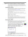
Signal Processing Products Control Program.................. 4-17
Installing the SPPCP.............................................................. 4-17
Running the SPPCP............................................................... 4-17
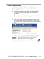
Firmware Upgrades................................................................. 4-19
Appendix A • Reference Information .............................A-1
Specifications...............................................................................A-2
Included Parts..............................................................................A-5
Accessories. ..................................................................................A-5
All trademarks mentioned in this manual are the properties of their respective owners.
68-1407-01
Rev. A
03 09
ii
RGB-DVI 300 and RGB-HDMI 300 • Table of Contents
RGB-DVI 300 and RGB-HDMI 300
1
Chapter One
Introduction
About this Manual
RGB-DVI 300 and RGB-HDMI 300 Description
RGB-DVI 300 and RGB-HDMI 300 Features
Introduction
About this Manual
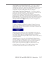
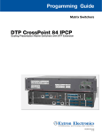
This manual contains information about the Extron RGB-DVI 300 and RGB-HDMI 300 video scalers/converters
with instructions on how to install, configure, and operate the
equipment.
Unless otherwise specified, references in this manual to the
"video converter" or "video scaler" relate to the features or
operation of both models.
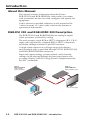
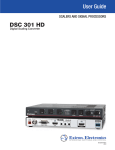
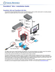
RGB-DVI 300 and RGB-HDMI 300 Description
The RGB-DVI 300 and RGB-HDMI 300 are analog to digital
video converters with built-in scaling.
The units accept a single RGB or HDTV component (R-Y, Y, B-Y)
input video signal at any standard RGB or HDTV component
resolution, through a female 15-pin HD connector.
A single video output at any of large range of resolutions
and/or refresh rates is provided through a DVI-I (RGB-DVI 300)
or HDMI (RGB-HDMI 300) connector.
Input and output settings, picture controls, and advanced
settings can be adjusted through the front panel menu with
on‑screen display, or RS-232, using Extron's Simple Instruction
Set (SIS™) commands.
Extron
MVX 128 VGA A
VGA & Audio
Matrix Switcher
Extron
RGB-HDMI 300
RGB to HDMI Scaler
T
7
SE
RE
232
RS-
LAN
7
S
UT
8
PUT
I OUT
HDM
8
REMOTE
5
6
RS232/RS422
TP
OU
3
Tx
Rx
8
7
4
1
S
UT
TP
OU
2
6
5
4
RGB
T
INPU
B
RG
MI
- HD
300
3
11
2
1
12
9
S
ER
POW
12V MAX
0.5A
12
UT
INP
11
10
7
10
9
8
5
8
S
UT
6
3
INP
7
6
4
1
5
4
3
2
D
2
LISTE
1T23
U SI.T.E.
C
1
Flat Panel Display
PC
1-2
RGB-DVI 300 and RGB-HDMI 300 • Introduction
RGB-DVI 300 and RGB-HDMI 300 Features
Accept all standard RGB and HDTV YUV inputs — through a female
15-pin HD connector.
Multiple output resolutions — These units can output an extensive
range of unique DVI (or HDMI) combinations of resolution/
refresh rate. Resolutions range from 640x480 to 1920x1200,
including 1080p, with refresh rates ranging from 23.98 to 75 Hz.
Auto Image™ — This feature automatically optimizes the image to the
scaled output rate, eliminating complex setup.
Simple Instruction Set commands — RS-232 ports on the front and
back panels allow easy configuration by a host device, using
Extron SIS commands.
Complete picture control adjustment — Input and output video
signals can be fully adjusted through the front panel menu or
through serial SIS commands.
Front panel menu selection — The front panel buttons can be used to
navigate and select menu options with the on-screen display.
Preset values — 16 Input Presets and 3 User Presets make it easy to
save and recall commonly used input sources.
Front panel security lockout — This feature locks all front panel
controls to prevent accidental or unauthorized reconfiguration.
Easy mounting — The 1" H x 8.75" W x 6" D (2.6 cm H x
22.2 cm W x 15.2 cm D) size of the units allows a wide range of
mounting options.
RGB-DVI 300 and RGB-HDMI 300 • Introduction
1-3
Introduction, cont’d
1-4
RGB-DVI 300 and RGB-HDMI 300 • Introduction
RGB-DVI 300 and RGB-HDMI 300
2
Chapter Two
Installation
Mounting the Scalers
Front Panel Layout
Rear Panel Layout
Installation
Mounting the Scalers
The 1" height and half rack width of the RGB-DVI 300 and
RGB-HDMI 300 units allow them to be mounted on a tabletop,
on racks, under furniture, or through furniture.
Tabletop placement
Attach the four provided rubber feet to the bottom of the unit
and place it in any convenient location.
Rack Mounting
UL guidelines for rack mounting
The following Underwriters Laboratories (UL) guidelines are
relevant to the safe installation of these products in a rack:
2-2
1.
Elevated operating ambient temperature — If the unit
is installed in a closed or multi-unit rack assembly, the
operating ambient temperature of the rack environment
may be greater than room ambient temperature. Therefore,
install the equipment in an environment compatible with
the maximum ambient temperature (Tma: +122 °F, +50 °C)
specified by Extron.
2.
Reduced air flow — Install the equipment in the rack
so that the equipment gets adequate air flow for safe
operation.
3.
Mechanical loading — Mount the equipment in the rack
so that uneven mechanical loading does not create a
hazardous condition.
4.
Circuit overloading — Connect the equipment to
the supply circuit and consider the effect that circuit
overloading might have on overcurrent protection
and supply wiring. Appropriate consideration of the
equipment nameplate ratings should be used when
addressing this concern.
5.
Reliable earthing (grounding) — Maintain reliable
grounding of rack-mounted equipment. Pay particular
attention to supply connections other than direct
connections to the branch circuit (such as the use of power
strips).
RGB-DVI 300 and RGB-HDMI 300 • Installation
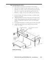
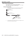
Rack mounting procedure
The unit can be mounted on any of these rack systems:
•
RSU 129: 9.5" deep, 1U rack shelf kit (part # 60-190-01)
•
RSB 129: 9.5" deep, 1U basic rack shelf (part # 60-604-01)
•
RSU 126: 6" deep, 1U rack shelf kit (part # 60-190-10)
•
RSB 126: 6" deep, 1U basic rack shelf (part # 60-604-10)
1.
Remove rubber feet if these have been installed on the
bottom of the unit.
2.
Align the holes in the base of the unit with holes in the
shelf. Secure the unit to the shelf with two 4-40 x 3/16"
screws in diagonally opposite corners (see the figure
below).
3.
Install false faceplate(s) or other unit(s) on the rack shelf.
4.
Attach the shelf to the rack with the four provided
10-32 x 3/4" bolts
6" Deep Rack Shelf
1/2 Rack Width Front False
Faceplate
Front false
faceplate
uses 2
screws.
(2) 4-40 x 3/16"
Screws
Use 2 mounting holes on
opposite corners.
Rack mounting
RGB-DVI 300 and RGB-HDMI 300 • Installation
2-3
Installation, cont’d
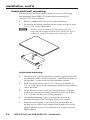
Under-desk/wall mounting
Mount the unit under a desk or podium or to a wall, using
the optional Extron MBU 125 under-desk mounting kit
(part # 70‑077‑01) as follows:
1.
Remove rubber feet if these have been attached.
2.
Secure the mounting brackets to the scaler, using the four
4-40 x 3/16" screws provided.
N
Because of the position of the mounting holes, the
units must be mounted upside-down under the desk or
podium, or with the bottom surface facing the wall.
Under-desk mounting
2-4
3.
Hold the unit, with the brackets attached, against the wall
or under the table or other furniture. Mark the location of
the bracket s' screw holes on the mounting surface.
4.
Drill four pilot holes, each 3/32" (2 mm) in diameter by
1/4" (6.3 mm) deep in the mounting surface at the marked
screw locations.
5.
Insert #8 wood screws into the four pilot holes. Tighten
each screw into the mounting surface until just less than
1/4" (6.3 mm) of the screw head protrudes.
6.
Guide the mounting screws through the slots in the
brackets and place the unit tight against the surface.
7.
Slide the unit slightly in or out so that the brackets are
resting on the screws and support the weight of the unit;
tighten all four screws to secure the unit in place (see the
figure above).
RGB-DVI 300 and RGB-HDMI 300 • Installation
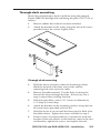
Through-desk mounting
Mount the unit through a desk or podium using the optional
Extron MBD 129 through desk mounting kit (part # 70-077-02) as
follows:
1.
Remove rubber feet if these have been attached.
2.
Attach the brackets to the scaler, using the four 4-40 screws
provided; leave the screws slightly loose.
Through-desk mounting
3.
Hold the unit in position, under the mounting surface.
Mark the location of the four screw holes and the
mounting hole to be cut in the table.
4.
Remove the table material. Test the fit by inserting the
front of the device through the hole. If necessary, use a
rasp or coarse file to enlarge the hole.
5.
Drill four pilot holes, each 3/32" (2 mm) in diameter by
1/4" deep (6.3 mm) deep.
6.
Attach the brackets to the mounting surface, using the four
#8 wood screws provided with the kit.
7.
Slide the device in or out until the front panel is flush with
the table surface. Tighten the screws installed in step 2.
8.
If these screws are inaccessible to a screwdriver, mark the
location of the unit relative to the brackets, remove the unit
and brackets, tighten the screws, and replace the unit.
RGB-DVI 300 and RGB-HDMI 300 • Installation
2-5
Installation, cont’d
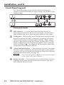
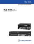
Front Panel Layout
The illustration below shows the front panel features and
controls of the RGB-HDMI 300 (upper image) and RGB-DVI 300
(lower image):
ADJUST
CONFIG
MENU
1
2
ENTER
RGB - HDMI 300
4
3
ADJUST
CONFIG
MENU
ENTER
RGB - DVI 300
Front panel layout
a
b
c
LED indicator — A solid green light indicates the unit is
receiving power and has an active video input. A solid amber
light indicates the unit is receiving power but no video input.
Config port — Both models can be configured using the Extron
Simple Instruction Set (SIS™) commands or through the Signal
Processing Products Control Program (SPPCP). Either type of
control is provided through this 2.5 mm Tip Ring Sleeve (TRS)
serial configuration port or the RS-232 captive screw connector
on the rear panel ( 8 ). See chapter 4 for instructions about SIS
commands and the control software.
Menu and Enter buttons — These buttons are used to navigate
the menu when configuring the input and output video signals
(see page 3-8) and to enable and disable the Front Panel Security
Lockout (Executive mode; see page 3-8).
N
d
2-6
To see menu selections, a display device must be attached
to the output of the video converter.
Rotary encoders — The horizontal and vertical rotary encoders
highlight menu items and adjust the value of items that have
been selected from the menu.
RGB-DVI 300 and RGB-HDMI 300 • Installation
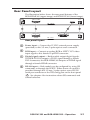
Rear Panel Layout
The illustration below shows the rear panel features of the
RGB-HDMI 300 (upper image) and RGB-DVI 300 (lower image):
POWER
12V
1.0A MAX
RGB/ R-Y, Y, B-Y INPUT
RS-232
HDMI OUTPUT
RGB - HDMI 300
5
POWER
12V
1.0A MAX
7
6
Tx Rx
8
DVI-D OUTPUT
RGB/ R-Y, Y, B-Y INPUT
RS-232
RGB - DVI 300
Tx Rx
Rear panel layout
e
f
g
h
Power input — Connect the 12 VDC external power supply
(provided) to this 3.5 mm, 2-pole captive screw connector.
RGB input — Connect an analog RGB or HDTV YUV video
input signal to this female 15-pin HD connector.
Digital signal output — Both models output digital signals.
The RGB-DVI 300 outputs a DVI-D signal through a female
DVI-I connector; the RGB-HDMI 300 outputs an HDMI signal
through a female HDMI connector.
RS-232 input — Both models can be configured by using SIS
commands or through the SPPCP. Either means of control is
provided through this 3.5 mm, 3-pole captive screw RS-232
serial port connector or the TRS config port on the front panel
( 2 ). See chapter 4 for instructions about SIS commands and
control software.
RGB-DVI 300 and RGB-HDMI 300 • Operation
2-7
Installation, cont’d
2-8
RGB-DVI 300 and RGB-HDMI 300 • Installation
RGB-DVI 300 and RGB-HDMI 300
3
Chapter Three
Operation
Input and Output Configuration
Front Panel Connections and Controls
Rear Panel Connections
Operation
Input and Output Configuration
The on-screen display menu and the serial ports can be used
to configure the unit's input and output signals. "Front panel
menu controls" later in this chapter has instructions on using the
front panel menu. Chapter 4 has instructions for SIS commands
to the unit.
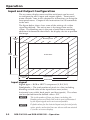
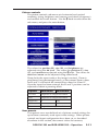
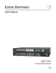
The figure below shows how some of the settings of a video
signal are defined. The active area is the image seen on the
screen. The blanking area is the part of each frame containing
additional information that allows the display device to position
the image.
Vertical
Start
Blanking Area
Total
Lines Active
Lines
Active Area
Horizontal
Start
Active Pixels
Total Pixels
Input signal
Signal type — RGB or HDTV component (Y, R-Y, B-Y)
Total pixels — The total number of pixels in a line, including
blanking on both sides of the input active area (active,
horizontal sync width, back porch, and front porch). The values
can be adjusted from the default value ± 512.
3-2
N
The total number of lines per frame, including the
blanking above and below the active area is determined
by the input signal and is not user adjustable.
N
Default values for the detected input rate for total pixels,
active pixels, and active lines are shown with an asterisk
(*) in the on-screen display.
RGB-DVI 300 and RGB-HDMI 300 • Operation
Start — The horizontal start defines the number of pixels in
the blanking area to the left of the active area; the vertical start
defines the number of pixels above the active area.
N
The vertical and horizontal starts and the active area
must be set to frame the active area of the input signal.
If these values are set incorrectly, the scaler may crop
trailing edges (right or bottom) or partially mask the
leading edges (left or top).
Active pixels — The number of pixels per line that are inside
the active area. The baseline for the active pixels adjustment
depends on the horizontal and vertical resolutions of the input
signal. The values can be adjusted from the default value ± 512.
N
The horizontal active pixels and total pixels adjustments
are interactive. Setting one of these variables may
require the other to be adjusted.
Active lines — The number of horizontal lines inside the active
area. The baseline for the active lines adjustment depends on
the input and output resolutions. The values can be adjusted
from the default value ± 256.
Phase — The timing of the digital scaler’s sampling. Sampling
at the optimum pixel phase results in a bright, stable output.
N
Total pixels and active pixels must be correctly set before
adjusting phase.
Output Signal
Auto Image — Automatically sizes and centers the input signal
to fill the screen of the output device. Auto Image can be used
to configure each input rate separately, or it can be enabled, in
the advanced menu, to automatically size and center each new
input rate.
Picture position — Sets the horizontal and vertical centers for
the output image.
Picture size — Sets the size of the output image so that it can fill
the entire display device.
Detail filter — Uses variable filters to increase or decrease the
detail and definition of the displayed image. The value can be
adjusted on a scale from 0 to 127. The default setting is 64.
Brightness — Brightness adjusts the black level of the image on
the screen, on a scale from 0 to 127. The default setting is 64.
Contrast — Contrast adjusts the difference between the input's
darkest and brightest settings, on a scale from 0 to 127 (the
default is 64).
RGB-DVI 300 and RGB-HDMI 300 • Operation
3-3
3-4
X
X
X
X
X
X
X
X
X
X
X
X
X
1024 x 768
1024 x 852
1024 x 1024
1280 x 768
1280 x 800
1280 x 1024
1360 x 765
1360 x 768
1365 x 768
1366 x 768
1365 x 1024
1440 x 900
1400 x 1050
50
X
30
852 x 480
29.97
X
25
800 x 600
24
X
23.98
Refresh Rate (Hz)
640 x 480
Resolution
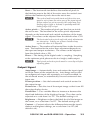
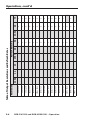
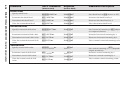
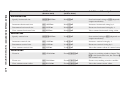
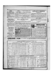
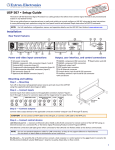
Table of Output Resolutions and Refresh Rates
59.94
RGB-DVI 300 and RGB-HDMI 300 • Operation
X
X
X
X
X
X
X
X
X
X
X
X
X
X
X
X
60
X
X
X
X
X
X
X
X
X
X
X
X
X
X
75
Operation, cont’d
RGB-DVI 300 and RGB-HDMI 300 • Operation
3-5
X
X
Output rate will match input resolution and refresh rate
X
LOCK
X
Output resolution based on display EDID
X
AUTO
X
X
2048 x 1080
X
X
X
X
1080p
X
X
1080i
X
X
720p
X
X
576p
480p
X
50
X
30
1920 x 1200
29.97
X
25
1600 x 1200
24
X
23.98
Refresh Rate (Hz)
1680 x 1050
Resolution
X
X
X
X
X
59.94
60
X
X
X
X
X
X
X
X
75
Operation, cont’d
Zoom — Zoom enlarges a portion of the scaled image.
N
Zoom values match picture size values.
Output Resolution and refresh rate — Every display device has
an optimal (native) resolution and refresh rate. It is essential
that the output resolution and refresh rate match the display
device's capabilities. The table on the two previous pages
shows the full range of resolutions and refresh rates available
for output signals with these scalers. There are two additional
settings:
•
When Auto is selected, the video converter receives EDID
information from the display device and adjusts the output
signal to match the requirements of the display
•
When Lock is selected, the video converter matches the
resolution and refresh rate of the output signal with those of
the input signal.
Other
User presets — When contrast, brightness, detail, horizontal
and vertical centering, and horizontal and vertical size have
been adjusted, the values can be saved as presets. This allows
the values for the three most commonly used picture control
settings to be instantly recalled, which is useful for handling
inputs with different aspect ratios.
Test pattern — Test patterns help in the configuration of the
output signal. The available patterns include Color Bars,
grayscale, cross-hatch, alternating pixels, crop, 1.33 aspect ratio,
1.78 aspect ratio, 1.85 aspect ratio, 2.35 aspect ratio, and off (no
test pattern).
Freeze — When freeze is enabled, the video output is a still
image of the last active frame. The output will remain frozen
even if the input signal is removed.
Blank — When blank is enabled, no video signal is sent to the
output device, although the on‑screen display is still available.
Reset — There are two types of reset. Firmware reset returns all
options, including the firmware to the factory defaults. Factory
reset returns all image options to the factory defaults but keeps
the current version of the firmware. For more information, see
page 3-17.
3-6
RGB-DVI 300 and RGB-HDMI 300 • Operation
Front Panel Connections and Controls
The front panels of both the RGB-DVI 300 and the
RGB-HDMI 300 have a green/amber LED indicator, a config
port, menu and enter buttons, and two rotary encoders (see
page 2-6).
LED indicator
A green light indicates the unit is receiving power and has an
active video input. An amber light indicates the unit is receiving
power but no video input.
Config port
Both the video scaler/converters accept SIS commands from
a host device such as a computer running the HyperTerminal
utility or other control system.
To connect the host device to the config port on the front
panel, use the optional Extron 9-pin D female to 2.5 mm TRS
Configuration Cable (PN 70-335-01). The same port can also be
used to provide control by the SPPCP. For more information
about SIS and the control software, see chapter 4.
1
6
5
Tip
Ring
Sleeve (Gnd)
9
Male DB9 Connector
2.5 mm TRS Connector
Pin Configuration
Male
Pin
2
3
5
TRS
Tip
Ring
Sleeve
RS-232
Function
Transmit (Tx)
Receive (Rx)
Ground ( )
Control commands can also be sent through the 3-pin captive
screw connector on the rear panel (see page 3-20).
N
Only one serial port can be used at a time. If the front
port is in use, the rear captive screw connector must be
disconnected from the computer or other control device.
Likewise, if the captive screw port is in use, the Config
port on the front panel must be disconnected from the
computer or other control device.
RGB-DVI 300 and RGB-HDMI 300 • Operation
3-7
Operation, cont’d
Front panel menu controls
The menu and enter buttons and rotary encoders are used to
configure and optimize the unit's input and output signals.
N
The menus for the RGB-DVI 300 and RGB-HDMI 300
are On-Screen Dipslay (OSD). To see menu selections, a
display device must be attached to the output of the video
scaler/converter.
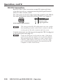
Front panel security lockout (executive mode)
When the front panel security lockout, also known as executive
mode, is enabled, all front panel controls are locked. RS-232
control remains available.
Front panel security lockout is enabled by pressing and holding
the menu and enter buttons simultaneously for two seconds.
It can also be enabled using an SIS command (see page 4-14).
When front panel security lockout has been enabled, the
following message will appear on‑screen for approximately two
seconds:
This message also displays if the user attempts to use any of the
front panel controls while the executive mode is enabled.
Front panel security lockout is disabled by pressing and holding
the menu and enter buttons simultaneously for two seconds. It
can also be disabled by sending the appropriate SIS command
(see page 4-15). When front panel security lockout has been
disabled, the following message will appear on‑screen for
approximately two seconds:
When front panel security lockout is disabled, the unit can be
fully configured from the front panel without restrictions.
Main menu
The menu and enter buttons and the two rotary encoders are
used to enter and navigate the menu, which is displayed on the
output screen.
ADJUST
MENU
3-8
ENTER
RGB-DVI 300 and RGB-HDMI 300 • Operation
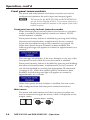
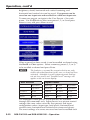
Press the Menu button to open the menu. A header that
identifies the model and the top-level menu appears on the
output display.
N
In all following figures the RGB-DVI 300 has been used
in the illustrations. Apart from the heading, the
RGB-HDMI 300 menu is identical in all respects.
The six options of the top-level menu are Auto-Image,
Picture Controls, User Presets, Input Configuration, Output
Configuration, and Advanced Configuration.
The option that is currently highlighted appears as white text
in a light blue box, with a white border. The other options and
the header are shown as white text in a dark blue box. Turn the
{ rotary encoder to move between menu items and highlight the
desired option.
Press the Enter to select the highlighted button and move deeper
into the menu. Press the Menu button to return to a higher level
of the menu system. When a sub-menu item is highlighted, it
appears as a light blue box with white text and a white border.
To select that item, press the Enter button again. The selected
item will appear as a gray box with white text and a white
border.
RGB-DVI 300 and RGB-HDMI 300 • Operation
3-9
Operation, cont’d
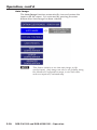
Auto Image
The Auto Image function automatically sizes and centers the
input to fill the screen. It is activated by pressing the enter
button after Auto Image has been selected.
N
3-10
This feature initiates a one-time auto image on the
current input. Auto image can also be set globally, using
the Advanced Configuration menu, to size and center
each new input rate, automatically.
RGB-DVI 300 and RGB-HDMI 300 • Operation
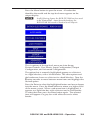
Picture controls
The picture controls sub-menu sets horizontal and vertical
centering, sizing, brightness and contrast, and detail (sharpness)
and controls the zoom feature. Use the { knob to select from the
sub-menu, and press the enter button.
The values for position (H), size (H), and brightness are
adjusted using the [ knob. The values for position (V), size
(V), and contrast are adjusted using the { knob. The values for
detail and zoom can be adjusted using either knob.
Zoom locks the aspect ratio as the image is resized. Zoom is
pixel based (not percentage based), so the current Zoom values
for H and V will match the current Size values for H and V.
Once the input has been zoomed, the H and V positions can be
adjusted to obtain a panning effect.
Option
Minimum
Maximum
Position
Depends on output resolution
Size
Depends on output resolution
Brightness
0
127
Contrast
0
127
Zoom
Depends on output resolution
User presets
User presets are a user defined set of picture control settings for
up to three commonly used aspect ratio settings. When picture
controls and input configuration have been set, as described
elsewhere in this section, the current values for contrast,
RGB-DVI 300 and RGB-HDMI 300 • Operation
3-11
Operation, cont’d
brightness, detail, horizontal and vertical centering, and
horizontal and vertical size can be saved. User presets can be
saved on one input rate and recalled for a different input rate.
To save user presets, navigate to the User Presets > Save submenu. Use the { knob to select user preset 1, 2, or 3 and press
Enter to save, and press Menu to exit.
When a preset has been saved, it can be recalled or cleared using
the Recall or Clear options. Select a memory preset (1, 2, or 3)
to be recalled or cleared and press Enter.
N
The brackets <> around the current selection are only
visible when that function (recall, save, or clear) has been
activated. Attempts to recall a memory preset that has
not yet been saved, and "Invalid Preset" message will
appear on the on-screen display.
User Presets
Input Presets
H position
Input type
H start
H position
V position
Total Pixel
V start
V position
Contrast
H size
Contrast
H active
H size
Brightness
V size
Brightness
V active
V size
Detail
Zoom
Detail
Phase
Zoom
An additional sixteen presets (input presets) are available
through SIS commands only. Input presets save picture control
settings (the same values saved by user presets) and input
configuration values (input type, total pixels, horizontal and
vertical starts, horizontal and vertical active areas and phase).
The exact settings of a source are saved and can be recalled each
3-12
RGB-DVI 300 and RGB-HDMI 300 • Operation
time that source is used. Input presets are only valid for the
source/resolution that was active when the preset was saved.
Input configuration
The input configuration submenu is used to adjust input type,
total pixels, phase, horizontal and vertical video start, and
horizontal and vertical active areas.
N
On the on-screen menu display, default values for the
current input rates, total pixels, H active, and V active
are accompanied by an asterisk (*).
With the start or active options, use the [ knob to adjust the
horizontal values and the { knob to adjust the vertical values.
Total pix and phase are adjusted by the [ and { knobs,
respectively.
Option
Minimum
Input
RGB (default) or YUV
Maximum
Total Pix
default value (depends on input resolution) ± 512
Phase
0
31
Horizontal start
Vertical start
0
255
0
255
Active Pixels
default value (depends on input resolution) ± 512
Active Lines
default value (depends on input resolution) ± 256
RGB-DVI 300 and RGB-HDMI 300 • Operation
3-13
Operation, cont’d
Output configuration
The output configuration is used to select a scaler output rate
from the various available resolution and refresh rates. Both
the RGB-DVI 300 and the RGB-HDMI 300 have a large range of
combinations of resolution and refresh rate (see table on pages
3-4 and 3-5).
Select output configuration from the main menu. Use the
[ knob to select a resolution. Then use the { knob to select a
refresh rate. Apply the settings by pressing the enter button, or
they will be applied automatically after 5 seconds.
In addition to the resolutions and refresh rates available in the
menu, two other options are available:
Auto — The unit receives EDID information from the display
device and adjusts the output signal to match the requirements
of the display.
Lock — The unit matches the resolution and refresh rate of the
output signal with those of the input signal.
When color space is selected, the two available options are RGB
(default) and YUV. Use the up/down rotary encoder to select
the desired value and then apply the setting by pressing the
enter button.
3-14
RGB-DVI 300 and RGB-HDMI 300 • Operation
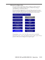
Advanced configuration
The advanced configuration menu configures global settings,
including Test Patterns, Blank, Freeze, Global Auto Image,
Auto Memory, and Factory Reset.
The advanced configuration is activated by pressing the menu
button to display the main menu, using either rotary encoder to
select advanced configuration and pressing the enter button.
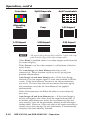
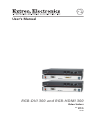
Test pattern can be set to Color Bars, grayscale, crosshatch,
alternating pixels, crop, four different aspect ratios, or off. These
patterns are used to configure the output signal.
RGB-DVI 300 and RGB-HDMI 300 • Operation
3-15
Operation, cont’d
Color Bars
Split Grayscale
4x4 Crosshatch
Alternating
Pixels
Crop
1.33 Aspect
1.78 Aspect
1.85 Aspect
2.35 Aspect
N
All aspect ratio patterns also include a 1 pixel wide crop
pattern at the edge of the video output raster.
When Blank is enabled, there is no video output (aside from the
on-screen display).
When Freeze is on, the video output is a still picture of the last
active frame.
The Auto Image and Auto Memory functions work
interactively. Either function can be on or off, giving four
possible combinations.
Auto Image on and Auto Memory on — If the Auto Image
function is on, the output signal is sized and centered to fill the
screen. If the Auto Memory function is on, these parameters
are saved. The next time the unit encounters the same signal,
the parameters saved by the Auto Memory are applied
automatically.
When all 64 memories are filled, the oldest is overwritten by
new ones.
Auto Image off and Auto Memory on — If the Auto Image is
off, the unit applies the values from the input lookup table. If
no further adjustments are made, the Auto Memory does not
save an entry, since all the parameters already match the input
lookup table. However, if the user adjusts the input manually or
carries out an Auto Image, the new parameters is automatically
stored by the Auto Memory function.
3-16
RGB-DVI 300 and RGB-HDMI 300 • Operation
Auto Image on and Auto Memory off — Each new signal is
compared with the values in the input lookup table and an
Auto Image carried out. However, the parameters are not saved
and the next time this signal is encountered, it is, once again,
compared with the lookup table and Auto Imaged.
Auto Image off and Auto Memory off — Each new signal is
set up with the default values. There is no Auto Image and the
parameters are not saved by the Auto Memory.
To reset all user settings, but keep the current version of the
firmware, enter the menu, select advanced configuration, and
Factory Reset. Press and hold the enter button until the "Factory
Reset" message is displayed on the screen. This is the same as
the Zap SIS command (EZXXX}), as shown on page 4-16.
To reset all options, including the original shipped firmware
to the factory defaults, press and hold the enter button while
applying power; the "Firmware Reset" message is displayed on
the on-screen display.
When the output display has an incompatible output rate, it
is often difficult to get an image on the display. An additional
reset mode allows the user to toggle between two almost
universally applicable output rates of 1024 x 768 at 60 Hz (XGA)
and 720p at 60 Hz.
Applying power to the unit while holding the Menu button
initially changes to output rate to 1024 x 768 at 60 Hz. On the
next occasion power is applied to the unit while holding the
Menu button, the output rate toggles to 720p at 60 Hz.
These values were chosen because most PC monitors with
a digital input will accept an XGA signal and most other
consumer/professional displays will accept 720p.
RGB-DVI 300 and RGB-HDMI 300 • Operation
3-17
Operation, cont’d
Rear Panel Connections
The rear panels of both the RGB-DVI 300 and the
RGB-HDMI 300 have a power input, RGB/HDTV YUV signal
input, digital signal output, and RS-232 port.
Power Connections
1.
POWER
12V
1.0A MAX
Connect the captive screw connector from the supplied
12 VDC power supply into the power receptacle.
Back Panel
Power Receptacle
DC Power Cord
Captive Screw Connector
Ground
+12 VDC
AC Power Cord
2.
3-18
External
Power Supply
(12 VDC, 2 A )
Connect the AC power cord of the power supply unit to a
110 or 220 VAC electrical source.
RGB-DVI 300 and RGB-HDMI 300 • Operation
Input Connections
The RGB-DVI 300 and RGB-HDMI 300 accept RGB (RGBHV,
RGBS, RGsB, and RsGsBs) and HDTV component (YUV)
signals. Connect the input signal to the 15 pin female HD
connector on the back of the scaler.
If necessary, use a BNC to VGA adapter cable, such as the Extron
SY BNCM series (PN 26-533-xx; see the figure below).
RGBHV
R
G
B
H
V
R
G
B
S
V
R
Rs
Gs
Gs
Y
B
H
V
RGBS
RGsB,
RsGsBs,
Component
R-Y
Bs
B-Y
Output Connections
Use the Female DVI-I connector (RGB-DVI 300) or the Female
HDMI connector (RGB-HDMI 300) to pass the output signal to
the display device.
DVI-D OUTPUT
Rear panel DVI connector (RGB-DVI 300)
N
Although the RGB-DVI 300 has a rear panel DVI-I
connector, the output signal is DVI-D (digital only).
HDMI OUTPUT
Rear panel HDMI connector (RGB-HDMI 300)
RGB-DVI 300 and RGB-HDMI 300 • Operation
3-19
Operation, cont’d
RS-232 Connection
Both the video scaler/converters accept SIS commands from
a host device such as a computer running the HyperTerminal
utility or other control system.
The same port can also be used to provide control by the SPPCP.
For more information about SIS and the SPPCP, see chapter 4.
RS-232
Tx Rx
3 Pin Captive Screw Connector
N
Pin
Tx
Rx
Function
Transmit data
Receive data
Signal ground
The wiring in the RS-232 cables must cross over so that
the transmit port of the control device connects with the
receive port of the video converter and vice versa.
Control commands can also be sent through the TRS Config port
on the front panel (see page 3-7).
N
3-20
Only one serial port can be used at a time. If the front
port is in use, the rear captive screw connector must be
disconnected from the computer or other control device.
Likewise, if the captive screw port is in use, the config
port on the front panel must be disconnected from the
computer or other control device.
RGB-DVI 300 and RGB-HDMI 300 • Operation
RGB-DVI 300 and RGB-HDMI 300
4
Chapter Four
Controls
Introduction to SIS™
Symbols used in this manual
Command/response table for SIS commands
Signal Processing Products Control Program
Serial Communications
Introduction to SIS™
Both the RGB-DVI 300 and the RGB-HDMI 300 accept SIS
commands from a host device such as a computer running the
HyperTerminal utility or other control system. The host device
can be connected to the 3-pin captive screw connector on the
rear panel or to the Config port on the front panel. To connect
to the config port, use the optional Extron 9-pin D female to 2.5
mm TRS Configuration cable (part # 70-335-01).
The protocol is 9600 baud, 8 data bit, 1 stop bit, and no parity.
N
The wiring in the RS-232 cables crosses over so that
the video scaler/converter Tx connects with the control
device Rx and vice versa.
N
Only one serial port can be used at a time. If the front
port is in use, the rear captive screw connector must be
disconnected from the computer or other control device.
Likewise, if the captive screw port is in use, the config
port on the front panel must be disconnected from the
computer or other control device.
SIS commands consist of a string (one or more characters per
command field). Unless otherwise stated, upper and lower
case characters may be used interchangeably. Commands do
not require any special characters to begin or end the command
string. Each response from the video converter ends with a
carriage return and a line feed (CR/LF = ]), which signals the
end of the response character string.
When the RGB-DVI 300 or RGB-HDMI 300 is first switched on,
depending on the model, it sends the message:
(c) COPYRIGHT 2009, EXTRON ELECTRONICS,
RGB‑DVI 300, V x.xx, 60-906-01] or
(c) COPYRIGHT 2009, EXTRON ELECTRONICS,
RGB‑HDMI 300, V x.xx, 60-907-01]
where V x.xx is the firmware version number and 60-90x-01 is
the part number.
4-2
RGB-DVI 300 and RGB-HDMI 300 • Serial Communications
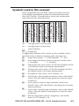
Symbols used in this manual
When programming in the field, certain characters are most
conveniently represented by their hexadecimal rather than
their ASCII values. The table below shows the hexadecimal
equivalent of each ASCII character:
ASCII to HEX Conversion Table
Space
.
] — carriage return with line feed
} — carriage return (no line feed)
• — space character
E — Escape key
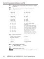
The X/ values defined in this section are the variables used in
the fields of the command response table (see page 4-6).
X! — Input video format: 1 = RGB (default) 2 = YUV
X@ — Auto image, blanking, freeze or executive mode status:
0 = disabled 1 = enabled
X# — Horizontal start value: from 0 to 255 (the midpoint of 128
is the default value in the input lookup tables)
X$ — Vertical start value: from 0 to 255 (the midpoint of 128 is
the default value in the input lookup tables)
X% — Pixel phase value: from 1 to 31 (default = 16)
X^ — Total pixels value for high resolution video is the default
value ± 512 (the default value depends on the the input
resolution)
X& — Active pixels value for high resolution video is the
default value ± 512 (the default value depends on the the
input resolution)
X* — Active lines value for high resolution video is the default
value ± 256 (the default value depends on the the input
resolution)
X1) — Picture adjustment (contrast, brightness, and detail):
from 0 to 127 (default = 64)
RGB-DVI 300 and RGB-HDMI 300 • Serial Communications
4-3
Serial Communications, cont’d
X1! — Horizontal and vertical shift values (depend on output
resolution)
X1@ — Horizontal and vertical size (depend on output)
X1% — Output resolutions:
1 = 640 x 480
17 = 1680 x 1050
2 = 800 x 600
18 = 1600 x 1200
3 = 852 x 480
19 = 1920 x 1200
4 = 1024 x 768 (default)
20 = 480p
5 = 1024 x 852
21 = 576p
6 = 1024 x 1024
22 = 720p
7 = 1280 x 768
23 = 1080i
8 = 1280 x 800
24 = 1080p
9 = 1280 x 1024
25 = 2048 x 1080
10 = 1360 x 765
30 = AUTO (display EDID
controlled).
Not valid for EDID emulation.
31 = LOCK (output rate locked
to input resolution and refresh).
Not valid for EDID emulation.
32 = OUTPUT RATE (VGA
EDID emulation matches
current ouput rate — valid for
VGA EDID emulation only; not
valid for output rate setting.)
11 = 1360 x 768
12 = 1365 x 768
13 = 1366 x 768
14 = 1365 x 1024
15 = 1440 x 900
16 = 1400 x 1050
X1^ — Output refresh rates:
0 = Auto, Lock, or "Output
Rate" EDID emulation
5 = 30 Hz
1 = 23.98 Hz
6 = 50 Hz
2 = 24 Hz
7 = 59.94 Hz
3 = 25 Hz
8 = 60 Hz (default)
4 = 29.97 Hz
9 = 75 Hz
X1& — Ouput format (color space)
0 = RGB (default) 1 = YUV
X1* — User presets: from 1 to 3
X1( — Input presets: from 1 to 16
N
4-4
Input presets are available only through SIS commands.
RGB-DVI 300 and RGB-HDMI 300 • Serial Communications
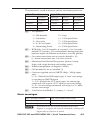
The parameters saved in memory presets and input presets are:
User Presets
Input Presets
H position
Input type
H start
H position
V position
Total Pixel
V start
V position
Contrast
H size
Contrast
H active
H size
Brightness
V size
Brightness
V active
V size
Detail
Zoom
Detail
Phase
Zoom
X2) — Test patterns:
0 = Off (default)
5 = Crop
1 = Color Bars
6 = 1.33 Aspect Ratio
2 = Grayscale
7 = 1.78 Aspect Ratio
3 = 4 x 4 Crosshatch
8 = 1.85 Aspect Ratio
4 = Alternating Pixels
9 = 2.35 Aspect Ratio
X2! — RGB delay (0 to 50 in tenths of a second – 0 to 5 seconds;
default 0.5 seconds). The screen blanks during transition
between inputs of different resolutions, to avoid glitches.
X2@ — On‑screen menu time out in seconds (default = 10)
0 = menu never times out; 1 to 64 in seconds
X2# — Horizontal and Vertical Frequencies (format is three
digits with single decimal and leading zeros).
X2$ — Internal temperature (in degrees Celsius)
X2% — Off/disabled (0) or on/enabled (1)
X2^ — Overscan: applied only to SMPTE (480p - 1080p) input
rates.
0 = 0% (Default for RGB input type) A "true" auto image
is executed on SMPTE inputs
1 = 2.5% (Default for YUV input type) An auto image
command will snap to a 2.5% table; no true auto image
2 = 5% An auto image command will snap to a 5% table;
no true auto image
X2& — User Preset Availability: 0 = empty; 1 = saved
Error messages
E10 = Invalid command
E14 = Not valid for this config.
E11 = Invalid preset number
E17 = Invalid command for signal type
E13 = Invalid parameter
E22 = Busy
N
If the RGB-DVI 300 or RGB-HDMI 300 does not
support or recognize the entered commands, nothing will
happen and no response is issued.
RGB-DVI 300 and RGB-HDMI 300 • Serial Communications
4-5
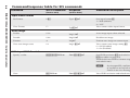
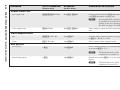
Command
RGB-DVI 300 and RGB-HDMI 300 • Serial Communications
ASCII Command
Response
Additional Description
Set Format
1*X!\
Typ1* X!]
Sets input format X!.
1 = RGB (default)
2 = YUV
View Format
1\
TypX!]
View current video input format.
Enable
1*1A
Img1*1]
Auto image input when selected.
Disable
1*0A
Img1*0]
Disable auto image.
Execute
A
Img]
Execute auto image on current input.
View auto image status
1A
Img1* X@]
View current auto image setting X@.
0 = Off (Disabled)
1 = On (Enabled)
EX1%*X1^EDID}
Edid X1%*X1^]
Sets EDID resolution X1% and refresh rate
X1^ (see tables on page 4-4).
(Default 32*0 sets EDID to current output
and refresh rates).
(host to unit)
(unit to host)
Input video format
Auto image
VGA input EDID Emulation
Specify a value
N
View
EEDID}
Edid X1%*X1^]
An incompatible combination
of resolution and refresh rate
results in an error message.
View EDID resolution and refresh rate.
Serial Communications, cont’d
4-6
Command/response table for SIS commands
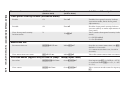
Command
RGB-DVI 300 and RGB-HDMI 300 • Serial Communications
ASCII Command
Response
Additional Description
Set a horizontal start value
EX#HSRT}
HsrtX#]
Set the horizontal location of the first active
pixel X# (from 0 to 255) for active input.
Increment horizontal start value
E+HSRT}
HsrtX#]
Increases the horizontal start value by 1.
Decrement horizontal start value
E-HSRT}
HsrtX#]
Decreases the horizontal start value by 1.
View horizontal start value
EHSRT}
HsrtX#]
View the horizontal location of the first
active pixel.
Set a vertical start value
EX$VSRT}
VsrtX$]
Set the vertical location of the first active
pixel X$ (from 0 to 255) for active input.
Increment vertical start value
E+VSRT}
VsrtX$]
Increases the vertical start value by 1.
Decrement vertical start value
E-VSRT}
VsrtX$]
Decreases the vertical start value by 1.
View vertical start value
EVSRT}
VsrtX$]
View the vertical location of the first active
pixel.
Specify a value
EX%PHAS}
PhasX%]
Adjust pixel phase to specified value X%
(from 1 to 31) for active input.
(host to unit)
(unit to host)
Horizontal start
Vertical start
Pixel phase
4-7
Increment pixel phase value
E+PHAS}
PhasX%]
Increases pixel phase value by 1.
Decrement pixel phase value
E-PHAS}
PhasX%]
Decreases pixel phase value by 1.
View pixel phase value
EPHAS}
PhasX%]
View the pixel phase value.
RGB-DVI 300 and RGB-HDMI 300 • Serial Communications
ASCII Command
Response
Additional Description
Specify a value
EX^TPIX}
TpixX^]
Adjust total number of pixels to specified
value for active input.
X^ Total pixels = default value ± 512
Increment total number of pixels
E+TPIX}
TpixX^]
Increases total number of pixels by 1.
Decrement total number of
pixels
E-TPIX}
TpixX^]
Decreases total number of pixels by 1.
View total number of pixels
ETPIX}
TpixX^]
View total number of pixels.
Specify a value
EX&APIX}
ApixX&]
Adjust number of pixels to specified value
for active input.
X& Active pixels = default value ± 512
Increment number of active
pixels
E+APIX}
ApixX&]
Increases number of active pixels by 1.
Decrement number of active
pixels
E-APIX}
ApixX&]
Decreases number of active pixels by 1.
View number of active pixels
EAPIX}
ApixX&]
View number of active pixels.
Specify a value
EX*ALIN}
AlinX*]
Adjust number of active lines to specified
value for active input.
X* Active lines = default value ± 256
Increment number of active lines
E+ALIN}
AlinX*]
Increases number of active lines by 1.
(host to unit)
(unit to host)
Total pixels
Active pixels
Active lines
Serial Communications, cont’d
4-8
Command
Command
RGB-DVI 300 and RGB-HDMI 300 • Serial Communications
ASCII Command
Response
Additional Description
Decrement number of active
lines
E-ALIN}
AlinX*]
Decreases number of active lines by 1.
View number of active lines
EALIN}
AlinX*]
View number of active lines.
Enable mute
1B
Vmt1]
Blanks selected input.
Disable mute
0B
Vmt0]
Displays selected input.
View mute status
B
VmtX@]
View blanking status X@.
0 = Off (Disabled)
1 = On (Enabled)
(host to unit)
(unit to host)
Video mute
Contrast
4-9
Specify contrast level
EX1)CONT}
ContX1)]
Sets contrast level to X1) (from 0 to 127).
Increment the contrast level
E+CONT}
ContX1)]
Increases the contrast value by 1.
Decrement the contrast level
E-CONT}
ContX1)]
Decreases the contrast value by 1.
View the current contrast level
ECONT}
ContX1)]
View the current contrast value.
Specify brightness level
EX1)BRIT}
BritX1)]
Sets brightness level to X1) (from 0 to 127)
Increment the brightness level
E+BRIT}
BritX1)]
Increases the brightness value by 1.
Decrement the brightness level
E-BRIT}
BritX1)]
Decreases the brightness value by 1.
View the current brightness level
EBRIT}
BritX1)]
View the current brightness value.
Brightness
ASCII Command
Response
Additional Description
(host to unit)
(unit to host)
RGB-DVI 300 and RGB-HDMI 300 • Serial Communications
Detail filter
Specify detail level
EX1) HDET}
HdetX1)]
Sets detail level to X1) (from 0 to 127).
Increment the detail level
E+HDET}
HdetX1)]
Increases the detail level by 1.
Decrement the detail level
E-HDET}
HdetX1)]
Decreases the detail level by 1.
View the current detail level
EHDET}
HdetX1)]
View the current detail level.
Specify horizontal shift value
EX1!HCTR}
HctrX1!]
Sets horizontal centering to X1! (depends
on output resolution).
Increment horizontal shift value
E+HCTR}
HctrX1!]
Increases horizontal centering by 1.
Decrement horizontal shift value
E-HCTR}
HctrX1!]
Decreases horizontal centering by 1.
View the current horizontal shift
value
EHCTR}
HctrX1!]
View current horizontal centering value.
Specify vertical shift value
EX1!VCTR}
VctrX1!]
Sets vertical centering to X1! (depends on
output resolution).
Increment vertical shift value
E+VCTR}
VctrX1!]
Increases vertical centering by 1.
Decrement vertical shift value
E-VCTR}
VctrX1!]
Decreases vertical centering by 1.
View the current vertical shift
value
EVCTR}
VctrX1!]
View current vertical centering value.
Horizontal shift
Vertical shift
Serial Communications, cont’d
4-10
Command
Command
RGB-DVI 300 and RGB-HDMI 300 • Serial Communications
ASCII Command
Response
Additional Description
Specify horizontal size
EX1@HSIZ}
HsizX1@]
Sets horizontal sizing to X1@ (depends on
output resolution).
Increment horizontal size
E+HSIZ}
HsizX1@]
Increases horizontal sizing by 1.
Decrement horizontal size
E-HSIZ}
HsizX1@]
Decreases horizontal sizing by 1.
View current horizontal size
EHSIZ}
HsizX1@]
View current horizontal sizing value.
Specify vertical size
EX1@VSIZ}
VsizX1@]
Sets vertical sizing to X1@ (depends on
output resolution).
Increment vertical size
E+VSIZ}
VsizX1@]
Increases vertical sizing by 1.
Decrement vertical size
E-VSIZ}
VsizX1@]
Decreases vertical sizing by 1.
View current vertical size
EVSIZ}
VsizX1@]
View the current value of vertical sizing.
Zoom in
E+ZOOM}
ZoomX1@*X1@]
Zooms in, making window larger. The first
X1@ is the horizontal size, the second X1@ is
the vertical size.
Zoom out
E-ZOOM}
ZoomX1@*X1@]
Zooms out, making window smaller.
View current zoom value
EZOOM}
ZoomX1@*X1@]
View the current zoom value.
(host to unit)
(unit to host)
Horizontal size
Vertical size
Zoom mode
4-11
RGB-DVI 300 and RGB-HDMI 300 • Serial Communications
ASCII Command
Response
Additional Description
EX1%*X1^RATE}
RateX1% * X1^]
Selects scaler resolution X1% and refresh
rate X1^ (see tables on page 4-4).
(host to unit)
(unit to host)
Output scaler rate
Set output rate
N
An incompatible combination
of resolution and refresh rate
results in an error message. See
the table on pages 3-4 and 3-5.
ERATE}
RateX1% * X1^]
View current output resolution and refresh
rate.
Set
EX1& VTPO }
VtpoX1&]
Sets the video output format (color space)
to X1& (0 = RGB, 1 = YUV).
View
E VTPO }
VtpoX1&]
View current video output format.
1*X1*,
1SprX1*]
Saves current settings for selected input as
user preset X1* (1 to 3).
View output rate
Video output format
User presets
Save preset
N
Recall user preset
1*X1*.
1RprX1*]
The final character of the
command is a comma (,).
Recalls user preset X1* (1 to 3) for selected
input.
N
The final character of the
command is a period (.).
Serial Communications, cont’d
4-12
Command
Command
RGB-DVI 300 and RGB-HDMI 300 • Serial Communications
ASCII Command
Response
Additional Description
2*X1(,
2SprX1(]
Saves current settings as memory preset
X1( (1 to 16).
(host to unit)
(unit to host)
Input presets
Save preset
N
Recall preset
2*X1(.
2RprX1(]
Recalls input preset X1( (1 to 16).
N
The parameters saved in Memory Presets and Input Presets are:
Memory Presets
The final character of the
command is a comma (,).
Input Presets
H position
Input type
H start
H position
V position
Total Pixel
V start
V position
Contrast
H size
Contrast
H active
H size
Brightness
V size
Brightness
V active
V size
Detail
Zoom
Detail
Phase
Zoom
The final character of the
command is a period (.).
4-13
RGB-DVI 300 and RGB-HDMI 300 • Serial Communications
ASCII Command
Response
Additional Description
Enable
E1AMEM}
Amem1]
Sets auto memory on. Previous settings for
incoming signals are auto recalled.
Disable
E0AMEM}
Amem0]
Sets auto memory to off. Defaults to input
lookup table values to configure input.
View Auto Memory status
EAMEM}
AmemX@]
View current auto memory status X@.
0 = Off (Disabled)
1 = On (Enabled)
Set Test Pattern
EX2)TEST}
TestX2) ]
Set test pattern to X2) (see list of test
patterns on page 4-5).
View Test Pattern
ETEST}
TestX2) ]
View current test pattern status.
Enable
1F
Frz1]
Freezes input.
Disable
0F
Frz0]
Unfreezes input.
View freeze status
F
FrzX@]
Shows the current freeze status X@.
0 = Off (Disabled)
1 = On (Enabled)
Set delay time
EX2!VDLY}
VdlyX2! ]
Set RGB delay time X2! (in tenths of a
second - 0 to 5 seconds).
View delay time
EVDLY}
VdlyX2! ]
View current RGB delay setting
(host to unit)
(unit to host)
Auto memories
Test pattern
Freeze
RGB delay time
Serial Communications, cont’d
4-14
Command
Command
ASCII Command
(host to unit)
Response
Additional Description
(unit to host)
RGB-DVI 300 and RGB-HDMI 300 • Serial Communications
Front panel security lockout (executive mode)
Enable
1X
Exe1]
Enables front panel security lockout
(executive mode; limits front panel
adjustments).
Disable
0X
Exe0]
Disables front panel security lockout
(restores ability to make adjustments from
font panel).
View front panel security
lockout status
X
ExeX@]
View current front panel security lockout
status.
0 = Off (Disabled)
1 = On (Enabled)
Set menu time out
EX2@MDUR }
MdurX2@ ]
Sets the on-screen menu time out X2@
default = 10 seconds.
(0 = menu never times out; 1 to 64 in
seconds).
View menu time out status
EMDUR }
MdurX2@]
View the current menu time out status.
Menu time out
Overscan Mode (Applies only to SMPTE (480p - 1080p) input rates)
4-15
Set value
EX!*X2^OSCN}
OscnX!*X2^]
Sets input type X! (1 = RGB; 2 = YUV)
to overscan mode X2^ (0 = 0%; 1 = 2.5%;
2 = 5%).
View status
EX!OSCN}
OscnX!*X2^]
View overscan mode status for input type
X!.
RGB-DVI 300 and RGB-HDMI 300 • Serial Communications
ASCII Command
Response
Additional Description
General information
I/i
Vid 1 • Typ X! • Blk X@ •
Pre X2&X2&X2& • Hrt X2#
• Vrt X2# ]
View input type X!, mute status X@, the
availability of the three user presets X2& (0
= empty; 1 = saved), input horizontal scan
rate X2#, and input vertical scan rate X2#.
Query model name
1I
RGB-DVI 300] or
RGB-HDMI 300]
Query model description
2I
Extron Electronics Digital
Video Scaler]
Query firmware version
Q
x.xx]
View the firmware version.
Query firmware version (full)
*Q
x.xx.xxxx]
View the full firmware version.
Query part number
N
xx-xxx-xx]
View the unit part number.
(RGB-DVI 300 is 60-906-01;
RGB-HDMI 300 is 60-907-01)
View internal temperature
E20STAT}
Stat20•X2$]
View the internal temperature of the unit
(in degrees Celsius).
Reset all settings to factory
EzXXX}
Zpx]
Resets all user device settings and image
adjustments.
Reset image settings to factory
EzI}
Zpi]
Resets all image adjustments of scaler.
(host to unit)
(unit to host)
Information requests
Reset (zap)/erase commands
Serial Communications, cont’d
4-16
Command
Signal Processing Products Control Program
All the features of the RGB-DVI 300 and RGB-HDMI 300 that
can be controlled by SIS commands, can also be controlled by a
computer that is running the Signal Processing Products Control
Program (SPPCP).
Installing the SPPCP
The control program is available on the disk provided with the
RGB-DVI 300 or RGB-HDMI 300. It can also be downloaded
from the Extron Web site (www.extron.com).
The minimum system requirements for installing the program
on the computer are:
Operating System — Microsoft® Windows® 2000 or later
CPU — Intel® Pentium® II processor with a 400 MHz clock speed
Hard Disk space — 10 MB
Memory — 256 MB of RAM
Device connection — Serial COMM Port
When the installation program has been located on the Extron
Software Product disk or the Extron Web site, double click to
start it and follow the on-screen instructions to download and
install the program.
Running the SPPCP
The computer can be connected to the video scaler using a 9-pin
D female connector from the PC to either the RS-232 captive
screw connectors on the rear panel or the Config port on the
front panel of the RGB-DVI 300 or RGB-HDMI 300.
To start the program, click on the desk-top icon (shown
at right) or click on the Windows Start button and select
All Programs > Extron Electronics > Signal Processing">
Signal Processing Products Control Program.
First, the "Select Connection Type" dialog box opens:
Select the RS-232 tab and then select the computer port
(typically COM1 or COM3) and the baud rate to use (the default
rate is 9600).
RGB-DVI 300 and RGB-HDMI 300 • Serial Communications
4-17
Serial Communications, cont’d
Click on Connect and program opens to the main screen. By
default the control tab is selected:
For complete instructions on
controlling the RGB-DVI 300 or
RGB-HDMI 300 using the SPPCP,
refer to the Help File, which can be
selected from the Help drop-down
menu or by pressing the F1 key.
4-18
RGB-DVI 300 and RGB-HDMI 300 • Serial Communications
Firmware Upgrades
Firmware for the RGB-DVI 300 or RGB-HDMI 300 can be
upgraded using the Extron Firmware Loader utility by
following the steps below:
1. Power on the scaler and a computer with internet access.
2. Connect the computer to the video scaler through either
the front Config port or the rear RS-232 captive screw
connectors.
3. If necessary, install the Extron Firmware Loader utility.
This is on the software disk that ships with unit or can be
downloaded, free of charge, from the Extron web site
(www.extron.com).
4. From the same site, download the firmware for the scaler.
To download either the Firmware Loader or the firmware
for the scaler, click on the Download tab on the Extron home
page:
Make a note of the folder in which the firmware file is saved.
The file name is in the format RGB_XXX_300_v1.01.BIN.
N
The same firmware can be used with either the
RGB‑DVI 300 or the RGB‑HDMI 300.
5. Open the Extron Firmware Loader by clicking on
the desktop icon.
RGB-DVI 300 and RGB-HDMI 300 • Serial Communications
4-19
Serial Communications, cont’d
6. Choose the RS-232
tab.
7. Select the correct
com port and
baud rate (default
rate is 9600) from the
drop-down menus
and click OK.
8. Click the Browse
button and navigate to
the folder where the
firmware file was saved
(see step 4).
9. Click Upload. The
firmware transfer begins
and takes approximately
3 minutes.
N
During the firmware upload, the front panel LED and
video output are disabled.
10. When the "Transfer
Complete!" message
appears, click the Exit
button and exit the
Firmware Loader.
4-20
RGB-DVI 300 and RGB-HDMI 300 • Serial Communications
RGB-DVI 300 and RGB-HDMI 300
A
Appendix A
Reference Information
Specifications
Included Parts
Accessories
Reference Information
Specifications
Video input
Number/signal type...................... 1 RGBHV, HDTV component video
(Y, R-Y, B-Y)
Connectors...................................... 1 female 15-pin HD
Nominal level................................. 1.0 Vp-p for Y of component video
0.7 Vp-p for RGB and for R-Y and B-Y of
component video
Minimum/maximum levels......... Analog: 0.0 V to 2.0 Vp-p with no offset
Impedance....................................... 75 ohms
Horizontal frequency..................... 30 kHz to 100 kHz
Vertical frequency........................... 50 Hz to 120 Hz
Resolution range............................ 640x480 to 1920x1200*, 480p, 576p, 720p,
1080i, 1080p
N
*Only the reduced blanking version of the 1920x1200 resolution
is sampled at full bit rate.
Formats............................................ RGB and HDTV Y, R-Y, B-Y
Return loss....................................... <-30 dB @ 5MHz
Video processing
Digital sampling............................. 24 bit, 8 bits per color; 162 MHz standard
Colors............................................... 16.78 million
Video Output
Number/signal type
RGB-DVI 300....................... 1 single link DVI-D
RGB-HDMI 300.................. 1 single link HDMI
Connectors
RGB-DVI 300....................... 1 female DVI-I (digital output only)
RGB-HDMI 300.................. I female HDMI
A-2
RGB-DVI 300 and RGB-HDMI 300 • Reference Information
Scaled resolutions........................... 640x480 6,8,9, 800x600 6,8,9, 852x480 6,8,9,
1024x768 6,8,9, 1024x852 6,8,9,
1024x1024 6,8,9, 1280x768 6,8,9, 1280x800 6,8,9,
1280x1024 6,8,9, 1360x765 6,8,9,1360x768 6,8,9,
1365x768 6,8,9, 1365x1024 6,8, 1366x768 6,8,9,
1400x900 6,8,9, 1400x1050 6,8, 1680x1050 6,8,
1600x1200 6,8, 1920x1200 6,8, 480p 7,8, 576p
6
, 720p 3,4,5,6,7,8, 1080p 1,2,3,4,5,6,7,8, 1080i 6,7,8,
2048x1080 1,2,3,4,5,6,7,8
1
= at 23.98 Hz, 2 = at 24 Hz, 3 = at 25 Hz,
4
= at 29.97 Hz, 5 = 30 Hz, 6 = 50 Hz,
7
= at 59.94 Hz, 8 = 60 Hz, 9= 75 Hz;
or automatic based on display device or
current input rate;
or locked to the input's resolution and
refresh rate
Formats............................................ RGB and YCbCr digital video
Sync
Input type........................................ RGBHV, RGBS, RGsB, bi-level YUVp
component video or tri-level HDTV
component video
Output type..................................... DVI-D or HDMI digital video
Standards......................................... DVI 1.0, HDMI 1.2
Input level....................................... 2.75 V to 5.0 Vp-p
Input impedance............................ 10k ohms
Control/remote — Decoder/Scaler
Serial control ports......................... 1 RS-232, 3.5 mm captive screw connector,
3-pole (rear panel)
1 RS-232, 2.5 mm mini stereo jack (front
panel)
Baud rate and protocol.................. 9600, 8 data bits, 1 stop bit, no parity
Serial control pin configurations.. 1 = TX, 2 = RX, 3 = GND
Program control.............................. Extron's control/configuration program
for Windows®
Extron's Simple Instruction Set (SIS™)
RGB-DVI 300 and RGB-HDMI 300 • Reference Information
A-3
Reference Information, cont’d
General
External power supply.................. 100 VAC to 240 VAC, 50/60 Hz external;
to 12 VDC, 2A, regulated
Power input requirements............ 12 VDC, 1.0 A
Temperature/humidity................. Storage -40 to +158 °F (-40 to +70 °C)/
10% to 90% non-condensing
Operating +32 to + 122 °F (0 to +50 °C)/
10% to 90% non-condensing
Cooling............................................ Convection, side and top vents
Mounting
Rack mount......................... Yes, with optional 1U, 9.5" deep rack shelf
or 1U, 6" deep rack shelf
Furniture mount................. Furniture or wall mountable using
optional mounting kit
Enclosure type................................ Metal
Enclosure dimensions.................... 1.0" H x 8.75" W x 6.0" D (half rack wide)
(2.5 cm H x 22.2 cm W x 15.2 cm D)
(Depth excludes connectors and knobs)
Product weight............................... 1.6 lbs (0.7 kg)
Shipping weight............................. 4 lbs (2 kg)
Vibration.......................................... ISTA/NSTA 1A in carton (International
Safe Transit Association)
Regulatory compliance
Safety.................................... CE, CUL, UL
EMI/EMC........................... CE, C-tick, FCC Class A, ICES, VCCI
Environmental.................... Complies with the appropriate
requirements of WEEE
MTBF................................................ 30,000 hours
Warranty.......................................... 3 years parts and labor
N
All nominal levels are ±10%
N
Specificatons are subject to change without notice.
A-4
RGB-DVI 300 and RGB-HDMI 300 • Reference Information
Included Parts
Included part
Replacement
part number
RGB-DVI 300
60-906-01
or RGB-HDMI 300
60-907-01
Rubber feet (not attached) (4)
External 12 VDC power supply (1)
3.5 mm, 3-pole captive screw connector for
RS 232 connections
IEC Power cord (1)
Setup Guide - RGB-DVI 300 and
RGB‑HDMI 300 (1)
Extron software disk (1)
Accessories
Optional accessories
Part number
RSU 129 (1U 9.5" deep rack shelf kit)
60-190-01
RSB 129 (1U 9.5" deep basic rack shelf)
60-604-01
RSU 126 (1U 6" deep rack shelf kit)
60-190-10
RSB 126 (1U 6" deep basic rack shelf)
60-604-10
MBU 125 (under desk mounting kit)
70-077-01
MBD 129 (through desk mounting kit)
70-077-02
RGB-DVI 300 and RGB-HDMI 300 • Reference Information
A-5
Reference Information, cont’d
A-6
RGB-DVI 300 and RGB-HDMI 300 • Reference Information
RGB-DVI 300 and RGB-HDMI 300 • Reference Information
A-7
Reference Information, cont’d
A-8
RGB-DVI 300 and RGB-HDMI 300 • Reference Information
Extron’s Warranty
Extron Electronics warrants this product against defects in materials and workmanship
for a period of three years from the date of purchase. In the event of malfunction during
the warranty period attributable directly to faulty workmanship and/or materials,
Extron Electronics will, at its option, repair or replace said products or components,
to whatever extent it shall deem necessary to restore said product to proper operating
condition, provided that it is returned within the warranty period, with proof of
purchase and description of malfunction to:
USA, Canada, South America,
and Central America:
Extron USA
1001 East Ball Road
Anaheim, CA 92805
U.S.A.
Europe, Africa, and the Middle East:
Extron Europe
Hanzeboulevard 10
3825 PH Amersfoort
The Netherlands
Asia:
Extron Asia
135 Joo Seng Road #04-01
PM Industrial Bldg.
Singapore 368363
Singapore
Japan:
Extron Japan
Kyodo Building, 16 Ichibancho
Chiyoda-ku, Tokyo 102-0082
Japan
China:
Extron China
686 Ronghua Road
Songjiang District
Shanghai 201611
China
Middle East:
Extron Middle East
Dubai Airport Free Zone
F12, PO Box 293666
United Arab Emirates, Dubai
This Limited Warranty does not apply if the fault has been caused by misuse, improper
handling care, electrical or mechanical abuse, abnormal operating conditions or nonExtron authorized modification to the product.
If it has been determined that the product is defective, please call Extron and ask for an
Applications Engineer at (714) 491-1500 (USA), 31.33.453.4040 (Europe), 65.6383.4400
(Asia), or 81.3.3511.7655 (Japan) to receive an RA# (Return Authorization number). This
will begin the repair process as quickly as possible.
Units must be returned insured, with shipping charges prepaid. If not insured, you
assume the risk of loss or damage during shipment. Returned units must include the
serial number and a description of the problem, as well as the name of the person to
contact in case there are any questions.
Extron Electronics makes no further warranties either expressed or implied with respect
to the product and its quality, performance, merchantability, or fitness for any particular
use. In no event will Extron Electronics be liable for direct, indirect, or consequential
damages resulting from any defect in this product even if Extron Electronics has been
advised of such damage.
Please note that laws vary from state to state and country to country, and that some
provisions of this warranty may not apply to you.
Extron USA - West
Headquarters
+800.633.9876
Inside USA / Canada Only
+1.714.491.1500
+1.714.491.1517 FAX
Extron USA - East
Extron Europe
Extron Asia
Extron Japan
Extron China
Extron Middle East
+800.633.9876
+800.3987.6673
+800.7339.8766
+81.3.3511.7655
+81.3.3511.7656 FAX
+400.883.1568
+971.4.2991800
+971.4.2991880 FAX
+1.919.863.1794
+1.919.863.1797 FAX
+31.33.453.4040
+31.33.453.4050 FAX
+65.6383.4400
+65.6383.4664 FAX
Inside USA / Canada Only
Inside Europe Only
Inside Asia Only
© 2009 Extron Electronics. All rights reserved.
Inside China Only
+86.21.3760.1568
+86.21.3760.1566 FAX