1
Progamming Guide
Matrix Switchers
DTP CrossPoint 84 IPCP
Scaling Presentation Matrix Switchers with DTP Extension
68-2349-61 Rev. Ax3
07 14
Safety Instructions
Safety Instructions • English
WARNING: This symbol,
, when used on the product, is intended to
alert the user of the presence of uninsulated dangerous voltage within the
product’s enclosure that may present a risk of electric shock.
ATTENTION: This symbol,
, when used on the product, is intended
to alert the user of important operating and maintenance (servicing)
instructions in the literature provided with the equipment.
For information on safety guidelines, regulatory compliances, EMI/EMF
compatibility, accessibility, and related topics, see the Extron Safety and
Regulatory Compliance Guide, part number 68-290-01, on the Extron website,
www.extron.com.
Instructions de sécurité • Français
AVERTISSEMENT: Ce pictogramme,
, lorsqu’il est utilisé sur le
produit, signale à l’utilisateur la présence à l’intérieur du boîtier du produit
d’une tension électrique dangereuse susceptible de provoquer un choc
électrique.
ATTENTION: Ce pictogramme,
, lorsqu’il est utilisé sur le produit,
signale à l’utilisateur des instructions d’utilisation ou de maintenance
importantes qui se trouvent dans la documentation fournie avec le
matériel.
Pour en savoir plus sur les règles de sécurité, la conformité à la réglementation,
la compatibilité EMI/EMF, l’accessibilité, et autres sujets connexes, lisez les
informations de sécurité et de conformité Extron, réf. 68-290-01, sur le site
Extron, www.extron.com.
Sicherheitsanweisungen • Deutsch
WARNUNG: Dieses Symbol
auf dem Produkt soll den Benutzer
darauf aufmerksam machen, dass im Inneren des Gehäuses dieses
Produktes gefährliche Spannungen herrschen, die nicht isoliert sind
und die einen elektrischen Schlag verursachen können.
VORSICHT: Dieses Symbol
auf dem Produkt soll dem Benutzer in der
im Lieferumfang enthaltenen Dokumentation besonders wichtige Hinweise
zur Bedienung und Wartung (Instandhaltung) geben.
Weitere Informationen über die Sicherheitsrichtlinien, Produkthandhabung,
EMI/EMF-Kompatibilität, Zugänglichkeit und verwandte Themen finden Sie in
den Extron-Richtlinien für Sicherheit und Handhabung (Artikelnummer
68-290-01) auf der Extron-Website, www.extron.com.
Instrucciones de seguridad • Español
ADVERTENCIA: Este símbolo,
, cuando se utiliza en el producto,
avisa al usuario de la presencia de voltaje peligroso sin aislar dentro del
producto, lo que puede representar un riesgo de descarga eléctrica.
ATENCIÓN: Este símbolo,
, cuando se utiliza en el producto, avisa
al usuario de la presencia de importantes instrucciones de uso y
mantenimiento recogidas en la documentación proporcionada con el
equipo.
Para obtener información sobre directrices de seguridad, cumplimiento
de normativas, compatibilidad electromagnética, accesibilidad y temas
relacionados, consulte la Guía de cumplimiento de normativas y seguridad de
Extron, referencia 68-290-01, en el sitio Web de Extron, www.extron.com.
Инструкция по технике безопасности • Русский
ПРЕДУПРЕЖДЕНИЕ: Данный символ,
, если указан
на продукте, предупреждает пользователя о наличии
неизолированного опасного напряжения внутри корпуса
продукта, которое может привести к поражению электрическим
током.
ВНИМАНИЕ: Данный символ,
, если указан на продукте,
предупреждает пользователя о наличии важных инструкций
по эксплуатации и обслуживанию в руководстве,
прилагаемом к данному оборудованию.
Для получения информации о правилах техники безопасности,
соблюдении нормативных требований, электромагнитной
совместимости (ЭМП/ЭДС), возможности доступа и других
вопросах см. руководство по безопасности и соблюдению
нормативных требований Extron на сайте Extron: www.extron.com,
номер по каталогу - 68-290-01.
Chinese Simplified(简体中文)
警告:
产品上的这个标志意在警告用户该产品机壳内有暴露的危险 电压,
有触电危险。
注 意:
产 品 上 的 这个 标 志 意 在 提 示用 户 设 备 随 附 的 用 户 手 册 中 有
重要的操作和维护(维修)说明。
关于我们产品的安全指南、遵循的规范、EMI/EMF 的兼容性、无障碍
使用的特性等相关内容,敬请访问 Extron 网站 www.extron.com,参见
Extron 安全规范指南,产品编号 68-290-01。
Chinese Traditional(
)
警告:
若產品上使用此符號,是為了提醒使用者,產品機殼內存在著
可能會導致觸電之風險的未絕緣危險電壓。
注意
若產品上使用此符號,是為了提醒使用者。
有關安全性指導方針、法規遵守、EMI/EMF 相容性、存取範圍和相關主題的詳
細資訊,請瀏覽 Extron 網站:www.extron.com,然後參閱《Extron 安全性與
法規遵守手冊》,準則編號 68-290-01。
Japanese
警告: この記号
が製品上に表示されている場合は、筐体内に絶縁されて
いない高電圧が流れ、感電の危険があることを示しています。
注意: この記号
が製品上に表示されている場合は、本機の取扱説明書
に 記載されている重要な操作と保守(整備)の指示についてユーザーの 注
意を喚起するものです。
安全上のご注意、法規厳守、EMI/EMF適合性、その他の関連項目に
ついては、エクストロンのウェブサイト www.extron.com より『Extron Safety
and Regulatory Compliance Guide』(P/N 68-290-01) をご覧ください。
Korean
경고: 이 기호
, 가 제품에 사용될 경우, 제품의 인클로저 내에 있는
접지되지 않은 위험한 전류로 인해 사용자가 감전될 위험이 있음을
경고합니다.
주의: 이 기호
, 가 제품에 사용될 경우, 장비와 함께 제공된 책자에 나와
있는 주요 운영 및 유지보수(정비) 지침을 경고합니다.
안전 가이드라인, 규제 준수, EMI/EMF 호환성, 접근성, 그리고 관련 항목에
대한 자세한 내용은 Extron 웹 사이트(www.extron.com)의 Extron 안전 및
규제 준수 안내서, 68-290-01 조항을 참조하십시오.
Programming
Guide
The DTP CrossPoint Matrix Switcher can be remotely controlled and configured via SIS
commands (see below)
This section describes the operation of the DTP CrossPoint Matrix Switchers via SIS
commands, including:
•
Host Control Ports
•
Host-to-Switcher Instructions
•
Switcher-Initiated Messages
•
Switcher Error Responses
•
Using the Command and Response Tables
•
Special Characters
Host Control Ports
The switcher has one serial port, a USB port, and three Ethernet LAN ports. Any of these
ports can be connected to a host device such as a computer running the Extron DataViewer
utility or the HyperTerminal utility or a control system. These ports make control of the
switcher possible.
The rear panel Remote port and front panel Configuration port are independent of one
another. A front panel Configuration port connection and a rear panel Remote port
connection can be active at the same time.
Serial Port
The rear panel Remote port is an RS-232 serial port on a 3-pin captive screw connector.
The default serial port protocol of the rear panel Remote port is:
•
9600 baud
•
No parity
•
No flow control
•
1 stop bit
•
8 data bits
Extron recommends leaving the Remote port at 9600 baud.
USB Port
The front panel Configuration port is a standard USB port. A USB cable, terminated on one
end with a mini USB B male connector, is available at any local electronics store.
NOTE: Before you use the Configuration (USB) port for the first time, you need to install
and activate the USB driver on your computer. The simplest way to do this is to install
and run the Product Configuration Software and then run the Found New Hardware
Wizard.
DTP Crosspoint 84 IPCP Series Matrix Switchers • Programming Guide
1
Ethernet (LAN) Port
The Ethernet cable can be terminated as a straight-through cable or a crossover cable and
must be properly terminated for your application.
•
Crossover cable — Direct connection between the computer and the DTP
CrossPoint switcher.
•
Patch (straight-through) cable — Connection of the DTP CrossPoint switcher to an
Ethernet LAN.
Default IP addresses
To access the DTP CrossPoint switcher via the LAN port, you need the IP address for the
unit, and may need the subnet mask and the gateway address. If the IP address has been
changed to an address comprised of words and characters, you can determine the actual
numeric IP address using the ping (ICMP) utility. If the addresses have not been changed,
the factory-specified defaults are:
DTP CrossPoint 84
IPCP 350 Pro
•
IP address192.168.254.254
192.168.254.250
•
Subnet mask255.255.0.0
255.255.255.0
•
Gateway address0.0.0.0
0.0.0.0
NOTES:
• The values listed above are the same for all three LAN ports.
• The LAN ports give access to either the DTP CrossPoint or the built-in
IPCP 350 Pro controller.
• The unused ports function as a simple, multiport, unmanaged network switch so
that you can connect additional devices to the same network.
DTP Crosspoint 84 IPCP Series Matrix Switchers • Programming Guide
2
Establishing a Connection
Establish a network connection to a DTP CrossPoint switcher as follows:
1. Open a TCP socket to port 23 using the IP address of the switcher.
NOTE: If the local system administrators have not changed the value, the factoryspecified default, 192.168.254.254, is the correct value for this field.
The switcher responds with a copyright message including the date, the name of the
product, firmware version, part number, and the current date and time.
NOTES:
• If the switcher is not password-protected, the device is ready to accept SIS
commands immediately after it sends the copyright message.
• If the switcher is password-protected, a password prompt appears below the
copyright message.
2. If the switcher is password protected, enter the appropriate administrator or user
password.
If the password is accepted, the switcher responds with Login User or Login
Administrator.
If the password is not accepted, the Password prompt reappears.
Connection Timeouts
The Ethernet link times out after a designated period of time of no communications. By
default, this timeout value is set to five minutes but the value can be changed. See the
Configure port timeout SIS commands on page 19.
NOTE: Extron recommends leaving the default timeout at 5 minutes and periodically
issuing the Query (Q) command to keep the connection active. If there are long idle
periods, Extron recommends disconnecting the socket and reopening the connection
when another command must be sent.
Number of Connections
A DTP CrossPoint switcher can have up to 200 simultaneous TCP connections, including
all http sockets and telnet connections. When the connection limit is reached, the switcher
accepts no new connections until some have been closed. No error message or indication
is given that the connection limit has been reached. To maximize performance of an IP
device, the number of connections should stay low and unnecessary open sockets should
be closed.
Using Verbose Mode
Telnet connections to a DTP CrossPoint switcher can be used to monitor for changes that
occur on the switcher, such as front panel operations and SIS commands from other telnet
sockets or a serial port. For a telnet session to receive change notices from the switcher,
the telnet session must be in verbose mode 1 or 3. See the Verbose Mode SIS commands
on page 19.
DTP Crosspoint 84 IPCP Series Matrix Switchers • Programming Guide
3
Host-to-Switcher Instructions
The switcher accepts SIS (Simple Instruction Set) commands through the rear panel
Remote RS-232 port, the front panel Configuration port, and the rear panel Ethernet (LAN)
Port. SIS commands consist of one or more characters per command field. They do not
require any special characters to begin or end the command character sequence. Each
switcher response to an SIS command ends with a carriage return and a line feed (CR/
LF = ]), which signals the end of the response character string. A string is one or more
characters.
Switcher-initiated Messages
When a local event such as a front panel operation occurs, the switcher responds
by sending a message to the host. The switcher-initiated messages are listed below
(underlined).
The switcher does not expect a response from the host, but, for example, the host program
might request a new status.
(c) Copyright 20yy, Extron Electronics DTPCP84, Vx.xx, 60-nnnn-nn]
{day, date, time}]
The switcher initiates the Copyright message on the Remote RS-232 port when it is first
powered up and on a newly connected Internet protocol (IP) port. Vx.xx is the firmware
version number and 60-nnnn-nn is the switcher part number.
Password:]
The switcher initiates the Password message immediately after the copyright message
when the controlling system is connected using TCP/IP or Telnet and the switcher is
password protected. This message means that the switcher requires an administrator or
user level password before it will perform the commands entered via this link. The switcher
repeats the password message response for every entry other than a valid password until a
valid password is entered.
]Login Administrator]
]Login User]
The switcher initiates the Login message when a correct administrator or user password
has been entered. If the user and administrator passwords are the same, the switcher
defaults to administrator privileges.
Qik]
The switcher initiates the Qik message when a front panel tie creation has occurred.
Rprnn]
The switcher initiates the Rpr message when a memory preset has been recalled from the
front panel. “nn” is the preset number.
Amtnn*x]
The switcher initiates the Amt message when an output audio mute is toggled on or off from
the front panel. nn is the output number and x is the mute status: 1 = on, 0 = off.
GrpmDn*y]
The switcher initiates the Grpm message when a front panel Volume knob is adjusted. “n” is
the control: 1 (Mic Volume) or 2 (Volume).”y” is the variable.
Exen]
The switcher initiates the Exe message when the front panel security lockout (executive
mode) is toggled on or off from the front panel. “n” is the executive mode: 0, 1, or 2.
DTP Crosspoint 84 IPCP Series Matrix Switchers • Programming Guide
4
Switcher Error Responses
When the switcher receives an SIS command and determines that it is valid, it performs the
command and sends a response to the host device. If the switcher is unable to perform
the command because the command is invalid or contains invalid parameters, the switcher
returns an error response to the host. The error response codes are:
E01 — Invalid input channel number (out of range)
E10 — Invalid command
E11 — Invalid preset number (out of range)
E12 — Invalid output number (out of range)
E13 — Invalid value (out of range)
E14 — Invalid command for this configuration
E22 — Busy
E24 — Privileges violation (Users have access to all view and read commands [other than
the administrator password], and can create ties, presets, and audio mutes
E25 — Device not present
E26 — Maximum number of connections exceeded
E27 — Invalid event number
E28 — Bad filename / file not found
Using the Command and Response Tables
The command and response table begins on page 9. Symbols used in the table represent
variables in the command and response fields. Command and response examples are
shown throughout the table. The SIS commands are not case sensitive. The ASCII to HEX
conversion table below is for use with the command and response table.
Space
ASCII to Hex Conversion Table
•
DTP Crosspoint 84 IPCP Series Matrix Switchers • Programming Guide
5
Command and Response Table for Matrix Switcher Commands
Symbol definitions
]
}
= Carriage return and line feed
= Carriage return (no line feed)
|
= Pipe (can be used interchangeably with the } character)
•
= space
E = Escape key
W
= Can be used interchangeably with the E character
X!
X@
X#
X$
X%
X^
= Input number
00 – 08 (00 = untied input, valid for tie commands only)
= Output number
00 – 04 (00 = untied output, valid for tie commands only)
= EDID value (resolution and rate)
See table 1 on page 10.
= EDID filename
nnnnn.bin. Can include a full path name. File carries 128 or 256 bytes of data.
= Enable or available
0 = Disable or not available
= Input audio source
0 = Auto (see the example on page 11)
1 = HDMI (de-embedded digital audio) (default)
2 = Analog 2-channel audio
= Output audio source
0 = Original HDMI audio
1 = Embed audio
= Detected input audio format
0 = None
1 = 2-channel
2 = 3-channel or bitstream
X( = HDCP authorized device
X1) = HDCP output
X1! = HDCP status (for inputs)
0 = Off
1 = On (default)
0 = Auto
1 = On (always encrypted)
X1@ = HDCP status (for outputs)
0 = No monitor connected
1 = Monitor connected but does not support HDCP
X&
X*
1 = Enable or available
2 = None
0 = No source device connected
2 = Source connected is not HDCP-compliant
1 = Source connected is HDCP-compliant
2 = Monitor connected, supports HDCP, but the video signal is not encrypted
3 = Monitor connected, supports HDCP, and the video signal is encrypted
X1# = Video format
0 = Auto (HDMI RGB Full to CEA sink or DVI to non-CEA sink)
1 = DVI (RGB 444, no audio, no InfoFrames)
2 = HDMI RGB Full (RGB 444, 000 - 255 audio, InfoFrames)
3 = HDMI RGB Limited (RGB 444, 016 - 255 audio, InfoFrames)
4 = HDMI YUV Full (RGB 444, 000 - 255 audio, InfoFrames)
5 = HDMI YUV Limited (RGB 444, 016 - 255 audio, InfoFrames)
6 = HDMI YUV Full (RGB 422, 000 - 255 audio, InfoFrames)
7 = HDMI YUV Limited (RGB 422, 016 - 255 audio, InfoFrames)
X1$ = Output video bit depth
X1% = Video mute status
0 = Auto (default)
X1^ = Input signal status
X1& = TP and insertion input number
X1* = Switch position
X1( = TP (scaled) and insertion output number
X2) = Name
0 = No signal detected
1 = 8-bit
0 = No mutes 2 = Video and sync
1 = Video mute
1 = Sync detected
07 or 08
0 = DTP
1 = HDBT (output only)
2 = XTP
03 or 04
12 characters maximum
upper- and lower-case alphanumeric characters and _ / and spaces are valid.
NOTE:The HTML language reserves certain characters for specific functions (see Special Characters on page 20).
X2!=Lock mode
0 = Mode 0
1 = Mode 1
2 = Mode 2 (default)
X2@ = Scaler preset
001 – 128
X2# = Firmware version number to second decimal place (x.xx)
X2$ = Verbose firmware version-description-upload date/time (see the Query firmware version (verbose) command on page 14).
X2% = Voltage
Positive or negative voltage and magnitude
X2^ = Internal temperature
Degrees Celsius
X2& = Fan speed
RPM
X2* = Picture adjustments
000 through 127 (064 = default)
DTP Crosspoint 84 IPCP Series Matrix Switchers • Programming Guide
6
X2( = Position and size
±10240
X3) = Active pixels and active lines
X3! = Aspect ratio fill or follow X3@ = Overscan percentage
X3# = Test pattern
Dependent on the input signal and selected scaling.
X3$=Duration
0 = Output sync instantly disabled when no active video input is selected
001 through 500 (seconds)
501 = Output sync never times out (default)
X3% = Screen saver status
0 = Active input detected, timer is not running
1 = No active input, timer is running, output sync is still active
X3^ = Scaler output resolution and rate
Horizontal position specified from left,
Vertical position specified from top
1= fill; 2 = follow
0 = 0% (default)
1 = 2.5%
00 = Disable (default)
01 = Crop
02 = Alternating pixels
03 = Crosshatch
04 = Color bars
05 = Grayscale
06 = Blue mode
07 = Crop and pink noise (Ch. 1/2, 48 Hz, 24-bit)
2 = 5.0%
2 = No active input, timer is expired, output sync is disabled.
Refresh rate (Hz)
23.98
24
25
29.97
30
50
59.94
60
640x480
11
800x600
14
1024x768
20
1280x768
29
1280x800
32
1280x1024
35
1360x768
41
1366x768
47
1440x900
53
1400x1050
56
1600x900
58
1680x1050
60
1600x1200
62
1920x1200
64
480p
576p
65
66
71
72
73*
74
75
76
67
720p
68
69
70
1080i
1080p
77
78
79
80
81
82
83
84
2048x1080 (2k)
85
86
87
88
89
90
91
92
* Default
DTP Crosspoint 84 IPCP Series Matrix Switchers • Programming Guide
7
X3& = Captive screw or UART
X3* = Port #
0 = Captive screw RS-232 insert (default) 1 = Ethernet RS-232 insert (UART)
X3( = Baud rate
X4)=Parity
X4! = Data bits
X4@ = Stop bits
X4# = Port timeout interval (in 10-second increments)
9600, 19200, 38400, 115200
02 — 05 = UARTs 2 — 5 (DTP input and output ports)
02 = Input 7
03 = Input 8
04 = Output 3
05 = Output 4
odd, even, none, mark, space (only the first letter required) (n = default)
7, 8
1, 2
1 (= 10 seconds) - 65000 (default is 30 = 300 seconds = 5 minutes)
NOTE: X3* through X4# are variables for the RS-232 inserts. These variables are repeated on page 19 as X5! through X5% and X5* for
the rear panel Remote RS-232 port.
X4% = UART starting point
The starting point (X4%) is the rear panel Remote RS-232 port.
The next two positions (X4%+1 and X4%+2) are DTP inputs.
The next two positions (X4%+3 and X4%+4) are DTP outputs.
Default values: 2000 = Rear panel Remote (RS-232) port
2001 and 2002 = Input 7 and input 8
2003 and 2004 = Output 3 and output 4
DTP Crosspoint 84 IPCP Series Matrix Switchers • Programming Guide
8
Command and Response Table for Matrix Switcher Commands
Command Function
SIS Command
Response
(Host to Unit)
(Unit to Host)
Additional description
Create Ties
NOTES:
•
•
•
Commands can be entered back-to-back in a string, with no spaces. For example: 1*1!02*03%02*03$4*4!.
The quick multiple tie and tie input to all output commands activate all I/O switches simultaneously.
The matrix switchers support 1- and 2-digit numeric entries (1*1 or 02*02).
Tie input video and audio to output
X!*X@!
OutX@•InX!•All]
Example:
Tie input video only to output
Example:
Tie input audio only to output
Example:
Untie input video and audio
1*3!
Out03•In01•All]
X!*X@%
OutX@•InX!•Vid]
7*5%
Out05•In07•Vid]
X!*X@$
OutX@•InX!•Aud]
8*4$
Out04•In08•Aud]
0*X@!
OutX@•In00•All]
Quick multiple tie
Example:
E+QX!*X@!...X!*X@$}
E+Q3*4!3*3%3*2$}
Qik]
Tie input to all outputs, video and
audio
Example:
X!*!
InX!•All]
5*!
In05•All]
Tie input 5 video and audio to all outputs.
X!*%
InX!•Vid]
10*%
In10•Vid]
X!*$
InX!•Aud]
Audio breakaway.
Tie input 10 video to all outputs.
Audio breakaway.
X@%
X@$
X!]
X!]
Video input X! is tied to output X@.
Audio input X! is tied to output X@.
Qik]
Tie the input X! video and audio to
output X@.
Tie input 1 video and audio to output 3.
Audio breakaway.
Tie input 7 video to output 5.
Audio breakaway.
Tie input 8 audio to output 4.
Untie the video and audio input from
output X@.
Tie input 3 video and audio to
output 4, tie input 3 video to output 3,
and tie input 3 audio to output 2.
NOTE: 0*! clears all ties.
Tie input to all outputs, video only
Example:
Tie input to all outputs, audio only
Read ties
Read video output tie
Read audio output tie
EDID commands
NOTES:
•
•
•
See table 1, on the next two pages for X# values.
Leading zeroes are optional for the entry of the inputs (X!s) and EDID values (X#s). Leading zeroes are reported in the response.
For the Save (ESX#EDID}) and Inport (EIX#,X$EDID}) commands, X# is valid only in the range of 75 through 82.
Assign EDID data to an input
Example:
EAX!*X#EDID}
EA7*36EDID}
EdidAX!*X#]
Assign EDID data to all inputs
View EDID input assignment
EAX#*EDID}
EAX!EDID}
EdidAX#]
EdidA07*036]
Assign an EDID value of X# to input X!.
Assign an EDID value of 1280x720 at
60 Hz to input 7.
Assign an EDID value of X# to all inputs.
X#]
NOTE: The “EdidA” portion of the View command response appears only when the switcher is in Verbose mode 2 or 3 (see the
Verbose Mode SIS command on page 19).
Save output EDID to user assigned
slot
Example:
Import EDID to user slot
Export EDID
NOTE:
ESX#EDID}
EdidSX#]
Save the output 1 EDID to location X#.
ES133EDID}
EIX#,X$EDID}
EEX#,X$EDID}
EdidS133]
Save the output 1 EDID to user location 1.
X! = Input number
X@ = Output number
X# = EDID value (resolution and rate)
X$ = EDID filename
EdidIX#]
EdidEX#]
00 – 08 (00 = untied input)
00 – 04 (00 = untied output)
See table 1 on the next page.
nnnnn.bin. Can include a full path name. File carries 128 or 256 bytes of data.
DTP Crosspoint 84 IPCP Series Matrix Switchers • Programming Guide
9
Table 1.
X#
Source or value
EDID Values
X#
Source or value
X#
Source or value
X#
Source or value
02
Output 2
03
Output 3
04
Output 4
Assigned output values
Output 1
01
DVI – PC values
05
1024x768 @ 50 Hz
13
1280x1024 @ 50 Hz
21
1440x900 @ 50 Hz
29
1920x1080 @ 50 Hz
06
1024x768 @ 60 Hz
14
1280x1024 @ 60 Hz
22
1440x900 @ 60 Hz
30
1920x1080 @ 60 Hz
07
1280x720 @ 50 Hz
15
1360x768 @ 50 Hz
23
1600x900 @ 50 Hz
31
1920x1200 @ 50 Hz
08
1280x720 @ 60 Hz
16
1360x768 @ 60 Hz
24
1600x900 @ 60 Hz
32
1920x1200 @ 60 Hz
09
1280x768 @ 50 Hz
17
1366x768 @ 50 Hz
25
1600x1200 @ 50 Hz
33
2048x1080 @ 50 Hz
10
1280x768 @ 60 Hz
18
1366x768 @ 60 Hz
26
1600x1200 @ 60 Hz
34
2048x1080 @ 60 Hz
11
1280x800 @ 50 Hz
19
1400x1050 @ 50 Hz
27
1680x1050 @ 50 Hz
12
1280x800 @ 60 Hz
20
1400x1050 @ 60 Hz
28
1680x1050 @ 60 Hz
HDMI – PC values, 2-channel Audio
35
1024x768 @ 50 Hz
42
1280x1024 @ 60 Hz
49
1440x900 @ 50 Hz
56
1680x1050 @ 60 Hz
36
1024x768 @ 60 Hz
43
1360x768 @ 50 Hz
50
1440x900 @ 60 Hz
57
1920x1200 @ 50 Hz
37
1280x768 @ 50 Hz
44
1360x768 @ 60 Hz
51
1600x900 @ 50 Hz
58
1920x1200 @ 60 Hz
38
1280x768 @ 60 Hz
45
1366x768 @ 50 Hz
52
1600x900 @ 60 Hz
59
2048x1080 @ 50 Hz
60
2048x1080 @ 60 Hz
39
1280x800 @ 50 Hz
46
1366x768 @ 60 Hz
53
1600x1200 @ 50 Hz
40
1280x800 @ 60 Hz
47
1400x1050 @ 50 Hz
54
1600x1200 @ 60 Hz
41
1280x1024 @ 50 Hz
48
1400x1050 @ 60 Hz
55
1680x1050 @ 50 Hz
HDMI HDTV
61
480p @ 60 Hz
2-channel audio
65
720p @ 50 Hz
multi-channel audio
69
1080i @ 50 Hz
multi-channel audio
73
1080p @ 50 Hz
multi-channel audio
62
576p @ 50 Hz
2-channel audio
66
720p @ 60 Hz
multi-channel audio
70
1080i @ 60 Hz
multi-channel audio
74
1080p @ 60 Hz
multi-channel audio
63
720p @ 50 Hz
2-channel audio
67
1080i @ 50 Hz
2-channel audio
71
1080p @ 50 Hz
2-channel audio
64*
720p @ 60 Hz
2-channel audio
68
1080i @ 60 Hz
2-channel audio
82
1080p @ 60 Hz
2-channel audio
User – Assigned EDIDs
75
User assigned 1
77
User assigned 3
79
User assigned 5
81
User assigned 7
76
User assigned 2
78
User assigned 4
80
User assigned 6
82
User assigned 8
* Default value
DTP Crosspoint 84 IPCP Series Matrix Switchers • Programming Guide
10
SIS Command
Response
(Host to Unit)
(Unit to Host)
Mute video only
Mute video and sync
Unmute video
Read video mute
X@*1B
X@*2B
X@*0B
X@B
VmtX@*1]
Global video mute
Global video and sync mute
Global video unmute
1*B
Vmt1]
2*B
Vmt2]
0*B
Vmt0]
Command Function
Additional description
Video mutes
VmtX@*2]
VmtX@*0]
X%]
Mute output X@ video (video off, sync on).
Mute output X@ video and sync.
Unmute output X@ video (video on).
X% = 1 = enable (muted)
0 = disable (unmuted) (default).
Mute all video outputs.
Mute all video and sync outputs.
Unmute all video outputs.
Audio routing selections
NOTE: These commands select between the audio embedded in the digital video stream and the 2-channel analog audio.
EIX!*X^AFMT}
AfmtIX!*X^]
Use audio from the X^ source.
Example 1:
EI1*1AFMT}
AfmtI01*1]
Example 2:
EI1*0AFMT}
AfmtI01*0]
Use analog audio from the analog audio
port of input 1.
Auto (0): Digital audio takes priority over
analog audio.
View input audio selection
EIX!AFMT}
X^]
View all input audio selections
EIAFMT}
X^1X^2X^3 ... X^8]
Output audio HDMI select
EOX@*X&AFMT}
AfmtOX@*X&]
EO3*0AFMT}
AfmtO03*0]
EOX@AFMT}
X&]
EOAFMT}
X&1X&2X&3X&4]
4 sequential audio output selections,
starting from output 1.
E40*X!STAT}
X*]
Format detected on input X! is X*.
Verbose mode 2 or 3 response.
Input audio selection
Example:
View output audio breakaway
selection
View output audio breakaway
selection, all outputs
8 sequential audio input selections,
starting from input 1.
When audio is broken away from video,
embed audio from the X& source in the
video output.
When audio is broken away from video,
use the embedded audio from the input
port when creating an audio breakaway
tie to output 3.
Audio input format
View detected digital input audio
format
40STATX!*X*]
Input reports as an HDCP-authorized device
HDCP authorized device on
EEX!*1HDCP}
HdcpEX!*1]
HDCP authorized device off
EEX!*0HDCP}
HdcpEX!*0]
View HDCP authorized status
EEX!HDCP}
X(]
Set the input as an HDCP authorized
device.
Set the input as not an HDCP
authorized device.
Show HDCP authorized device status.
Set output HDCP mode to auto
ESX@*0HDCP}
HdcpSX@*0]
Set output X@ HDCP to auto.
Set output HDCP mode to on
ESX@*1HDCP}
HdcpSX@*1]
Set output X@ HDCP to on (always
encrypted).
View output HDCP mode
ESX@HDCP}
X1)]
HDMI output settings
NOTE:
X! = Input number
X@ = Output number
X% = Enable or available
X^ = Input audio source
X& = Output audio source
X* = Detected input audio format
X( = HDCP authorized device
X1) = HDCP output
01 – 08
01 – 04
0 = Disable
1 = Enable
0 = Auto (see example 2 above)
1 = HDMI (de-embedded digital audio) (default)
0 = Original HDMI audio
1 = Embed audio
0 = None
1 = 2-channel
0 = Off
1 = On (default)
0 = Auto
1 = On (always encrypted)
2 = Analog 2-channel audio
2 = None
2 = 3-channel or bitstream
DTP Crosspoint 84 IPCP Series Matrix Switchers • Programming Guide
11
Command and Response Table for Matrix Switcher Commands (continued)
Command Function
SIS Command
Response
(Host to Unit)
(Unit to Host)
Additional description
EIX!HDCP}
EIHDCP}
EOX@HDCP}
EOHDCP}
X1!]
X1!1X1!2X1!3... X1!8]
X1@]
X1@1X1@2X1@3X1@4]
EX@*X1#VTPO}
EX@VTPO}
VtpoX@*X1#]
EX@*X1$BITD}
EX@BITD}
BitdX@*X1$]
X@%
X!]
02]
X!]
06]
MutX1%1X1%2X1%3X1%4]
HDCP status
View input HDCP status
View HDCP status of all inputs
View output HDCP status
View HDCP status of all outputs
Output format
Set output format
View output format
X1#]
Output video bit depth
Set bit depth
View bit depth
X1$]
View ties and mutes
Read video output tie
Example:
Read audio output tie
Example:
View output mutes
7%
X@$
3$
EVM}
Video input X! is tied to output X@.
Input 2 video is tied to output 7.
Audio input X! is tied to output X@.
Input 6 audio is tied to output 3.
Each X1% is the mute status of an output:
left = output 1, right = output 4).
NOTE: The “Mut” portion of the response appears only when the switcher is in Verbose mode 2 or 3.
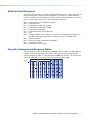
Input sync detection
View all input connections
Frq00•X1^1X1^2 ... X1^8]
0LS
Each X1^ is the connection status of an
input, starting from input 1.
NOTE: The “Frq00•” portion of the response appears only when the switcher is in Verbose mode 2 or 3.
Example:
0LS
No input detected
Sync detected
Response Status: 0 0 0 1 1 1 0 1
Input: 1 2 3 4 5 6 7 8
XTP/HDBaseT/XTP switch positions
Check input switch position
EIX1&HDBT}
X1*]
HdbtIX1&*X1*]
Check output switch position
EOX1(HDBT}
X1*]
HdbtOX1(*X1*]
NOTE:
Verbose mode 0 and 1.
Verbose mode 2 and 3.
Verbose mode 0 and 1.
Verbose mode 2 and 3.
X! = Input number
X@ = Output number
X1! = HDCP status (for inputs)
01 – 08
01 – 04
0 = No source device connected
2 = Source connected is not HDCP-compliant
1 = Source connected is HDCP-compliant
X1@ = HDCP status (for outputs)
0 = No monitor connected
1 = Monitor connected, does not support HDCP
2 = Monitor connected, supports HDCP, ,the video signal is not encrypted
3 = Monitor connected, supports HDCP, the video signal is encrypted
X1# = Video format
0 = Auto (HDMI RGB Full to CEA sink or DVI to non-CEA sink)
1 = DVI (RGB 444, no audio, no InfoFrames)
2 = HDMI RGB Full (RGB 444, 000 - 255 audio, InfoFrames)
3 = HDMI RGB Limited (RGB 444, 016 - 255 audio, InfoFrames)
4 = HDMI YUV Full (RGB 444, 000 - 255 audio, InfoFrames)
5 = HDMI YUV Limited (RGB 444, 016 - 255 audio, InfoFrames)
6 = HDMI YUV Full (RGB 422, 000 - 255 audio, InfoFrames)
7 = HDMI YUV Limited (RGB 422, 016 - 255 audio, InfoFrames)
X1$ = Output video bit depth
0 = Auto (default)
1 = 8-bit
X1% = Video mute status
0 = No mutes
1 = Video mute
2 = Video and sync
X1^ = Input signal status
0 = No signal detected
1 = Sync detected
X1& = TP and insertion input number
07 or 08
X1* = Switch position
0 = DTP
1 = HDBT (output only)
2 = XTP
X1( = TP (scaled) and insertion output number 03 or 04
DTP Crosspoint 84 IPCP Series Matrix Switchers • Programming Guide
12
Command and Response Table for Matrix Switcher Commands (continued)
Command Function
SIS Command
Response
(Host to Unit)
(Unit to Host)
Additional description
Names
NOTE:The HTML language reserves certain characters for specific functions (see Special Characters on page 20).
Write input name
Example:
Read input name
Write output name
Example:
Read output name
Write preset name
Example:
Read preset name
Example:
Write EDID name
EX!,X2)NI}
NmiX!,X2)]
E1,Podium camNI}
EX!NI}
Nmi01,Podium cam]
EX@,X2)NO}
E1,Main PJ1NO}
NmoX@,X2)]
EX@NO}
X2)]
EX2@,X2)NG}
E1,Security 1NG}
EX2@NG}
E2NG}
E2X#*X2)UNAM}
NmgX2@,X2)]
Name input 1 “Podium cam”.
X2)]
Nmo01,Main PJ1]
Nmg01,Security 1]
Name output 1 “Main PJ1”.
Name preset 1 “Security 1”.
X2)]
Security 2]
UnamX#*X2)]
NOTE: For the Write, Clear, and Read EDID Name commands, X# is valid only in the range of 75 through 82 (User EDID slots 1 through 8).
EE75*Slot 1UNAM}
Unam75*Slot 1]
Name EDID location 75 “Slot 1“.
Clear EDID name
EEX#*•UNAM}
UnamE75*USER n]
n = 1 through 8.
Read EDID name
EEX#UNAM}
X2)]
Write scaler preset name
E2*X2@,X2)PNAM}
Pnam2*X2@,X2)]
E2*5,preset 1PNAM}
Pnam2*005,preset 1]
E2*X2@PNAM]
X2)]
1X
Exe1]
2X
Exe2]
0X
Exe0]
X
X2!]
Example:
Example:
Read scaler preset name
Name scaler preset 5 “preset 1”.
Executive modes
Lock all front panel functions
Lock advanced front panel functions
Unlock all front panel functions
View lock status
NOTE:
X! = Input number
X@ = Output number
X# = EDID value (resolution and rate)
X1& = TP and insertion input number
X1* = Switch position
X1( = TP (scaled) and insertion output number
X2) = Name
X2! = Lock mode
X2@ = Scaler preset
Enable Lock mode 1.
Enable Lock mode 2.
Enable Lock mode 0.
00 – 08 (00 = untied input)
01 – 04 (00 = untied output)
See table 1 on page 10.
07 or 08
0 = DTP
1 = HDBT (output only)
2 = XTP
03 or 04
Up to 12 upper- and lower-case alphanumeric characters and _ / and spaces
0 = Mode 0
1 = Mode 1
2 = Mode 2 (default)
001 – 128
DTP Crosspoint 84 IPCP Series Matrix Switchers • Programming Guide
13
Command and Response Table for Matrix Switcher Commands (continued)
Command Function
SIS Command
Response
(Host to Unit)
(Unit to Host)
I
DTPCP84]
N
60-nnnn-nn]
Additional description
Information requests
Information request
Request part number
See the Extron website for the part
number.
NOTE: There are up to three separate sets of Extron firmware on which the switcher can report: the controller firmware, which is the
overall control firmware; the Ethernet protocol firmware, which handles the Ethernet interface; and the latest optional Extron firmware
update, which is available at www.extron.com.
Query controller firmware version
Example:
X2#]
1.23]
Q
The factory-installed controller firmware
version is 1.23 (sample value only).
X2#-X2$-X2$]
0Q
Query controller firmware version
Detailed status of the controller firmware
(verbose)
and any firmware upgrade. The active
firmware is marked by an asterisk (*).
A caret (^) indicates a bad checksum
or an invalid load. ?.?? indicates that
firmware is not loaded.
Response description: Ethernet protocol firmware version-controller firmware version-updated firmware version
See below
0q
Example:
Q
Description
* indicates the version running
Upload date and time
1.23-1.00(1.06LX-DTPCP84 -Tue, 08 Apr 2014 00:00:00 UTC)-1.00*(1.06LX-DTPCP84 -Mon, 21 Apr 2014 16:39:21 UTC)
Ethernet protocol
firmware
Request system status
DTP CrossPoint firmware version
Updated firmware version
Sts00*X2%•X2^•X2&•X2&]
S
NOTE: The “Sts00*” portion of the response appears only when the switcher is in Verbose mode 2 or 3.
Response description: Power supply•Temperature Celsius•Fan 1 RPM•Fan 2 RPM]
S
Example:
Temperature is 35.0 °C Fan 2 rotating at 2004 RPM
12.25•35.00•1976•2004
Power supply at 12.25V
View and erase file directory
NOTE: The response to the View File Directory command differs, depending on whether the command is sent via an RS-232 or Telnet
connection or sent via a Web browser connection.
View file directory
RS-232 port and Telnet
EDF}
See below:
List user-supplied files.
filename1•date/time•length]
filename2•date/time•length]
•
•
•
•
filenamen•date/time•length]
# of•Bytes•Left]]
View file directory
Web browser
EDF}
See below:
List user-supplied files.
Var•file•=•new•array•();
File•[1]•=•‘filename1,date1,filesize1‘;
File•[2]•=•‘filename3,date3,filesize3‘;
•
•
•
•
File•[n]•=•‘filenamen,daten,filesizen‘;
File•[n+1]•=•# of•Bytes•Left
Erase user-supplied web page/files
NOTE:
EfilenameEF}
Del•filename]
X2# = Firmware version number to second decimal place (x.xx)
X2$ = Verbose firmware version-description-upload date/time.
X2% = Voltage
Positive or negative voltage and magnitude
X2^ = Internal temperature
Degrees Celsius
X2& = Fan speed
RPM
DTP Crosspoint 84 IPCP Series Matrix Switchers • Programming Guide
14
Command and Response Table for Matrix Switcher Commands (continued)
Command Function
SIS Command
Response
(Host to Unit)
(Unit to Host)
Additional description
Scaler Output Commands
Brightness
EX1(*X2*BRIT}
EX1(+BRIT}
EX1(–BRIT}
EX1(BRIT}
BritX1(*X2*]
EX1(*X2*CONT}
EX1(+CONT}
EX1(–CONT}
EX1(CONT}
ContX1(*X2*]
EX1(*X2*HDET}
EX1(+HDET}
EX1(–HDET}
EX1(HDET}
HdetX1(*X2*]
Specify a value
EX1(*X2(HCTR}
HctrX1(*X2(]
Increment value
EX1(–HCTR}
HctrX1(*X2(]
Decrement value
EX1(+HCTR}
HctrX1(*X2(]
View
EX1(HCTR}
X2(]
Specify a value
EX1(*X2(VCTR}
VctrX1(*X2(]
Increment value
Decrement value
View
EX1(+VCTR}
EX1(–VCTR}
EX1(VCTR}
VctrX1(*X2(]
Specify a value
Increment value
EX1(*X2(HSIZ}
EX1(–HSIZ}
HsizX1(*X2(]
Decrement value
EX1(+HSIZ}
HsizX1(*X2(]
View
EX1(HSIZ}
X2(]
Specify a value
Increment value
EX1(*X2(VSIZ}
EX1(–VSIZ}
VsizX1(*X2(]
Decrement value
EX1(+VSIZ}
VsizX1(*X2(]
View
EX1(VSIZ}
X2(]
Set a specific brightness value
Increment brightness value
Decrement brightness value
View the brightness value
BritX1(*X2*]
BritX1(*X2*]
X2*]
Specify the brightness adjustment.
Increase the brightness setting by one.
Decrease the brightness setting by one.
Show the brightness setting.
Contrast
Set a specific contrast value
Increment contrast value
Decrement contrast value
View the contrast value
ContX1(*X2*]
ContX1(*X2*]
X2*]
Specify the contrast adjustment.
Increase the contrast setting by one.
Decrease the contrast setting by one.
Show the contrast setting.
Detail
Set a specific detail value
Increment detail value
Decrement detail value
View the detail value
HdetX1(*X2*]
HdetX1(*X2*]
X2*]
Specify the detail adjustment.
Increase the detail setting by one.
Decrease the detail setting by one.
Show the detail setting.
Horizontal shift
Set the horizontal location of first active
pixel in output X1(.
Increment the value by one pixel (shift
the image to the right).
Decrement the value by one pixel (shift
the image to the left).
Show the horizontal location of first
active pixel in output X1(.
Vertical shift
VctrX1(*X2(]
X2(]
Set the vertical location of first active line
in output X1(.
Increment the value by one line (shift up).
Decrease the value by one line (shift down).
Show the vertical location of first active
line in output X1(.
Horizontal size (image)
HsizX1(*X2(]
Set the horizontal of output X1(.
Increment the value by one pixel (make
one pixel wider).
Decrement the value by one pixel (make
one pixel narrower).
Show the horizontal size of output X1(.
Vertical size (image)
NOTE:
X1( = TP (scaled) and insertion output number
X2* = Picture adjustments
X2( = Position and size
VsizX1(*X2(]
Set the vertical of output X1(.
Increment the value by one pixel (make
one pixel taller).
Decrement the value by one pixel (make
one pixel shorter).
Show the vertical size of output X1(.
03 or 04
000 through 127 (064 = default)
±10240 (Horizontal is specified from left, vertical from top)
DTP Crosspoint 84 IPCP Series Matrix Switchers • Programming Guide
15
Command and Response Table for Matrix Switcher Commands (continued)
Command Function
SIS Command
Response
(Host to Unit)
(Unit to Host)
Additional description
Compound image position and size
Specify all size and position values
EX1(,X2(*X2(*X2(*X2(XIMG}
XimgX1(,X2(*X2(*X2(*X2(]
Example:
E3,+0*+0*2000*1000XIMG}
Ximg3,+00000*+00000*02000*01000]
View all size and position values
EX1(XIMG}
X2(*X2(*X2(*X2(]
EX1(APIX}
ApixX1(*X3)]
View active pixels and lines
View active pixels
NOTE: The “ApixX1(*” portion of the response appears only when the switcher is in Verbose mode 2 or 3.
View active lines
EX1(ALIN}
AlinX1(*X3)]
NOTE: The “AlinX1(*” portion of the response appears only when the switcher is in Verbose mode 2 or 3.
View defaults
EVX1(SPEC}
Show active pixels, active lines, total
SpecVX1(*X3)*X3)*X2(*X2(] pixels, and total lines.
NOTE: The “SpecVX1(*” portion of the response appears only when the switcher is in Verbose mode 2 or 3.
Aspect ratio
Set to fill
Set to follow
View aspect ratio
EX1(*1ASPR}
EX1(*2ASPR}
EX1(ASPR}
AsprX1(*1]
X1(*A
ImgX1(]
AsprX1(*2]
Always fill the output.
Follow the input aspect ratio.
X3!]
Execute Auto-Image
Execute Auto-Image
Overscan
NOTE: The Overscan command applies to SMPTE input rates only (NTSC or PAL, 480p to 1080p, 50 Hz or 60 Hz).
Set overscan value
Read overscan value
E6*X3@OSCN}
E6OSCN}
Oscn6*X3@]
X3@]
Save and recall scaler presets
NOTE: If you try to recall a scaler preset that is not saved, the matrix switcher responds with the error code E13.
Save a scaler preset
Recall a scaler preset
Example:
2*X1(*X2@,
2SprX1(*X2@]
2*X1(*X2@.
2RprX1(*X2@]
2*3*5.
2Rpr3*005]
Erase a scaler preset
Show scaler preset availabilities
EX2*X2@PRST}
PrstX2*X2@]
51#
PreIX%1X%2X%3 ... X%128]
Command character is a comma.
Command character is a period.
Recall preset 5, which becomes the
current configuration.
Each X% is the availability status of a
scaler preset, starting from preset 1.
NOTE: The “PreI” portion of the response appears only when the switcher is in Verbose mode 2 or 3.
Auto memories
Enable auto memories
EX1(*1AMEM}
AmemX1(*1]
Disable auto memories
Show auto memory status
EX1(*0AMEM}
EX1(AMEM}
AmemX1(*0]
NOTE:
Set auto memories on. Previous settings
for the incoming signal are recalled.
Set auto memories off.
X1(]
X% = Available
0 = Not available
1 = Available
X1( = TP (scaled) and insertion output number03 or 04
X2* = Picture adjustments
000 through 127 (064 = default
X2( = Position and size
±10240
Horizontal is specified from left, vertical from top
X3) = Active pixels and active lines
Dependent on the input signal and selected scaling.
X3@ = Overscan percentage
0 = 0% (default)
1 = 2.5% 2 = 5.0%
X3! = Aspect ratio fill or follow 1= fill; 2 = follow
X2@ = Scaler preset
001 – 128
DTP Crosspoint 84 IPCP Series Matrix Switchers • Programming Guide
16
Command and Response Table for Matrix Switcher Commands (continued)
Command Function
SIS Command
Response
(Host to Unit)
(Unit to Host)
EX1(*X3#TEST}
EX1(*0TEST}
EX1(TEST}
TestX1(*X3#]
Additional description
Test pattern
Enable a test pattern
Disable test patterns
View test pattern selection
TestX1(*0]
X3#]
Screen saver timeout and status
Set screen saver to go black
immediately
Set screen saver timeout duration
Example:
ETX1(*0SSAV}
SsavTX1(*000]
ETX1(*X3$SSAV}
ET3*300SSAV}
SsavTX1(*X3$]
Set screen saver to never go black
View screen saver timeout duration
View screen saver status
ETX1(*501SSAV}
ETX1(SSAV}
ESX1(SSAV}
SsavTX1(*501]
Set scaler output rate
Example:
EX1(*X3^RATE}
E3*75RATE}
RateX1(*X3^]
View scaler output rate
EX1(RATE}
X3^]
SsavT3*300]
Disable sync whenever no input video is
selected.
Blank output X1( after X3$ seconds.
Blank output 3 after 300 seconds
(5 minutes).
Do not blank output X1(.
X3$]
X3%]
Scaler output rate
Rate3*73]
Set the scaler to output X3^ on output X1(.
Set the scaler to output 720p video at
60 Hz on output 3.
RS-232 Insertion Commands
Captive screw and Ethernet serial port insertion enables
Enable an input captive screw serial
port insertion
EIX1&*0LRPT}
LrptIX1&*0]
Enable an input Ethernet serial port
insertion
EIX1&*1LRPT}
LrptIX1&*1]
Set all RS-232 input insertions
View input insertion
View all input insertions
EIX3&*LRPT}
EIX1&LRPT}
EILRPT}
LrptIX3&]
Enable an output captive screw
serial port insertion
EOX1(*0LRPT}
LrptOX1(*0]
Enable an output Ethernet serial
port insertion
EOX1(*1LRPT}
LrptOX1(*1]
Set all RS-232 output insertions
View RS-232 output insertion
View all output insertions
EOX3&*LRPT}
EOX1(LRPT}
EOLRPT}
LrptOX3&]
NOTE:
X1& = TP and insertion input number
X1( = TP (scaled) and insertion output number
X3$ = Duration
X3% = Screen saver status
X3^ = Scaler output resolution and rate
X3& = Captive screw or UART
X3# = Test pattern
X3&]
X3&7X3&8]
X3&]
X3&3X3&4]
Enable the captive screw serial port
insert on input X1&. This disables the
Ethernet RS-232 insert.
Enable the Ethernet serial port insert
on input X1&. This disables the captive
screw serial port insert.
One X3& for both available inputs,
starting at input 7.
Enable the captive screw serial port
insert on output X1(. This disables the
Ethernet serial port insert.
Enable the Ethernet serial port insert
on output X1(. This disables the
captive screw serial port insert.
One X3& for both available outputs,
starting at output 3.
07 or 08
03 or 04
0 = Output sync instantly disabled when no active video input is selected
001 through 500 (seconds)
501 = Output sync never times out (default)
0 = Active input detected, timer is not running
1 = No active input, timer is running, output sync is still active
2 = No active input, timer is expired, output sync is disabled.
See the table on page 58.
0 = Captive screw RS-232 insert
1 = Ethernet RS-232 insert (UART) (default)
00 = Disable (default)
04 = Color bars
01 = Crop
05 = Grayscale
02 = Alternating pixels
06 = Blue mode
03 = Crosshatch
07 = Crop and pink noise (Ch. 1/2, 48 Hz, 24-bit)
DTP Crosspoint 84 IPCP Series Matrix Switchers • Programming Guide
17
Command Function
SIS Command
Response
(Host to Unit)
(Unit to Host)
Additional description
Ethernet and serial port insert parameters
Set serial port parameters
EX3**X3(,X4),X4!,X4@CP}
Read serial port parameters
EX3*CP}
Configure current port timeout
Read current port timeout
Configure global IP port timeout
Read global IP port timeout
Set UART start point
E0*X4#TC}
E0TC}
E1*X4#TC}
E1TC}
EX4%MD}
X3(,X4),X4!,X4@]
Pti0*X4#]
X4#]
Pti1*X4#]
X4#]
PmdX4%]
Read UART start point
EMD}
X4%]
CpnX3*•CcpX3(,X4),X4!,X4@]
NOTE:
X3* = Port #
Sets the initial (lowest) port number for
the range of numbers assigned to the
serial port and UARTs.
01 = Remote (RS-232) port
02 — 05 = UARTs 1 — 5 (DTP input and output ports)
300, 600, 1200, 1800, 2400, 3600, 4800, 7200, 9600, 14400, 19200,
28800, 38400, 57600, 115200 (default=9600)
X3( = Baud rate
X4) = Parity
X4! = Data bits
X4@ = Stop bits
X4# = Port timeout interval (in 10-second increments)
X4% = UART starting point
odd, even, none, mark, space (only the first letter required) (n = default)
7, 8
1, 2
1 (= 10 seconds) - 65000 (default is 30 = 300 seconds = 5 minutes)
The starting point (X4%) is the rear panel Remote RS-232 port.
The next two positions (X4%+1 and X4%+2) are DTP inputs.
The next two positions (X4%+3 and X4%+4) are DTP outputs.
Default values:
2000 = Rear panel Remote (RS-232) port
2001 and 2002 = Input 7 and input 8
2003 and 2004 = Output 3 and output 4
IP Port Specific SIS Commands
The DTP CrossPoint 84 includes a built-in IPCP Pro control processor that supports the
LAN ports and other functionality. See the IPCP Pro Series User Guide at www.extron.com
for SIS commands unique to the IPCP control processor.
DTP Crosspoint 84 IPCP Series Matrix Switchers • Programming Guide
18
Remote Port Specific and Communications Protocol SIS Commands
Symbol definitions for Remote port specific SIS commands
X5)=Password
Up to 12 alphanumeric characters
NOTE:The HTML language reserves certain characters for specific functions (see Special
Characters on page 20).
X5! = Port number
01 = Remote (RS-232) port
02 — 05 = UARTs 1 — 5 (DTP input and output ports)
X5@ = Baud rate
X5#=Parity
X5$ = Data bits
X5% = Stop bits
9600 (default), 19200, 38400, 115200
odd, even, none, mark, space (only the first letter required) (n = default)
7, 8 (default)
1 (default), 2
NOTE: X5! through X5% and X5* are variables for the rear panel Remote RS-232 port. These variables are repeated on page 8 as X3*
through X4# for the RS-232 inserts.
X5^ = Port type
X5& = Verbose mode
0 = RS-232 (default)
1 = RS-422 (not available on DTP CrsossPoint)
0 = Clear or none (default for Telnet connection)
1 = Verbose mode (default for RS-232 or USB connection)
2 = Tagged responses for queries
3 = Verbose mode and tagged for queries
NOTE: If tagged responses is enabled (modes 2 and 3), all read commands return the constant string and the value as the set command
does (for example, the read matrix name command ECN}, returns Ipn•X2)]).
X5* = Port timeout interval (in 10-second increments)
1 (= 10 seconds) - 65000 (default is 30 = 300 seconds = 5 minutes)
SIS Command and Response Table for Remote and Communications Protocol Commands
Command Function
SIS Command
Response
(Host to Unit)
(Unit to Host)
Additional description
Read serial port parameters
EX5)CA}
Ipa•X5)]
ECA}
X5)]
E•CA}
Ipa•]
EX5)CU}
Ipu•X5)]
ECU}
X5)]
E•CU}
Ipu•]
EX5!*X5@,X5#,X5$,X5%CP}
CpnX5!•CcpX5@,X5#,X5$,X5%]
EX5!CP}
X5@,X5#,X5$,X5%]
Configure flow control
Read flow control
Configure receive timeout
EX5!*Y8^,Y8&CF}
EX5!CF}
EX5!*Y8*,Y8(CE}
Set administrator password
Read administrator password
Reset (clear) administrator password
Set user password
Read user password
Reset (clear) user password
Set serial port parameters
CpnX5!•CflY8^,Y8&]
Y8^,Y8&]
CpnX5!•CceY8*,Y8(,Y9),Y9!]
NOTE: The configure command is sufficient as shown for most users, with the priority (Y9)) and length or delimiter (Y9!) omitted).
The response in this case is “CpnX5!•CceY8*,Y8(,0,00000L],” with the default Y9) and Y9! values returned.
Read receive timeout
Set mode
Read mode
Set verbose mode
Read verbose mode
Configure current port timeout
Read current port timeout
Configure global IP port timeout
Read global IP port timeout
EX5!CE}
EX5!*X5^CY}
EX5!CY}
EX5&CV}
ECV}
E0*X5*TC}
E0TC}
E1*X5*TC}
E1TC}
Y8*,Y8(,Y9),Y9!]
CpnX5!•CtyX5^]
X5^]
VrbX5&]
X5&]
Pti0*X5*]
X5*]
Pti1*X5*]
X5*]
DTP Crosspoint 84 IPCP Series Matrix Switchers • Programming Guide
19
Special Characters
The HTML language reserves certain characters for specific functions. The switcher does
not accept these characters as part of names, passwords, or locally created file names.
The switcher rejects the following characters:
{space (spaces are Ok for names)} + ~ , @ = ‘ [ ] { } < > ’ “ semicolon (;) colon (:)
| \ and ?.
DTP Crosspoint 84 IPCP Series Matrix Switchers • Programming Guide
20
DSP SIS
Commands
Command and Response Table for SIS Commands
Many digital signal processor (DSP) functions; gain (which includes the mix-points), trim, mutes,
and group masters 1 and 2; can be controlled using SIS commands. These commands
follow the same general rules as basic SIS commands, but the variables (Y/s) tend to be
more complex. Also, a comprehensive understanding of the audio signal flow of the DSP is
helpful to understanding these commands. Thumbnails of the controls are provided in the
tables that follow for reference
Symbol Definitions
]
}
= Carriage return (no line feed)
|
= Pipe (can be used interchangeably with the } character)
•
= space
= Carriage return and line feed
E = Escape key
W
= Can be used interchangeably with the E character
X6) = Object ID (gain control or mix-point)
X6! = Level value; depends on control
See the tables on pages XX through XX.
-100.0 dB to +80.0 dB, in 0.1 dB increments. Example: 56 = 5.6 dB.
NOTE:The valid range of the level for a specific control depends on the control addressed.
X6@ = Mute and phantom power status
X6# = Group master group number
X6$ = Group fader setting
X6% = Group fader increment
X6^ = Group fader soft limit
X6& = Group type
0 = unmute (pass audio) or off
1 = mute or on
01 – 32
dB value, in 0.1 dB increments. The valid range depends on the type of gain block
dB value, in 0.1 dB increments, to raise or lower a group fader
dB value, in 0.1 dB increments. X6^ must be within the range for the gain block
grouped in X6#.
6= gain
12 = mute
DTP Crosspoint 84 IPCP Series Matrix Switchers • DSP SIS Commands
21
Line Input Gain Blocks
Input 1
Gain
Trim
Input 5
Gain
Trim
Left
30000
30100
Left
30008
30108
Right
30001
30101
Right
30009
30109
Input 2
Gain
Trim
Input 5
Gain
Trim
Left
30002
30102
Left
30010
30110
Right
30003
30103
Right
30011
30111
Input 3
Gain
Trim
Input 7
Gain
Trim
Left
30004
30104
Left
30012
30112
Right
30005
30105
Right
30013
30113
Input 4
Gain
Trim
Input 8
Gain
Trim
30014
30114
30015
30115
Left
30006
30106
Left
Right
30007
30107
Right
Mic Input Gain Blocks
Input
Premixer
Input
Gain
Pre-mixer
Gain
Input 1
40000
40100
Input 2
40001
40101
Input
Gain
Pre-mixer
Gain
Input 3
40002
40102
Input 4
40003
40103
DTP Crosspoint 84 IPCP Series Matrix Switchers • DSP SIS Commands
22
Post-switcher Gain Blocks
Output 1
Gain
Left
50000
Right
Output 2
Output 3
Gain
Left
50004
50001
Right
50005
Gain
Output 4
Gain
Left
50002
Left
50006
Right
50003
Right
50007
Virtual Returns and Expansion Inputs Gain Blocks
Gain
Gain
Virtual Return A
50100
Expansion Input 1
50200
Virtual Return B
50101
Expansion Input 2
50201
Virtual Return C
50102
Expansion Input 3
50202
Virtual Return D
50103
Expansion Input 4
50203
Virtual Return E
50104
Expansion Input 5
50204
Virtual Return F
50105
Expansion Input 6
50205
Virtual Return G
50106
Expansion Input 7
50206
Virtual Return H
50107
Expansion Input 8
50207
DTP Crosspoint 84 IPCP Series Matrix Switchers • DSP SIS Commands
23
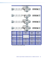
Switcher-to-output mixer block (A)
Mixer blocks, part 1
Out 1
Out 2
Out 3
Out 4
Out 5
Out 6
Out 7
Out 8
Output 1
Left
20000
Right
20101
Output 2
Left
20202
Right
20303
Output 3
A
Left
20404
Right
20505
Output 4
B
Left
20606
Right
20707
Mic-to-output mixer block (B)
C
Mic in 1
20800
20801
20802
20803
20804
20805
20806
20807
Mic in 2
20900
20901
20902
20903
20904
20905
20906
20907
Mic in 3
21000
21001
21002
21003
21004
21005
21006
21007
Mic in 4
21100
21101
21102
21103
21104
21105
21106
21107
Virtual returns-to-output mixer block (C)
D
V. rtn A
21200
21201
21202
21203
21204
21205
21206
21207
V. rtn B
21300
21301
21302
21303
21304
21305
21306
21307
V. rtn C
21400
21401
21402
21403
21404
21405
21406
21407
V. rtn D
21500
21501
21502
21503
21504
21505
21506
21507
V. rtn E
21600
21601
21602
21603
21604
21605
21606
21607
V. rtn F
21700
21701
21702
21703
21704
21705
21706
21707
V. rtn G
21800
21801
21802
21803
21804
21805
21806
21807
V. rtn H
21900
21901
21902
21903
21904
21905
21906
21907
Expansion inputs-to-output mixer block (D)
Exp. in 1
22000
22001
22002
22003
22004
22005
22006
22007
Exp. in 2
22100
22101
22102
22103
22104
22105
22106
22107
Exp. in 3
22200
22201
22202
22203
22204
22205
22206
22207
Exp. in 4
22300
22301
22302
22303
22304
22305
22306
22307
Exp. in 5
22400
22401
22402
22403
22404
22405
22406
22407
Exp. in 6
22500
22501
22502
22503
22504
22505
22506
22507
Exp. in 7
22600
22601
22602
22603
22604
22605
22607
22607
Exp. in 8
22700
22701
22702
22703
22704
22705
22706
22707
DTP Crosspoint 84 IPCP Series Matrix Switchers • DSP SIS Commands
24
Switcher-to-virtual-send-bus mixer block (E)
Mixer blocks,
part 2
V. Send A
Out 2
Out 3
Out 4
Out 5
Out 6
Out 7
Out 8
Left
20008
20009
20010
20011
20012
20013
20014
20015
Right
20108
20109
20110
20111
20112
20113
20114
20115
Left
20208
20209
20210
20211
20212
20213
20214
20215
Right
20308
20309
20310
20311
20312
20313
20314
20315
Left
20408
20409
20410
20411
20412
20413
20414
20415
Right
20508
20509
20510
20511
20512
20513
20514
20515
Left
20608
20609
20610
20611
20612
20613
20614
20615
Right
20708
20709
20710
20711
20712
20713
20714
20715
Output 1
Output 2
Output 3
E
Output 4
F
Mic-to-virtual-send-bus mixer block (F)
G
Mic in 1
20808
20809
20810
20811
20812
20813
20814
20815
Mic in 2
20908
20909
20910
20911
20912
20913
20914
20915
Mic in 3
21008
21009
21010
21011
21012
21013
21014
21015
Mic in 4
21108
21109
21110
21111
21112
21113
21114
21115
V. rtn A
21208
21209
21210
21211
21212
21213
21214
21215
V. rtn B
21308
21309
21310
21311
21312
21313
21314
21315
V. rtn C
21408
21409
21410
21411
21412
21413
21414
21415
V. rtn D
21508
21509
21510
21511
21512
21513
21514
21515
V. rtn E
21608
21609
21610
21611
21612
21613
21614
21615
V. rtn F
21708
21709
21710
21711
21712
21713
21714
21715
V. rtn G
21808
21809
21810
21811
21812
21813
21814
21815
V. rtn H
21908
21909
21910
21911
21912
21913
21914
21915
Virtual returns-to-virtual-send-bus mixer block (G)
H
Expansion inputs-to-virtual-send-bus mixer block (H)
Exp. in 1
22008
22009
22010
22011
22012
22013
22014
22015
Exp. in 2
22108
22109
22110
22111
22112
22113
22114
22115
Exp. in 3
22208
22209
22210
22211
22212
22213
22214
22215
Exp. in 4
22308
22309
22310
22311
22312
22313
22314
22315
Exp. in 5
22408
22409
22410
22411
22412
22413
22414
22415
Exp. in 6
22508
22509
22510
22511
22512
22513
22514
22515
Exp. in 7
22608
22609
22610
22611
22612
22613
22614
22615
Exp. in 8
22708
22709
22710
22711
22712
22713
22714
22715
DTP Crosspoint 84 IPCP Series Matrix Switchers • DSP SIS Commands
25
Line Output Gain Blocks
Output 1
Trim
Amp Output
Analog Volume
HDMI Volume
Left
60100
60300
60000
60200
Right
60101
60301*
60001
60201
Output 2
Trim
Analog Volume
HDMI Volume
Left
60102
60002
60202
Right
60103
60003
60203
Output 3
Trim
Analog DTP
Analog Volume
Digital DTP
Left
60104
60304
60004
60204
Right
60105
60305
60005
60205
Output 4
Trim
Analog DTP
Analog Volume
Digital DTP
Left
60106
60306
60006
60206
Right
60107
60307
60007
60207
* Not used on MA (mono amplifier) model.
DTP Crosspoint 84 IPCP Series Matrix Switchers • DSP SIS Commands
26
Command and Response Table for DSP SIS Commands
Command Function
SIS Command
Response
(Host to Unit)
(Unit to Host)
Additional description
Audio trim, gain, and mixing
NOTES:
•
•
•
•
The command format is the same, regardless of the control or mix-point that is to be set; the acceptable adjustment range varies
depending on the control or mix-point:
All X6! values are in 0.1 dB increments. Example: 56 = 5.6 dB.
The valid range of the level for a specific control depends on the control addressed:
• The line audio input gain range is –18 dB to +24 dB (X6! = –180 to +240).
• The mic input gain range is –18 dB to 80 dB (X6! = –180 to +800).
• The line input trim and line output trim range is –12 to +12 dB (X6! = –120 to +120).
• The mic pre-mixer gain, line out post-switcher gain, and pre-mixer gain range is –100 dB to +12 dB (X6! = –1000 to +120).
• The mix-points (with their associated mixing controls) range is –35 dB to +25 dB (X6! = –350 to +250).
• The line output gain range is –100 to 0 dB (X6! = –1000 to 0).
For attenuation, the negative sign (–) must be entered and is reported in the response. For gain, the positive sign (+) is optional and
is not returned in the response.
EGY6)*X6!AU}
DsGY6)*X6!]
Set object ID (Y6)) to a level of X6!.
EG30012*56AU}
DsG30012*56]
EG20800*–125AU}
DsG20800*–125]
EGY6)AU}
X6!]
Set the input 7 left gain to a value of
5.6 dB.
Set the mic input 1 gain to a level of
–12.5 dB.
Object ID Y6) is set to a value of X6!.
EG50005AU}
105]
EG60301AU}
–955]
Set a digital DSP trim, gain, or mixpoint
Example:
EHY6)*X6!AU}
DsHY6)*X6!]
EH60204*-780AU}
DsH60204*-780]
Read a digital DSP trim or mix-point
Example:
EHY6)AU}
EH30103AU}
X6!]
75]
EMY6)*1AU}
EM60006*1AU}
EMY6)*0AU}
EM40000*0AU}
EMY6)AU}
DsMY6)*1]
Set an analog DSP trim, gain, or
mix-point
Example 1:
Example 2:
Read an analog DSP trim or mixpoint
Example 1:
Example 2:
Post-switcher output 4 right is set to
+10.5 dB.
Set the output 1 amplified audio
output to -95 dB. This response is not
possible on an MA model switcher.
Set object ID (Y6)) to a level of X6!.
Set the output 3 left digital DTP gain to
a value of –78 dB.
Object ID Y6) is set to a value of X6!.
Line input 2 right trim is set to +7.5 dB.
Audio mute
Audio mute
Example:
Audio unmute
Example:
Read audio mute
DsM60006*1]
DsMY6)*0]
Mute object ID Y6).
Mute output 4, left, analog volume.
DsM40000*0}
Unmute object ID Y6).
Unmute mic input 1 gain (pass audio).
X6@]
X6@: 0 = mute off, 1 = mute on.
Phantom power
NOTE: The phantom power commands are valid only for the mic input gain object IDs (Y6)s 40000 through 40003).
Phantom power on
Example:
Phantom power off
Read phantom power status
EZY6)*1AU}
EZ40000*1AU}
EZY6)*0AU}
EZY6)AU}
DsZY6)*1]
DsZ40000*1]
DsZY6)*0]
DsZY6)*X6@]
Turn phantom power on for object ID Y6).
Turn phantom power on for mic 1.
Turn phantom power off for object ID Y6).
X6@: 0 = phantom power off,
1 = phantom power on.
DTP Crosspoint 84 IPCP Series Matrix Switchers • DSP SIS Commands
27
Command and Response Table for DSP SIS Commands (continued)
Command Function
SIS Command
Response
(Host to Unit)
(Unit to Host)
Additional description
Group masters
NOTES:
•
•
•
A group must have assigned members for these commands to have an effect.
For X6!, a positive (+) value is assumed unless a negative (-) value is specified.
If entering a X6! value outside the valid range for the group or outside the soft limits, the DTP CrossPoint responds with an invalid
parameter (E13) error.
Set a group fader control
Example:
EDX6#*X6!GRPM}
ED2*-293*GRPM}
GrpmDX6#*X6!]
Raise a group fader control
EDX6#*X6%+GRPM}
GrpmDX6#*X6$]
ED2*30+GRPM}
GrpmD*-263]
Lower a group fader control
EDX6#*X6%-GRPM}
GrpmDX6#*X6$]
View the group fader control level
EDX6#GRPM}
GrpmDX6#*X6!]
Mute a group mute control
Clear (unmute) a group mute control
View a group mute control
Set soft limits
EDX6#*1GRPM}
GrpmDX6#*1]
EDX6#*0GRPM}
GrpmDX6#*0]
EDX6#GRPM}
X6@]
ELX6#*X6^upper*X6^lowerGRPM}
GrpmLX6#*X6^*X6^]
EL2*+60*-60GRPM}
GrpmL2*60*–60]
Example:
Example:
View soft limits
ELX6#GRPM}
View group type
EPX6#GRPM}
View group members
EOX6#GRPM}
GrpmD2*-293]
Set the group fader to a value of X6!.
Set the group 2 fader control to
-29.3 dB.
Increase the level of the X6# group fader
by X6% dB.
Raise the group 2 fader 3 dB (from
-29.3 dB to -26.3 dB, starting from
the level set in the Set a group fader
control example, above.
Decrease the level of the X6# group
fader by X6% dB.
In verbose modes 1 and 2, the
response is simplified to X6$].
Mute all blocks in group X6#.
Umute all blocks in group X6#.
Set the groups soft limits to X6^ and X6^.
Set the upper soft limit for the group 2
fader to +6.0 dB and the lower limit to
-6.0 dB.
In verbose modes 0 and 1, the
GrpmLX6#*X6^*X6^]
response is simplified to X6^*X6^].
GrpmPX6#*X6&]
Show the group type (X6&) for group
X6#. In verbose modes 0 and 1, the
response is simplified to X6&].
Y6) is the control or mix-point. In
GrpmOX6#*Y6)1*Y6)2*...*Y6)16] verbose modes 0 and 1, the response is
simplified to Y6)1*Y6)2*...*Y6)16].
DTP Crosspoint 84 IPCP Series Matrix Switchers • DSP SIS Commands
28
Extron Warranty
Extron Electronics warrants this product against defects in materials and workmanship for a period of three years
from the date of purchase. In the event of malfunction during the warranty period attributable directly to faulty
workmanship and/or materials, Extron Electronics will, at its option, repair or replace said products or components,
to whatever extent it shall deem necessary to restore said product to proper operating condition, provided that it is
returned within the warranty period, with proof of purchase and description of malfunction to:
USA, Canada, South America,
and Central America:
Extron Electronics
1230 South Lewis Street
Anaheim, CA 92805
U.S.A.
Japan:
Extron Electronics, Japan
Kyodo Building, 16 Ichibancho
Chiyoda-ku, Tokyo 102-0082
Japan
Europe and Africa:
Extron Europe
Hanzeboulevard 10
3825 PH Amersfoort
The Netherlands
China:
Extron China
686 Ronghua Road
Songjiang District
Shanghai 201611
China
Asia:
Extron Asia Pte Ltd
135 Joo Seng Road, #04-01
PM Industrial Bldg.
Singapore 368363
Singapore
Middle East:
Extron Middle East
Dubai Airport Free Zone
F12, PO Box 293666
United Arab Emirates, Dubai
This Limited Warranty does not apply if the fault has been caused by misuse, improper handling care, electrical
or mechanical abuse, abnormal operating conditions, or if modifications were made to the product that were not
authorized by Extron.
NOTE: If a product is defective, please call Extron and ask for an Application Engineer to receive an RA (Return
Authorization) number. This will begin the repair process.
USA: 714.491.1500 or 800.633.9876
Asia:65.6383.4400
Europe:31.33.453.4040
Japan:81.3.3511.7655
Units must be returned insured, with shipping charges prepaid. If not insured, you assume the risk of loss or damage
during shipment. Returned units must include the serial number and a description of the problem, as well as the
name of the person to contact in case there are any questions.
Extron Electronics makes no further warranties either expressed or implied with respect to the product and its quality,
performance, merchantability, or fitness for any particular use. In no event will Extron Electronics be liable for direct,
indirect, or consequential damages resulting from any defect in this product even if Extron Electronics has been
advised of such damage.
Please note that laws vary from state to state and country to country, and that some provisions of this warranty may
not apply to you.
Extron Headquarters
Extron Europe
Extron Asia
Extron Japan
+1.800.633.9876 (Inside USA/Canada Only)
Extron USA - West
Extron USA - East
+1.714.491.1500+1.919.850.1000
+1.714.491.1517 FAX
+1.919.850.1001 FAX
+800.3987.6673
(Inside Europe Only)
+31.33.453.4040
+31.33.453.4050 FAX
+65.6383.4400
+65.6383.4664 FAX
+81.3.3511.7655
+81.3.3511.7656 FAX
Extron China
+86.21.3760.1568
+86.21.3760.1566 FAX
Extron Middle East
Extron Korea
Extron India
+971.4.299.1800
+971.4.299.1880 FAX
+82.2.3444.1571
+82.2.3444.1575 FAX
1800.3070.3777
(Inside India Only)
+91.80.3055.3777
+91.80.3055.3737 FAX
© 2014 Extron Electronics All rights reserved. www.extron.com