1
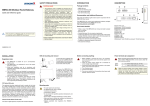
GCP-MG
Ethernet Modbus
gateway
User manual
Edition 1.1
October 2008
UMGCPMG-0801
GCP-MG Ethernet Modbus gateway: User manual
Copyright © 2007-2008 proconX Pty Ltd. All rights reserved.
Document revision history
2007-05-14, 1.0
Initial Release for hardware version J367-S3-PB and firmware version 1.0
2008-07-28, 1.1
LED description added. Added max. number of Modbus/TCP connections. Corrected weight. Updated company name and address. Editorial Changes.
No part of this material may be reproduced or transmitted in any form or by any means or used to make any derivative work without
express written consent from the copyright holders.
proconX and FieldTalk are trademarks of proconX Pty Ltd. All other product and brand names mentioned in this document may be trademarks or registered trademarks of their respective owners.
Disclaimer
proconX Pty Ltd makes no warranty for the use of its products, other than those expressly contained in the Company's standard warranty
which is detailed in the Terms and Conditions located on the Company's Website. The Company assumes no responsibility for any errors
which may appear in this document, reserves the right to change devices or specifications detailed herein at any time without notice,
and does not make any commitment to update the information contained herein. No licenses to patents or other intellectual property of
proconX are granted by the Company in connection with the sale of proconX products, expressly or by implication. proconX products are
not authorized for use as critical components in life support devices or systems.
Support & product feedback
We provide an electronic support and feedback system for our proconX products. It can be accessed through the following web link:
http://www.proconx.com/support
Your feedback and comments are always welcome. It helps improving this product.
Contact
For further information about the GCP-MG product or this document please contact us at:
proconX Pty Ltd
PO Box 791
Sumner QLD 4074
Australia
Website: http://www.proconx.com/gcpmg
Contents
About this manual ............................................................................................................ v
1 Introduction .................................................................................................................... 1
Features ..................................................................................................................... 2
2 Description ..................................................................................................................... 3
3 Installation ...................................................................................................................... 5
Safety precautions ..................................................................................................... 5
Regulatory notes ....................................................................................................... 5
Unpacking and handling .......................................................................................... 5
Before connecting anything ...................................................................................... 6
DIN rail mounting and removal ............................................................................... 6
Mounting rules .......................................................................................................... 7
Powering the GCP-MG ............................................................................................. 7
Wiring the CAN interface ......................................................................................... 7
Wiring the Modbus RS-485 interface ........................................................................ 8
Wiring the Modbus RS-232 interface ........................................................................ 9
Connecting Ethernet ................................................................................................ 10
Connecting to the diagnostic port .......................................................................... 10
4 Ethernet & IP configuration ......................................................................................... 13
IP setup using a web browser and a cross-over network cable .............................. 13
IP setup using HyperTerminal ................................................................................ 14
Temporarily changing the IP settings on your PC ................................................. 15
5 Web browser based management ................................................................................ 17
Connecting to the GCP-MG .................................................................................... 17
Monitoring and diagnostic ...................................................................................... 18
Device status ................................................................................................... 18
CAN communication status ............................................................................ 20
Finding the firmware version and serial number ........................................... 22
Configuring and commissioning ............................................................................ 22
Configuring Ethernet and IP .......................................................................... 22
Configuring GCP-30 and LS 4 Modbus access ............................................... 24
Configuring serial line Modbus ...................................................................... 25
Remote restarting the device .......................................................................... 26
6 Gateway operation ....................................................................................................... 27
LED indicators ......................................................................................................... 28
7 Modbus data organization ........................................................................................... 29
GCP-30 MUX data table 3:0001 .............................................................................. 31
Allocation with options SB03 and SC06 ......................................................... 34
GCP-30 floating point table 3:1001 ......................................................................... 34
GCP-30 remote control data table 4:0001 ................................................................ 35
LS 4 MUX data table 3:0001 .................................................................................... 36
LS 4 floating point data table 3:1001 ...................................................................... 37
LS 4 remote control data table 4:0001 ..................................................................... 38
8 Specifications ................................................................................................................ 41
Dimensions .............................................................................................................. 42
References ........................................................................................................................ 43
Glossary ........................................................................................................................... 45
Index ................................................................................................................................ 47
UMGCPMG-0801
iii
Figures
1.1 GCP-MG mounted on DIN rail .................................................................................. 1
2.1 Location of connectors ................................................................................................ 3
5.1 Device management and configuration via the web browser ................................... 17
5.2 Overwiew page ......................................................................................................... 18
5.3 Modbus status page .................................................................................................. 19
5.4 CAN communication status page ............................................................................. 21
5.5 About page ................................................................................................................ 22
5.6 Ethernet and IP settings page ................................................................................... 23
5.7 IP settings changed confirmation .............................................................................. 23
5.8 GCP-30 settings page ................................................................................................ 24
5.9 Modbus settings page ............................................................................................... 25
5.10 Restart device page .................................................................................................. 26
5.11 Restart confirmation page ....................................................................................... 26
6.1 Gateway operation .................................................................................................... 27
8.1 Enclosure dimensions ................................................................................................ 42
Tables
3.1 Power supply connector pinout .................................................................................. 7
3.2 CAN connector pinout ................................................................................................ 8
3.3 RS-485 connector pinout ............................................................................................. 8
3.4 Primary RS-232 (Modbus) connector pinout .............................................................. 9
3.5 Ethernet connector pinout ......................................................................................... 10
3.6 Secondary RS-232 (Diagnostic) connector pinout ..................................................... 11
6.1 LED diagnostic codes ................................................................................................ 28
7.1 Supported Modbus function codes ........................................................................... 29
7.2 Modbus slave ID relationship ................................................................................... 30
7.3 Modbus exception codes ........................................................................................... 31
7.4 Modbus addresses for GCP-30 MUX values ............................................................ 31
7.5 Modbus addresses for SB03 Cat CCM and SC06 MTU MDEC options ................... 34
7.6 Modbus addresses for GCP-30 floating point data table ......................................... 35
7.7 Modbus addresses for GCP-30 remote control ........................................................ 36
7.8 Modbus addresses for LS 4 MUX values ................................................................. 37
7.9 Modbus addresses for LS 4 floating point data table .............................................. 38
7.10 Modbus addresses for LS 4 remote control ........................................................... 39
iv
UMGCPMG-0801
About this manual
About this manual
This manual explains how to install, operate and configure a GCP-MG.
This manual is to be used with a GCP-MG with firmware version 1.0.
Document Conventions
Throughout this manual we use the following symbols and typefaces to make you aware
of safety or other important considerations:
Indicates a potentially hazardous situation that, if not avoided,
could result in death or serious injury.
Indicates a potentially hazardous situation that, if not avoided,
could result in damage to equipment.
Indicates information that is critical for successful application
and understanding of the product.
Provides other helpful user information that does not fall in
above categories.
Provides supplemental user information.
Acronym
This typeface is used to introduce acronyms or product names.
Command
This typeface is used to represent commands, prompts, input
fields and filenames. In the context of programming it is used
for functions, variable names, constants or class names.
Placeholder
This typeface is used to represent replacable text. Replaceable
text is a placeholder for data you have to provide, like filenames or command line arguments.
User input
This typeface is used to represent data entered by the user or
buttons.
Screen output
Screen output or program listing
UMGCPMG-0801
v
This page intentionally left blank
vi
UMGCPMG-0801
Introduction
Chapter 1. Introduction
The GCP-MG is a next-generation Modbus/CAN gateway specifically designed to interface
Woodward's GCP-30 Series Genset Controls and LS 4 Circuit Breaker Controls with Modbus
networks.
The GCP-MG gateway has been developed in cooperation with Woodward to ensure the
highest possible degree of interoperability with Woodward equipment.
The gateway features CAN, serial RS-232 and RS-485 ports as well as an Ethernet port
and can be mounted on a DIN rail. On the CAN side it implements the Woodward CAL
protocol to connect to the GCP controls. On the serial ports and on Ethernet it implements
a Modbus server (Modbus RTU and Modbus/TCP) and accepts connections from Modbus
master devices like PLCs and SCADA systems.
Usage and configuration of the gateway is simple and conveniently performed using a
web browser which connects to the embedded web server.
Figure 1.1: GCP-MG mounted on DIN rail
Possible areas of application are:
•
•
•
•
•
•
•
•
PLC connection
Operator panel interfacing
HMIs
SCADA integration
Power station automation
Gen set control
Remote control & monitoring
Data logging
UMGCPMG-0801
1
GCP-MG Ethernet Modbus gateway: User manual
Features
The GCP-MG GCP-MG gateway provides the following key features:
• Modbus/TCP protocol (Ethernet)
• Modbus RTU protocol (either RS-232 or RS-485, software configurable)
• Interfaces with up to 16 GCP-30 controls and up to 8 LS 4 controls
• Full support of Option SB03 (Cat CCM) and Option SC06 (MTU MDEC)
• GW4 backward compatible Modbus register layout
• Dedicated Modbus slave ID for each GCP-30 and LS 4 control
• Complete data set of one GCP-30 unit can be read with a single Modbus transaction
• Integer/Exponent value pairs for voltages, power and currents are additionally represented as 32-bit floating point registers
• Serial baud rate up to 115200 bps
• Support of Modbus function codes 03, 04, 06 and 16
• Concurrently one Modbus serial line and up to two Modbus/TCP connections
• Embedded web server for easy configuration and commissioning using a web browser
• Firmware upgradeable via Ethernet
• DIN rail mountable
• 24 V DC (10-30 V) power supply
• Status LEDs for power, Ethernet link, device status and Modbus/CAN status
2
UMGCPMG-0801
Description
Chapter 2. Description
The power, CAN and RS-485/RS-422 connectors are placed on the top side of the module.
The RS-232 and Ethernet connectors are placed on the bottom side of the module as shown
in the following illustration:
TOP VIEW
BOTTOM VIEW
FRONT VIEW
Figure 2.1: Location of connectors
Clear front cover
Primary RS-232 (Modbus) connector
Secondary RS-232 (Diagnostic) connector
Ethernet connector
DIN rail clip
Power LED
Ethernet link LED
Device status LED
Modbus/CAN status LED
Power terminal block socket
Modbus RS-485 terminal block socket
CAN connector
UMGCPMG-0801
3
This page intentionally left blank
4
UMGCPMG-0801
Installation
Chapter 3. Installation
Safety precautions
HAZARD OF ELECTRIC SHOCK, EXPLOSION, OR ARC FLASH
• Only qualified workers should install this equipment. Such work should be performed only after reading this entire set of instructions.
• NEVER work alone.
• Before performing visual inspections, tests, or maintenance on this equipment, disconnect all sources of electric power. Assume that all circuits are live until they
have been completely de-energized, tested, and tagged. Pay particular attention
to the design of the power system. Consider all sources of power, including the
possibility of backfeeding.
• Apply appropriate personal protective equipment and follow safe electrical practices.
• Turn off all power supplying the equipment in which the GCP-MG is to be installed
before installing and wiring the GCP-MG.
• Always use a properly rated voltage sensing device to confirm that power is off.
• Beware of potential hazards, wear personal protective equipment, and carefully
inspect the work area for tools and objects that may have been left inside the equipment.
• The successful operation of this equipment depends upon proper handling, installation, and operation. Neglecting fundamental installation requirements may lead
to personal injury as well as damage to electrical equipment or other property.
Failure to follow these instructions will result in death or serious injury!
Regulatory notes
1. The GCP-MG module is suitable for use in non-hazardous locations only.
2. The GCP-MG module is not authorized for use in life support devices or systems.
3. Wiring and installation must be in accordance with applicable electrical codes in accordance with the authority having jurisdiction.
4. The GCP-MG is designed for installation into an electrical switchboard or cubical as
part of a fixed installation.
Unpacking and handling
1. Please read this manual carefully before opening the module or fitting it into your system.
2. Keep all original packaging material for future storage or warranty shipments of the
module.
UMGCPMG-0801
5
GCP-MG Ethernet Modbus gateway: User manual
3. Do not exceed the specified temperatures.
Before connecting anything
1. Before installing or removing the module or any connector, ensure that the system power and external supplies have been turned off.
2. Check the system supply voltage with a multimeter for correct voltage range and polarity.
3. Connect the power supply cable and switch on the system power. Check if the Power
LED is lit.
4. Turn off system power.
5. Connect all I/O cables.
6. Once you are certain that all connections have been made properly, restore the power.
DIN rail mounting and removal
The GCP-MG gateway is designed to be mounted on a 35 mm DIN rail according to DIN/
EN 50022. The enclosure features a 35 mm profile at the back which snaps into the DIN
rail. No tools are required for mounting. Please observe the rules outlined in the section
called “Mounting rules”.
To mount the module on a DIN rail, slot the top part of the
GCP-MG into the upper guide of the rail and lower the enclosure until the bottom of the red hook clicks into place.
1
DIN rail
2
Click
To remove the GCP-MG from the DIN rail, use a screw driver as a lever by inserting it in the small slot of the red hook
and push the red hook downwards. Then remove the module from the rail by raising the bottom front edge of the enclosure.
Slide down
2
1
6
UMGCPMG-0801
Installation
Mounting rules
The enclosure provides protection against solid objects according to IP 20 / NEMA Type
1 protection rating. When mounting the enclosure observe the following rules:
• Avoid splash water and water drops
• Avoid aggressive gas, steam or liquids
• Avoid dusty environments
• Make sure there is sufficient air ventilation and clearance to other devices mounted next
to the module
• Do not exceed the specified operational temperatures.
• Mount inside a sealed electrical switchboard or cubicle
• Observe applicable local regulations like EN60204 / VDE0113
Powering the GCP-MG
Before connecting power please follow the rules in the section called “Safety precautions”
and the section called “Before connecting anything”.
1
V+
V-
Power is supplied via a 3.81 mm 2-pin pluggable terminal block (Phoenix Contact Mini
Combicon type MC1,5/2-ST-3.81) located at the top side of the mounted module (refer to
Figure 2.1, “Location of connectors”). The following table and picture shows the power
terminal socket pinout:
Pin
Signal
1
V+
Function
Positive voltage supply (10 - 30 V DC)
2
V-
Negative voltage supply, ground
Table 3.1: Power supply connector pinout
Make sure that the polarity of the supply voltage is correct before connecting any
device to the serial and CAN ports! A wrong polarity can cause high currents on the
ground plane between the V- power supply pin and the CAN port and serial port
GND pins, which can cause damage to the device.
Wiring the CAN interface
The CAN interface connects to the GCP-30 and LS 4 devices.
The CAN connector is a male 9-pin D-sub type located at the top side of the mounted
module (refer to Figure 2.1, “Location of connectors”). It has industry standard CiA DS-102
pinout as shown in the following table and picture:
UMGCPMG-0801
7
CAN_L
GND
GCP-MG Ethernet Modbus gateway: User manual
1
GND
CAN_H
6
Pin
Signal
1
NC
2
CANL
CAN_L bus line
3
GND
CAN ground
4
NC
5
NC
6
GND
7
CANH
8
NC
9
NC
FG
Function
Optional CAN ground
CAN_H bus line
Connector frame/shell is internally connected to ground
Table 3.2: CAN connector pinout
• The bus must be terminated at both ends with its characteristic impedance, typically a
120 Ohm resistor.
• The cable must be a twisted pair (for CAN_H/CAN_L) and a third wire (for the ground).
• Maximum number of CAN nodes is 64
• Maximum CAN cable length is 250 m (820 ft).
• Stub connections off the main line should be avoided if possible or at least be kept as
short as possible.
• The cable must be shielded and the shield must be connected to a protective ground
at a single point to assure a high degree of electromagnetic compatibility and surge
protection.
• The shield must not be connected to the GND pins or the connector shell.
Wiring the Modbus RS-485 interface
The Modbus RS-485 port is used for integrating the GCP-MG into a two-wire Modbus over
Serial Line network. The GCP-MG is a Modbus slave device.
1
GND
D1
D0
The RS-485 signals are located at the 3.81 mm 6-pin pluggable terminal block (Phoenix
Contact Mini Combicon type MC1,5/2-ST-3.81) on the top side of the mounted module (refer
to Figure 2.1, “Location of connectors”). The following table and picture shows the pinout:
Pin
EIA-485 Name
Modbus name
1
C/C'
Common
Description
2
B/B'
D1
Non-inverting transceiver terminal 1 (RX/TX+)
3
A/A'
D0
Inverting transceiver terminal 0 (RX/TX-)
Signal common (GND)
4
Signal common (GND)
5
Reserved for 2nd port, must be left unconnected
6
Reserved for 2nd port, must be left unconnected
Table 3.3: RS-485 connector pinout
8
UMGCPMG-0801
Installation
• The bus must be terminated at both ends with its characteristic impedance, typically a
120 Ohm resistor.
• The bus lines are to be biased (polarized) at one point, typically at the master connection.
• The cable must be a twisted pair (for B+/A-) and a third wire (for the common).
• Maximum number of RS-485 nodes without repeater is 32.
• Maximum cable length to 1200 m (4000 ft).
• Stub connections off the main line should be avoided if possible or at least be kept as
short as possible.
• To assure a high degree of electromagnetic compatibility and surge protection, the
RS-485 cable must be shielded and the shield must be connected to a protective ground
at a single point.
• The shield must not be connected to the GND pin.
Wiring the Modbus RS-232 interface
The module's primary RS-232 port is used for serial communication to a Modbus Master
device. The GCP-MG is a Modbus slave device.
CD
RXD
TDX
DTR
GND
The Primary RS-232 (Modbus) port connector is a male 9-pin D-sub type located at the
bottom side of the mounted module (refer to Figure 2.1, “Location of connectors”). It has
industry standard EIA-574 data terminal equipment (DTE) pinout as shown in the following table and picture:
1
DSR
RTS
CTS
RI
6
Pin
Signal
1
DCD
Function
unused
Direction
2
RXD
Receive data
in
3
TXD
Transmit data
out
4
DTR
unused
out
5
GND
Signal ground
6
DSR
unused
in
7
RTS
unused
out
8
CTS
unused
in
9
RI
unused
in
FG
Connector frame/shell is internally connected to ground
in
Table 3.4: Primary RS-232 (Modbus) connector pinout
• Maximum cable length is 15 m (50 ft) or a length equal to a line capacitance of 2500 pF,
both at the maximum standard bit rate of 20 kbps. If operating at higher bit rates the
maximum cable length drops to 3 m (10 ft) at a bit rate of 57.6 kbps.
UMGCPMG-0801
9
GCP-MG Ethernet Modbus gateway: User manual
• The RS-232 cable must be shielded and the shield must be connected to a protective
ground at a single point to assure a high degree of electromagnetic compatibility and
surge protection.
• The shield must not be connected to the GND pin or the connector shell.
To connect the GCP-MG to a PC (Personal Computer) or any other device with data
terminal equipment (DTE) pinout you need a null-modem or cross-over cable.
Connecting Ethernet
1
RX-
TX+
TXRX+
The following table describes the 10BASE-T Ethernet RJ-45 connector pinout:
Pin
Signal
1
TX+
Function
Non-inverting transmit signal
2
TX-
Inverting transmit signal
3
RX+
Non-inverting receive signal
4
Internal termination network
5
Internal termination network
6
RX-
7
Inverting receive signal
Internal termination network
8
Internal termination network
FG
Connector frame/shell is internally connected to ground
Table 3.5: Ethernet connector pinout
• We recommend to use Category 5 shielded twisted pair network cable.
• Maximum cable length is 100 m (3000 ft).
• The network cable must be shielded and the shield must be connected to a protective
ground at a single point to assure a high degree of electromagnetic compatibility and
surge protection.
• The shield must not be connected to the connector frame.
Connecting to the diagnostic port
The module's secondary RS-232 port is used as Diagnostic port and only active power-up
of the device. It allows configuration of the IP settings and reset of the settings to factory
defaults via a terminal program.
The Secondary RS-232 (Diagnostic) port connector is a male 9-pin D-sub type located at
the bottom side of the mounted module. It has industry standard EIA-574 data terminal
equipment (DTE) pinout as shown in the following table and picture:
10
UMGCPMG-0801
GND
RXD
TDX
Installation
1
6
Pin
Signal
1
NC
2
RXD
Receive data
in
3
TXD
Transmit data
out
4
NC
5
GND
6
NC
7
NC
8
NC
9
NC
FG
Function
Direction
Signal ground
Connector frame/shell is internally connected to ground
Table 3.6: Secondary RS-232 (Diagnostic) connector pinout
• Maximum cable length is 15 m (50 ft) or a length equal to a line capacitance of 2500 pF,
both at the maximum standard bit rate of 20 kbps. If operating at higher bit rates the
maximum cable length drops to 3 m (10 ft) at a bit rate of 57.6 kbps.
• The cable must be shielded and the shield must be connected to a protective ground
at a single point to assure a high degree of electromagnetic compatibility and surge
protection.
• The shield must not be connected to the GND pin or the connector shell.
To connect the GCP-MG to a PC (Personal Computer) or any other device with data
terminal equipment (DTE) pinout you need a null-modem or cross-over cable.
UMGCPMG-0801
11
This page intentionally left blank
12
UMGCPMG-0801
Ethernet & IP configuration
Chapter 4. Ethernet & IP configuration
Before configuring the GCP-MG, obtain a unique static IP address, subnet mask, and default gateway address from your network administrator.
The factory default IP address of the GCP-MG is 169.254.0.10 which is in the Automatic
Private IP Addressing (APIPA) address range.
There a several methods of configuring the module's IP address:
1. Removing your PC from your corporate network and using a cross-over network cable
(see the section called “IP setup using a web browser and a cross-over network cable”).
2. Via the secondary serial port and a terminal program like HyperTerminal (see the section
called “IP setup using HyperTerminal”).
3. Leaving your PC connected to your corporate network and temporarily changing the
IP settings on your PC to match the subnet of the GCP-MG (see the section called “Temporarily changing the IP settings on your PC”).
In order to connect to the GCP-MG via TCP/IP, your PC must be on same IP subnet
as the gateway. In most situations this means that the first three numbers of the IP
address have to be identical.
IP setup using a web browser and a cross-over network cable
This method applies only to operating systems like Windows, which support APIPA (Automatic Private IP Addressing). It also requires your PC to be configured for DHCP. If your
computer is configured with a static IP address, follow the procedure in the section called
“Temporarily changing the IP settings on your PC”.
1. Disconnect your PC from your corporate network. If your computer is configured for
DHCP it should now automatically fall back to use a default IP address from the APIPA
range 169.254.x.x.
2. Connect an Ethernet crossover cable from the GCP-MG to the computer.
3. Start Internet Explorer.
4. In the address box, type 169.254.0.10 and then press Enter.
5. Click Configuration… and then Ethernet & IP in the menu on the left side of the page.
6. Enter the IP address, subnet mask, and gateway address assigned to your GCP-MG,
then click Save.
UMGCPMG-0801
13
GCP-MG Ethernet Modbus gateway: User manual
7. Reconnect your computer to your corporate network.
IP setup using HyperTerminal
1. Connect a null modem RS-232 cable between your PC and the GCP-MG's diagnostic
port.
2. In Windows XP, click Start, point to All Programs, point to Accessories, point to Communications, and then click HyperTerminal.
3. When HyperTerminal starts, it opens a dialog box and asks for a name for the new connection. Enter a name (for example, deviceconfig) then click OK.
4. The Connect to dialog opens. Select the COM port you will be using in the Connect using
drop-down list box, then click OK.
5. Select 9600, 8, None, 1, None in the COM Properties dialog, then click OK.
6. HyperTerminal is now connected to the serial line.
7. Keep the space bar pressed in HyperTerminal and power-cycle your device at the same
time.
8. A menu should appear after one or two seconds showing device information, the current IP configuration and a > prompt.
9. Type SETIP, then press Enter within 10 seconds after the prompt is shown.
10.The device will show current values and prompt for new values for IP address, net
mask and gateway address. Enter the new values and press Enter. A key press must
be received at least every 10 seconds otherwise the device will go back to RUN MODE
and resume normal operation.
14
UMGCPMG-0801
Ethernet & IP configuration
11.The gateway will return to the main prompt. Type X and press Enter to leave DIAG
MODE and resume normal operation indicated with RUN MODE.
Temporarily changing the IP settings on your PC
This method involves manually assigning an IP address to your PC in the same subnet as
the gateway. The default subnet of the gateway is 169.254.0.0/16.
1. Connect the GCP-MG to your Ethernet network.
2. On a Windows PC, open the Control Panel and double-click on Network Connections.
Right-click on the Network Connection associated with your network adapter and select
Properties.
This will show the Local Area Connection Properties Dialog:
3. Select the Internet Protocol (TCP/IP) entry and click on Properties to open the TCP/
IP Properties dialog as shown below:
UMGCPMG-0801
15
GCP-MG Ethernet Modbus gateway: User manual
4. Write down your current settings so they can be restored later.
5. Select Use the following IP address and configure a static IP address in the same
subnet as the device, for example 169.254.0.1 and the subnet mask 255.255.0.0. Click
OK to save the changes.
6. Start Internet Explorer.
7. In the address box, type 169.254.0.10 and then press Enter.
8. Click Configuration… and then Ethernet & IP in the menu on the left side of the page.
9. Enter the IP address, subnet mask, and gateway address assigned to your GCP-MG,
then click Save.
10.Restore your computer's original settings.
16
UMGCPMG-0801
Web browser based management
Chapter 5. Web browser based
management
The GCP-MG incorporates an embedded web server. This allows you to connect to the
device and monitor and configure it using a web browser. Most browsers should work,
provided they support JavaScript. We recommend Internet Explorer 6.0 or higher.
Connecting to the GCP-MG
Once you made sure that your PC is configured to be on the same subnet as the GCP-MG,
start your web browser. In the address box, type the IP address of your device (169.254.0.10
is the default), and then press Enter. (See Chapter 4, Ethernet & IP configuration)
The web browser will establish communication with the embedded web server and an
overview page similar to the following picture will appear:
Figure 5.1: Device management and configuration via the web browser
Gateway IP address
Main menu
Configuration sub-menu
UMGCPMG-0801
17
GCP-MG Ethernet Modbus gateway: User manual
Infomation area
Use the menu bar shown on the left side to navigate the different pages.
In order to connect to the GCP-MG via TCP/IP, your PC must be on same IP subnet
as the gateway. In most situations this means that the first three numbers of the IP
address have to be identical.
Monitoring and diagnostic
The GCP-MG offers several web pages which allow monitoring of the status of the different
communication networks and the device performance.
Device status
The Overview page shows the principal device status as shown in the following picture:
Figure 5.2: Overwiew page
The value shown in the Device row represents the device status register which keeps track
of run-time faults. All run-time faults are latched and must be reset by the user. The following faults can be listed here:
OK
The device is fault free.
Watchdog reset
This warning indicates that the device was reset by it's internal watchdog supervision
circuit.
Brown out reset
This warning indicates that the device was reset by it's internal supply voltage monitoring circuit. This fault occurs when the supply voltage drops below the lower limit.
Device out of memory
This warning indicates that the internal dynamic memory has been exhausted and due
to this a certain function could not be completed.
18
UMGCPMG-0801
Web browser based management
Device configuration data write failure
This alarm indicates that the configuration data could not be written to the non-volatile
memory. Configuration data changes will be lost once the device is power-cycled or
reset.
Reset to factory defaults
This alarm indicates that the device' configuration data was reset to factory defaults.
The device requires re-commissioning.
The CAN controller status indicates the status of the CAN interface and can be in one of
the following states:
ACTIVE
The CAN bus is fault free.
PASSIVE
CAN's built in fault confinement mechanism has set the node to error passive state due
to a large number of errors on the CAN bus. This warning indicates a wiring error.
BUS-OFF
CAN's built in fault confinement mechanism has set the node to bus-off state due to
excessive errors on the CAN bus. This alarm indicates a wiring error. The GCP-MG
will not transmit or receive any message on the CAN bus once entered this state. The
device needs to be manually restarted on order to recover from this fault.
The Modbus Status page shows status and statistics about the Modbus traffic. These values
provide valuable information used to troubleshoot Modbus network problems. This page
is automatically updated every 5 seconds.
Figure 5.3: Modbus status page
This page shows accumulated readings since the GCP-MG was last activated or reset.
If power to the GCP-MG is lost, all cumulative values are reset to zero.
The following statistics are maintained:
UMGCPMG-0801
19
GCP-MG Ethernet Modbus gateway: User manual
TCP status
Status of the TCP/IP connection as per TCP finite state machine (refer to RFC 793). If
no client is connected the status indicates LISTEN. If a client is connected, it's IP address
is shown.
Accumulative connections
A counter that increments each time a client opens a Modbus/TCP connection.
Requests
A counter that increments each time an inbound request message is successfully received.
Replies
A counter that is incremented each time a reply message is sent back to the master.
This includes exception replies.
CRC errors
A counter that increments each time a message is received that has a CRC that does
not match what is calculated. Typically the result of wiring issues. Messages with CRC
errors are discarded and not replied to.
Invalid frames
A counter that increments each time a malformed Modbus frame is detected. Malformed frames are for example messages larger than the allowed maximum PDU size
defined in the Modbus standards. This can be caused by non-Modbus traffic on the
network.
Rx time-outs (Modbus
serial line)
A counter that increments each time an inter-character time-out occurred during the
reception of an inbound message.
Rx time-outs (Modbus/TCP)
A counter that increments if the master connection has timed out. Subsequently the
connection is terminated by the GCP-MG. A time-out occurs if no Modbus request is
received from a connected client within a 10 second period.
Tx time-outs
Number time-outs occurred when attempting to send a reply message.
The cumulative diagnostic data is reset when the device is power cycled or reset. The data
is also reset by pressing the Clear Counter button.
CAN communication status
The CAN status page shows status and statistics about the CAN bus traffic. These values
provide valuable information used to troubleshoot CAN problems. This page is automatically updated every 5 seconds.
20
UMGCPMG-0801
Web browser based management
Figure 5.4: CAN communication status page
This page shows accumulated readings since the GCP-MG was last activated or reset.
If power to the GCP-MG is lost, all cumulative values are reset to zero.
The CAN communication channel between a GCP-30 or LS 4 unit and the GCP-MG can
be in one of the following states:
OK
The CAN communication channel with the GCP-30 or LS 4 unit has been established.
The GCP-30 or LS 4 control is cyclically updating data.
WAIT
The presence of a GCP-30 or LS 4 unit has been detected however the GCP-MG is currently waiting to receive a complete data set. It takes approximately between 2.3 and 3
seconds to receive a full data set from the GCP-30 and approximately 10 seconds from
the LS 4.
TIME-OUT
No CAN message was received for a period of 1 second. A GCP-30 control is supposed
to send a CAN message every 100 ms, a LS 4 every 200 ms.
The following statistics are maintained:
Messages received
A counter that increments each time an inbound CAN message matching the shown
CAN ID is successfully received.
Messages sent
A counter that is incremented each time a CAN message is sent. CAN messages are
only sent if Remote Control is enabled for this GCP-30 or LS 4.
UMGCPMG-0801
21
GCP-MG Ethernet Modbus gateway: User manual
The cumulative diagnostic data is reset when the device is power cycled or reset. The data
is also reset by pressing the Clear Counter button.
Finding the firmware version and serial number
Click on the About menu entry on the menu bar to show the product information as shown
below:
Figure 5.5: About page
This product information is important for service and support inquiries. The following
product information is provided:
Product name
The name of the product.
Hardware version
GCP-MG hardware version.
Firmware version
The firmware version that is installed on the GCP-MG.
Serial number
The serial number of the GCP-MG. The serial number is specific to your device.
Configuring and commissioning
The configuration pages are accessed by clicking on the Configuration… menu entry on
the menu bar which then expands a configuration sub-menu. All configuration settings
are kept in the device' non-volatile memory.
If you make changes to any settings, remember to save each page before changing
to a different page!
Configuring Ethernet and IP
Select the Configuration→Ethernet & IP sub-menu from the menu bar to open the Ethernet and IP settings which are shown below:
22
UMGCPMG-0801
Web browser based management
Figure 5.6: Ethernet and IP settings page
The following Ethernet parameters are shown:
MAC address
The device' unique MAC address. This number is hard coded and cannot be changed.
The following Internet protocol (IP) settings can be entered:
IP address
The IP address assigned to this device.
Subnet mask (also
known as network mask)
If you have a router, enter the subnet mask for the segment to which this device is
attached.
Gateway address
If your network segment has a router, enter its IP address here. Otherwise leave the
address as 0.0.0.0.
Once you click Save the new settings are stored and applied instantly. The new settings
are confirmed with the following page:
Figure 5.7: IP settings changed confirmation
Please write down the new IP address so you are able to communicate with the device
in the future!
UMGCPMG-0801
23
GCP-MG Ethernet Modbus gateway: User manual
Configuring GCP-30 and LS 4 Modbus access
Access from the Modbus to a GCP-30 and LS 4 unit can be configured on a per unit basis.
You have the option of completely disabling a gen set control for Modbus access, have
read-only access or enabling remote control either unsupervised or time-out supervised.
To configure the Modbus access, enter the Configuration sub-menu and click on either
the GCP-30 or LS 4 menu entry. This opens either the GCP-30 settings or the LS 4 settings
as shown below:
Figure 5.8: GCP-30 settings page
The CAN identifiers and Modbus slave identifiers are preassigned and cannot be changed.
The following Modbus access options can be selected:
disabled
Modbus access to this unit is completely disabled. The gateway does not respond to a
Modbus master query and ignores messages for the associated Modbus slave ID. The
associated slave ID can be used by another Modbus device connected to the Modbus
network.
read-only
Modbus access is enabled for read-only data. No remote control is possible, access to
the remote control data table 4:0001 will result in Modbus exception code 03 Illegal
Value being returned.
control
Modbus access is enabled for reading and for remote control. No supervision of Modbus master activity takes place (See Monitored Control). Before being able to use Remote Control, please check that the GCP-30 unit has been parameterized accordingly, otherwise the messages sent by the GCP-MG are ignored by the GCP-30. Refer to
chapter Interface in your GCP-30 Series Genset Control manual. For Remote Control to
24
UMGCPMG-0801
Web browser based management
work, GCP-30 parameter 120 Control via COM X1X5 must be turned on and discrete
input Automatic 2 (terminal 5) must be asserted. If remote alarm acknowledgment is
required, GCP-30 parameter 122 Ackn. F2,F3 via COM interf must be turned on in
addition.
monitored control
Similar to control
but in addition the remote control is monitored and a Modbus
muster must cyclically update the remote control words by writing to the remote control data table. If a Modbus master fails to do this within a certain time limit, the GCPMG will trigger an Interface error X1X5 alarm on the GCP-30. For Monitored Control
to be effective, GCP-30 Parameter 121 Supervision X1X5 must be turned on.
Once you click Save the new settings are stored and applied instantly. A confirmation message is shown.
Configuring serial line Modbus
The Modbus settings for serial line can be configured to match the network configuration
of your Modbus master device. Select the Configuration→Modbus sub-menu from the menu
bar to open the Modbus settings which are shown below:
Figure 5.9: Modbus settings page
The following Modbus settings can be entered:
Physical layer
Can be set to two-wire TIA/EIA-485 (RS-485) or TIA/EIA-232-F (RS-232) mode. RS-485
is the default. Depending on this setting either the D-sub (RS-232) connector or the
terminal block connector (RS-485) of the GCP-MG is utilized.
Transmission mode
Only RTU mode can be selected here.
Baud rate
9600 and 19200 are the most common baud rates for Modbus. 19200 is the default setting.
Data bits
Only 8 data bits can be selected here which is a requirement for RTU.
Stop bits
Can be configured to be 1 or 2. The Modbus standard mandates that 2 stop bits are
configured when using no parity.
UMGCPMG-0801
25
GCP-MG Ethernet Modbus gateway: User manual
Parity
Changes parity mode to either none, even or odd. The default parity mode for Modbus
is even parity.
Once you click Save the new settings are stored and applied instantly. A confirmation message is shown.
Remote restarting the device
You can perform a remote restart of the device from the web interface. A remote restart
is similar to power cycling the device. Possibly connected clients are disconnected and
communication is interrupted until the device has rebooted.
To perform a remote restart, click on the Configuration sub-menu and then click on the
Restart menu entry. This will open the device restart page as shown below:
Figure 5.10: Restart device page
Click on the Restart button to perform a restart of the device. The restart is confirmed
with the following notification:
Figure 5.11: Restart confirmation page
Please allow a few seconds before continuing working with the device as it has to fully
start-up first, before being able to respond to further web browser requests.
After a remote restart a Watchdog reset alarm is shown on the device' home page.
This is a side-effect of the remote restart procedure and the alarm shall be ignored
and cleared.
26
UMGCPMG-0801
Gateway operation
Chapter 6. Gateway operation
This chapter describes the principal operation of the gateway.
The GCP-MG establishes a communication channel to each GCP-30 and LS 4 unit connected to the CAN bus. All GCP-30 and LS 4 units transmit multiplexed data values which the
GCP-MG stores in its internal data tables. A GCP-30 for example sends a new value every
100 ms, a LS 4 every 200 ms.
The GCP-MG acts as a Modbus server on Ethernet and the serial interface. It accepts connections and Modbus queries from Modbus master devices. The Modbus registers are then
served from the GCP-MG's internal data tables. Because of the data table buffering, the
Modbus can be polled significantly faster than the update rate on the CAN bus. However
faster poll rates would not offer higher update cycles of the data values. The GCP-MG allows a maximum of 2 connections via Modbus/TCP and in addition one serial connection
via either RS-485 or RS-232.
Figure 6.1: Gateway operation
For remote control, a Modbus master writes control words to a dedicated internal data
table which is then cyclically sent to the corresponding GCP-30 or LS 4 unit. One remote
control data table is processed every 100 ms. This makes the remote control update cycles
depend on the number of units enabled for remote control. For example if 3 GCP-30s are
enabled for remote control, it takes 300 ms to send all control words to all GCP-30s, if all
16 GCP-30 and all 8 LS 4 units are enabled for remote control it takes 2.4 seconds ((16 + 8)
x 0.1 s) to transmit all control words to the connected units.
UMGCPMG-0801
27
GCP-MG Ethernet Modbus gateway: User manual
LED indicators
Four LEDs located at the front panel indicate the status of the module. The LEDs assist
maintenance personnel in quickly identifying wiring or communication errors.
A LED test is exercised at power-up, cycling each LED off, green and then red for approximately 0.25 seconds. At the same time the power-on self test of the module is performed.
The following table outlines the indicator condition and the corresponding status after the
power-on self test has been completed:
LED
Function
Condition
Indication
Power
Power
Off
No power applied to the device.
Green
Power supply OK
Link
Ethernet link
Off
No Ethernet link
Green
Ethernet link OK
Status1
Device status
Off
The device has an unrecoverable fault; may need replacing.
Flashing green at 1 s
rate
Device operational but needs commissioning due to configuration
missing, incomplete or incorrect.
Green
The device is operating in normal condition.
Flashing red at 1 s rate Device operational but has a fault listed which requires acknowledgment.
Status2
Modbus/CAN
status
Red
The device has an unrecoverable fault; may need replacing. Flashing sequence and rate of Status2 LED indicates fault class.
Off
CAN connection OK, Connection time-out on Modbus
Green
Both Modbus and CAN connection OK
Flashing red-green at 1 Modbus connection OK, Connection time-out on CAN
s rate
Flashing red at 1 s rate Connection time-out on both CAN and Modbus
Red
The device has detected an error that has rendered it incapable of
communicating on CAN.
Table 6.1: LED diagnostic codes
28
UMGCPMG-0801
Modbus data organization
Chapter 7. Modbus data organization
This chapter describes how GCP-30 and LS 4 data values are organized in logical blocks
and accessed via Modbus.
The GCP-MG supports the Modbus function codes 03, 04, 06 and 16. A maximum of 100
16-bit words can be requested with Modbus command 04. This makes it possible to read
the complete data set of a GCP-30 or LS 4 unit with a single Modbus transaction.
Modbus
function code
Function name
Access
Max. number of 16-bit
words per transaction
Data table/block
04
Read input registers
read
100
3:0000
03
Read holding registers
write
3
4:0000
06
Write single register
write
1
4:0000
16
Write multiple registers
write
3
4:0000
Table 7.1: Supported Modbus function codes
The GCP-MG emulates a virtual Modbus slave device for each GCP-30 and LS 4 unit connected to the CAN bus. This simplifies management of PLC and SCADA variable tag tables, as the Modbus start address is identical for all GCP-30 and LS 4 units.
The following tables show the relation of an individual unit with the Modbus slave ID and
the Modbus register range:
It is of great importance to ensure that there is not two devices with the same Modbus
address. In such a case, an abnormal behavior of the whole serial bus can occur, the
Master being then in the impossibility to communicate with all present slaves on the
bus.
UMGCPMG-0801
29
GCP-MG Ethernet Modbus gateway: User manual
Unit
Modbus
slave ID
Modbus read
address range
Modbus write
address range
Modbus floating
point address range
CAN ID
GCP-30 #1
1
3:0001-3:0100
4:0001-4:0003
3:1001-3:1076
801
GCP-30 #2
2
3:0001-3:0100
4:0001-4:0003
3:1001-3:1076
802
GCP-30 #3
3
3:0001-3:0100
4:0001-4:0003
3:1001-3:1076
803
GCP-30 #4
4
3:0001-3:0100
4:0001-4:0003
3:1001-3:1076
804
GCP-30 #5
5
3:0001-3:0100
4:0001-4:0003
3:1001-3:1076
805
GCP-30 #6
6
3:0001-3:0100
4:0001-4:0003
3:1001-3:1076
806
GCP-30 #7
7
3:0001-3:0100
4:0001-4:0003
3:1001-3:1076
807
GCP-30 #8
8
3:0001-3:0100
4:0001-4:0003
3:1001-3:1076
808
GCP-30 #9
9
3:0001-3:0100
4:0001-4:0003
3:1001-3:1076
809
GCP-30 #10
10
3:0001-3:0100
4:0001-4:0003
3:1001-3:1076
810
GCP-30 #11
11
3:0001-3:0100
4:0001-4:0003
3:1001-3:1076
811
GCP-30 #12
12
3:0001-3:0100
4:0001-4:0003
3:1001-3:1076
812
GCP-30 #13
13
3:0001-3:0100
4:0001-4:0003
3:1001-3:1076
813
GCP-30 #14
14
3:0001-3:0100
4:0001-4:0003
3:1001-3:1076
814
GCP-30 #15
15
3:0001-3:0100
4:0001-4:0003
3:1001-3:1076
815
GCP-30 #16
16
3:0001-3:0100
4:0001-4:0003
3:1001-3:1076
816
LS 4 #1
17
3:0001-3:0100
4:0003
3:1001-3:1034
817
LS 4 #2
18
3:0001-3:0100
4:0003
3:1001-3:1034
818
LS 4 #3
19
3:0001-3:0100
4:0003
3:1001-3:1034
819
LS 4 #4
20
3:0001-3:0100
4:0003
3:1001-3:1034
820
LS 4 #5
21
3:0001-3:0100
4:0003
3:1001-3:1034
821
LS 4 #6
22
3:0001-3:0100
4:0003
3:1001-3:1034
822
LS 4 #7
23
3:0001-3:0100
4:0003
3:1001-3:1034
823
LS 4 #8
24
3:0001-3:0100
4:0003
3:1001-3:1034
824
Table 7.2: Modbus slave ID relationship
A standard LS 4 occupies only the range from 3:0001 to 3:0029. The remaining range is
reserved for future expansion of the LS 4 or custom versions.
If no response was obtained from the target GCP-30 unit, Modbus exception code 0B
Gateway target device failed to respond is returned.
The following table lists the Modbus exception responses sent by the gateway instead of
a normal response message in case of an error:
30
UMGCPMG-0801
Modbus data organization
Modbus
exception code
Exception name
Reason
01
Illegal function
A Modbus master sent a Modbus function which is not supported by the
gateway. Please refer to the documentation of the individual data tables
for valid function codes.
02
Illegal data address
A Modbus master queried a non-existing Modbus address or the
queried range points outside of a data table. Please refer to the documentation of the individual data tables for valid address ranges.
03
Illegal value
A Modbus master sent a Modbus message which's structure or implied
length is invalid. Also returned if a Modbus master tries to access remote control functions for a unit configured as read-only.
0B
Gateway target device A Modbus master tries to access data which is unavailable because no
failed to respond
response was obtained from the target GCP-30 or LS 4 unit. Usually
means that the unit is not present on the CAN bus.
Table 7.3: Modbus exception codes
GCP-30 MUX data table 3:0001
The GCP-30 MUX data table contains all data values a GCP-30 is transmitting cyclically
on the CAN bus. A GCP-30 sends a value every 100 ms. Therefore it takes approximately
between 2.3 and 3 seconds for a ((complete update)) of the data table with new values
from the CAN bus. The data table can be polled much faster by a Modbus master, however
faster poll rates would not offer higher update cycles.
The GCP-30 MUX data table is located in the so called Input register address block, which
sometimes is also identified with offset 3:0000. The block is accessed using Modbus function code 04 Read input registers.
Only Modbus address 0001 can be accessed at all times. All other Modbus addresses can
only be accessed if the CAN communication between GCP-MG and GCP-30 has been established. If this is not the case, Modbus exception code 0B Gateway target device failed to
respond is returned indicating the GCP-30 is not present on the CAN bus.
For the GCP-30 MUX data table, the GCP-MG acts as a transparent gateway between the
GCP-30 unit and the Modbus. Except for the device status register at Modbus address
0001, it does not perform any modification to the representation of the data values.
The Woodward "GCP-30 Series Genset Control" manual [GCP30] is the ultimate reference
for the encoding and representation of the data values. Please refer to the "Transmission
Telegram" table in Appendix C "Interface Control" of this manual for further details.
The following table shows the relationship between Modbus addresses and the so called
MUX identifiers or word numbers:
Block
Modbus
address
GCP-30
MUX
3
0001
n/a
n/a
3
0002
0/1
1
Generator voltage delta V12
3
0003
0/2
2
Generator frequency f
3
0004
0/3
3
Actual generator real power P
3
0005
1/1
4
Exponents
3
0006
1/2
5
Real power set point value
3
0007
1/3
6
Conversion factor steps to kW
UMGCPMG-0801
GCP-30 GCP-30 manual designator
word no.
CAN device status register
Bit 1: 1 = CAN communication between GCP-MG and GCP-30 OK
Bit 2-16: reserved for future use
31
GCP-MG Ethernet Modbus gateway: User manual
32
Block
Modbus
address
GCP-30
MUX
GCP-30 GCP-30 manual designator
word no.
3
0008
2/1
7
Bus bar voltage delta V12
3
0009
2/2
8
Mains voltage delta V12
3
0010
2/3
9
Currently present alarm class
3
0011
3/1
10
Control register 2
3
0012
3/2
11
Actual mains interchange (import/export) real power
3
0013
3/3
12
Control register 1
3
0014
4/1
13
Alarm message IKD (SC06)
3
0015
4/2
14
Internal alarm 6
3
0016
4/3
15
Generator voltage delta V23
3
0017
5/1
16
Generator voltage delta V31
3
0018
5/2
17
Generator voltage delta V1N
3
0019
5/3
18
Generator voltage delta V2N
3
0020
6/1
19
Generator voltage delta V3N
3
0021
6/2
20
Configuration [T1]-[T4]
3
0022
6/3
21
Engine speed measured via the Pickup
3
0023
7/1
22
Generator current in L1
3
0024
7/2
23
Generator current in L2
3
0025
7/3
24
Generator current in L3
3
0026
8/1
25
Actual generator reactive power
3
0027
8/2
26
Generator cos phi
3
0028
8/3
27
Current reserve power in the system in kW
3
0029
9/1
28
Current actual real power in the system
3
0030
9/2
29
Number of participants on the CAN bus
3
0031
9/3
30
High byte: Mains status, Low byte: Generator status
3
0032
10/1
31
Exponents
3
0033
10/2
32
Bus bar frequency
3
0034
10/3
33
Configuration [T5]-[T8]
3
0035
11/1
34
Mains voltage delta V23
3
0036
11/2
35
Mains voltage delta V31
3
0037
11/3
36
Mains voltage delta V1N
3
0038
12/1
37
Mains voltage delta V2N
3
0039
12/2
38
Mains voltage delta V3N
3
0040
12/3
39
Mains frequency out off VN12/VN23/VN31
3
0041
13/1
40
Mains current in L1
3
0042
13/2
41
Mains reactive power
3
0043
13/3
42
Mains power factor
3
0044
14/1
43
Exponents
3
0045
14/2
44
Exponents
3
0046
14/3
45
Engine operating hours, high word
3
0047
15/1
46
Engine operating hours, low word
3
0048
15/2
47
Hours until next maintenance
3
0049
15/3
48
Engine start number
3
0050
16/1
49
Operation mode
3
0051
16/2
50
Generator active energy, high word
3
0052
16/3
51
Generator active energy, low word
UMGCPMG-0801
Modbus data organization
Block
Modbus
address
GCP-30
MUX
GCP-30 GCP-30 manual designator
word no.
3
0053
17/1
52
Battery voltage
3
0054
17/2
53
Internal alarm 1
3
0055
17/3
54
Internal alarm 2
3
0056
18/1
55
Internal alarm 3
3
0057
18/2
56
Internal alarm 4
3
0058
18/3
57
Internal alarm 5
3
0059
19/1
58
External alarm 1
3
0060
19/2
59
External alarm 2
3
0061
19/3
60
Internal alarm 7
3
0062
20/1
61
Analogue input T1
3
0063
20/2
62
Analogue input T2
3
0064
20/3
63
Analogue input T3
3
0065
21/1
64
Analogue input T4
3
0066
21/2
65
Analogue input T5
3
0067
21/3
66
Analogue input T6
3
0068
22/1
67
Analogue input T7
3
0069
22/2
68
Alarm messages IKD2 (SC06)
3
0070
22/3
69
LCD-display / Pickup
3
0071 0100
Not used by a standard GCP-30, reserved for options, future expansion or
custom versions. See below for allocation by option SB03 and SC06.
Table 7.4: Modbus addresses for GCP-30 MUX values
If no response was obtained from the target GCP-30 unit, Modbus exception code 0B
Gateway target device failed to respond is returned.
UMGCPMG-0801
33
GCP-MG Ethernet Modbus gateway: User manual
Allocation with options SB03 and SC06
Block
Modbus
address
GCP-30
MUX
GCP-30 SB03 option Cat CCM designator
word no.
SC06 option MTU MDEC
designator
3
0071
23/1
70
Coolant temperature
Woodward ST-3 control lambda setpoint
3
0072
23/2
71
Oil pressure
Woodward ST-3 control lambda
reading
3
0073
23/3
72
Raw water temperature
Woodward ST-3 control actuator position
3
0074
24/1
73
Turbo charger intake temperature
Engine speed
3
0075
24/2
74
Oil temperature
Oil pressure
3
0076
24/3
75
Intake manifold temperature
Alarm code
3
0077
25/1
76
Throttle position
Operating hours
3
0078
25/2
77
Engine speed
Coolant temperature
3
0079
25/3
78
Multiplexed ECU alarms 1
Oil temperature
3
0080
26/1
79
Multiplexed ECU alarms 2
Fuel temperature
3
0081
26/2
80
Multiplexed ECU alarms 3
Speed reply
3
0082
26/3
81
Multiplexed ECU alarms 4
Multiplexed ECU alarm group 1
3
0083
27/1
82
Multiplexed ECU alarm group 2
3
0084
27/2
83
Reserved MDEC bit 11
3
0085
27/3
84
Reserved MDEC bit 12
3
0086
28/1
85
Reserved MDEC bit 13
3
0087
28/2
86
Reserved MDEC bit 14
3
0088
28/3
87
Reserved MDEC bit 15
3
0089
29/1
88
Reserved MDEC bit 16
3
0090
29/2
89
Reserved MDEC bit 17
3
0091
29/3
90
Reserved MDEC bit 18
Table 7.5: Modbus addresses for SB03 Cat CCM and SC06 MTU MDEC options
GCP-30 floating point table 3:1001
The GCP-30 floating point data table is located in the so called Input register address block,
which is sometimes also identified with offset 3:0000. This block is accessed using Modbus
function code 04 Read input registers.
The floating point values are encoded in industry standard single-precision (32-bit) IEEE
754 format. The 32-bit floating point values are transmitted as pairs of two consecutive 16bit registers in little-endian word order.
34
UMGCPMG-0801
Modbus data organization
Block
Modbus
address
GCP-30
MUX
GCP-30 GCP-30 manual designator
word no.
Unit
3
1001
0/1
1
Generator voltage delta V12
V
3
1003
0/2
2
Generator frequency f
Hz
3
1005
0/3
3
Actual generator real power P
kW
3
1007
1/2
5
Real power set point value
kW
3
1009
2/1
7
Busbar voltage delta V12
V
3
1011
2/2
8
Mains voltage delta V12
V
3
1013
3/2
11
Actual mains interchange (import/export) real power
kW
3
1015
4/3
15
Generator voltage delta V23
V
3
1017
5/1
16
Generator voltage delta V31
V
3
1019
5/2
17
Generator voltage delta V1N
V
3
1021
5/3
18
Generator voltage delta V2N
V
3
1023
6/1
19
Generator voltage delta V3N
V
3
1025
6/3
21
Engine speed measured via the pickup
rpm
3
1027
7/1
22
Generator current in L1
A
3
1029
7/2
23
Generator current in L2
A
3
1031
7/3
24
Generator current in L3
A
3
1033
8/1
25
Actual generator reactive power
kW
3
1035
8/2
26
Generator cos phi
3
1037
8/3
27
Current reserve power in the system in kW
kW
3
1039
9/1
28
Current actual real power in the system
kW
3
1041
10/2
32
Busbar frequency
Hz
3
1043
11/1
34
Mains voltage delta V23
V
3
1045
11/2
35
Mains voltage delta V31
V
3
1047
11/3
36
Mains voltage delta V1N
V
3
1049
12/1
37
Mains voltage delta V2N
V
3
1051
12/2
38
Mains voltage delta V3N
V
3
1053
12/3
39
Mains frequency out off VN12/VN23/VN31
V
3
1055
13/1
40
Mains current in L1
A
3
1057
13/2
41
Mains reactive power
kVAR
3
1059
13/3
42
Mains power factor
3
1061
17/1
52
Battery voltage
3
1063
20/1
61
Analogue input T1
3
1065
20/2
62
Analogue input T2
3
1067
20/3
63
Analogue input T3
3
1069
21/1
64
Analogue input T4
3
1071
21/2
65
Analogue input T5
3
1073
21/3
66
Analogue input T6
3
1075
22/1
67
Analogue input T7
V
Table 7.6: Modbus addresses for GCP-30 floating point data table
GCP-30 remote control data table 4:0001
The GCP-30 remote control data table is located in the so called Holding register address
block, which sometimes is also identified with offset 4:0000. This block can be written to
using Modbus function code 16 Write multiple registers or function code 06 Write single
register.
UMGCPMG-0801
35
GCP-MG Ethernet Modbus gateway: User manual
If remote control is enabled, the three remote control words are sent cyclically to the respective GCP-30. They are also stored in the GCP-MG's memory and can be read back using Modbus function code 03 Read holding registers.
Remote control is disabled by default and Modbus exception code 03 Illegal value
is returned if a Modbus master tries to access remote control functions for a unit
configured as read-only. Remote control can be enabled on a per unit basis through
the GCP-30 settings page of the GCP-MG (see the section called “Configuring GCP-30
and LS 4 Modbus access”).
Block
Modbus
address
GCP-30 GCP-30 manual designator
word no.
Encoding
4
0001
501
Generator real power set-point
kW with control argument
4
0002
502
Generator power factor set-point
cos phi x 100
4
0003
503
Control word
Bit 1: 1 = Remote start
Bit 2: 1 = remote stop (high priority)
Bit 3: write always 0
Bit 4: write always 0
Bit 5: 1 = Alarm acknowledgment
Bit 6-16: internal use
Table 7.7: Modbus addresses for GCP-30 remote control
If no response was obtained from the target GCP-30 unit, Modbus exception code 0B
Gateway target device failed to respond is returned.
LS 4 MUX data table 3:0001
The LS 4 MUX data table contains all data values a LS 4 is transmitting cyclically on the
CAN bus. A LS 4 sends a value every 200 ms. Therefore it takes approximately 10 seconds
for a complete update of the data table with new values from the CAN bus. The data table
can be polled much faster by a Modbus master, however faster poll rates would not offer
higher ((update cycles)).
The LS 4 MUX data table is located in the so called Input register address block, which
sometimes is also identified with offset 3:0000. The block is accessed using Modbus function code 04 Read input registers.
Only Modbus address 0001 can be accessed at all times. All other Modbus addresses can
only be accessed if the CAN communication between GCP-MG and LS 4 has been established. If this is not the case, a Modbus exception code 0B Gateway target device failed to
respond is returned, indicating the LS 4 unit is not present on the CAN bus.
For the LS 4 MUX data table, the GCP-MG acts as a transparent gateway between the LS 4
unit and the Modbus. Except for the device status register at Modbus address 0001, it does
not perform any modification to the representation of the data values.
The Woodward "LS 4 Circuit Breaker Controls" manual [LS4] is the ultimate reference
for the encoding and representation of the data values. Please refer to the "Transmission
telegram" table in Appendix E "Interface" of this manual for further details.
36
UMGCPMG-0801
Modbus data organization
The following table shows the relationship between Modbus addresses and the so called
MUX identifiers or word numbers.
Block
Modbus
address
LS 4 MUX
LS 4
LS 4 manual designator
word no.
3
0001
n/a
n/a
3
0002
0/1
1
Protocol number 1600
3
0003
0/2
2
Voltage L12 system A
3
0004
0/3
3
Voltage L23 system A
3
0005
1/1
4
Voltage L31 system A
3
0006
1/2
5
Voltage L1N system A
3
0007
1/3
6
Voltage L2N system A
3
0008
2/1
7
Voltage L3N system A
3
0009
2/2
8
Frequency system A
3
0010
2/3
9
Current L1 system A
3
0011
3/1
10
Current L2 system A
3
0012
3/2
11
Current L3 system A
3
0013
3/3
12
Power factor
3
0014
4/1
13
Real power system A
3
0015
4/2
14
Reactive power system A
3
0016
4/3
15
Voltage L12 system B
3
0017
5/1
16
Voltage L23 system B
3
0018
5/2
17
Voltage L31 system B
3
0019
5/3
18
Frequency system B
3
0020
6/1
19
Exponent
3
0021
6/2
20
Exponent
3
0022
6/3
21
Internal alarms 1
3
0023
7/1
22
Internal alarms 2
3
0024
7/2
23
Internal alarms 3
3
0025
7/3
24
Internal alarms 4
3
0026
8/1
25
Internal alarms 5
3
0027
8/2
26
Internal alarms 6
3
0028
8/3
27
Internal alarms 7
3
0029
9/1
28
Internal Diagnosis
3
0030 0100
CAN device status register
Bit 1: 1 = CAN communication between GCP-MG and LS 4 OK
Bit 2-16: reserved for future use
Not used by a standard LS 4, reserved for future expansion or custom versions.
Table 7.8: Modbus addresses for LS 4 MUX values
If no response was obtained from the target LS 4 unit, Modbus exception code 0B
Gateway target device failed to respond is returned.
LS 4 floating point data table 3:1001
The LS 4 floating point data table is located in the so called Input register address block,
which is sometimes also identified with offset 3:0000. This block is accessed using Modbus
Function Code 04 Read input registers.
UMGCPMG-0801
37
GCP-MG Ethernet Modbus gateway: User manual
The floating point values are encoded in industry standard single-precision (32-bit) IEEE
754 format. The 32-bit floating point values are transmitted as pairs of two consecutive 16bit registers in little-endian word order.
Block
Modbus
address
LS 4 MUX
LS 4
LS 4 manual designator
word no.
Unit
3
1001
0/2
2
Voltage L12 system A
V
3
1003
0/3
3
Voltage L23 system A
V
3
1005
1/1
4
Voltage L31 system A
V
3
1007
1/2
5
Voltage L1N system A
V
3
1009
1/3
6
Voltage L2N system A
V
3
1011
2/1
7
Voltage L3N system A
V
3
1013
2/2
8
Frequency system A
Hz
3
1015
2/3
9
Current L1 system A
A
3
1017
3/1
10
Current L2 system A
A
3
1019
3/2
11
Current L3 system A
A
3
1021
3/3
12
Power factor
3
1023
4/1
13
Real power system A
kW
3
1025
4/2
14
Reactive power system A
kVAR
3
1027
4/3
15
Voltage L12 system B
V
3
1029
5/1
16
Voltage L23 system B
V
3
1031
5/2
17
Voltage L31 system B
V
3
1033
5/3
18
Frequency system B
Hz
Table 7.9: Modbus addresses for LS 4 floating point data table
If no response was obtained from the target LS 4 unit, Modbus exception code 0B
Gateway target device failed to respond is returned.
LS 4 remote control data table 4:0001
The LS 4 remote control data table is located in the so called Holding register address block,
which sometimes is also identified with offset 4:0000. The block can be written to using
Modbus function code 16 Write multiple registers or function code 06 Write single register.
If Remote Control is enabled, the three remote control words are sent cyclically to the
respective LS 4. They are also stored in the GCP-MGs memory and can be read back using
Modbus function code 03 'Read holding registers.
Remote control is disabled by default and Modbus exception code 03 Illegal value
is returned if a Modbus master tries to access remote control functions for a unit
configured as read-only
Remote control can be enabled on a per unit basis through the LS 4 settings page of the
GCP-MG (see the section called “Configuring GCP-30 and LS 4 Modbus access”).
38
UMGCPMG-0801
Modbus data organization
Block
Modbus
address
LS 4
LS 4 manual designator
word no.
4
0001
501
(not used for LS-4)
4
0002
502
(not used for LS-4)
4
0003
503
Control word
Encoding
Bit 1: 1 = Open CB (high priority)
Bit 2: 1 = Close CB
Bit 3: write always 0
Bit 4: write always 0
Bit 5: 1 = Alarm Acknowledgment
Bit 6-16: internal use
Table 7.10: Modbus addresses for LS 4 remote control
If no response was obtained from the target LS 4 unit, Modbus exception code 0B
Gateway target device failed to respond is returned.
UMGCPMG-0801
39
This page intentionally left blank
40
UMGCPMG-0801
Specifications
Chapter 8. Specifications
Modbus Gateway for GCP-30 (GCP-MG)
Interfaces
Ethernet
1
Serial ports
1 for Modbus (either RS-232 or RS-485, software configurable)
1 for diagnostics (RS-232)
CAN
1
User interface
LED indicators
Power (green), Ethernet link (green), 2 status (bi-color red/green)
Monitoring & configuration
Web browser based
Diagnostic
High availability features
Watchdog supervision, brown-out detection
CAN port
Connector
male 9-pin D-sub, CiA DS-102 pin-out
Physical layer
ISO 11898
Isolation
non-isolated
Speed
125 kBit/s
Max. number of nodes
64
Protocols
CAL 2.0
RS-485 Modbus port
Connector
3.81 mm 6-pin pluggable terminal block header (Mini Combicon)
Physical layer
EIA-485-A, 2-wire
Isolation
non-isolated
Speed
300, 600, 1200, 2400, 4800, 9600, 19200, 57600, 115200 bps
Max. number of nodes
32
Protocols
Modbus RTU slave
RS-232 Modbus port
Connector
male 9-pin D-sub, DTE, EIA-574 pin-out
Physical layer
EIA-232-F
Isolation
non-isolated
Signals
RXD, TXD, RTS, CTS, DTR, DSR, DCD, RI
Speed
300, 600, 1200, 2400, 4800, 9600, 19200, 57600, 115200 bps
Protocols
Modbus RTU slave
RS-232 diagnostic port
Connector
male 9-pin D-sub, DTE, EIA-574 pin-out
Physical layer
EIA-232-F
Isolation
n/a
Signals
RXD, TXD
Speed
9600 bps
Protocols
ASCII terminal
Ethernet port
Connector
8-pin RJ-45 socket for Cat 5 shielded twisted pair
Physical & Data Link Layer Layer
IEEE 802.3i 10BASE-T
Isolation
1.5 kV galvanic
Speed
10 Mbit/s, half-duplex
Max. cable length
100 m (328 ft)
Ethernet frame types
802.3
UMGCPMG-0801
41
GCP-MG Ethernet Modbus gateway: User manual
Protocols
Modbus/TCP slave, HTTP, IP, TCP, ARP
Concurrent connections
2 Modbus/TCP, 2 HTTP
Enclosure
Material
Self-extinguishing PC/ABS blend (UL 94-V0)
Mounting
35 mm DIN rail (EN 60715)
Classification / Type rating
IP 20 / NEMA Type 1
Power supply
Connector
3.81 mm 2-pin pluggable terminal block header (Mini Combicon)
Voltage
10-30 V DC
Current
30 mA typical @ 24 V DC
Intrinsic consumption
750 mW
Environmental
Operating temperature
0 to 60 °C / 32 to 140 °F
Storage temperature
-25 to 85 °C / -13 to 185 °F
Humidity
10 to 95% non condensing
Operating ambience
Free from corrosive gas, minimal dust
Physical
Dimensions
101 x 22.5 x 120 mm / 3.98 x 0.886 x 4.72 in
Weight
0.13 kg / 0.287 lb
101.0 mm
3.98 in
101.0 mm
3.98 in
Dimensions
120.0 mm
4.72 in
22.5 mm
0.89 in
Figure 8.1: Enclosure dimensions
42
UMGCPMG-0801
References
References
[GCP30] Woodward Governor Company,
"GCP-30 Series Packages Genset Control — Configuration", Manual 37365A,
February 2007
[LS4] Woodward Governor Company, "LS 4 Circuit Breaker Control — Manual", Manual
37105A, May 2004
UMGCPMG-0801
43
This page intentionally left blank
44
UMGCPMG-0801
Glossary
Glossary
10BASE-T
10 Mbit/s twisted pair Ethernet standard.
Standardized in IEEE 802.3i
APIPA
Automatic Private IP Addressing
CAN
Controller area network. Standardized in ISO
11898.
CiA DS-102
Standard for the pinout of CAN connectors
DCE
Data communications equipment. DTE and
DCE devices have different pinouts for
RS-232 connectors. A Modem for example is
a DCE.
DIN rail
35 mm wide mounting bracket standardized
in DIN/EN 50022.
DTE
Data terminal equipment. DTE and DCE devices have different pinouts for RS-232 connectors. A PC for example is a DTE.
EIA-232
Standard for serial transmission of data between two devices, also known as RS-232 and
V.24.
EIA-422
ANSI/TIA/EIA-422 standard for serial transmission of data between two devices, also
known as RS-422 and V.11.
EIA-485
ANSI/TIA/EIA-485 standard for serial transmission of data between multiple devices, also known as RS-485.
EIA-574
Standard for the pinout of serial D-sub connectors.
ESD
Electrostatic discharge. ESD can damage
electronic equipment.
IEEE
Institute of Electrical and Electronics Engineers
IP
Ingress Protection Rating standardized in
IEC 60529. Standard for various grades of
electrical enclosures.
UMGCPMG-0801
ISO
International Standards Organisation
MAC address
Every piece of Ethernet hardware has a
unique number assigned to it called it's MAC
address. MAC addresses are administered
and assigned by the IEEE organization.
Modbus
Fieldbus protocol used in the process automation industry. It uses a master and slave
structure. Originally developed by Modicon,
now part of Schneider Automation.
NEMA
National Electrical Manufacturers Association. NEMA defines standards for various
grades of electrical enclosures.
Node
A communications device on the network
PC/ABS
Polycarbonate-ABS. Widely used thermoplastic material.
PLC
Programmable Logic Controller
RS-232
See EIA-232.
RS-422
See EIA-422.
RS-485
See EIA-485.
UL 94
Plastics flammability standard released by
Underwriters Laboratories of the USA.
45
This page intentionally left blank
46
UMGCPMG-0801
Index
Index
A
About, 22
Accumulative connections, 20
ACTIVE, 19
APIPA, 13
B
Baud rate, 25
Brown out reset, 18
BUS-OFF, 19
C
cable
Ethernet, 10
RS-232, 10, 11
RS-485, 9
cable length
CAN, 8
Ethernet length, 10
RS-232, 9, 11
RS-485, 9
CAN, 7, 7
CCM, 34
complete update, 36
connector
CAN, 7
Ethernet, 10
location, 3
power, 7
RS-232, 9, 10
RS-485, 8
control, 24
CRC errors, 20
cross-over network cable, 13
D
Data bits, 25
default IP address, 13
Device configuration data write failure, 19
Device out of memory, 18
device status register, 18
DIN rail
mounting, 6
removal, 6
disabled, 24
UMGCPMG-0801
E
embedded web server, 17
enclosure
DIN rail clip, 3
front cover, 3
mounting, 6
red hook, 6
removal, 6
Ethernet, 10, 23
settings, 23
exception codes, 31
F
faults, 18
features, 2
Firmware version, 22
floating point, 34, 37
G
Gateway address, 23
Gateway target device failed to respond, 31
GCP-30, 21, 24, 27, 29
floating points, 35
remote control, 36
values, 33
H
Hardware version, 22
HyperTerminal, 14
I
Illegal data address, 31
Illegal function, 31
Illegal value, 31
Invalid frames, 20
IP
settings, 13, 23
IP address, 23
J
JavaScript, 17
L
LED, 3, 28
line
biasing, 9
polization, 9
LS 4, 21, 24, 27, 29
floating points, 38
remote control, 39
47
GCP-MG Ethernet Modbus gateway: User manual
values, 37
M
MAC address, 23
MDEC, 34
Messages received, 21
Messages sent, 21
Modbus
address range, 29
exception codes, 30
function codes, 29
GCP floating points, 35
GCP remote control, 36
GCP values, 33
LS 4 floating points, 38
LS 4 remote control, 39
LS 4 values, 37
register layout, 29
SB03 values, 34
SC06 values, 34
settings, 24, 25
slave ID, 29
status, 20
mounting, 6
rules, 7
N
network mask, 23
nodes
maximum
CAN, 8
RS-485, 9
P
Parity, 26
PASSIVE, 19
Physical layer, 25
pinout
CAN, 7
Ethernet, 10
power, 7
RS-232, 9, 10
RS-485, 8
poll rates, 31, 36
power, 7
Product name, 22
remote restart, 26
removal, 6
Replies, 20
Requests, 20
Reset to factory defaults, 19
restart, 26
RJ-45, 10
RS-232, 9, 10
RS-485, 8
run-time faults, 18
Rx time-outs, 20
S
SB03, 34
SC06, 34
Serial number, 22
settings
Ethernet, 23
IP, 13, 23
Modbus, 25
shield, 8, 9, 10, 10, 11
Specifications, 41
Stop bits, 25
Stub connections, 8, 9
Subnet mask, 23
supply voltage, 7
T
TCP status, 20
temperature
operating, 7
termination
CAN, 8
RS-485, 9
TIME-OUT, 21
Transmission mode, 25
twisted pair, 9
Tx time-outs, 20
U
update cycles, 31
W
WAIT, 21
Watchdog reset, 18
Watchdog reset alarm, 26
R
read-only, 24
remote control, 35, 38
48
UMGCPMG-0801