1
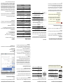
SAFETY PRECAUTIONS
MBRG-300 Modbus Router/Gateway
Quick start reference guide
This document is a reference guide only and must be used
in conjunction with the MBRG-300 User manual.
INTRODUCTION
ELECTRICAL HAZARD
Package Contents
• This equipment must be installed and serviced only by
qualified personnel. Such work should be performed only
after reading the MBRG-300 User manual in its entirety.
• Before performing visual inspections, tests, or
maintenance on this equipment, disconnect all sources of
electric power. Assume that all circuits are live until they
have been completely de-energized, tested, and tagged.
Pay particular attention to the design of the power system.
Consider all sources of power, including the possibility of
backfeeding.
• Apply appropriate personal protective equipment and
follow safe electrical practices.
• Turn off all power supplying the equipment in which the
MBRG-300 is to be installed before installing, wiring or
removing the MBRG-300.
• Always use a properly rated voltage sensing device to
confirm that power is off.
• The successful operation of this equipment depends upon
proper handling, installation, and operation. Neglecting
fundamental installation requirements may lead to
personal injury as well as damage to electrical equipment
or other property.
•
•
•
•
Failure to follow these instructions could result in death
or serious injury!
DESCRIPTION
MBRG-300 unit
Quick start reference guide
2-pin terminal block plug
6-pin terminal block plug
TOP VIEW
Documentation and Additional Resources
This Quick start reference guide must be used in conjunction with the
MBRG-300 User manual.
BOTTOM VIEW
The MBRG-300 User manual and supplemental software packages
can be downloaded from the MBRG-300 web site:
http://www.proconx.com/mbrg300
FRONT VIEW
Clear front cover
Serial port 1 RS-232 connector
Serial port 2 RS-232 connector
Ethernet connector
DIN rail clip
Power LED
Ethernet link LED
Status 1 LED
Status 2 LED
Power terminals
Serial port 1 and 2 RS-485 or serial port 1 RS-422 terminals
Quick start checklist
• Obtain a copy of the MBRG-300 User manual and read it properly
and in its entirety.
• Mount the unit.
• Connect the power. Do not connect yet serial ports.
• Configure the Ethernet communications settings with a web browser
(using an Ethernet crossover cable) or with a terminal program like
HyperTerminal (using a null modem cable)
• Configure the serial line communication settings.
• Configure the operational aspects of the device.
• Wire serial line interfaces.
IGMBRG300-1101
DIN rail mounting and removal
Regulatory notes
1. The MBRG-300 is suitable for use in non-hazardous
locations only.
2. The MBRG-300 is not authorized for use in life support
devices or systems.
3. Wiring and installation must be in accordance with
applicable electrical codes in accordance with the authority
having jurisdiction.
4. This is a Class A device and intended for commercial or
industrial use. This equipment may cause radio interference
if used in a residential area; in this case it is the operator’s
responsibility to take appropriate measures.
5. The precondition for compliance with EMC limit values
is strict adherence to the guidelines specified in the
MBRG-300 User manual. This applies in particular to the
area of grounding and shielding of cables.
To mount the unit on a DIN rail, slot
the top part of the MBRG-300 into
the upper guide of the rail and lower the enclosure until the bottom of
the red hook clicks into place.
1
DIN rail
2
Click
To remove the MBRG-300 from
the DIN rail, use a screw driver
as a lever by inserting it in the
small slot of the red hook and push
the red hook downwards. Then remove the unit from the rail by raising the bottom front edge of the enclosure.
Slide down
2
1
FCC Notice (USA only)
This equipment has been tested and found to comply with the limits
for a Class A digital device, pursuant to Part 15 of the FCC Rules.
These limits are designed to provide reasonable protection against
harmful interference when the equipment is operated in a commercial
environment. This equipment generates, uses, and can radiate radio
frequency energy and, if not installed and used in accordance with
the instruction manual, may cause harmful interference to radio
communications. Operation of this equipment in a residential area is
likely to cause harmful interference in which case the user will be
required to correct the interference at his own expense.
Industry Canada Notice (Canada only)
This Class A digital apparatus complies with Canadian ICES-003.
Mounting rules
•
•
•
•
•
No water splash and water drops
No aggressive gas, steam or liquids
Avoid dusty environments.
Avoid shock or vibration
Do not exceed the specified operational temperatures and
humidity range.
• Mount inside an electrical switchboard or control cabinet.
• Make sure there is sufficient air ventilation and clearance to
other devices mounted next to the unit.
• Observe applicable local regulations like EN60204 /
VDE0113.
Before connecting anything
1. Before installing or removing the unit or any connector,
ensure that the system power and external supplies have
been turned off.
2. Check the system supply voltage with a multimeter for
correct voltage range and polarity.
3. Connect the power supply cable and switch on the system
power. Check if the Power LED is lit.
4. Turn off system power.
5. Connect all I/O cables.
6. Once you are certain that all connections have been made
properly, restore the power.
Power terminals pin assignment
Before connecting power please follow the rules in the section
called “SAFETY PRECAUTIONS” and the section called “Before connecting anything”.
1
V+
V-
INSTALLATION
1
V+ Positive voltage supply (10 - 30 V DC)
2
V-
Negative voltage supply, DC power return
Make sure that the polarity of the supply voltage is correct
before connecting any device to the serial ports! A wrong
polarity can cause high currents on the ground plane
between the V- power supply pin and the serial port ground
pins, which can cause damage to the device.
Pinout as per EIA-574 DTE. Please observe the cabling instructions
decribed in the MBRG-300 User manual!
Please observe the wiring, grounding and shielding instructions
decribed in the MBRG-300 User manual!
RS-232 connector pin assignment
RS-485/RS-422 terminals pin assignment
1
GND
D+
DGND
D+
D-
PORT1 PORT2
RS-485
1
GND
TX+
TXGND
RX+
RX-
RS-422
D- port 1
5
D+ port 1
4
GND
3
RS-485
Pin
D+ port 2
7
GND
6
8
D- port 2
RS-422 Description
GND
TX+
TXGND
RX+
RX-
Modbus Common
Modbus D1 or TXD1
Modbus D0 or TXD0
CD
RXD
TDX
DTR
GND
1
6
DSR
RTS
CTS
RI
Modbus Common
Modbus D1 or RXD1
Modbus D0 or RXD0
DSR (unused)
6
GND Signal ground
5
DTR (unused)
4
TXD Transmit data
3
RXD Receive data
2
DCD (unused)
1
CTS (unused)
8
RTS (unused)
7
9
Do not connect the cable shield to the GND pins! Use an
external chassis ground connection to terminate the shield.
RI
(unused)
in
in
out
out
in
out
in
in
Ethernet & IP configuration
Before configuring the MBRG-300, obtain a unique static IP address,
subnet mask, and default gateway address from your network
administrator.
Use a web browser or a terminal program like HyperTerminal to
configure the MBRG-300’s TCP/IP settings with this information.
IP setup using a terminal program like HyperTerminal
Please consult the MBRG-300 User manual for further details on this
method.
Configuring and commissioning
The configuration pages are accessed using the integrated web server:
The factory default IP address of the MBRG-300 is 169.254.0.10 which
is in the Automatic Private IP Addressing (APIPA) address range.
In order to connect to the MBRG-300 via TCP/IP, your PC must be on
same IP subnet as the gateway.
IP setup using a web browser
1. Disconnect your PC from your corporate network. If your computer
is configured for DHCP it should now automatically fall back to use
a default IP address from the APIPA range 169.254.x.x (Windows
PCs only). If your computer is configured with a static IP address or
does not support APIPA, it must be changed manually to be part of
the 169.254.0.0/16 subnet, for example to 169.254.0.1.
2. Connect an Ethernet crossover cable from the MBRG-300 to the
computer.
3. Start Internet Explorer.
4. In the address box, type 169.254.0.10 and then press Enter.
5. Click Configuration… and then Ethernet & IP in the menu
on the left side of the page.
6. Enter the IP address, subnet mask, and gateway address assigned
to your MBRG-300, then click Save.
MAINTENANCE AND TROUBLESHOOTING
Maintenance
The MBRG-300 does not require maintenance, nor does it contain any
user-serviceable parts. If the MBRG-300 requires service, contact us
directly for assistance.
Refer to the technical support contacts provided at the end of this
document.
Do not open the MBRG-300 enclosure; this will void the product
warranty.
LED indicators
A LED test is exercised at power-up, cycling each LED off, green and
then red for approximately 0.25 seconds. At the same time the poweron self test of the device is performed.
The following table outlines the indicator condition and the
corresponding status after the power-on self test has been completed:
LED
Function Condition
Power Power
Off
Power supply OK
No Ethernet link
Ethernet link OK
Off
Status1
Device
status
Status2
Indication
No power applied to the device.
Green
Ethernet Off
link
Green
Link
Diagnostics and troubleshooting
ELECTRICAL HAZARD
• This equipment must be installed and serviced only by
qualified personnel.
• Qualified
persons
performing
diagnostics
or
troubleshooting that require electrical conductors to be
energized must comply with and follow safe electrical work
practices.
Failure to follow these instructions could result in death
or serious injury!
The device has an unrecoverable fault; may
need replacing.
Device operational but needs commissionFlashing green
ing due to configuration missing, incomplete
1 s rate
or incorrect.
The device has an unrecoverable fault; may
need replacing. Flashing sequence and rate
of Status2 LED indicates fault class.
Red
Device operational but has a fault listed
which requires acknowledgment.
Flashing red
1 s rate
The device is operating in normal condition.
Green
Commu- Off
nication
Green
status
Gateway IP address
Main menu
Configuration sub-menu
Information area
This product is designed and manufactured by:
Power supply
CONTACT
SPECIFICATIONS
Please consult the MBRG-300 User Manual for further details how to
set-up the MBRG-300.
7. Reconnect your computer to your corporate network. If you
assigned a static IP address to your computer in step 1, you must
restore your computer’s original settings before reconnecting to
your network.
750 mW
Intrinsic consumption
30 mA typical @ 24 V DC
Current
10-30 V DC
Voltage
Electromagnetic compatibility
EN 61000-4-2
Electrostatic discharge
EN 55024
Immunity
AS/NZS CISPR 22 / EN 55022 (Class A)
Emissions
EN 61000-4-6
Conducted RF
EN 61000-4-4
Fast transients
EN 61000-4-3
Radiated RF
Enclosure
Convection
Cooling
IP 20 / NEMA Type 1
Classification / Type rating
35 mm DIN rail (EN 60715)
Mounting
Self-extinguishing PC/ABS blend (UL 94-V0)
Material
proconX Pty Ltd
Unit 7, 14 Argon St, Sumner QLD 4074, Australia
Tel +61-7-3376 3911 Fax +61-7-3102 9206
Email: [email protected]
Website: http://www.proconx.com
Technical Support
We provide an electronic support and feedback system for our proconX
products. It can be accessed through the following web link:
http://www.proconx.com/support
Product Returns
Before returning any product for service, repair or warranty, obtain first
a RMA (Returned Material Authorization) number by contacting our
technical support.
Environmental
No Modbus/TCP connection.
Free from corrosive gas, minimal dust
Operating ambience
10 to 95% relative humidity, non condensing
Humidity rating
-25 to 85 °C / -13 to 185 °F
Storage temperature
0 to 60 °C / 32 to 140 °F
Operating temperature
Physical
Modbus/TCP connection established.
The status web pages served by the MBRG-300, display diagnostic
data that may be helpful in troubleshooting communication problems.
0.12 kg / 0.265 lb
Weight
101 x 22.5 x 120 mm / 3.98 x 0.886 x 4.72 in
Dimensions
Compliance
In addition the About page contains information about your specific
MBRG-300, including the serial number and media access control
(MAC) address. Some of these pages show a Clear Counter
button. Clicking this button clears all cumulative readings shown on this
particular page. If power to the MBRG-300 is lost, all values reset to
zero.
ICES-003 (Class A)
Canada
FCC Part 15 (Class A)
USA
CE, RoHS
Europe
C-Tick
Australia
Specifications subject to change without notice.
proconX is a trademark of proconX Pty Ltd. Modbus is a registered trademark of
Schneider Automation Inc. All other trademarks and logos are property of their
respective owners.
Copyright © 2011 proconX Pty Ltd. All rights reserved.
proconX Pty Ltd makes no warranty for the use of its products, other than those
expressly contained in the Company’s standard warranty which is detailed in
the Terms and Conditions located on the Company’s Website. The Company
assumes no responsibility for any errors which may appear in this document,
reserves the right to change devices or specifications detailed herein at any time
without notice, and does not make any commitment to update the information
contained herein. No licenses to patents or other intellectual property of proconX
are granted by the Company in connection with the sale of proconX products,
expressly or by implication. proconX products are not authorized for use as
critical components in life support devices or systems.