1
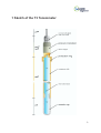
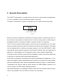
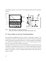
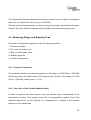
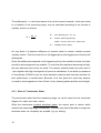
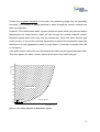
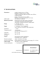
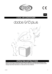
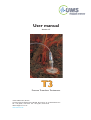
User manual
Version 1.7
T3
Pressure Transducer Tensiometer
©2002 UMS GmbH, Munich
Umweltanalytische Mess-Systeme GmbH · Gmunderstr. 37 · D-81379 Muenchen
Tel.: +49 (0) 89 / 12 66 52-0 · Fax: +49 (0) 89 / 12 66 52-20
eMail: [email protected]
www.ums-muc.de
Index
1
Sketch of the "T3" Tensiometer
3
2
2.1
2.1.1
2.1.2
General Description
Tensiometer Construction
Sensor Cap
Tensiometer Shaft
4
5
5
6
3
3.1
7
3.2
3.3
3.4
3.5
3.6
3.6.1
3.7
General Instructions
How to Connect your Tensiometer
to a Display Unit or a Data-Logging-System
Installation
How to Remove
How to Check the Filling Level, refill on site
Refilling the Tensiometer
Calibration
Checking the zero offset
Maintenance and Storage
7
8
9
10
10
11
11
12
4
4.1
4.2
4.3
4.3.1
4.3.2
4.3.3
4.3.4
4.3.5
Tensiometric Principle and Limits
Theory of Water as Measuring Variable
Theory of Water as Pressure Transmitting Medium
Measuring Range and Standing Time
Pressure Transducer
Pore Size of the Ceramic Material Used
State of the Tensiometer Water
Ambient Pressure
Ambient Temperature
13
13
14
15
15
15
16
18
18
5
Technical Data
19
2
1 Sketch of the T3 Tensiometer
3
2 General Description
The UMS T3 tensiometer is a probe that can be used in a wide variety of applications.
It is very compatible, safe and extremely simple in handling.
The type of tensiometer is shown on the label (not for newer versions with plug):
T3-30
type
length of shaft
[ cm ]
Electronic pressure transducer tensiometers are high resolution measuring devices for
the continuous measurement of water tension in the soil, being used in a wide range of
hydrological studies, soil physical studies or general studies of ecosystems.
The T3 is used to measure water tension in the soil in the non saturated zone. The water
tension is measured and converted into a defined continuous electrical signal. This signal
can be displayed with a voltmeter and power supply or with the UMS Infield 5, which
transmits the electric signal in pressure unit hPa (hecto Pascal). Also, the signal can be
adapted to a data logging unit for logging the water tension signals automatically.
The water tension is a direct measure of the availability of water in the soil for plants and
is therefore an important plant physiological parameter.
In the field of ecosystems, tensiometers are used for hydrological investigations, e. g. for
input and transport studies, gravitational water studies or to measure the water tension
itself as a characteristic value, used in mathematical models of energy - or water balance.
Tensiometers can also be used as control sensors for UMS-irrigation systems or as
control sensors for UMS suction sampling systems.
Care should be taken in correlating the water tension with the volumetric water content.
This is only possible if the soil texture is known very accurately.
4
2.1 Tensiometer Construction
2.1.1 Sensor Head
The sensor head consists of the pressure transducer, which is connected to a test, supplyand pressure reference lead, the silicon cone, a protective cap and the type plate. The
sensor principle is based on the “piezoresistive effect” of silicon semiconductors, which
change their specific electric resistance on deformation, and are processed to a defined
signal via a Wheatstone bridge. The deformation is caused by the pressure (or water
tension) on the silicon chip, which is very thin and therefore extremely sensitive to
pressure variations.
The pressure transducer is calibrated for 10.6 Vdc, and so requires a 10.6 Vdc regulated
power supply such as the TV-BATT. The signal changes in direct proportion to the power
supply. At 10.6 Vdc we obtain a signal of 0 hPa ≈ 0 mVdc and 1000 hPa ≈ 103 mVdc.
The tolerance is ± 3 mV, depending on the pressure transducer.
The exact calibration values are shown in the UMS Calibration Certificate supplied with
each tensiometer. This is not necessary for tensiometers supplied with Infield-systems.
Since 2001 the signals of all Tensiometers are balanced by potentiometers inside
the pressure senor head!
Since the water tension is measured with respect to the atmospheric air pressure, this
pressure is transferred to the referece port of the pressure transducer inside the body
through the (white) membrane on the cable. This membrane must always have contact
to the atmospheric pressure.
After the tensiometer is filled, the sensor cap is placed on the shaft using the silicon cone.
The protective cap also contains a pull protection for the cable. However, force should
be avoided. (Secure the cable to the tensiometer shaft so that no one can trip over it.)
Although the protective cap reflects the greater part of the sunlight striking it, direct
exposure to the sun should be avoided (Temperature drift). The sensor surface is
electrical isolated to prevent influence of galvanic soil potentials.
5
2.1.2 Tensiometer Shaft
The tensiometer shaft consists of the ceramic cup (also tensiometer cup), the acryl glass
shaft and the excess pressure protector.
The tenisometer ceramic acts like a porous filter. Firstly, it is water-permeable, so that
the water tension of the soil can be transmitted to the tensiometer water and, via this,
to the pressure transducer. Secondly, when wet it is impermeable to air below a certain
pressure, so that a “water tension” (under-pressure) can build up in the tensiometer
shaft. Every ceramic is selected by UMS for a defined pore size and homogeneous pore
structure.
The tensiometer water must be degased and deionized, so it will transmit differing
pressures hydraulically to the pressure transducer largely without changed volume.
Gases which are dissolved at atmospheric presseure will become gasiform with rising
water tension.
If the soil dries out, the tensiometer water vaporises at a pressure of about 900 hPa,
expands, and "runs" out of the cap. If the soil dries out further, the water film in the pores
of the ceramic disintegrates, allowing air to enter. When this happens, a refill of the
tensiometer is necessary.
At the upper end of the shaft, two diametrically opposed holes are drilled. A silicone
rubber ring is stretched over them. This allows excess pressure built up through too rapid
placement of the sensor cap on the shaft to be released through these holes (excess
water can escape). The pressure sensor is thus protected from excess pressure.
6
3 General Instructions
3.1 How to Connect Your Tensiometer
to a Display Unit or a Data-Logging-System
The pressure transducer works as an asymmetric Wheatstone full bridge.
Tensiometers with plug (new version since 2001) that have a black cable and the
4-pin plug M12/IP67 have the following configuration:
Tensiometers without plug and the grey cable have this configuration:
- brown wire is power supply minus, white wire is power supply plus
- yellow wire is signal minus, green wire is signal plus
Note: Do not connect the signal minus to the power supply minus input of your measuring unit!
The signal minus is not '0V' or 'Ground' when the Tensiometer is supplied with -5V/+5.6V,
because then the signal range is between +3.2 V and 6.8 V with reference to power supply.
As the pressure transducer is a Wheatstone full bridge, it has to be connected in a certain
mode. Please read therefore the manual of your display unit or data-logging-system
before connection.
7
3.2 Installation
Please note that the water column inside the shaft causes an hydrostatic pressure on
the pressure sensor and has to be compensated. The water column is the shaft length
plus 3 cm for the cup! Withdraw 1 hPa for each cm of water column from the reading:
Correct soil water tension [hPa] = measured reading [hPa] - water column [cm]
Find the correction value depending on the resp. shaft lenght on the calibration certificate!
Example for 30 cm shaft, reading 130 hPa: Correct tension = 130 hPa - 33 cm = 97 hPa
The tensiometer has an outer diameter of 20 mm. An appropriately large drilling rod
(UMS accessory) must be selected.
- drill a hole of the required depth at the drilling location.
- In stony soil, it may be necessary to drill the hole several times. Should the walls of
the hole fail to hold, UMS lining tubes can be used.
- Pour a thin paste of quartz clay powder and water into the hole. For loamy soil, use
ca. 20 ml plus ca. 100 ml of water; for coarse, clay-like soil ca. 30 ml; for sandy soil
ca. 100 ml and for stony soil adjust the proportions according to the stone content.
- Now remove the plastic container from the tensiometer cup, turning the container
slowly (clockwise when viewed from below).
Immediately insert the tensiometer in the hole in the soil.
8
Filling the T3
3.3 How to Remove
If the tensiometer is to be removed from the soil, you will need the following equipment:
1. The plastic bottle (protective container for the ceramic cap) with ca. 10 ml of
deionised water.
2. A five liter container of water (tap water).
3. Adhesive tape and a water-proof marker.
4. For each tensiometer, a rod approximately 20 mm in diameter and of a length
sufficient to allow the tensiometer to be reinserted at the same location later. The rod
should be rounded at the end. (The shape of the tensiometer cup is ideal.)
Procedure:
Hold the tensiometer by its shaft and pull it vertically out of the soil, avoiding sideways
movements. After removal, place the plastic bottle, half-filled with water, over the ceramic
cup, rotating it slightly clockwise. Push the rod into the hole in the soil with a slight turning
motion. Mark the rod with the tensiometer number. If the tensiometer is connected to a
logger, the signal channel should also be noted on the end of the cable.
Please note!
The tensiometer should not be rotated when inserted and removed. If it is
removed after a dry period and the tensiometer is stuck, water poured along the shaft
works wonders. Should the tensiometer remain immovable, pull it out by turning screw
up, using as little force as possible.
9
3.4 How to Check the Filling Level, refill on site
In order to accertain that the tensiometer is still properly filled, check that there is an air
bubble in the shaft directly beneath the sensor cap. This bubble should always be as
small as possible, or better not be present. If it is longer than 2 cm, pull off the sensor
cap and refill the shaft to the top with deionized water. Then replace the sensor cap.
3.5 Refilling the Tensiometer
Place the tensiometer in a vessel with deionized water. The ceramic cap must be
immersed to a depth of at least 20 cm. The shaft itself is not filled with water, since this
would lead to air being trapped within the walls of the ceramic cap. Wait about 30 minutes
until the water meniscus can be seen in the tensiometer shaft above the ceramic cap.
Now empty the shaft and fill the tensiometer shaft to the top with deionized water.
Place the sensor cap on the shaft with a slight rotational motion and connect the
tensiometer to your display device. Wrap a damp cloth around the sensor cap (simulating
dry soil). A water tension of 850 hPa should be attainable (minus the shaft length - e.g.
for a shaft of 30 cm => 850 - 30 = 820 hPa). The shaft must be held vertically with the
sensor cap pointing downwards.
In case bubbles appear inside the shaft wall, these can be caused to rise by gently
tapping sideways. Then remove the sensor cap again in order to refill the shaft to the top.
If the sensor cap is now replaced, the water tension should increase rapidly if a dry cloth
is wrapped around the ceramic cap. Wrap the ceramic cap in a damp cloth or place it
in a water-filled vessel so that at least the ceramic cap is covered with water.
Your T3 is now ready for use.
10
3.6 Calibration
The most important thing is to check the zero offset, since this value drifts very much
faster than the gain. The stability (of the zero point) over one year is typically 0.5% of full
scale. To maintain an accuracy of 5 hPa, calibration has to be done annually.
To recalibrate the slope you need the UMS Calibration Kit.
3.6.1 Checking the zero offset
For checking the zero offset, it is not necessary to use the UMS Calibration Kit. This
check can be done much more easily:
shaft
Place the tensiometer in a beaker
ceramic cup
until the ceramic end is 10 mm below water level.
10 mm
The tensiometer must have previously been filled in the correct way.
After about 5 minutes or less (time depends on the filling level) you should get a constant
value on your display unit or data-logging-system. This value should not vary more than
± 5 hPa from the 0 hPa-value in the calibration certificate.
If it exceeds this, the new value should be written into your calibration certificate with the
calibration date. How to change the zero offset of your display/recording unit should be
shown in the corresponding user manual of your display unit or data logger.
If the slope is also to be calibrated, UMS offers this as a service.
11
3.7 Maintenance and Storage
3.7.1 Cleaning the Tensiometer
Clean the tensiometer with a damp cloth (water) or with petroleum ether: Do not use acid
or solvent, as they could attack the adhesive joint or the material itself.
3.7.2 Storage
Place the tensiometer as near to the vertical as possible in a pail of water so that the
ceramic cap cannot dry out. To prevent the formation of algae, the tensiometer should
be stored in a dark place. In case of storage for longer than 3 months, the T3 can also
be stored dry. Filled tensiometers always must be protected from freezing!
12
4 Tensiometric Principle and Limits
4.1 Theory of Water as Measuring Variable
Water tension measurement (absorptive tension measurement) as a direct means for the
measurement of water available in soils for plants involves the measurement of total
potential of water retention in the soil under investigation (excluding osmotic potential,
potentials of differential pressure and gravitation).
The saturation state of soil (level of ground water, resp.) determines the extent of water
absorption with regard to the water tension in soil through the ceramic material by the
tensiometer which is otherwise hermetically sealed. The porous properties of the ceramic
material (sintered Al2O3) are considered ideal.
The atmospheric underpressure built up in the tensiometer (assuming the above mentioned potentials are neglected) minus the pressure accounted for by the vertical length
of the tensiometer is equivalent to the water tension in the soil under investigation. (The
water column in the tensiometer leads to a hydrostatic potential p acting upon the
pressure receptor due to its "hanging weight", and should be added to the measured
value according to the equation as follows:
p = density x g x h
(1 Pa (Pascal)= 1 N/m2)
This potential, however, has been compensated by calibration.
Example:
Vertical difference between pressure receptor (h1) and ceramic tip (h2) = 10 cm,
p = 1000 kg/m3 x 9.81 m/s2 x 0.1 m
= 981 kg/ms2
(1 N = kg·m/s2)
= 981 N/m2
(1 hPa (Hektopascal) = 100 N/m2)
p = 9.81 hPa
13
The following schematic view informs of the measuring principle and the hydrostatic
relations:
water tension
cmWS
5
10
5
10
4,2
10
pF
7
5
PWP
4,2
coarse
clay
sand
3
10
clay
water
available
for plants
3
300
2,5
60
1,8
10
1
∆h
∆h
FK
1
0
∆p
water
not available
for plants
20
60
40
water content [Vol%]
water level
figure 1: Measuring Principles and Hydrostatic Relations
(taken from: Lehrbuch der Bodenkunde, Scheffer/Schachtschabel 1981)
4.2 Theory of Water as Pressure Transmitting Medium
Since deionised and degassed water with a modulus of compression of approx. 1 can
be regarded as an ideal non-compressible liquid, it is useful as a pressure transmitting
medium in the range of atmospheric pressure p0 (= 0 hPa) to atmospheric underpressure
p1 (= 950 hPa) in a temperature range of > 0 °C to < 30 °C without change of volume
(see curve of the water vapour pressure relationship).
This means that the tensiometer with its mechanical tightness in the said pressure range
exchanges a very limited amount of water via the ceramic material during the process
occuring when pressure is transfered from the ceramic tip to the pressure transducer
(sensor). This applies to the use of relatively rigid material like acrylic glass and the
pressure receptor.
14
The tensiometer has been designed so that only a small amount of water is exchanged
when the soil cycles from wet to dry (0 to 850 hPa).
This ensures that the tensiometer can last for many drying cycles, provided that the water
inside is free from dissolved gasses and all bubbles (including microscopic ones).
4.3 Measuring Range and Standing Time
The extent of measuring depends on the following parameters:
1. Pressure receptor
2. Pore size of ceramic cup
3. State of tensiometer water
4. Ambient pressure
5. Ambient temperature
4.3.1 Pressure Transducer
The pressure transducer can tolerate pressures in the range of + 3000 hPa to - 3000 hPa
(theoretical value) non-destructively and measure them linearly in the range of +1000
hPa to -1000 hPa (linearity error < 0.1%).
4.3.2 Pore Size of the Ceramic Material Used
In order to measure soil water tension, a porous ceramic cup is incorporated for the
transmission of water. The ceramic, when wet, is impermeable to gases. This is the
essential requirement for the build-up of a underpressure in relation to the ambient
pressure in the tensiometer.
15
The bubble point - i.e. the first entrance of air into the ceramic material - which also leads
to a limitation of the measuring range, may be calculated according to the formula of
capillary tension as follows:
40 · σ
K =
D
D=
Pore diameter [µm, 10-6 m]
σ = Surface tension [dynes/cm]
(water: 0°C:75.6; 20°C:72.7; 50°C:67.8)
K=
Capillary tension [hPa]
Air may burst in if pressure difference of ceramic inside to ceramic outside exceeds
capillary tension. Then the water film in the biggest pores (the biggest pore channel) will
disintegrate.
Since the bubble point depends on the largest pore line from outside to inside, the latter
should be as homogeneous as possible. To avoid the flow resistance becoming too high,
the pore diameter must not be too small. The ceramic material used has a pore size of
1 µm together with high homogeneity of pore size distribution. It can block up pressures
of theoretically 3000 hPa (only for water-satuated ceramics) and therefore provides for
best performance in tensiometers. Because of its fine pores the shaft may become
covered by microorganisms in time. Rinse it in dry cleaning spirits carefully and at length.
4.3.3 State of Tensiometer Water
The tensiometer water limits the measuring range, as can be seen from the two-phase
diagram for water and water vapour.
When the tensiometer contains dissolved gases, the vapour point is raised, which
restricts the measuring range considerably. Therefore care should be taken to degas the
deionised water as completely as possible (e.g. by boiling).
16
If there are no gases dissolved in the water, the measuring range may be repeatedly
traversed. (The diffusion of gases dissolved in water through the ceramic material may
then be neglected.)
However, if the tensiometer water contains dissolved gases which get gaseous before
reaching the soil water tension, water will flow through the ceramic material outside.
Dissolved gases pass once more into the tensiometer, when soil water tension gets
nearer to zero. In view of the resulting exponential conditions the tensiometer water has
therefore to be well degassed to obtain a long lifetime (= time that is needed until refill
is necessary).
If the water tension values are low, the tensiometer water may be regenerated less often.
pressure p [hPa]
This also applies for water tension values which show only small changes.
1000
900
800
700
600
500
liquid phase
400
300
200
100
vapour phase
vacuum
31,2
0
0
10
20
30
40
50
60
70
80
90
100
temperature t [˚C]
figure 2: Two-Phase Diagram of Water/Water Vapour
17
4.3.4 Ambient Pressure
The maximum measuring value depends directly on the ambient pressure.
4.3.5 Ambient Temperature
The maximum measuring value depends on the vapour point of water which itself is
temperature dependent, and therefore also depends on the ambient temperature (see
vapour point curve exemplified).
We wish you the best success in measuring.
Do not hesitate to contact us for further questions.
18
5 Technical Data
Dimensions
Length of ceramic cap: ca. 50 mm
Diameter of ceramic cap: ca. 20 mm
Length of tensiometer shaft: as desired, max. 200 cm,
material acrylglas
Height of the sensor cap: ca. 40 mm
Diameter of the sensor cap below: ca. 14 mm
Cable length
5 m standard, as desired
Measuring principle
Measuring the soil water tension, transmitted
via ceramic cup onto the tensiometer water
and pressure transducer giving an analog signal
Range
0 - 850 hPa = pF 2.9
minus shaft length (1cm ≈ 1 hPa)
Signal
0 - 100 mVdc ± 3 mV, calibrated
exact values are recorded for each tensiometer
Impedance
≈ 2.6 kΩ
Temperature shift
compensated,
typ. drift: 0.5% FS above 25 °C
Hysteresis
typ. 0.1% FS
Stability over
one year
typ. 0.5% FS
Sensor
piezoresistive pressure transducer,
overpressure max. ± 3000 hPa
Electronic principal
assym. wheatstone full bridge
Common mode range
signal distance to mass with 10,6 Vdc supply: 2.8 - 6.8 Vdc
Power supply
10.6 Vdc (5-15 Vdc), stabilisized
Current consumption
≈ 1.3 mA (with 10.6 Vdc)
Umweltanalytische
Mess-Systeme GmbH
All rights reserved
© 2001 UMS GmbH, München.
Gmunderstraße 37
D - 81379 München
Tel.: ++ 49 (0) 89 / 12 66 52 - 0
Fax : ++ 49 (0) 89 / 12 66 52 - 20
eMail: [email protected]
www.ums-muc.de
19