1
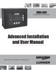
OWN-ADV
WaveNet Digital Monitoring System
Advanced Installation
and User Manual
Marine Generators | Marine Diesel Engines | Land-Based Generators
Northern Lights
USER MANUAL
for WaveNet Generator Set Controllers
Table of Contents
35
35 - 37
38
38
39
39
40
40
40
41
GROUP 6 - RECOMMENDED MAINTENANCE.. 41
GROUP 7 - WAVENET REMOTE PANEL
42
42
42
42 - 43
43
43
44
GROUP 8 - APPENDIX A: ACCESSORY LIST
45
45
46
46
47
GROUP 9 - APPENDIX B: MODBUS MAP
47 - 48
49
49 -65
GROUP 10 - APPENDIX C: NMEA 2000 PGN’S 62
63 -67
67
67
67
67
68
68
68
68
GROUP 11 - APPENDIX D: ADDITIONAL DRAWINGS.69
2
GROUP 1 - WAVENET CONTROLLER SERIES
3
GROUP 2-RECEIVING, HANDLING & STORAGE .3-4
GROUP 3 - INSTALLATION & WIRING
4-5
5
5
5
5 - 10
10
GROUP 4 - OPERATION & BASIC USER CONFIGURATION
11
11
11
12 - 13
13
13 - 14
14
14
15
15
15 - 16
16 - 17
17 - 19
20
20 - 21
21 - 22
22
GROUP 5 - ADVANCED SETUP ............. 22 - 27
28 - 29
29
29 - 30
30
31
31
31
31 - 32
32 - 33
33
34
34
35
Proprietary Information
1
WAVENET SPECIFICATIONS
Table 1: WaveNet Speci cations
2
1. WAVENET CONTROLLER SERIES
1.1 THIS MANUAL
2. RECEIVING, HANDLING & STORAGE
Receiving:
3
2. RECEIVING, HANDLING & STORAGE (CONT’D)
Handling:
Storage:
3. WAVENET SERIES INSTALLATION AND WIRING
3.1 SAFETY INFORMATION
Caution:
Danger:
Danger - High Voltage:
4
3.1 SAFETY INFORMATION (CONT’D)
NEVER
3.2 WAVENET 12/24VDC SYSTEM OPERATION
3.2.1 RELAYS
3.2.2 RELAY FUSES
CAUTION:
3.3 WAVENET TERMINALS
The wire gauges given in the table are the minimum recommended only.
5
Figure 1 - General WaveNet System Wiring Diagram
6
Figure 2 - Digital IO Example
7
TABLE 2
8
TABLE 2 (CONTINUED)
These are sinking outputs (i.e. switched to ground)
9
TABLE 2 (CONTINUED)
DO NOT CONNECT TOGETHER.
3.3.1 CURRENT TRANSFORMER (CT) WIRING NOTE
Do not tie the negative leads together to a common ...
neutral or ground.
10
4 WAVENET OPERATION & BASIC USER CONFIGURATION
4.1 POWER-UP
4.2 CONTROLLER ALARMING
emergency stop input
4.3 EMERGENCY STOP
emergency stop
11
4.4 CONTROLLER STATES
12
4.4 CONTROLLER STATES (CONT’D)
4.4.1 LOCKING THE WAVENET SCREEN WHILE IN RUN MODE
4.5 WAVENET START / STOP BEHAVIOR
13
4.5 WAVENET START / STOP BEHAVIOR (CONT’D)
Stopping the Generator
Preventing a Stop when in Cool Down
4.6 GENERATOR STARTING AND STOPPING
4.7 CONTROLLER SLEEP
14
4.8 WAVENET MENU SYSTEM OPERATION
4.9 BASIC MENU
4.9.1 CLOCK SETUP
15
4.9.1 CLOCK SETUP (CONT’D)
4.9.2 BASIC SETUP
Contrast Adjustment
Page Roll Delay
The State Roll Delay
Setting the State Roll Delay to a larger value may cause some warning or event
messages to not be displayed if the event or warning is of a short duration.
Sleep Delay
Not In Auto
OFF Mode Start
16
4.9.2 BASIC SETUP (CONT’D)
4.9.3 EVENT HISTORY LOG
17
EVENT LOG ENTRIES
18
EVENT LOG ENTRIES (CONTINUED)
19
4.10 WAVENET LED STATUS INDICATORS
4.11 LAMP INDICATION MEANINGS
20
4.11 LAMP INDICATION MEANINGS (CONT’D)
4.12 WARNINGS AND FAILURES
warning
21
4.12 WARNINGS AND FAILURES (CONT’D)
failure
Low Coolant Level
Low Fuel Level and
4.13 GENSET ONLINE
“Genset Online”
5. ADVANCED SETUP
22
ADVANCED MENU LAYOUT SUMMARY
Analog Inputs:
23
TABLE 9: SUBMENUS OF THE ADVANCED MENU
24
TABLE 9: SUBMENUS OF THE ADVANCED MENU
25
TABLE 9: SUBMENUS OF THE ADVANCED MENU
26
TABLE 9: SUBMENUS OF THE ADVANCED MENU
Failures:
Warnings:
Events:
27
5.1 ANALOG INPUTS
Attaching Switches to the Sender Inputs
Input Pin Disable Note
28
5.1 ANALOG INPUTS (CONT’D)
5.1.1 FUEL LEVEL SENDER - SPECIAL CASE
Resistance = (Voltage Output x Pull-up Resistance) / (5 – Voltage Output)
5.1.2 WAVENET SENDER SUPPORT
Signal Source
29
5.1.2 WAVENET SENDER SUPPORT (CONT’D)
5.2 SPEED SENSING
30
5.2.1 RATED SPEED
Rated frequency = (Number of teeth x Rated Speed) / 60
5.3 GENERATOR (AC VOLTAGE / CURRENT / FREQUENCY) SETUP
5.3.1 AC FREQUENCY
5.3.2 AC VOLTAGE
31
5.3.2 AC VOLTAGE (CONT’D)
5.3.2.1 VOLTAGE SELECT INPUTS
32
5.3.2.1 VOLTAGE SELECT INPUTS (CONT’D)
5.3.3 AC CURRENT
“Turns Ratio”
The WaveNet current terminals can handle a maximum of 5A. Larger currents can
damage the WaveNet.
Hi Wye Current
Cur Warn Latch
Do not tie the negative leads together to a common
neutral.
33
5.4 ENGINE LOGIC
Crank Disconnect
Crank Oil Pressure
5.4.1 STARTUP SEQUENCE
Delay To Start
Preheat (glow plug)
Crank Time
Crank Disconnect Setting
Crank Rest
Time
“Fuel On During Crank Reset”
THE LCD WILL TURN OFF DURING THE FIRST 2 SECONDS OF CRANKING TO LIMIT
THE VOLTAGE DIP DURING CRANKING.
Midheat Time
Crank Attempts
over crank failure
Restart on False Start
Warm-Up
PostHeat
34
5.4.1.1 LOCKED ROTOR
Crank Oil Pressure
Crank Oil Pressure
5.4.2 SHUTDOWN SEQUENCE
Cool-down
ETS On Duration
5.5 DIGITAL OUTPUT SETUP
Section
5.4.1
Section 5.4.2
Section 5.4.1
section 5.4.2
section 5.4.1
35
5.5 DIGITAL OUTPUT SETUP
section 5.1
section 5.1
section 5.1
section 5.6
section 5.1
section 5.2
section 5.2
section 5.2
section 5.2
section 5.1
section 5.1
section 5.7
section 5.7
section 5.6
Section 4.4
Section 5.4.1
Section 4.4
Section 5.4.1
(Section 5.3.2)
36
5.5 DIGITAL OUTPUT SETUP (CONT’D)
(Section 5.3.2)
(Section 5.3.3).
section 5.1
(section 5.1
section 4.4
Table 13 in section 5.6
section 5.9
section 5.11
section 5.11
section 5.12
Table 13 on page 38
Section 5.3.2 on page 31
37
5.6 DIGITAL INPUT SETUP
5.7 BATTERY SETUP
warning
Low Vol InCrank
38
failure
5.8 PASSWORD SETUP
The default password is all zeros.
This will reset ALL
settings to their factory default so make sure to record
the controller settings before doing this.
5.9 SET MAINTAIN
count interval
reset counter
39
5.10 SET MODBUS
5.11 COMMON FAULTS
Common Fault 1
Common Fault 2
Common Fault Output 1
Common Fault Output 2
5.12 SET DUMMY LOAD
Load On Point
Load Off Point
40
5.13 NMEA 2000 SETUP
Engine Instance
Stop Con rmation Disable/Enable
NMEA2000 Address Claiming:
6 RECOMMENDED MAINTENANCE
WARNING
41
7 WAVENET REMOTE PANEL
7.1 ON-LINE GENSET STATUS MODE
Genset
Controller’s Name State
Status Mark
7.1.1 GENSET CONTROLLER’S NAME
7.1.2 STATE
AUTO RUN FAIL OFF
AUTO
42
MENU.
7.1.2 STATE (CONT’D)
RUN
FAIL
OFF
MENU -
7.1.3 STATUS MARK
7.2 ON-LINE GENSET PARAMETER MODE
AUTO
RUN
FAIL
43
7.3 REMOTE UNIT SETTINGS
Setup
Clock Setup Basic
Advanced Setup
Clock Setup
Basic Setup
Advanced Setup
44
8 APPENDIX A: ACCESSORY LIST
8.1 WAVENET CONTROLLER HARNESS - ACCESSORIES
8.2 WAVENET PROGRAMMER
45
8.3 CT’S (CURRENT TRANSFORMERS)
Figure 6 - AC Current sensing connections
8.4 WAVENET REPLACEABLE 12/24VDC RELAYS
46
8.5 WAVENET FUSING
9 APPENDIX B: MODBUS MAP
9.1 COMMUNICATION DETAILS
47
9.1 COMMUNICATION DETAILS (CONT’D)
Device Address Field
Function Code Field
Data Block Field
Error Check Field
Serial Transmission Details
48
9.2 MODBUS COMMANDS
start address = register address – 40 000.
9.3 REGISTER MAP
NOTE: All parameters are assumed to be unsigned integer values unless otherwise speci ed in the “Range” column.
1st Generation ModBus Support
49
9.3 REGISTER MAP (CONT’D)
50
9.3 REGISTER MAP (CONT’D)
51
9.3 REGISTER MAP (CONT’D)
52
9.3 REGISTER MAP (CONT’D)
53
9.3 REGISTER MAP (CONT’D)
CAUTION – when
received in the Running mode the controller immediately goes to the OFF mode (no
cool-down is performed). When received in
failure mode this will reset the system failure
and revert to the OFF mode.
The register is read only in the
OFF mode of operation and ignored in all
other operating modes.
When
cool down is enabled and a stop command
is received the controller will proceed to the
cool down mode then shutdown equipment.
When in controller menu/OFF sleep mode if
the controller is required to go to the AUTO
mode a system disable command (40098)
must be written followed by system enable
command (40098).
54
9.3 REGISTER MAP (CONT’D)
55
9.3 REGISTER MAP (CONT’D)
56
9.3 REGISTER MAP (CONT’D)
57
9.3 REGISTER MAP (CONT’D)
4. DIGITAL I/O AND ANALOG INPUTS
Note: Do not read the start/stop digital
input (Bit 8) as a means to determine if start
signal active or not active, please read the
register 40100 for system state.
58
9.3 REGISTER MAP (CONT’D)
Advanced Modbus register support
59
9.3 REGISTER MAP (CONT’D)
60
9.3 REGISTER MAP (CONT’D)
61
9.3 REGISTER MAP (CONT’D)
10: APPENDIX C: NMEA2000 PGN’S
62
10.1 NORTHERN LIGHTS PROPRIETARY (FAST PACKET)
63
10.1 NORTHERN LIGHTS PROPRIETARY (FAST PACKET)
64
10.1 NORTHERN LIGHTS PROPRIETARY (FAST PACKET)
65
10.1 NORTHERN LIGHTS PROPRIETARY (FAST PACKET)
66
10.1 NORTHERN LIGHTS PROPRIETARY (FAST PACKET)
10.2 ADDRESS CLAIM
10.3 ISO 11783 REQUEST
10.4 PRODUCTION INFORMATION
10.5 GENERATOR PHASE A/B/C BASIC AC QUANTITIES
67
10.6 ENGINE PARAMETERS (RAPID UPDATE)
10.7 ENGINE PARAMETERS (DYNAMIC)
10.8 BATTERY STATUS
10.9 FLUID LEVEL
68
69
11 APPENDIX D: ADDITIONAL DRAWINGS
WAVENET INSTALLATION TO SOUND SHIELD
71
WAVENET INSTALLATION TO SOUND SHIELD
72
WAVENET INSTALLATION IN SOUND SHIELD PANEL
73
WAVENET INSTALLATION TO SOUND SHIELD
74
WAVENET INSTALLATION TO SOUND SHIELD
75
WAVENET INSTALLATION TO SOUND SHIELD
76
WAVENET PANEL INSTALLATION: STEP 1
77
WAVENET PANEL INSTALLATION: STEP 2
78
WAVENET INSTALLATION TO SOUND SHIELD
79
WAVENET PANEL INSTALLATION STEP 1
80
WAVENET PANEL INSTALLATION: STEP 2
81
WAVENET INSTALLATION TO SOUND SHIELD
82
WAVENET INSTALLATION TO SOUND SHIELD
83
WAVENET REMOTE PANEL INSTALLATION DIMENSIONS
84
4420 14th Ave. NW., Seattle WA 98107
Tel: (206) 789-3880 • 1-800-762-0165 • Fax: (206) 782-5455
Northern Lights and Lugger are registered trademarks of Northern Lights, Inc.
www.northern-lights.com
© 2012 All rights reserved. Litho USA.