1
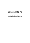
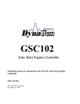
GSC400 Series
Automatic Engine Controller
GSC400 Automatic Engine Controller
Installation and User Manual
Full Version File: GSC400 Rev1.2.doc, April 2006
2
Thank You For Purchasing This DynaGen Product
Please Read Manual Before Installing Unit
Receipt of Shipment and Warranty Return Information
Upon receipt of shipment, carefully remove the unit from the shipping container and
thoroughly examine the unit for shipping damage. In case of damage, immediately
contact the carrier and request that an inspection report be filed prior to contacting
DynaGen.
All returned items are to be shipped prepaid and include a Return Material Authorization
(RMA) number issued by DynaGen. RMA forms are available by contacting DynaGen
Technical Support through the contact methods listed below.
Limited Warranty
DynaGen will repair or replace any GSC400 series engine controller which proves to be
defective under normal and proper use within Three Years from the date of shipment.
This constitutes the only warranty and no other warranty shall be implied.
We welcome your comments and suggestions. Please contact us at:
DynaGen Technologies Inc.
Phone: 1-888-396-2436
(902) 562 0133
Fax: (902) 567 0633
Email: [email protected]
WEB SITE: www.dynagen.ca
User Manual for the GSC400 Series Automatic Engine Controller
3
Table of Contents
GSC400 Series Specifications
4
1.0 GSC400 Product Series
5
2.0 Receiving, Handling, and Storage
2.1 Receiving:
2.2 Handling
2.3 Storage
6
3.0 GSC400 Product Number Identification
7
4.0 GSC400 Series Installation and Wiring
4.1 General information
4.2 Mounting location
4.3 Connector Layout
4.4 Connector Information
4.5 AC Voltage Sensing
4.6 AC Current Sensing
4.7 AC Wiring Diagram
4.8 DC Wiring Diagram
4.9 Analog Input Wiring Diagram
4.10 Digital Input wiring Diagram
4.11 Connector Details
8
5.0 GSC400 Modes of Operation
5.1 Off mode
5.2 Auto mode
5.3 Start mode
22
6.0 GSC400 Menu System
6.1 GSC400 menu overview
6.2 Clock setup
6.3 Basic setup
6.4 Advanced setup
6.5 Failure history
6.6 DefaultGSC400 Settings
23
7:0 LED Status Indicators
7.1 LED indicator chart
51
8.0 GSC400 Recommended Maintenance
54
User Manual for the GSC400 Series Automatic Engine Controller
4
GSC400 Specifications
VDC Rating
DC Power Cons.
Operating Temp
Function
Selection
Range
Function
Speed Sensing
Voltage Sensing
Current Sensing*
Frequency Sensing
Engine Temp
12/24 VDC
25 mA @ 12 VDC
-40°C to +85°C (-40°F to +185°F)
Selection
Range
Generator pickup
0-300vac, 0-3600rpm
Magnetic pickup
0-300vac, 0-3600rpm
Single phase,
Max 700vac, +/- 1%
Three phase,
Max 700vac, +/- 1%
Delta, Wye
Max 700vac, +/- 1%
Enable/Disable
Max 5A, +/- 1%
Enable/Disable
1 – 100 HZ
GND=Fail, Open=Fail
10-265°F, 10-265°C
Oil Pressure
Oil Level
Fuel Level
Engine Logic
LCD Display
LED Display
Programming
J1939 Interface
Relays**
Dimensions
Weight
GND=Fail, Open=Fail
0-90 PSI, 0-90 Kpa
GND=Fail, Open=Fail
0-90%
GND=Fail, Open=Fail
0-100%
Delay to start
0 – 60 seconds
Pre-heat
0 – 60 seconds
Crank
3 – 60 seconds
Rest Time
1 – 60 seconds
Mid Heat
0 – 60 seconds
Crank attempts
1-60 tries
Enable, Disabled
False restart
Post heat
0 – 60 seconds
0 – 600 seconds
Warm-up
0-600 seconds
Cooldown
0-90 KPa
Crank oil pressure
100-2000 RPM
Crank Disconnect
Analog Input
Input 2, 5-7 (High Z)
Gnd=Fail, Open=fail
Input 3-4 (Low Z)
7mA Max
Digital Input
Input A-D (Sw to Bat)
Bat=Fail, 7mA Max
Input E-H (Sw to Gnd)
Gnd=Fail, 7mA Max
Digital Output
Output A-H
300 mA Max
Extra Relay
40A Max
Exerciser
Enable, Disable
10-240 Minutes
Battery Recharge
Enable, Disable
10-240 Minutes
Password
4-Digit
0-9
128x64 Graphic display, Backlit, 60° viewing angle,
LCD operating temperature -30°C to +60°C (-22°F to +140°F)
Red, Green, Yellow LED representation, Daytime Visible,
60° viewing angle
Manual, Software, Field upgradeable
Low emission capable
Replaceable 40A relays for Crank, Fuel, Extra output. 12 or 24VDC Coil
W x H x D , 139 x 113 x 65 mm (5.47 x 4.45 x 2.56 in.)
0.45 Kg (1.0 Lb)
*Use of Industry Standard CT Required. ** 40A output at room temperature.
User Manual for the GSC400 Series Automatic Engine Controller
5
1:0 GSC400 Controller Series:
The GSC400 automatic engine controller is
specifically designed for advanced monitoring
of power generation systems. The GSC400
monitors engine logic features as well as
engine characteristics.
GSC400 Front View
The GSC400 automatic engine controller’s
advanced circuitry is specifically designed to
monitor engine logic. Engine logic consisting
of the start and safe shutdown of the engine
are included in the GSC400 and is user
adjustable allowing preference settings of
options and timing. The engine controller
will control the starting of the engine, delays,
cranking, false restarts etc. Engine shutdowns
are monitored allowing delays and cool down
periods. The GSC400’s engine logic features
will allow engine protection in the event of
abnormal starting /stopping sequences.
The GSC400 will continuously and effectually
monitor engine characteristics. Engine
characteristics such as temperature, pressure,
RPM, voltage, current and coolant levels are
closely monitored to protect the engine from any
malfunctions. The GSC400 can be user
adjustable to sound an audio alert to warn when a
malfunction is in progress before actually
shutting down the engine. The GSC400 will
automatically shutdown the engine, depending
upon the user settings, before any damage is
afflicted to the engine.
GSC400 Back View
All GSC400 automatic engine controllers
incorporate an LCD display and LED
indications. The LCD is used for multi-tasks
including displaying dates, time, menu settings,
status readouts etc.
User Manual for the GSC400 Series Automatic Engine Controller
6
2:0 Receiving, Handling, and Storage
Receiving:
Every effort is made to ensure that your GSC400 engine controller arrives at its
destination undamaged and ready for installation. The packing is designed to protect the
GSC400 internal components as well as the enclosure. Care should be taken to protect
the equipment from impact at all times. Do not remove the protective packaging until the
equipment is at the installation site and ready to be installed.
When the GSC400 reaches its destination, the customer should inspect the shipping box
and controller for any signs of damage that occurred during transportation. Any damage
should be reported to a DynaGen representative once a through inspection is complete.
A shipping label affixed to the shipping box includes a variety of product and shipping
information, such as items and Customer numbers. Make certain that this information
matches your order information.
Each GSC400 controller is packaged in its own box. Do not discard the packing material
until the controller is ready for installation.
Important documents will be found inside the GSC400 controller protective packaging
box including the GSC400 user and installation manual and system wiring diagrams.
Handling:
As previously mentioned, each GSC400 engine controller is packaged in its own
individual box. Protect the equipment from impact at all times and do not carelessly
stack. Once the controller is at the installation site and ready to be installed, the
packaging material may be removed.
Storage:
Although well packaged, this equipment is not suitable for outdoor storage. If the
GSC400 is to be stored indoors for any period of time, it should be stored with its
protective packaging in place. Protect the controller at all times from excessive moisture,
dirty conditions, corrosive conditions, and other contaminants. It is strongly
recommended that the package-protected equipment be stored in a climate-controlled
environment of -20 to 65°C (-4 to 149°F), with a relative humidity of 80% or less. Do not
stack other equipment on top of the stored controllers.
User Manual for the GSC400 Series Automatic Engine Controller
7
3.0 GSC400 Product Number Identification:
The GSC400 series product numbering scheme provides significant
information pertaining to a specific model. The product Number
Identification Table (see Table 1) provides the required interpretation
information. An example is offered to initially simplify the process.
A product number GSC400-X-XX-XX would consist of a combination of information
from the following table.
TABLE1: IDENTIFICATION TABLE
Position 1-6
Position 8
Position 10-11
Position 13-14
Series
Place Value
DC Voltage
Labeling
GSC400=GSC400
No Meaning
12=12VDC
24=24VDC
LS=Standard
LX=Customized
Example: The product number GSC400-0-12-LS would be described as follows:
A GSC400 series automatic engine controller configured for a 12 VDC system,
which includes standard labeling.
A GSC400 serial number would be displayed as:
GSC400-0-12-LS-00000
User Manual for the GSC400 Series Automatic Engine Controller
8
4:0 GSC400 Series Installation and Wiring:
The GSC400 may carry high Voltage/Current which can cause
serious injury or death. Extreme caution must be exercised when
connections are being installed to or from the controller. All
wiring connections must be de-energized before any installations
are performed. Wiring of the GSC400 should be performed by
qualified electricians only.
4:1 General Information:
All GSC400 engine controllers are factory tested and approved. Customer installation
requires the mounting of the controller as well as all external wiring for normal operation.
Once the GSC400 engine controller is properly installed, it should be visually inspected
and approved before any testing is performed.
4:2 Mounting Location:
Figure 1 – GSC400 Mounting Locations
The GSC400 engine controller must be
properly mounted for safe operation.
Caution must be taken at the installation
site to make sure the site is free from
excessive moisture, fluctuating temperature
ranges, dust, corrosive materials etc. The
controller should be safely mounted in a
secure location using the 3 mounting
screws provided. See mounting location in
figure 1.
Caution: Mounting screws must be installed at the
recommended torque of 10 inch pounds.
User Manual for the GSC400 Series Automatic Engine Controller
9
4:2.1 GSC400 Mounting Dimensions:
User Manual for the GSC400 Series Automatic Engine Controller
10
4:3 GSC400 Typical Connector Layout:
Electrical Installation Note
Many electrical connections need to be installed to the GSC400 for proper operation.
Wire harnesses and/or wire harness plug connectors may be supplied to the customer
upon request. Wire harnesses/connectors would include:
•
•
•
•
•
Two (2) – 6-position connectors (2x3) for AC current sensing and RS485 Input.
One (1) – 4-position connector (2x2) for J1939.
One (1) – 8-position connector (2x4) for Analog Input.
One (1) – 10-position connector (2x5) for Digital Output.
One (1) – 12-position connector (2x6) for Digital Input.
Additionally there are several 1/4" blade type quick connect terminals for the higher
voltage/current connections. Quick connects would include:
•
•
•
•
Two (2) – Quick connects for speed sensing.
Four (4) – Quick connects for AC voltage sensing.
Four (4) – Quick connects for power connection.
Four (4) – Quick connects for Fuel, Crank and extra relay connection.
User Manual for the GSC400 Series Automatic Engine Controller
11
4:4 GSC400 Typical Connector Information:
User Manual for the GSC400 Series Automatic Engine Controller
12
4:5 GSC400 AC Voltage Connection:
AC power may carry high Voltage/Current which can cause serious
injury or death. De-energize all AC power sources before any
connections are performed.
AC electrical connections need to be
applied to the GSC400 for proper AC
voltage sensing. AC power is supplied to
the AC Voltage Sensing blade terminals
located on the GSC400. Connections
would be installed as follows:
In single phase applications
• Phase A to terminal Phase A
• Phase B to terminal Phase B
• Neutral to terminal Neutral
In three phase applications
• Phase A to terminal Phase A
• Phase B to terminal Phase B
• Phase C to terminal Phase C
• Neutral to terminal Neutral
In center tapped delta applications
• Phase A to terminal Phase A
• Phase B to terminal Phase B
• Phase C to terminal Phase C
• Neutral to terminal Neutral
User Manual for the GSC400 Series Automatic Engine Controller
13
4:6 GSC400 AC Current Sensing:
AC power may carry high Voltage/Current which can cause serious
injury or death. De-energize all AC power sources before any
connections are performed.
Current transformers need to be applied
to the electrical wiring between the power
source and load connections for current
sensing. Current transformers are supplied
to the AC Current Sensing connector
located on the GSC400. Connections
would be installed as follows:
In single phase applications
• Phase A to terminals Phase A*
In three phase applications
• Phase A to terminals Phase A*
• Phase B to terminals Phase B*
• Phase C to terminals Phase C*
In center tapped delta applications
• Phase A to terminals Phase A*
• Phase B to terminals Phase B*
• Phase C to terminals Phase C*
*White wire assumed positive
*Black wire assumed negative
NEVER energize AC power with AC current sensing connector unplugged
form GSC400. An energized unplugged connector could result in severe
injury or death. Never unplug energized connector.
User Manual for the GSC400 Series Automatic Engine Controller
14
4:7 GSC400 AC Wiring Diagram:
4:8 GSC400 DC Wiring Diagram:
User Manual for the GSC400 Series Automatic Engine Controller
15
4:9 GSC400 Analog Input Wiring Diagram:
4:10 GSC400 Digital Input Wiring Diagram:
User Manual for the GSC400 Series Automatic Engine Controller
16
GSC400 12/24VDC SYSTEM OPERATION
The GSC400 controller is designed to operate in either 12 or 24 VDC system
voltages. When operating in 12VDC systems the fuel, crank and extra relays need to
be the proper 12VDC relay type. When operating in 24VDC systems these relays
need to be the proper 24VDC relay type. Contact the factory if relays are required.
Approved relays for 12 or 24VDC system operation are as follows:
•
•
AZETTLER – AZ973-1C-12DC for 12VDC operation
AZETTLER – AZ973-1C-24DC for 24VDC operation
User Manual for the GSC400 Series Automatic Engine Controller
17
GSC400 Fuse Protected 40A Relay Output
CAUTION needs to be taken when connecting relay outputs to an inductive load. Due to
the inductive nature of certain loads (starters, pull coils) initial current draw may be
higher then stated in load specs causing damage to onboard relays.
Output relays are protected by onboard 40A fuse protection.
Smaller amperage fuses from many automotive stores may be used in place of the higher
current 40A. If installing lower amperage fuse protection be certain that current draw
does not exceed the fuse current limit.
An approved 40A fuse is as follows:
•
LITTLEFUSE – 257040 (32VDC, 40A, Auto fast Action)
User Manual for the GSC400 Series Automatic Engine Controller
18
GSC400 Connector Details
GSC400 Quick Fit Terminal
The GSC400 quick Fit terminals are used for high power connections. Controller relay
outputs are also connected to the quick fit terminal section.
Terminal
Crank
Battery +
Battery Fuel
Extra Relay
Speed 1
Speed 2
Wire Size
(AWG)
12
12
12
12
12
18
18
*Current max.
40A
40A
40A
40A
40A
100mA
100mA
Function
Crank Output Terminal
Positive Battery Terminal
Negative Battery Terminal
Fuel Output Terminal
Extra Relay Output Terminal
Speed Signal Connection
Speed Signal Connection
*Total controller current output (max 60A)
User Manual for the GSC400 Series Automatic Engine Controller
19
GSC400 Analog Input Connection
The GSC400 analog input connector is used to connect analog input devices to the
controller such as switches or senders. Single wire switch/senders may be connected to
the proper input terminal with grounding supplied at the sender itself. Two wire
switch/senders must be grounded to the ground terminal on the connecter. If more then
two 2-wire switch/senders are used, sender grounds must be tied together at the ground
terminal on the connecter.
Terminal
Detail
Ground
Input 2 - High
Input 3 - Low
Input 4 - Low
Input 5 - High
Input 6- High
Input 7- High
Ground
Terminal
Location
1
2
3
4
5
6
7
8
Wire Size
(AWG)
18
18
18
18
18
18
18
18
Current
max.
7mA
7mA
7mA
7mA
7mA
7mA
7mA
7mA
Function
Ground Terminal Connection
Configurable¹
Configurable²
Configurable²
Configurable¹
Configurable¹
Configurable¹
Ground
¹Senders requiring high pull-up use input 2, 5, 6, 7 which use high impedance pull-up
²Senders requiring low pull-up use input 3, 4 which use low impedance pull-up
GSC400 Digital Input Connection
The GSC400 digital input connector is used to connect digital input devices to the
controller such as senders. Single wire senders may be connected to the proper input
terminal with grounding supplied at the sender itself. Two wire senders must be grounded
to the ground terminal on the connecter. If more then two 2-wire senders are used, sender
grounds must be tied together at the ground terminal on the connecter. Start/Stop and
Emergency stop are energized to ground only.
Terminal
Detail
Input H - GND
Input G - GND
Input F - GND
Input E - GND
Input D - BAT
Input C - BAT
Input B - BAT
Input A - BAT
Emer. Stop
Start/Stop
Dry Con (S/S)
Ground
Terminal
Location
1
2
3
4
5
6
7
8
9
10
11
12
Wire Size
(AWG)
18
18
18
18
18
18
18
18
18
18
18
18
Current
max.
7mA
7mA
7mA
7mA
7mA
7mA
7mA
7mA
7mA
7mA
7mA
7mA
Function
Configurable*
Configurable*
Configurable*
Configurable*
Configurable*
Configurable*
Configurable*
Configurable*
Allows Manual Emergency Stop
Allows Manual Start/Stop of Engine
Dry Contacts of Start/Stop Relay
Ground Terminal Connector
*See Advanced Setup Menu Chart under Digital Input Setup for possible selections
Input A-D (switch to Bat) +Bat = fail, Input E-H (switch to Gnd) Gnd = fail
User Manual for the GSC400 Series Automatic Engine Controller
20
GSC400 RS485 Input Connection
The GSC400 RS485 input connector is used for serial data communications.
This connector may be used for software programming of the GSC400 using the GSC400
configurator software.
Terminal
Detail
RS485-A
Ground
RS485-B
RS485-A
Ground
RS485-B
Terminal
Location
1
2
3
4
5
6
Wire Size
(AWG)
18
18
18
18
18
18
Current
max.
7mA
7mA
7mA
7mA
7mA
7mA
Function
RS485 Connection
Ground Terminal Connection
RS485 Connection
RS485 Connection
Ground Terminal Connection
RS485 Connection
GSC400 Digital Output Connection
The GSC400 digital output connector is used to connect up to 8 outputs.
Each output can be assigned 1 of the 34 possible selections. Sinking Outputs.
Terminal
Detail
+ Bat
Output A
Output B
Output C
Output D
Output E
Output F
Output G
Output H
+ Bat
Terminal
Location
1
2
3
4
5
6
7
8
9
10
Wire Size
(AWG)
18
18
18
18
18
18
18
18
18
18
Current
max.
1.5A
200mA
200mA
200mA
200mA
200mA
200mA
200mA
200mA
1.5A
Function
Positive Battery Voltage
Configurable*
Configurable*
Configurable*
Configurable*
Configurable*
Configurable*
Configurable*
Configurable*
Positive Battery Voltage
*See Advanced Setup Menu Chart under Digital Output Setup for possible selections
GSC400 AC Voltage Sensing Connection
The GSC400 AC Voltage Sensing connector is used to measure the level of AC voltage
being supplied to the system.
Terminal
Phase A
Phase B
Phase C
Neutral
Wire Size
(AWG)
18
18
18
18
Current max.
7mA
7mA
7mA
7mA
Function
Monitor Generated AC Voltage
Monitor Generated AC Voltage
Monitor Generated AC Voltage
AC Voltage Neutral connection
User Manual for the GSC400 Series Automatic Engine Controller
21
GSC400 AC Current Sensing Connection
The GSC400 AC Current Sensing connector is used to measure the level of AC current
being drawn from the load.
It is extremely important to connect each phase to the appropriate
terminal location. Never mix phase inputs. Always match terminal
details to the matching terminal location.
Terminal
Detail
Phase A
Phase B
Phase C
Phase A
Phase B
Phase C
Terminal
Location
1
2
3
4
5
6
Wire Size
(AWG)
18
18
18
18
18
18
Current
max.
5A
5A
5A
5A
5A
5A
Function
Phase A current sensing CTPhase B current sensing CTPhase C current sensing CTPhase A current sensing CT+
Phase B current sensing CT+
Phase C current sensing CT+
GSC400 J1939 Canbus Connection
The GSC400 J1939 Canbus connector is used to communicate between J1939 complaint
engines.
Terminal
Detail
CANH
Ground
CANL
Ground
Terminal
Location
1
2
3
4
Wire Size
(AWG)
18
18
18
18
Current
max.
7mA
7mA
7mA
7mA
Function
CANH Connection
Ground Terminal Connection
CANL Connection
Ground Terminal Connection
User Manual for the GSC400 Series Automatic Engine Controller
22
5:0 GSC400 Operation Modes:
The GSC400 incorporates 3 modes of operation:
1. OFF Mode
2. AUTO Mode
3. Manual Run Mode
1. OFF Mode – When the GSC400
is set to the Off Mode, starting
will be disabled. No automatic
controls will be initiated. The
Off Mode may be initiated when
no engine controls are required
or when the menu system
requires adjustment.
2. AUTO Mode - When the
GSC400 is set to the Auto
Mode, automatic starting will be
enabled. Auto Mode allows for
the automatic control of the
engine. Possible causes of
starting include start/stop,
battery recharge and exerciser
features. Failures will be
automatically detected allowing
for safe engine operation.
3. Manual Run Mode - When the
GSC400 is set to the manual run
Mode, starting will be enabled.
Start Mode allows for immediate
manual engine starting and
operation. When in Start Mode,
the engine will run until the OFF
Mode is chosen or a failure is
recognized. Controller must be in
auto mode to initiate Manual run.
User Manual for the GSC400 Series Automatic Engine Controller
23
6:0 GSC400 Menu System:
The GSC400 utilizes an advanced yet
user friendly menu system. The menu
system can be initiated to perform
adjustments within the GSC400.
Adjustments can range from simple
basic selections including time settings
to more advanced selections including
engine logic, input selection, output
selection etc. Although the GSC400 is
shipped factory configured either to its
default or customer requested ranges,
the internal menu system can be easily
initiated for adjustments. With the
controller in the off mode, the menu
system may be selected simply by
pressing the enter button.
Press “OFF” followed by “ENTER” to initiate GSC400 Menu System.
Scroll using the
and
buttons on the GSC400. Enter selections
by depressing the enter button
1
2
The backlight display will
illuminate automatically upon
button activation. The backlight
will stay on for a period of 60
seconds.
User Manual for the GSC400 Series Automatic Engine Controller
24
6:1 GSC400 Controller Menu Overview:
The GSC400 Controller Features the Following Menu Functions:
1.
2.
3.
4.
Clock Setup
Basic Setup
Advanced Setup
Failure History
6:2 CLOCK SETUP:
FUNCTION
Back
Year
Month
Date
Day
Hour
Minute
12/24
1. Year:
SELECTION AND RANGE
Used to go back to previous menu
2000 - 2099
01-Jan to 12-Dec
01-31
Monday - Sunday
00-23
00-59
12/24 hour time display
User selectable allowing current year LCD display.
2. Month: User selectable allowing current month LCD display.
3. Date:
User selectable allowing current date LCD display.
4. Day:
User selectable allowing current day LCD display.
5. Hour:
User selectable allowing current hour LCD display.
Hour must always be set in 24 hour time regardless of
the 12/24 display setting.
6. Minute: User selectable allowing current minute LCD display.
7. 12/24:
User selectable allowing current time LCD display.
Time may be displayed in 12/24 hour status.
User Manual for the GSC400 Series Automatic Engine Controller
25
6:3 BASIC SETUP:
FUNCTION
Contrast Adjust
Page Roll Delay
State Roll Delay
SELECTION AND RANGE
5-95 %
1-10 s
1-10 s
1. Contrast Adjust:
User selectable allowing different percent LCD contrast
ratios.
2. Page Roll Delay:
User selectable allowing page roll delay times during run
mode.
3. State Roll Delay:
User selectable allowing state roll delay times during run
mode.
The contrast and delay settings will be automatically temperature
compensated below 0º C. The compensated settings will allow the LCD
display to be better viewable at lower temperatures. Please note that this is an
automatic compensation and does not effect the actual contract adjust setting.
If the controller is set for a 50% brightness level the display will stay at the
level through a temperature change.
User Manual for the GSC400 Series Automatic Engine Controller
26
6:4 ADVANCED SETUP:
The GSC400 incorporates an
advanced setup menu function.
Advanced setup features include
input, output and other advanced
settings which are adjustable by
the user if required. See the
possible advanced setup menu
selections on the following page.
A password is required to be correctly
entered allowing access to the advanced
menu selections. The password will
consist of a four digit number. Each
number needs to be selected using the
up or down arrows on the GSC400.
Simply choose the correct password
number for each selected position by
scrolling to the proper number followed
by the enter button. The default company
password will be 0 0 0 0. The password
may be changed anytime. See Password
Setup section.
The Advanced Setup menu on the
GSC400.
User Manual for the GSC400 Series Automatic Engine Controller
27
Advanced Setup Menu
FUNCTION
J1939 Setup
High Engine Temp
Oil Pressure
Fuel Level
SELECTION AND RANGE
Manufacturer
Display Group 1
Display Group 2
Input Pin
Signal Source
Bypass Delay
Switch Setting
Shorted Sender
Open Sender
Units
Warning Level
Failure Level
Input Pin
Signal Source
Bypass Delay
Switch Setting
Shorted Sender
Open Sender
Units
Warning Level
Failure Level
Input Pin
Signal Source
Bypass Delay
Switch Setting
Shorted Sender
Open Sender
Units
Warning Level
Failure Level
Select J1939 ECU manufacturer
Enable, Disable
Enable, Disable
Reserve, Analog 2-7
J1939, Switch input, Sender
0-60 Seconds
GND = Fail, Open = Fail
Disable, Warning, Shutdown
Disable, Warning, Shutdown
Fahrenheit, Celius
10-265°F, 10-265°C
10-265°F, 10-265°C
Reserve, Analog 2-7
J1939, Switch input, Sender
0-60 Seconds
GND = Fail, Open = Fail
Disable, Warning, Shutdown
Disable, Warning, Shutdown
PSI, KPa
0-90 PSI, 0-90 KPa
0-90 PSI, 0-90 KPa
Reserve, Analog 2-7
J1939, Switch input, Sender
0-60 Seconds
GND = Fail, Open = Fail
Disable, Warning, Shutdown
Disable, Warning, Shutdown
Percentage
0-90%
0-90%
User Manual for the GSC400 Series Automatic Engine Controller
28
Fuel Level
(continued)
Oil Level
Fuel In Basin
Low Engine
Temperature
Spd Sensing
AC Frequency
A/C Voltage
0% Fuel Level
25% Fuel Level
50% Fuel Level
75% Fuel Level
100% Fuel Level
Input Pin
Signal Source
Bypass Delay
Switch Setting
Shorted Sender
Open Sender
Units
Warning Level
Failure Level
Input Pin
Signal Source
Bypass Delay
Switch Setting
Shorted Sender
Open Sender
Units
Warning Level
Failure Level
Input Pin
Signal Source
Bypass Delay
Switch Setting
Shorted Sender
Open Sender
Units
Warning Level
Failure Level
0-1000 Ohms (data sheet or measured value)
0-1000 Ohms (data sheet or measured value)
0-1000 Ohms (data sheet or measured value)
0-1000 Ohms (data sheet or measured value)
0-1000 Ohms (data sheet or measured value)
Reserve, Analog 2-7
J1939, Switch input, Sender
0-60 Seconds
GND = Fail, Open = Fail
Disable, Warning, Shutdown
Disable, Warning, Shutdown
Percentage
0-100%
0-100%
Reserve, Analog 2-7
J1939, Switch input, Sender
10-60 Seconds
GND = Fail, Open = Fail
Disable, Warning, Shutdown
Disable, Warning, Shutdown
Percentage
0-90%
0-90%
Reserve, Analog 2-7
J1939, Switch input, Sender
10-60 Seconds
GND = Fail, Open = Fail
Disable, Warning, Shutdown
Disable, Warning, Shutdown
Fahrenheit, Celius
10-265°F, 10-265°C
10-265°F, 10-265°C
Signal Source
Rated Freq
Rated RPM
Over Speed Warn
Over Speed Fail
Under Speed Warn
Under Speed Fail
Frequency Disconnect
Over Freq Warn
Over Freq Fail
Under Freq Warn
Under Freq Fail
Voltage Source
Voltage Display
Voltage Group
Over Volt Warn 1
Over Volt Fail 1
Under Volt Warn 1
Under Volt Fail 1
Over Volt Warn 2
Over Volt Fail 2
J1939, Mag pickup, Gen output
10-9990 Hz
200-4000 RPM
100-5000 RPM
100-5000 RPM
100-5000 RPM
100-5000 RPM
1-100 Hz
1-100 Hz
1-100 Hz
1-100 Hz
1-100 Hz
Disable, Wye
Line-Line, Line-Neutral
1-Single, 2-Three, 3-Hi Wye, 4-Three phase
0-700 VAC
0-700 VAC
0-700 VAC
0-700 VAC
0-700 VAC
0-700 VAC
User Manual for the GSC400 Series Automatic Engine Controller
29
A/C Voltage
(continued)
A/C Current
Engine Logic
Digital Output Setup
All selections apply to
each individual output
A specific selection may
be mapped to more then
one output to allow for
higher current output.
Under Volt Warn 2
Under Volt Fail 2
Over Volt Warn 3
Over Volt Fail 3
Under Volt Warn 3
Under Volt Fail 3
Over Volt Warn 4
Over Volt Fail 4
Under Volt Warn 4
Under Volt Fail 4
Current source
Turns Ratio
Over Current Warn 1
Over Current Fail 1
Over Current Warn 2
Over Current Fail 2
Over Current Warn 3
Over Current Fail 3
Over Current Warn 4
Over Current Fail 4
0-700 VAC
0-700 VAC
0-700 VAC
0-700 VAC
0-700 VAC
0-700 VAC
0-700 VAC
0-700 VAC
0-700 VAC
0-700 VAC
Disable, Enable
5-5000A:5A
0-6500 A
0-6500 A
0-6500 A
0-6500 A
0-6500 A
0-6500 A
0-6500 A
0-6500 A
Delay to Start
Pre-heat Time
Crank Time
MidHeat Time
Crank Rest Time
Crank Attempts
Fuel Crank Rest
False Restart
Post-Heat Time
ETS On Duration
Warm-up Time
Crank Disconnect
Cool Down Delay
Crank Oil pres
0-60 seconds
0-60 seconds
3-60 seconds
0-60 seconds
1-60 seconds
1-60
Disable, Enable
Disable, Enable
0-60 seconds
0-30 seconds
0-600 seconds
100-2000 RPM
0-600 seconds
0-90 Psi
Extra Relay
Output A
Output B
Output C
Output D
Output E
Output F
Output G
Output H
Disable, Warm-Up, ETS,
Pre-heat, Cooldown,
Over Crank , High Temp Fail ,
High Temp warn, Low Oil Fail ,
Low Oil warn, Under Speed Fail,
Under Speed Warn, Over Speed Fail
Over Speed Warn, Low Fuel Fail
Low Fuel Warn, Battery Fail,
Battery Warn, Low Coolant Fail,
Low Coolant warn, Not in Auto,
Failure, Crank Rest,
Engine Running, Crank On,
Exerciser Alarm, Recharge Alarm
Under Volt Warn, Over volt warn,
Over Amp Warn, Fuel in Basin,
Volt Regulator, Low Temp Warn.
Back Light, Aux Warn.
User Manual for the GSC400 Series Automatic Engine Controller
30
Exerciser Enable
Run Duration
Pre-Alarm Delay
Repeat Frequency
Start Hour
Start Date
Input A (Bat)
Input B (Bat)
Input C (Bat)
Input D (Bat)
Input E (Gnd)
Input F (Gnd)
Input G (Gnd)
Input H (Gnd)
Low Auto Charge
Charge Pre-Alarm
Charge Duration
Recharge Level
Low Warn Level
Low Fail Level
High Warn Level
High Fail Level
Password No. 1
Password No. 2
Password No. 3
Password No. 4
Exerciser setup
Digital Input Setup
All selections apply to
each individual input
Battery Setup
Set Password
Disable, enable
10-240 minutes
1-20 minutes
1-672 hours
0-23
1-31
Disable, Low Air Pressure
Low Hydraulic Pressure,
EPS Supply Load
Alarm Silence, Low Coolant,
Volt Select 1, Volt Select 2,
Idle Mode, Start/Stop
Auxilary Warn/Failure
Disable, enable
1-60 minutes
10-240 minutes
7-24 volts
7-24 volts
7-24 volts
12-32 volts
12-32 volts
0-9
0-9
0-9
0-9
6.4.1 J1939 Setup:
a.) Manufacturer:
Select engine manufacturer from list (John Deere/Volvo).
b.) Display Group1: Enable/Disable extra display parameters displayed while running.
c.) Display Group2: Enable/Disable extra display parameters displayed while running.
Engine
Manufacturer
John Deere
Volvo Penta
Display Group 1
Percent Engine Torque,
Percent Friction Torque,
Percent Load
Percent Engine Torque,
Percent Friction Torque,
Percent Load
User Manual for the GSC400 Series Automatic Engine Controller
Display Group 2
Intake Temperature,
Fuel Temperature,
Fuel Rate
Boost Pressure,
Oil Temperature,
Fuel Rate
31
6.4.2 High Engine Temp:
This function allows the user to select the following settings:
a.) Input Pin:
Input 2-7 may be configured to High Engine Temp. A specific input
can be assigned only once to any given function at any one time. If
using a sender be careful to select a Low or High impedance input
location to correspond to the sender specifications. Reserve may be
selected to configure proper setting without assigning an active
input.
b.) Signal Source: How to obtain a high engine temperature failure.
The J1939 interface may be selected for a J1939 compliant
engine. The switch input may be selected for a mechanical switch
gauge types. Senders may be selected for electronic gauge types.
c.) Bypass Delay: When to recognize an engine temperature failure. Bypass delay is
the time in seconds the GSC400 will wait after crank success
before checking engine for high engine temperature.
d.) Switch Setting: When the Switch Input is selected as the signal source, the switch
setting can be configured for a ground or open failure. Gnd means
that ground would be a failure, +BAT would be “Engine OK”.
Open means that open switch contacts would be “Failure”, and
closed switch contacts would be a “Engine OK”.
e.) Shorted
Sender:
When the Sender Input is selected as the signal source, a shorted
sender can display a warning, shutdown the engine or be set to
have no effect (disable).
f.) Open
Sender:
When the Sender Input is selected as the signal source, an open
sender can display a warning, shutdown the engine or be set
to have no effect (disable).
g.) Units:
Fahrenheit or Celsius selectable.
h.) Warning Level: Using an electronic sender or J1939 input, a value of 10-265° may
be selected to initiating a warning.
Please note that if warning level is set to a greater value then
failure level, no warning will be generated.
i.) Failure Level:
Using an electronic sender or J1939 input, a value of 10-265° may
be selected to initiating a Failure.
User Manual for the GSC400 Series Automatic Engine Controller
32
6.4.3 Oil Pressure:
This function allows the user to select the following settings:
a.) Input Pin:
Input 2-7 may be configured to Oil Pressure. A specific input can
be assigned only once to any given function at any one time. If
using a sender be careful to select a Low or High impedance input
location to correspond to the sender specifications. Reserve may be
selected to configure proper setting without assigning an active
input.
b.) Signal Source: How to obtain an oil pressure failure.
The J1939 interface may be selected for a J1939 compliant
engine. The switch input may be selected for a mechanical switch
gauge types. Senders may be selected for electronic gauge types.
c.) Bypass Delay: When to recognize an oil pressure failure. Bypass delay is
the time in seconds the GSC400 will wait after crank success
before checking engine Pressure.
d.) Switch Setting: When the Switch Input is selected as the signal source, the switch
setting can be configured for a ground or open failure. Gnd means
that ground would be a failure, +BAT would be “Engine OK”.
Open means that open switch contacts would be “Failure”, and
closed switch contacts would be a “Engine OK”
e.) Shorted
Sender:
When the Sender Input is selected as the signal source, a shorted
sender can display a warning, shutdown the engine or be set to
have no effect (disable).
f.) Open
Sender:
When the Sender Input is selected as the signal source, an open
sender can display a warning, shutdown the engine or be set
to have no effect (disable).
g.) Units:
PSI or Kpa selectable.
h.) Warning Level: Using an electronic sender or J1939 input, a value of 0-90 may be
selected to initiating a warning.
Please note that if warning level is set to a greater value then
failure level, no warning will be generated.
i.) Failure Level:
Using an electronic sender or J1939 input, a value of 0-90 may be
selected to initiating a Failure.
User Manual for the GSC400 Series Automatic Engine Controller
33
6.4.4 Fuel Level:
This function allows the user to select the following settings:
a.) Input Pin:
Input 2-7 may be configured to Fuel Level. An input can only be
assigned to any given function once at any given time. If using a
sender be careful to select a Low or High impedance input location
to correspond to the sender specifications. Reserve may be selected
to configure proper setting without assigning an active input.
b.) Signal Source: How to obtain an engine temperature failure.
The J1939 interface may be selected for a J1939 compliant
engine. The switch input may be selected for a mechanical switch
gauge types. Senders may be selected for electronic gauge types.
Sender values for 0%, 25%, 50%, 75% and 100% are entered.
c.) Bypass Delay: When to recognize a fuel level failure. Bypass delay is
the time in seconds the GSC400 will wait after crank success
before checking fuel level.
d.) Switch Setting: When the Switch Input is selected as the signal source, the switch
setting can be configured for a ground or open failure. Gnd means
that ground would be a failure, +BAT would be “Engine OK”.
Open means that open switch contacts would be “Failure”, and
closed switch contacts would be a “Engine OK”
e.) Shorted
Sender:
When the Sender Input is selected as the signal source, a shorted
sender can display a warning, shutdown the engine or be set to
have no effect (disable).
f.) Open
Sender:
When the Sender Input is selected as the signal source, an open
sender can display a warning, shutdown the engine or be set
to have no effect (disable).
g.) Units:
Percentage.
h.) Warning Level: Using an electronic sender or J1939 input, a value of 0-90% may
be selected to initiating a warning.
Please note that if warning level is set to a greater value then
failure level, no warning will be generated.
i.) Failure Level:
Using an electronic sender or J1939 input, a value of 0-90% may
be selected to initiating a Failure.
User Manual for the GSC400 Series Automatic Engine Controller
34
6.4.5 Oil Level:
This function allows the user to select the following settings:
a.) Input Pin:
Input 2-7 may be configured to Oil level. An input can only be
assigned to any given function once at any given time. If using a
sender be careful to select a Low or High impedance input location
to correspond to the sender specifications. Reserve may be selected
to configure proper setting without assigning an active input.
b.) Signal Source: How to obtain an oil level failure.
The J1939 interface may be selected for a J1939 compliant
engine. The switch input may be selected for a mechanical switch
gauge types. Senders may be selected for electronic gauge types.
c.) Bypass Delay: When to recognize an oil level failure. Bypass delay is
the time in seconds the GSC400 will wait after crank success
before checking oil level.
d.) Switch Setting: When the Switch Input is selected as the signal source, the switch
setting can be configured for a ground or open failure. Gnd means
that ground would be a failure, +BAT would be “Engine OK”.
Open means that open switch contacts would be “Failure”, and
closed switch contacts would be a “Engine OK”
e.) Shorted
Sender:
When the Sender Input is selected as the signal source, a shorted
sender can display a warning, shutdown the engine or be set to
have no effect (disable).
f.) Open
Sender:
When the Sender Input is selected as the signal source, an open
sender can display a warning, shutdown the engine or be set
to have no effect (disable).
g.) Units:
Percentage.
h.) Warning
Level:
Using an electronic sender, a value of 0-100% may be selected to
initiating a warning.
Please note that if warning level is set to a greater value then
failure level, no warning will be generated.
i.) Failure Level:
Using an electronic sender, a value of 0-100% may be selected to
initiating a Failure.
User Manual for the GSC400 Series Automatic Engine Controller
35
6.4.6 Fuel in Basin:
This function allows the user to select the following settings:
a.) Input Pin:
Input 2-7 may be configured to Fuel in Basin. An input can only be
assigned to any given function once at any given time. If using a
sender be careful to select a Low or High input impedance location
to correspond to the sender specifications. Reserve may be selected
to configure proper setting without assigning an active input.
b.) Signal Source: How to obtain a fuel in basin failure.
The J1939 interface may be selected for a J1939 compliant
engine. The switch input may be selected for a mechanical switch
gauge types. Senders may be selected for electronic gauge types.
c.) Bypass Delay: When to recognize a fuel in basin failure. Bypass delay is
the time in seconds the GSC400 will wait after crank success
before checking for a fuel in basin failure.
d.) Switch Setting: When the Switch Input is selected as the signal source, the switch
setting can be configured for a ground or open failure. Gnd means
that ground would be a failure, +BAT would be “Engine OK”.
Open means that open switch contacts would be “Failure”, and
closed switch contacts would be a “Engine OK”
e.) Shorted
Sender:
When the Sender Input is selected as the signal source, a shorted
sender can display a warning, shutdown the engine or be set to
have no effect (disable).
f.) Open
Sender:
When the Sender Input is selected as the signal source, an open
sender can display a warning, shutdown the engine or be set to
have no effect (disable).
g.) Warning Level: Using an electronic sender, a value of 0-90% may be selected to
initiating a warning.
Please note that if warning level is set to a greater value then
failure level, no warning will be generated.
h.) Failure Level: Using an electronic sender, a value of 0-90% may be selected to
initiating a Failure.
User Manual for the GSC400 Series Automatic Engine Controller
36
6.4.7 Low Engine Temp:
This function allows the user to select the following settings:
a.) Input Pin:
Input 2-7 may be configured to Low Engine Temp. An input can
only be assigned to any given function once at any given time. If
using a sender be careful to select a Low or High impedance input
location to correspond to the sender specifications. Reserve may be
selected to configure proper setting without assigning an active
input.
b.) Signal Source: How to obtain a low engine temperature failure.
The J1939 interface may be selected for a J1939 compliant
engine. The switch input may be selected for a mechanical switch
gauge types. Senders may be selected for electronic gauge types.
c.) Bypass Delay: When to recognize a low engine temperature failure. Bypass delay
is the time in seconds the GSC400 will wait after crank success
before checking engine temperature.
d.) Switch Setting: When the Switch Input is selected as the signal source, the switch
setting can be configured for a ground or open failure. Gnd means
that ground would be a failure, +BAT would be “Engine OK”.
Open means that open switch contacts would be “Failure”, and
closed switch contacts would be a “Engine OK”.
e.) Shorted
Sender:
When the Sender Input is selected as the signal source, a shorted
sender can display a warning, shutdown the engine or be set to
have no effect (disable).
f.) Open
Sender:
When the Sender Input is selected as the signal source, an open
sender can display a warning, shutdown the engine or be set
to have no effect (disable).
g.) Units:
Fahrenheit or Celsius selectable.
h.) Warning Level: Using an electronic sender or J1939 input, a value of 10-265° may
be selected to initiating a warning.
Please note that if warning level is set to a greater value then
failure level, no warning will be generated.
i.) Failure Level:
Using an electronic sender or J1939 input, a value of 10-265° may
be selected to initiating a Failure.
User Manual for the GSC400 Series Automatic Engine Controller
37
6.4.5 Speed Sensing:
This function allows the user to select the following settings:
a.) Signal Source:
How to obtain engine speed. The J1939 interface may be selected
for a J1939 compliant engine. The magnetic pickup option may be
selected for speed sensing from the engine flywheel. Generator
output option may be selected for speed sensing directly from the
generator output.
b.) Rated Freq:
Normal running frequency of the engine. Used to calculate engine
speed. Select rated frequency between 10-9990 Hz
c.) Rated Speed:
Normal running speed of the engine. Used to calculate engine
speed. Select rated speed between 200-4000 RPM
d.) Over Speed
Warning:
This warning value is the value in RPM which the controller will
recognize if the RPM level exceeds the setting and indicate a
warning condition. A value of between 100-5000 RPM may be
selected. * Please note that if warning level is set to a greater
value then failure level, no warning will be generated.
e.) Over Speed
Failure:
When the engine is running the RPM level is measured, the
GSC400 can be configured for a choosing failure value.
The Failure value is the value in RPM which the controller will
recognize a failure. A value of between 100-5000 RPM may be
selected.
f.) Under Speed
Warning:
This warning value is the value in RPM which the controller will
recognize if the RPM level goes beneath the setting and indicate a
warning condition. A value of between 100-5000 RPM may be
selected. * Please note that if warning level is set to a less value
then failure level, no warning will be generated.
g.) Under Speed
Failure:
When the engine is running the RPM level is measured, the
GSC400 can be configured for choosing a failure value.
The Failure value is the value in RPM which the controller will
recognize a failure. A value of between 100-5000 RPM may be
selected.
User Manual for the GSC400 Series Automatic Engine Controller
38
6.4.6 AC FREQUENCY:
This function allows the user to select the following settings:
a.) Frequency
Disconnect:
The AC frequency level of the engine is monitored, allowing the
engine starter to disconnect at a settable value. A value of
between 1-100 HZ may be selected.
* Please note that the frequency disconnect may be used as a
backup to crank disconnect settings. Both settings will be
monitored simultaneously.
b.) Over Freq
Warning:
This is the value in HZ which the controller will recognize
when the frequency level of the engine exceeds the setting
and indicate a warning condition. A value of between 1-100 HZ
may be selected. * Please note that if warning level is set to a
greater value then failure level, no warning will be generated.
c.) Over Freq
Failure:
This is the value in HZ which the controller will recognize
when the frequency level of the engine exceeds the setting
and perform a failure condition. A value of between 1-100 HZ
may be selected. * Please note that if failure level is set to a
lesser value then warning level, no warning will be generated.
d.) Under Freq
Warning:
This is the value in HZ which the controller will recognize
when the frequency level of the engine is less than the setting
and indicate a warning condition. A value of between 1-100 HZ
may be selected. * Please note that if warning level is set to a
lower value then failure level, no warning will be generated.
e.) Under Freq
Failure:
This is the value in HZ which the controller will recognize
when the frequency level of the engine is less than the setting
and perform a failure condition. A value of between 1-100 HZ
may be selected. * Please note that if failure level is set to a
greater value then warning level, no warning will be generated.
User Manual for the GSC400 Series Automatic Engine Controller
39
6.4.7 A/C Voltage:
This function allows the user to select the following settings:
a.) Voltage Source: How to recognize the AC power source. The disable option may
be selected if no AC power source is being monitored.
b.) Voltage Display: Select to display type line-line or line-neutral. Voltage measured
in line-neutral only, line-line uses calculated value.
c.) Voltage Group: Select the AC power type being used 1-Single, 2-Three, 3-Hi Wye
or 4-Three Phase. The group selected will determine what type of
set points to use. Please note when digital input volt select is used
for sensing, the voltage group selection will be overwritten.
d.) Over Voltage
Warning
1, 2, 3 or 4:
When the AC voltage level is monitored, warning 1, 2, 3 or 4 may
be selected depending upon the voltage group. This warning value
is the level in which the controller will recognize if the generated
voltage exceeds the setting and indicate a warning. * Please note
that if warning level is set to a greater value then failure level, no
warning will be generated.
e.) Over Voltage
Failure
1, 2, 3 or 4:
When the AC voltage level is monitored, failure 1, 2, 3 or 4 may
be selected depending upon the voltage group.
The Failure value is the value in which the controller will
recognize if the generated voltage exceeds the setting and will
recognize a failure.
f.) Under Voltage When the AC voltage level is monitored, warning 1, 2, 3 or 4 may
Warning
be selected depending upon the voltage group.
1, 2, 3 or 4:
This warning value is the level in which the controller will
recognize if the generated voltage falls beneath the setting
indicate a warning. Settings apply only to the specific voltage
group selected. * Please note that if warning level is set to a
greater value then failure level, no warning will be generated.
g.) Under Voltage When the AC voltage level is monitored, failure 1, 2, 3 or 4 may
Failure
be selected depending upon the voltage group.
1, 2, 3 or 4:
Failure value is the value in which the controller will recognize if
the generated voltage falls beneath the setting and will recognize a
failure.
User Manual for the GSC400 Series Automatic Engine Controller
40
6.4.8 A/C Current:
This function allows the user to select the following settings:
a.) Current Source: Allows monitoring of the current draw on the generator.
The enable option may be selected for monitoring the amount of
current being draw from the engine. The disable option may be
selected if no current monitoring is required.
b.) Turns Ratio:
The turns ratio is user adjustable and must match the current CT
being used. The correct value may be seen on the current CT and
must enter the value in the correct format as XA:5A where X is
the setting enter from the CT.
c.) Over Current
Warning
1, 2, 3 or 4:
When the AC current level is monitored, Warning 1, 2, 3 or 4 may
be selected depending upon the voltage group.
This warning value is the level in which the controller will
recognize if the generated current load exceeds the setting and
indicate a warning. A value of between 0-6500A may be selected.
Settings apply only to the specific voltage group selected.
* Please note that if warning level is set to a greater value then
failure level, no warning will be generated.
d.) Over Current
Failure
1, 2, 3 or 4:
When the AC current level is monitored, Failure 1, 2, 3 or 4 may
be selected depending upon the voltage group.
This Failure value is the value in which the controller will
recognize if the current draw exceeds the setting and will
recognize a failure. A value of between 0-6500A may be selected.
Settings apply only to the specific voltage group selected.
User Manual for the GSC400 Series Automatic Engine Controller
41
6.4.9 Engine Logic:
This function allows the user to select the following settings:
a.) Delay to Start:
This is the time in seconds that the GSC400 will wait before
starting the generator. User adjustable 0-60 s.
b.) Pre-heat Time: This is the time in seconds that the GSC400 will preheat the
engine. Preheat occurs before the engine cranking cycle. User
adjustable 0-60 s.
c.) Crank Time:
This is the time in seconds the GSC400 will continue to crank
the generator. The controller will engage the flywheel until
engine start or the crank time expires. User adjustable 3-60 s.
If no speed after 2s of crank time, controller looks for locked rotor
condition.
d.) MidHeat Time: This is the time in seconds that the GSC400 will preheat the
engine. Midheat occurs during the engine cranking cycle. User
adjustable 0-60 s.
e.) Rest Time:
This is the time in seconds the GSC400 will wait between crank
attempts. If engine starting is unsuccessful after the specific crank
time, the starter will disengage for a specific time period. User
adjustable 1-60 s.
.
f.) Crank Attempt: This is the number of crank attempts the GSC400 will perform
before going into over crack failure. User adjustable 1-60.
g.) Fuel Crank Rest: This enables an energized fuel output while the controller is in
rest time.
h.) False Restart:
With this option enabled, when the engine stalls within 10
seconds of crank disconnect, the GSC400 will re-attempt to start
the generator. User adjustable enable or disable.
i.) Post-Heat Time: This is the time in seconds that the GSC400 will post-heat the
engine. Post-heat occurs during the initial stage of engine run.
User adjustable 0-60 s.
j.) Warm-up Time: This is the time in seconds in order to allow the generator
sufficient time to warm up. This option must be enable in order to
be used. User adjustable 0-600 s.
User Manual for the GSC400 Series Automatic Engine Controller
42
k.) ETS on
Duration:
Energize to stop. Amount of time ETS is enabled during
engine shutdown. User adjustable 0-30 s. Caution-Engine may
restart with a spinning crank if ETS time set to low.
l.) Cooldown:
Delay:
This is the time in seconds the GSC400 will wait before shutting
the generator down under a no load condition in order to allow
engine cool down. User adjustable 0-600 s.:
m.) RPM
Disconnect:
This is the frequency at which the GSC400 will disengage the
crank, keeping the fuel on to run the generator. User adjustable
100-2000 RPM.
n.) Crank Oil
Pressure:
This is the oil pressure which is exceeded during cranking.
Used for locked rotor detection as a means of detecting if the
engine is cranking in the event of a faulty speed signal.
6.4.10 Digital Output Setup:
This function allows the user to select the following settings:
The GSC400 has 8 outputs plus an additional extra relay available for assignment.
Each of the available outputs may be assigned only one output function at any given
time.
Outputs may be assigned to the following functions.
1. Warm-Up
2. ETS
3. Pre-heat
4. Cooldown
5. Over Crank
6. High Temp Warn
7. High Temp Fail
8. Low Oil warn
9. Low Oil fail
10. Under Speed warn
11. Under Speed fail
12. Over Speed warn
13. Over Speed fail
14. Low Fuel warn
15. Low Fuel fail
16. Battery warn
17. Battery fail
18. Low Coolant warn
19. Low Coolant fail
20. Not in Auto
21. Failure
22. Crank Rest
23. Engine Running
24. Crank On
25. Exerciser Alarm
26. Recharge Alarm
27. Under Voltage warm
28. Under Voltage fail
29. Over Amp warn
30. Fuel in Basin
31. Voltage Regulator
32. Low Temp warn
33. Back Light
34. Aux Warn
User Manual for the GSC400 Series Automatic Engine Controller
43
6.4.11 Exerciser Setup:
This function allows the user to select the following settings:
a.) Exerciser
Enable:
The exerciser is user selectable as enabled or disabled. The
exerciser enable only applies when in Auto mode and allows for
the automatic starting and stopping of the engine.
b.) Run Duration:
The exerciser will automatically run the engine for a specified
duration. The run duration is user selectable from 10-240 minutes.
c.) Pre-alarm
Delay:
This is the delay time that the GSC400 will sound an audible alert
before the exerciser starts the engine. The higher the delay setting
the longer warning will be sounded to anyone who may be around
the engine.
d.) Repeat Interval: The exerciser is capable of automatically starting and stopping the
engine at a set interval. The user may select the repeat interval
according to the start hour and date. The selectable range is
between 0-672 hours.
e.) Start Hour:
The exerciser will automatically start the engine depending upon
the start hour setting
f.) Start Date:
The exerciser will automatically start the engine depending upon
the start date setting
User Manual for the GSC400 Series Automatic Engine Controller
44
6.4.12 Digital Input Setup:
This function allows the user to select the following settings:
The GSC400 has 8 inputs available for assignment.
Each of the available inputs may be assigned only one input function at any given time.
Inputs A-D are switch to Bat inputs to activate.
Inputs E-H are switch to Gnd inputs to activate.
Inputs may be assigned to the following functions.
1.
2.
3.
4.
5.
6.
Low Air Pressure
Low Hydraulic Pressure
EPS Supply Load
Alarm Silence
Low Coolant
Voltage Select 1
7. Volt Select 2
8. Idle Mode
9. Start/Stop
10. Auxiliary Warn
11. Auxiliary Fail
User Manual for the GSC400 Series Automatic Engine Controller
45
6.4.13 Battery Setup:
This function allows the user to select the following settings:
a.) Low Auto
Charge:
Low auto charge allows for the automatic starting of the engine
in low battery conditions. The engine will run to charge the
battery. User selectable as disabled or enabled.
b.) Charge
Pre-Alarm:
Charge pre-alarm allows for the automatic warning of the engine
starting in low battery conditions. The alarm will sound to warn of
a low battery condition and that the engine will be starting.
User selectable from 1-60 seconds.
.
c.) Charge
Duration:
Charge duration is the number of minutes the engine will run to
charge a low battery. User selectable from 10-240 minutes.
d.) Recharge Level: The level which a low battery will be charged to when requiring
charging, not exceeding the charge duration. User selectable from
7-24 volts. **
e.) Low Failure
Level:
The battery level detected as a low voltage requiring engine start.
User selectable from 7-24 volts.
f.) Low Warning
Level:
The battery level detected as a low voltage to sound warning.
User selectable from 7-24 volts.
g.) High Failure
Level:
The battery level detected as a high voltage requiring engine
shutdown. User selectable from 12-32 volts.
h.) High Warning The battery level detected as a high voltage to sound warning.
Level:
User selectable from 12-32 volts.
* All battery setup settings are available only in auto mode.
** When the Engine is running the battery voltage will equal to alternator charging
voltage. The actual battery voltage may be lower then displayed.
User Manual for the GSC400 Series Automatic Engine Controller
46
6.4.14 Password Setup:
The GSC400 allows a password be
entered to protect any modifications
from being made to adjustments
within the advanced setup menu. A
four digit password may be selected.
This password will be needed to
perform any changes to the advanced
setup.
If the password is entered incorrectly,
three chances will be allowed before
the GSC400 returns back to the main
menu.
To set password:
• Select Password No.1
Enter the desired number 0-9
• Select Password No.2
Enter the desired number 0-9
• Select Password No.3
Enter the desired number 0-9
• Select Password No.4
Enter the desired number 0-9
Remember to write down the
password for future reference.
Default password = 0 0 0 0
User Manual for the GSC400 Series Automatic Engine Controller
47
6:5 FAILURE HISTORY:
The GSC400 incorporates an
advanced failure status history
logging system. When engine
failures occur, the failure
condition information is
documented into the GSC400
failure history log. The failure
log may be displayed by
entering the GSC400 menu
system as explained in section
4: GSC400 Menu System.
A total of the last 99 failure
conditions will recorded within the
log. Failure conditions may be
viewed simply by scrolling up or
down throughout the menu. In
addition to the failure condition
information, the associated date and
time of the failure will be displayed.
Simply scroll through the failure
history log by depressing the
or
Buttons located on the GSC400.
User Manual for the GSC400 Series Automatic Engine Controller
48
6.6 Default GSC400 Settings:
GSC400’s are factory programmed and shipped with Default settings.
Customized settings may be factory programmed upon request.
FUNCTION
J1939
High Engine Temp
Oil Pressure
Fuel Level
Oil Level
Fuel In Basin
Manufacturer
Display Group 1
Display Group 2
Input Pin
Signal Source
Bypass Delay
Switch Setting
Shorted Sender
Open Sender
Units
Warning Level
Failure Level
Input Pin
Signal Source
Bypass Delay
Switch Setting
Shorted Sender
Open Sender
Units
Warning Level
Failure Level
Input Pin
Signal Source
Bypass Delay
Switch Setting
Shorted Sender
Open Sender
Units
Warning Level
Failure Level
Input Pin
Signal Source
Bypass Delay
Switch Setting
Shorted Sender
Open Sender
Units
Warning Level
Failure Level
Input Pin
Signal Source
Bypass Delay
Switch Setting
Shorted Sender
Open Sender
Units
Warning Level
Failure Level
DEFAULT SETTINGS
John Deere
Disable
Disable
Input Pin 2
Sender #1
30 Seconds
GND = Fail
Disable
Disable
Fahrenheit
200°F
220°F
Input Pin 3
Sender #1
30 Seconds
GND = Fail
Disable
Disable
PSI
20 PSI
15 PSI
Input Pin 4
Sender
30 Seconds
GND = Fail
Disable
Disable
Percentage
25%
5%
Input Pin 5
Switch
10 Seconds
GND = Fail
Disable
Disable
Percentage
10%
5%
Input Pin 6
Switch
11 Seconds
GND = Fail
Disable
Disable
Percentage
2%
5%
User Manual for the GSC400 Series Automatic Engine Controller
49
Low Engine Temperature
Spd Sensing
AC Frequency
A/C Voltage
A/C Voltage
(continued)
A/C Current
Input Pin
Signal Source
Bypass Delay
Switch Setting
Shorted Sender
Open Sender
Units
Warning Level
Failure Level
Signal Source
Rated Freq
Rated RPM
Over Speed Warn
Over Speed Fail
Under Speed Warn
Under Speed Fail
Frequency Disconnect
Over Freq Warn
Over Freq Fail
Under Freq Warn
Under Freq Fail
Voltage Source
Voltage Display
Voltage Group
Over Volt Warn 1
Over Volt Fail 1
Under Volt Warn 1
Under Volt Fail 1
Over Volt Warn 2
Over Volt Fail 2
Under Volt Warn 2
Under Volt Fail 2
Over Volt Warn 3
Over Volt Fail 3
Under Volt Warn 3
Under Volt Fail 3
Over Volt Warn 4
Over Volt Fail 4
Under Volt Warn 4
Under Volt Fail 4
Current source
Turns Ratio
Over Current Warn 1
Over Current Fail 1
Over Current Warn 2
Over Current Fail 2
Over Current Warn 3
Over Current Fail 3
Over Current Warn 4
Over Current Fail 4
Input Pin 7
Switch
10 Seconds
GND = Fail
Disable
Disable
Fahrenheit
72ºF
50°F
Magnetic pickup
3200 Hz
1800 RPM
1900 RPM
2000 RPM
1700 RPM
1600 RPM
22 Hz
70 Hz
75 Hz
50 Hz
45 Hz
Wye
Line-Neutral
Group #1 (Single)
250 VAC
260 VAC
230 VAC
220 VAC
220 VAC
230 VAC
195 VAC
185 VAC
500 VAC
520 VAC
460 VAC
440 VAC
630 VAC
650 VAC
570 VAC
550 VAC
Enable
100A:5A
90 A
100 A
80 A
90 A
20 A
25 A
15 A
20 A
User Manual for the GSC400 Series Automatic Engine Controller
50
Engine Logic
Digital Output Setup
All selections apply to each
individual output
Exerciser setup
Digital Input Setup
All selections apply to each
individual input
Battery Setup
Set Password
Delay to Start
Pre-heat Time
Crank Time
MidHeat Time
Crank Rest Time
Crank Attempts
Fuel Crank Rest
False Restart
Post-Heat Time
ETS On Duration
Warm-up Time
Crank Disconnect
Cool Down Delay
Crank Oil pres
0 seconds
10 seconds
15 seconds
0 seconds
15 seconds
3
Disable
Disable
0 seconds
0 seconds
0 seconds
650 RPM
0 seconds
10 PSI
Extra Relay
Output 1
Output 2
Output 3
Output 4
Output 5
Output 6
Output 7
Output 8
Exerciser Enable
Run Duration
Pre-Alarm Delay
Repeat Frequency
Start Hour
Start Date
Input 1 (Bat)
Input 2 (Bat)
Input 3 (Bat)
Input 4 (Bat)
Input 5 (Gnd)
Input 6 (Gnd)
Input 7 (Gnd)
Input 8 (Gnd)
Low Auto Charge
Charge Pre-Alarm
Charge Duration
Recharge Level
Low Warn Level
Low Fail Level
High Warn Level
High Fail Level
Password No. 1
Password No. 2
Password No. 3
Password No. 4
Disable,
Low Fuel Failure
High Temperature Failure
Over Crank Failure
Over Speed Failure
Common Failure
Not in Auto
Engine Running
Battery Warning
Disable
30 minutes
5 minutes
336 hours (14 days)
12
8
Low Air Pressure
Low Hydraulic Pressure,
EPS Supply Load
Alarm Silence
Low Coolant Level
Voltage Select 1
Voltage Select 2
Idle Mode
Disable
1 minute
10 minutes
10.4 volts
11.2 volts
9 volts
15 volts
16 volts
0
0
0
0
User Manual for the GSC400 Series Automatic Engine Controller
51
7:0 GSC400 LED STATUS INDICATOR
The GSC400 incorporates an
advanced failure status system. In
addition to displaying messages and
failure status indications on the
controllers LCD display, the uses of
LED indicators are included within
the GSC400. Specific LED
indicators will be illuminated
depending upon the condition of the
controller. The benefit of the
GSC400 LED indicators allows a
quick visual representation of the
controller’s condition.
The GSC400 displays multi color LED’s for
specific condition representation.
Red
- Represents Failure Conditions
Green
- Represents Active Conditions
Yellow
- Represents Warning Conditions
LED section of the GSC400
An LED test may be performed by the
user for illumination of all controller
LED’s. The LED test may be performed
by simultaneously pressing the UP button
and the DOWN button
on the GSC400.
User Manual for the GSC400 Series Automatic Engine Controller
52
7:1 GSC400 LED Indication Chart:
The following chart represents a visual representation
of status LED located on the GSC400.
LED
DESCRIPTION
Over Crank
High Temp
Low Oil
Over Speed
Low fuel
Battery Status
LED COLOR
Indication
LED STATUS
Red
Solid Red
A solid red illuminated LED represents an
Over Crank Failure condition.
Yellow
Solid Yellow
A solid yellow illuminated LED represents an
Over Crank Warning condition.
Red
Solid Red
A solid red illuminated LED represents a High
Temp Failure condition.
Yellow
Solid Yellow
A solid yellow illuminated LED represents a
High Temp Warning condition.
Red
Solid Red
A solid red illuminated LED represents a Low
Oil Failure condition.
Yellow
Solid Yellow
A solid yellow illuminated LED represents a
Low Oil Warning condition.
Red
Solid Red
A solid red illuminated LED represents an
OverSpeed Failure condition.
Yellow
Solid Yellow
A solid yellow illuminated LED represents an
OverSpeed Warning condition.
Red
Solid Red
A solid red illuminated LED represents a Low
Fuel Failure condition.
Yellow
Solid Yellow
A solid yellow illuminated LED represents an
Low Fuel Warning condition.
Green
Solid Green
A solid green illuminated LED represents an
accurate battery condition.
Flashing Green
Controller in Auto mode – Waiting to start
Solid Yellow
A solid yellow illuminated LED represents a
Low Battery condition.
Yellow
User Manual for the GSC400 Series Automatic Engine Controller
53
LED
DESCRIPTION
LED COLOR
Indication
LED STATUS
Not In Auto
Red
Solid Red
A solid red illuminated LED represents a Not
in Auto condition.
Low Coolant
Red
Solid Red
A solid red illuminated LED represents a Low
Coolant failure condition.
Yellow
Solid Yellow
A solid yellow illuminated LED represents a
Low Coolant Warning condition.
Green
Solid Green
A solid green illuminated LED represents an
active Pre-Heat condition.
Green
Solid Green
A solid red illuminated LED represents an
active load condition.
Red
Solid Red
A solid red illuminated LED represents a
general Failure condition.
Pre-Heat
EPS
Supplying Load
Failure
User Manual for the GSC400 Series Automatic Engine Controller
54
8:0 RECOMMENDED MAINTENANCE
WARNING: When performing any GSC400 or Engine
maintenance be certain controller in OFF Mode,
isolated from all possible sources of power, and
Crank wire is removed from the Controller.
Periodically inspect all fasteners, terminals, connections and wiring for any loose or
damaged parts.
Periodically inspect and remove any debris/dirt from within or near the controller.
Periodically inspect the operating area of the GSC400 for a safe and accurate mounting
environment.
Procedure
Making the controller safe for inspection and
maintenance.
Inspect controller mounting location for possible
safety issues
Inspect controller for loose fasteners, terminals and
wiring connections.
Check for any overheating due to loose connections
Perform regular testing of controller
Action
Disconnect all possible power sources before
controller inspection.
Inspect mounting location for any safety or fire
issues. Inspect for dirt, wiring damage and
mechanical damages.
Check all hardware including controller wiring,
terminals etc. for any looseness due to vibrations
etc.
Check for any discoloration, melting or blistering of
any wiring or connections
Perform regular testing of the controller to check for
proper operation.
User Manual for the GSC400 Series Automatic Engine Controller