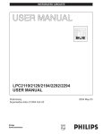
1
Serial/CAN-Gateway
SerCAN-ARM7/RMD
User Manual
EMS
Thomas Wünsche
Serial/CAN Gateway
SerCAN-ARM7/RMD
User manual SerCAN-ARM7/RMD
Document version:
1.03
Documentation date: May 05th, 2011
This document describes the functionality of the SerCAN-ARM7/RMD
hardware with firmware version 2.00. Please contact EMS Dr. Thomas
Wünsche, if you have a module with different firmware.
No part of this document or the software described herein may be
reproduced in any form without prior written agreement from EMS Dr.
Thomas Wünsche.
For technical assistance please contact:
EMS Dr. Thomas Wünsche
Sonnenhang 3
D-85304 Ilmmünster
Tel. +49-8441-490260
Fax +49-8441-81860
Our products are continously improved. Due to this fact specifications may
be changed at any time and without announcement.
WARNING:
2
EMS hardware and software may not be used in
applications where damage to life, health or private
property may result from failures in or caused by
these components.
EMS Dr. Thomas Wünsche
SerCAN-ARM7/RMD
Serial/CAN Gateway
Content
1
2
3
4
Overview
5
1.1 Features
1.2 General Description
1.3 Ordering Information
5
5
5
Handling
7
2.1 Connection
2.2 Operation
2.3 Configuration
2.3.1 Configuration File
2.3.2 Programming the Device
2.4 LED
7
7
7
7
10
12
Technical Data
13
3.1 Pin Assignment
3.2 Limiting Values
3.3 Nominal Values
13
14
14
Appendix
15
4.1 Configuration File Example
4.2 Standard CAN Baud Rates
15
15
EMS Dr. Thomas Wünsche
3
Serial/CAN Gateway
SerCAN-ARM7/RMD
THIS PAGE INTENTIONALLY LEFT BLANK
4
EMS Dr. Thomas Wünsche
SerCAN-ARM7/RMD
1
Serial/CAN Gateway
Overview
1.1 Features
• Connection of a CAN network to a RS232 interface
• Filtering of CAN messages
• CAN bus activity displayed by LED
• Configuration via RS232 connection
• Wiring using a multiway connector
• Available also with low speed CAN transceiver NXP TJA1054
1.2 General description
The Serial/CAN gateway SerCAN-ARM7 connects a CAN network to
a RS232 interface. The capability of having different baud rates on
the CAN side as well as on the RS232 side marks the devices a
versatile tool for a lot of applications. Bandwith differences between
CAN and RS232 may be overcome by CAN message filtering.
The device is also available with a low speed physical CAN interface
using NXP CAN transceiver TJA1054 (SerCAN-ARM7/RMD/LS).
The device is configured via the RS232 interface. Due to the intuitive
structure of the configuration file in ASCII format, programming and
administration is easy.
1.3 Ordering information
12-20-202-20
SerCAN-ARM7/RMD
12-20-203-20
SerCAN-ARM7/RMD/LS
EMS Dr. Thomas Wünsche
5
Serial/CAN Gateway
SerCAN-ARM7/RMD
THIS PAGE INTENTIONALLY LEFT BLANK
6
EMS Dr. Thomas Wünsche
SerCAN-ARM7/RMD
2
Serial/CAN Gateway
Handling
2.1 Connection
SerCAN-ARM7 has a multiway connector for flexible wiring of the
CAN interface and the power supply. The RS232 interface has a
standard SUB-D-9 male connector and is used for normal operation
as well as for the configuration purpose.
The connector assignment of the multiway connector and the RS232
interface is described in chapter "3.1 Pin assignment".
2.2 Operation
To start up the gateway just connect the power supply, the device
starts up automatically. As soon as the automatic diagnostic process
is successfully completed the green power LED lites up permanently.
Important note: Ex factory the device offers no configuration and
must be configured before its first run. Configuration instructions for
the gateway are located in chapter "2.3 Configuration".
2.3 Configuration
The gateway configuration process consists of two steps:
• Creating a configuration file
• Loading the configuration into the device
2.3.1 Configuration File
The configuration file is a text file with the extension *.gcf. This file
holds all data needed by the gateway for operation. A complete
sample configuration is located in chapter "4.1 Configuration File
Example".
The values can either be entered in decimal or hexadecimal
notation. Using the hexadecimal notation, the character 'x' has to be
entered directly before the particular value.
EMS Dr. Thomas Wünsche
7
Serial/CAN Gateway
SerCAN-ARM7/RMD
Some parameters are optional. If they are not defined, the gateway
uses default settings.
In the following all parameters are listed and described.
comment
#
The configuration file can be provided with comments. Comments
are prefaced with the character '#' and they end with the particular
line.
Example:
# 1st comment
key = value
version
# 2nd comment
version
The version number indicates the file format of the configuration file.
It must be 1 for the actual version.
Example:
version=1
configname
name assigned to the configuration
For easier identification of the programmed settings, the configration
can be labeled. The configuration name must not have more than 32
characters and must not contain space characters or tabs. If this key
is missing, no name will be assigned.
Example:
configname=MyOwnConfig
8
EMS Dr. Thomas Wünsche
SerCAN-ARM7/RMD
Serial/CAN Gateway
canbaudrate
CAN bit timing
The CAN bit timing key indicates the speed of the CAN interface.
This key is mandatory and is related directly to the CANBTR0
register of the used controller LPC2119. This allows most flexible
customization of the baudrate settings. The basic CAN clock is
48MHz.
Example:
# 500 kBaud
canbaudrate = x001c0005
serialbaudrate
serial baud rate
The serial baudrate key is optional. If it is not set, the default
baudrate of 57600 baud will be used. A particular value is calculated
with the following equation:
serialbaudrate = 48000000/(16*BAUDRATE)
The results for some standard values are given below:
9600 Baud
19200 Baud
38400 Baud
57600 Baud
115200 Baud
:
:
:
:
:
312
156
78
52
26
The line settings for the RS232 interface is always 8 data bits, no
parity, 1 stop bit (8N1).
The maximum usable baud rate is limited by the serial transceiver
chip to 115200 baud.
Please note, that if a serial baud rate is programmed, which is not
supported by the PC used for the configuration process, a
reconfiguration may become hard to accomplish.
Example:
# serial baud rate set to 57600
serialbaudrate=52
EMS Dr. Thomas Wünsche
9
Serial/CAN Gateway
bus off
SerCAN-ARM7/RMD
bus off behavior
This key specifies the period of time in milliseconds, which will pass
by until the gateway gets bus on again after a bus off condition has
occured. If this value is not defined, the device remains in bus off
state. If a bus off time of 0 milliseconds is set, the gateway tries
immediately to get bus on again.
Example:
busoff=100
sfilter, xfilter
filter key
This key defines which received CAN messages will be filtered out
or not. Either a particular identifier or a range of identifiers can be
specified. A message which should pass to the RS232 interface
must have a filter rule set. The "sfilter" key relates to 11bit identifier
messages, whereas "xfilter" relates to 29bit identifier.
Example:
# A range of 11bit messages starting with id 0 and
# ending with id 100h will pass the filter.
sfilter=x0-x100
# A range of 29bit messages starting with id 100h and
# ending with id 1000h will pass the filter.
xfilter=x0-x10
2.3.2 Programming the Device
SerCAN-ARM7 is programmed by means of the configuration
software. It offers the possibility to configure the gateway via the
RS232 interface. A "nullmodem" cable has to be used to connect to
the host PC.
The "Program Settings" have to be set to:
• SerCAN-ARM7/RMD
• Program configuration
• a configuration file
10
EMS Dr. Thomas Wünsche
SerCAN-ARM7/RMD
Serial/CAN Gateway
The "Interface Settings" have to be set to:
• Use RS232 interface
• the used PC serial interface port
• the serial baudrate used by the SerCAN-ARM7 device
Within the "Device Settings" the serial number of the SerCAN-ARM7
has to be set. The serial number can be found on a label on the rear
side of the device.
After all settings are made a click on the "Process" button starts the
download. Do not remove power from the device until the process
has finished.
Screenshot of the download tool:
EMS Dr. Thomas Wünsche
11
Serial/CAN Gateway
SerCAN-ARM7/RMD
2.4 LED
The device status is displayed by three LEDs.
Power
On
The device is CAN bus on and in normal operation mode
Off
The device is CAN bus off
Blinking
The device is in programming mode
CAN Active
12
On
There is CAN bus activity
Off
There is no CAN bus activity
EMS Dr. Thomas Wünsche
SerCAN-ARM7/RMD
3
Serial/CAN Gateway
Technical Data
3.1 Pin Assignment
Pin Assignment multiway connector SerCAN-ARM7/RMD
Pin
Signal
Description
1
+24V
+24 Volt power supply
2
GND
Ground*
3
GND
Ground*
4
CAN_H
CAN high bus line
5
CAN_L
CAN low bus line
6
GND
Ground*
7
GND
Bootloader (connect to Vcc to enter bootloader mode)
8
GND
Bootloader (connect to GND to enter bootloader mode)
Pin Assignment multiway connector SerCAN-ARM7/RMD/LS
Pin
Signal
Description
1
+24V
+24 Volt power supply
2
GND
Ground*
3
GND
Ground*
4
CAN_H
CAN high bus line
5
CAN_L
CAN low bus line
6
GND
Ground*
7
RTH
Connected with Pin 4 by a 5k6 resistor and
RTH pin of TJA1054 CAN transceiver
8
RTL
Connected with Pin 5 by a 5k6 resistor and
RTL pin of TJA1054 CAN transceiver
*internal connected
EMS Dr. Thomas Wünsche
13
Serial/CAN Gateway
SerCAN-ARM7/RMD
Pin assignment RS232
Pin
Signal
1
Description
not connected
2
RxD
Receive signal
3
TxD
Transmit signal
4
5
not connected
GND
6
Ground
not connected
7
RTS
not used
8
CTS
not used
9
not connected
3.2 Limiting Values
Parameter
Min.
Max.
Unit
Storage temperature
-20
80
°C
Operating temperature
0
60
°C
Supply voltage
-100
30
V
Parameter
Min.
Max.
Unit
Supply voltage
10
30
V
CAN Baudrates
10
1000
kBit/s
3.3 Nominal Values
14
EMS Dr. Thomas Wünsche
SerCAN-ARM7/RMD
4
Serial/CAN Gateway
Appendix
4.1 Configuration File Example
# Serial/CAN Gateway SerCAN-ARM7 configuration file
# Version number of configuration file
version=1
# CAN baud rate set to 500kBaud
canbaudrate=x001C0005
# RS232 baud rate set to 57.6 kBaud
serialbaudrate=52
# set CAN bus off recovery time to 500ms
busoff=500
# filter settings
# all 11bit CAN identifier are routed
sfilter=x0-x7FF
# all 29bit CAN identifiers are routed
xfilter=x0-x1FFFFFFF
4.2 Standard CAN Baud Rates
baud rate
canbaudrate value
1000 kBaud
0x00140005
800 kBaud
0x00160005
500 kBaud
0x001C0005
250 kBaud
0x001C000B
125 kBaud
0x001C0017
100 kBaud
0x001C001D
50 kBaud
0x001C003B
20kBaud
0x001C0095
10 kBaud
0x001C012B
EMS Dr. Thomas Wünsche
15
Serial/CAN Gateway
SerCAN-ARM7/RMD
4.3 Serial Protocol Specification
A block oriented protocol is used for message exchange between
RS232 and CAN.
Format of a data block:
Start
Type
Length Data
1 byte
1 byte
1 byte
Checksum End
'length' - 4 bytes 2 bytes
1 byte
The 'length' byte counts the number of bytes in the fields 'type',
'length', 'data' and 'checksum'. The two checksum bytes contain the
byte by byte summarization of the fields 'type', 'length' and 'data'.
A number of special characters are used. Reserved characters have
values less or equal 7.
The following three special characters are used:
Special character Value Description
BEGINOFDATA
0x00
Marks the start of a block
ENDOFDATA
0x01
Marks the end of a block
ESCAPE
0x02
The following character is no special
character. This allows the transmission
of special characters in the fields 'type',
'length', 'data' and 'checksum'.
In case that a special character has to be transmitted within the data
field, it must be preceeded by an ESCAPE character and the most
significant bit of the character has to be set.
Example: Transmission of 0x01
Transmitted is 0x02 (ESCAPE) followed by 0x81 (0x01|0x80).
16
EMS Dr. Thomas Wünsche
SerCAN-ARM7/RMD
Serial/CAN Gateway
The meaning of the bytes in the 'data' field is indicated by the 'type'
field.
Type
Value
Description
CAN
0x08
Denotes a CAN message with 11bit identifier
XCAN
0x09
Denotes a CAN message with 29bit identifier
A message block of type 'CAN' has the following structure:
ID
RTR
2 bytes
1 byte
low byte first 0xFF: RTR frame
0x7F: data frame
Length Data
1 byte
data frame: Number of
data bytes corresponding
to 'Length'
RTR frame: 0 bytes
A message block of type 'XCAN' has the following structure:
ID
RTR
4 bytes
1 byte
low byte first 0xFF: RTR frame
0x7F: data frame
EMS Dr. Thomas Wünsche
Length Data
1 byte
data frame: Number of
data bytes corresponding
to 'Length'
RTR frame: 0 bytes
17
Serial/CAN Gateway
SerCAN-ARM7/RMD
THIS PAGE INTENTIONALLY LEFT BLANK
18
EMS Dr. Thomas Wünsche
SerCAN-ARM7/RMD
Serial/CAN Gateway
THIS PAGE INTENTIONALLY LEFT BLANK
EMS Dr. Thomas Wünsche
19