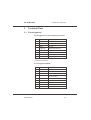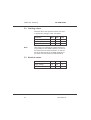
1
CAN/CAN-Gateway
CG-ARM7/RMD
User Manual
EMS
THOMAS WÜNSCHE
Sonnenhang 3
D-85304 Ilmmünster
Tel. +49-8441-490260
Fax +49-8441-81860
CAN/CAN - Gateway
CG-ARM7/RMD
User manual CG-ARM7/ RMD
Document version: 2.00
Documentation date: June 22nd, 2005
No part of this document or the software described herein may
be reproduced in any form without prior written agreement
from EMS Dr. Thomas Wünsche.
For technical assistance please contact:
EMS Dr. Thomas Wünsche
Sonnenhang 3
D-85304 Ilmmünster
Tel. +49-8441-490260
Fax +49-8441-81860
Our products are continuously improved. Due to this fact
specifications may be changed at any time and without
announcement.
WARNING:
ii
EMS hardware and software may not be
used in applications where damage to life,
health or private property may result from
failures in or caused by these components.
User Manual
CG-ARM7/RMD
CAN/CAN - Gateway
Table of contents
1
Overview . . . . . . . . . . . . . . . . . . . . . 1
1.1
Features . . . . . . . . . . . . . . . . . . . . . 1
1.2
General description . . . . . . . . . . . . . . . . 1
1.3
Ordering information . . . . . . . . . . . . . . . 1
2
Handling . . . . . . . . . . . . . . . . . . . . . 2
2.1
Connection . . . . . . . . . . . . . . . . . . . . 2
2.2
Operation . . . . . . . . . . . . . . . . . . . . . 2
2.3
Configuration . . . . . . . . . . . . . . . . . . . 2
2.3.1 Configuration file . . . . . . . . . . . . . . . . . 3
2.3.2 Programming the device . . . . . . . . . . . . . 9
2.4
Display . . . . . . . . . . . . . . . . . . . . . 12
3
Technical specifications. . . . . . . . . . . . 14
3.1
Pin assignment . . . . . . . . . . . . . . . . . 14
3.2
Limiting values . . . . . . . . . . . . . . . . . 15
3.3
Nominal values . . . . . . . . . . . . . . . . . 15
4
Appendix . . . . . . . . . . . . . . . . . . . . 16
4.1
Configuration file sample . . . . . . . . . . . . 16
4.2
Standard baudrates . . . . . . . . . . . . . . . 17
User Manual
iii
CG-ARM7/RMD
1
CAN/CAN - Gateway
Overview
1.1 Features
• Connection of two physically separated
•
•
•
•
CAN networks
Filtering and mapping of identifiers
Bus activity displayed by LED
Gateway configuration via RS232 or CAN
Wiring using a multiway connector
1.2 General description
The CAN/CAN gateway CG-ARM7 connects
two physically divided CAN networks. The capability of having individual baudrates on both
segments, enables routing between them.
The filtering of single identifiers or ranges of
identifiers lessens the busload. The mapping
of single or ranges of identifiers qualifies
CG-ARM7 to be used under difficult higher
level protocol conditions.
The device is configured via serial interface or
via CAN network. Due to the intuitive structure
of the configuration file in ASCII format,
programming and administration is very easy.
1.3 Ordering information
12-20-401-10
User Manual
CG-ARM7/RMD
1
CAN/CAN - Gateway
2
CG-ARM7/RMD
Handling
2.1 Connection
The CG-ARM7 possesses a multiway connector for flexible wiring of the CAN interfaces and
the power supply. The RS232 interface on the
device is used for programming and for the
output of diagnostic information. For normal
operation it is not required.
The connector assignment of the multiway
connector and the RS232 interface is located
in chapter “3.1 Pin assignment” in this manual
or on your devices front panel.
2.2 Operation
To start up the gateway just connect the power
supply, the device starts automatically. As
soon as the automatic diagnostics is completed successfully, the green power LED lites up
permantly.
Important note: Ex factory the device offers
no configuration and must be configured before it is first run. Configuration instructions for
the gateway are located in chapter “2.3 Configuration”.
2.3 Configuration
The gateway configuration process consists of
two steps:
• Creating a configuration file
2
User Manual
CG-ARM7/RMD
CAN/CAN - Gateway
• Storing the configuration file into the
gateway
2.3.1 Configuration file
The configuration file is a text file with the extension *.gcf. This file holds all data needed by
the gateway for operation. A complete sample
configuration is located in chapter “4.1 Configuration file”.
The values can either be entered in decimal or
hexadecimal notation. Using the hexadecimal
notation, put the character “x” directly before
the particular value.
There are two types of parameters, general
parameters and routing settings. General
parameters include operating information for
the gateway. Routing settings are used for
mapping and filtering of identifiers.
Some parameters are optional. If they are not
defined, the gateway uses default settings.
Simultaneous programming of several devices
is not possible. It must be guaranteed, that
each device can be clearly identified.
In the following all parameters are listed and
described.
#
comment
The configuration file can be provided with
comments. Comments are prefaced with the
character “#” and they end with the particular
line.
User Manual
3
CAN/CAN - Gateway
CG-ARM7/RMD
Example:
# 1st comment
key = value # 2nd comment
version
version
The gateway requires a version number to
identify the programmed configuration. The
version number for the CG-ARM7 standard
version is 1. This key must exist in each configuration file.
Important: The version is not the version of
the configuration! The version display what
kind of configuration is be loaded!
Example:
version = 1
btr
bit timing
The bit timing key indicates the speed of the
particular CAN channel. BTR1 indicates the
baud rate for CAN channel 1, BTR2 the baudrate for CAN channel 2. Both keys must exist
in each configuration file.
This keys are directly related to the CANBTR
registers of the used controller LPC2119. This
allows most flexible customization of the baudrate settings. The basic can clock is 48 MHz.
Example:
# CAN channel 1: 1Mbit/s
btr1 = x00140005
# CAN channel 2: 500KBit/s
btr2 = x001C0005
4
User Manual
CG-ARM7/RMD
CAN/CAN - Gateway
Standard speeds recommend by CiA are located in chapter “4.2 Standard baudrates”.
pidin,
pidout
program identifier
The program identifiers (PIDs) are required for
the gateway configuration via CAN. If you do
not want to program the gateway via CAN, you
can remove this keys from your configuration
file.
The PIDs determine which identifiers will be
used for programming the gateway. “pidin” defines the identifier the configuration software
uses to send requests to the gateway. The key
“pidout” defines the identifier which the gateway uses to reply to the configuration software.
For CAN channel 1 and CAN channel 2 different PIDs can be set. But it is also possible to
program the gateway just via one CAN channel. To set the wanted identifiers for CAN
channel 1 use the keys “pidin1” and “pidout1”.
For CAN channel 2 use the keys “pidin2” and
“pidout2”.
To use a 29-bit identifier prepend the character
“x” before the particular key. Without prefix before the key 11-bit identifiers will be sent.
Example:
# PIDs for CAN channel 1
# CAN 1: 11-bit IN-Id: 0x5
pidin1 = x5
# CAN 1: 29-bit OUT-Id: 0xA00
xpidout1 = xA00
User Manual
5
CAN/CAN - Gateway
CG-ARM7/RMD
# PIDs for CAN channel 2
# CAN 2: 29-bit IN-Id: 0x6E
xpidin2 = x6E
# CAN 2: 29-bit OUT-Id: 0x1FFE
xpidout2 = x1FFE
name
configuration label
For easier identification of the programmed
settings, the configuration can be labeled. The
configuration name must not have more than
32 characters and must not contain space characters or tabs. If this key is missing, no name
will be assigned to the configuration.
Example:
name = standard_configuration
deviceid
device id
During the configuration process via CAN the
device has to be uniquely selected in the network. This process is based on the serial number of the device.
If there is the need to have the configuration
process independent of the serial number, a
device id can be assigned. Then the identification of the device depends on the device id
and not on the serial number.
Care must be taken to use a particular device
id just once in a network, if more than one gateways is used.
The device id can have values between 1 and
99999999.
Example:
deviceid = 50
6
User Manual
CG-ARM7/RMD
CAN/CAN - Gateway
busoff
bus off behavior
This key defines the period in milliseconds,
which shall be waited until the gateway gets
bus on again after a bus off condition has occured. If this value is not defined, the device
remains in bus off state. If a bus off time of 0
milliseconds is set, the gateway tries immediately to get bus on again.
Example :
busoff = 100
password password
Using a password, the gateway can be protected against unauthorized access. If the key is
not defined or the value is set to 0, password
protection is disabled. The password is an up
to 14-digit hexadecimal value.
The password protection supports two security
levels.
For the highest security level the highest bit
(56th bit) of the password must be set to 1.
This security level prevents any communication with the gateway, if the device has not been
unlocked with the correct password before.
At the normal security level, the highest bit
(56th bit) is 0. Read out of information about
the gateway and the configuration is enabled.
Changing the configuration however is not
possible!
Example:
# Security: high
User Manual
7
CAN/CAN - Gateway
CG-ARM7/RMD
password = 80 07 05 AF D6 B0 D1
# Security: normal
password = 00 07 05 AF D6 B0 D1
fil
routing
The routing settings contain the filtering and
mapping rules for a single identifier or ranges
of identifiers. Only stated identifier or ranges of
identifiers are transmitted and, if existent, the
adequate mapping rule is applied. All incoming
messages with identifiers to which no rule applies are ignored (defined program identifiers
excepted). Additionally the frame format must
be set within the filtering rules.
Key structure:
Different from the basic keys, the routing key is
constructed in a more complex way. The key
specifies 3 criteria:
[inff] fil channel [outff] =
...
1. inff: Defines the frame format for incoming
messages.
The frame format for incoming messages specifies whether the filtering rule is applied to
standard or extended messages. If inff is set to
‘s’ standard frame format is specified. When
set to ‘x’ the extended frame format is defined.
2. channel: Defines the channel number.
The channel number specifies whether the filtering rule is applied to incoming messages on
CAN channel 1 or on CAN channel 2.
8
User Manual
CG-ARM7/RMD
CAN/CAN - Gateway
3. outff: Defines the frame format for outgoing
messages.
The frame format for outgoing messages specifies whether the result of the filtering rule is
sent via standard or extended identifier. If outff
is set to ‘s’ standard frame format is specified.
When set to ‘x’ extended frame format is defined.
Structure of the filtering rule:
Now that the key defines to which message
the rule applies, further selections have to be
made. The filtering rule in turn specifies 3 criteria:
… = sid [- eid] [: mid]
1. sid: Defines the identifier the filtering rule is
applied to.
If a range of identifiers is defined, sid is the
start identifier. If the prefix ‘x’ is before the value the identifier is interpreted as a hexadecimal number.
2. eid: Defines the end identifier for ranges of
identifiers.
If no range of identifiers is used, the value is
not needed. If the prefix ‘x’ is before the value
the identifier is interpreted as a hexadecimal
number.
3. mid: Defines the mapping identifier.
The mapping identifier states the start identifer,
to which the single identifier or the range of
identifiers is mapped. Should the identifiers not
be mapped it is not needed to set this value. If
the prefix ‘x’ is before the value the identifier is
interpreted as a hexadecimal number.
User Manual
9
CAN/CAN - Gateway
CG-ARM7/RMD
Example:
# The via CAN channel 1
# received extended
# identifiers in the range
# of 0x30 to 0x40 are
# sent via CAN channel 2
# as standard identifiers in
# the range of 0x400 to
# 0x410.
xfil1s = x30 - x40 : x400
# The via CAN channel 2
# received extended
# identifier 0x1FFFFFFF
# is sent via CAN channel 1
# as extended identifier
# with the value 0x01.
xfil2x = x1FFFFFFF : x1
# The via CAN channel 1
# received standard
# identifiers in the range
# of 0x100 to 0x200 are
# sent via CAN channel 2
# as standard identifiers
# in the range of 0x100
# to 0x200.
sfil1s = x100 - x200
2.3.2 Programming the device
CG-ARM7 is programmed by means of the
configuration software. It offers the possibility
to configure the gateway via serial connection
or via CAN. For the configuration a serial cable
or a PC-CAN interface of EMS Dr. Thomas
Wuensche is needed.
10
User Manual
CG-ARM7/RMD
CAN/CAN - Gateway
Setting up the PC interface:
The PC interface is set in the upper left field.
First you choose, if the gateway shall be accessed via RS232 or via CAN interface. If the
configuration software recognizes, that you do
not use an interface of EMS Dr. Thomas Wuensche you can not select CAN as your interface.
Next the PC interface with which you want to
connect to the CG-ARM7 has to be chosen. If
you have selected RS232 as interface before,
you set up the COM interface here. If you have
chosen CAN, you select your CAN interface
here.
Speed can only be selected, when a connection via CAN has been made. Choose a standard baudrate compliant to the CiA or choose
“Custom” to insert a user defined setting. Your
selected baudrate must be the same as the
baudrate of the gateway.
If no configuration is in the gateway it is not
possible to communicate with the gateway via
CAN.
User Manual
11
CAN/CAN - Gateway
CG-ARM7/RMD
Process selection:
In the right upper field of the configuration software you choose the process, you want to
perform.
• Program new configuration
•
•
With this process you can program a
new configuration to the device. Before
starting you have to select the configuration you want to write to the gateway.
Remove configuration from device
This process deletes the current configuration on the CG-ARM7. Afterwards
the gateway is in delivery state again. It
is not needed to delete the configuration
before a new one is programed, as this
is done automatically.
Read device information
Here information about the gateway and
the configuration within can be read out.
12
User Manual
CG-ARM7/RMD
CAN/CAN - Gateway
Optional device settings
If the CG-ARM7 is password protected, you
must activate the field “password” and fill in the
correct password. Depending on the security
level, it is possible to request information about
the device even without password.
If CAN has been chosen as the PC interface
the “Inbound Program Identifier” (pidin), the
“Outbound Program Identifier” (pidout) and the
frame format for the program identifiers have
to be set. At last the serial number or the configured device id of the device has to be inscribed for explicit identification. If you use only
one gateway in the network, you can also inscribe the value ‘0’ here. Never use the value
‘0’, if there are more than one CG-ARM7 gateways in the network.
Starting the download:
To start the download process press start. The
operation may take a while, do not disconnect
the power supply to the device during the configuration process. At that time the routing
functionality of the gateway is deactivated. After successful completion no status message
is displayed. If an error occures a status message is displayed.
2.4 Display
The device status is displayed by three LEDs.
Power
On
User Manual
The device is in normal operation
mode. Routing of CAN messages is
enabled.
13
CAN/CAN - Gateway
CG-ARM7/RMD
The device is in programming mode.
Blinking Routing of CAN messages is
disabled.
CAN 1 Active
On
There is bus activity on CAN 1.
CAN 2 Active
On
14
There is bus avtivity on CAN 2.
User Manual
CG-ARM7/RMD
3
CAN/CAN - Gateway
Technical Data
3.1 Pin assignment
Pin assignment of the multiway connector
Pin
Signal
Description
1
+24V
+24 Volt power supply
2
GND
Ground*
3
GND
Ground*
4
CAN1-H
CAN1-High Buswire
5
CAN1-L
CAN1-Low Buswire
6
GND
Ground*
7
CAN2-H
CAN2-High Buswire
8
CAN2-L
CAN2-Low Buswire
* Internal connected
Pin assignment RS232
Pin
Signal
2
RxD
Receive signal
3
TxD
Transmit signal
not connected
4
5
GND
6
Ground
not connected
7
RTS
not used
8
CTS
not used
9
User Manual
Description
not connected
1
not connected
15
CAN/CAN - Gateway
CG-ARM7/RMD
3.2 Limiting values
Stresses above the specified values can lead
to permanent damage of the CG-ARM7.
Parameter
Min.
Max.
Unit
Storage temperature
-20
80
C
0
60
C
-100
30
V
Operating temperature
Supply voltage
Note:
With respect to methods of measurement it is
not possible to have ESD protection circuits at
the CAN terminals. ESD protection on this terminals is determined by the ESD capability of
the used CAN transceiver (Philips 82C251).
3.3 Nominal values
Parameter
16
Min.
Max.
Unit
Supply voltage
10
30
V
Baudrates
10
1000
kBit/s
User Manual
CG-ARM7/RMD
4
CAN/CAN - Gateway
Appendix
4.1 Configuration file example
# Gateway CG-ARM7/RMD configuration file
# Baudrate CAN interface 1 - 1000 kbps
btr1=x00140005
# Baudrate CAN interface 2 - 500 kbps
btr2=x001C0005
# Version number of configuration file
version=1
# Device ID
deviceid=120000
# Set bus off recovery time to 1000 ms
busoff=1000
# Password protection: security level
# normal
password=11 AA 33 BC
# Configuration name
name=router
# Program identifier CAN channel 1
pidin1=x1
# Standard identifier 0x01
xpidout1=x2
# Extended identifier 0x02
# Program identifier CAN channel 2
xpidin2=x10
# Extended identifier 0x10
xpidout2=x20 # Extended identifier 0x20
# Filter settings
User Manual
17
CAN/CAN - Gateway
CG-ARM7/RMD
# All standard identifiers from CAN channel
# 1 are sent as standard identfiers to CAN
# channel 2
sfil1s=x0-x7FF
# All standard identifiers form CAN channel
# 2 are sent as standard identifiers to CAN
# channel 1
sfil2s=x0-x7FF
# All extended identifiers form CAN channel
# 1 are sent as extended identifiers to CAN
# channel 2
xfil1x=x0-x1FFFFFFF
# All extended identifiers form CAN channel
# 2 are sent as extended identifiers to CAN
# channel 1
xfil2x=x0-x1FFFFFFF
4.2 Standard baudrates
Speeds recommended by CIA:
Baudrate
1000 kbps
800 kbps
500 kbps
250 kbps
125 kbps
100 kbps
50 kbps
20 kbps
10 kbps
18
Bit Timing Register
0x00140005
0x00160005
0x001C0005
0x001C000B
0x001C0017
0x001C001D
0x001C003B
0x001C0095
0x001C012B
User Manual
CG-ARM7/RMD
CAN/CAN - Gateway
THIS PAGE INTENTIONALLY LEFT BLANK
User Manual
19