Download Manual: Ethernet CAN Interface
Transcript
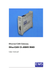
EtherCAN CI
User Manual
Documentation for Ethernet/CAN interface EtherCAN CI
version 2.1.
Document version: V3.0
Documentation date: June 16th, 2007
This documentation is not valid for EtherCAN CI version 2.0
and earlier versions.
No part of this document or the software described herein
may be reproduced in any form without prior written
agreement from EMS Dr. Thomas Wünsche.
For technical assistance please contact:
EMS Dr. Thomas Wünsche
Sonnenhang 3
Ethernet/CAN Interface
D-85304 Ilmmünster
EtherCAN CI
Tel.
+49-8441- 490260
Fax
+49-8441- 81860
Email: [email protected]
User Manual
Our products are continuously improved. Due to this fact
specifications may be changed at any time and without
announcement.
EMS
THOMAS WÜNSCHE
Sonnenhang 3
D-85304 Ilmmünster
Tel +49-8441-490260
Fax +49-8441-81860
WARNING:
ii
EtherCAN CI hardware and software may
not be used in applications where damage
to life, health or private property may result
from failures in or caused by these components.
EMS Dr. Thomas Wünsche
User Manual
EtherCAN CI
EtherCAN CI
Content
5.3.2
5.3.3
5.3.4
5.3.5
1 Overview . . . . . . . . . . . . . . . . . . . . . . . . 1
1.1
1.2
1.3
1.4
Attributes . . . . . .
General Description
Sample Applications
Ordering Information
.
.
.
.
.
.
.
.
.
.
.
.
.
.
.
.
.
.
.
.
.
.
.
.
.
.
.
.
.
.
.
.
.
.
.
.
.
.
.
.
.
.
.
.
.
.
.
.
.
.
.
.
.
.
.
.
.
.
.
.
.
.
.
.
1
1
2
2
User Manual
Device Configuration . . . . . . . . . . . . 23
CAN Server Startup Configuration . . . . . 24
Default Configuration upon Delivery . . . . 24
Sample cansrv/cansrv_udp Configuration File
. . . . . . . . . . . . . . . . . . . . . . . 25
2 Hardware . . . . . . . . . . . . . . . . . . . . . . . . 3
3 Software . . . . . . . . . . . . . . . . . . . . . . . . 4
3.1 Built-in Capabilities . . . . . . . . . . . . . . . . . 4
3.2 Communication and General Software . . . . . . . 4
3.2.1 cansrv . . . . . . . . . . . . . . . . . . . . 4
3.2.2 cansrv_udp . . . . . . . . . . . . . . . . . 8
3.2.3 Client Application . . . . . . . . . . . . . . 12
3.2.4 m4d . . . . . . . . . . . . . . . . . . . . . 12
3.2.5 User Accessible Flash . . . . . . . . . . . 12
3.2.6 wdog . . . . . . . . . . . . . . . . . . . . 14
3.2.7 fltool . . . . . . . . . . . . . . . . . . . . 14
3.2.8 route . . . . . . . . . . . . . . . . . . . . 16
3.2.9 led . . . . . . . . . . . . . . . . . . . . . 16
4 Electrical Characteristics . . . . . . . . . . . . . . 19
4.1 Absolute Limiting Values . . . . . . . . . . . . . 19
4.2 Nominal Values . . . . . . . . . . . . . . . . . . 19
5 Operating Instructions . . . . . . . . . . . . . . . . 20
5.1 Connection Scheme. . . . .
5.2 Installation . . . . . . . . . .
5.3 Configuration . . . . . . . .
5.3.1 General Configuration
EMS Dr. Thomas Wünsche
.
.
.
.
.
.
.
.
.
.
.
.
.
.
.
.
.
.
.
.
.
.
.
.
.
.
.
.
.
.
.
.
.
.
.
.
.
.
.
.
.
.
.
.
20
21
22
22
iii
iv
EMS Dr. Thomas Wünsche
User Manual
1
EtherCAN CI
EtherCAN CI
User Manual
king back to back, can bridge two CAN networks over an Ethernet connection.
Overview
1.1 Attributes
1.3 Sample Applications
EtherCAN CI offers a range of features which
make it valuable for many CAN based applications:
The field of application for EtherCAN CI is
wide. Some sample applications are detailed
in the following and supported by corresponding software:
• Connection of CAN systems to Ethernet
networks
• Online configuration of CAN networks
• Network setup and analysis
• Visualisation of process parameters in
• Coupling of CAN networks over
•
•
•
•
•
•
•
•
•
Ethernet
CAN interface for industrial applications
CiA DS-102 and IS0 11898 compatible
physical layer
Microcontroller Winbond W90N740 (32
Bit ARM7/80MHz) with additional CAN
controller NXP SJA1000
NXP PCA82C251 CAN transceiver
Galvanic decoupling between Ethernet
and CAN bus
Filtering and buffering of CAN traffic
Supports CAN protocols 2.0A and 2.0B
Serial interface for configuration
Embedded Linux operating system
CAN based systems.
1.4 Ordering Information
1.2 General Description
12-20-302-20
EtherCAN CI-ARM7/RMD
Ethernet/CAN interface with
32 bit microcontroller (ARM7
core) and CAN controller NXP
SJA1000
12-20-305-20
EtherCAN CI-ARM7/RMD M4D
Ethernet/CAN interface with
32 bit microcontroller (ARM7
core), CAN controller NXP
SJA1000 and CANopen
software M4D
The rail mountable Ethernet/CAN interface
EtherCAN CI transmits signals between a
CAN system and an Ethernet network.
Utilizing the Ethernet standard, EtherCAN is
usable in a wide range of applications. It can
be used as a standard CAN interface in a LAN
environment. Or two EtherCAN devices, wor-
EMS Dr. Thomas Wünsche
1
2
EMS Dr. Thomas Wünsche
User Manual
2
EtherCAN CI
Hardware
EtherCAN CI
3
User Manual
Software
EtherCAN CI includes a Winbond W90N740
(ARM7 core) with 80MHz clock. In addition,
the device has 16MB SDRAM and 2MB Flash.
The connection to the CAN bus is provided by
a CAN controller of type NXP SJA1000 and
supports the CAN protocols 2.0A and 2.0B.
3.1 Built-in Capabilities
• an Embedded Linux operating system
• a powerful TCP/IP stack
• a CAN server application
• Watchdog functionality
EtherCAN CI includes a CAN segment with
two connectors of type D-Sub 9, the pin assignment complies to CiA DS-102 standard.
Besides the CAN signals the connectors also
carry the power supply for EtherCAN CI.
EtherCAN CI includes an Ethernet connector
(Twisted Pair, 10/100MBit/s) and a serial connector (D-Sub).
3.2 Communication and General Software
The communication software normally consists
of two parts. One part is executed by the processor inside EtherCAN CI (server application). The other part (client application) runs on
a device connected to EtherCAN CI via the
Ethernet. This device can be a PC or any
other device supporting IP networking.
LED’s
Server and client use an ASCII protocol when
communicating via TCP or UDP. This protocol
is not included in this document, but can be
obtained on demand.
Explanation of the different LED’s on EtherCAN:
CAN Active: this LED flickers in case of traffic
on the CAN bus.
Eth. Active: this LED flickers in case of traffic
on the Ethernet network.
Eth. Link: this LED is lit if another device was
detected within the network.
EtherCAN CI is delivered with a monitor program running under Windows OS as client application.
3.2.1 cansrv
There are three status LEDs on EtherCAN CI
usable by application software. Currently
cansrv, cansrv_udp and led are using them.
Please refer to the related program documentation for details.
EMS Dr. Thomas Wünsche
3
The CAN server application cansrv is intended
to provide a point to point communication link
with a client over a TCP connection.
While the main purpose is the connection with
a PC based client application, cansrv can also
be used in a back to back configuration with
another EtherCAN CI device. In this configura-
4
EMS Dr. Thomas Wünsche
User Manual
EtherCAN CI
EtherCAN CI
tion one device acts as a server and the other
as a client, they form a transparent link for the
CAN networks connected.
User Manual
-f (--config-file) CONFIGFILE
Allows the use of a configuration file for
baudrate settings and identifier filtering.
A sample configuration file can be found in
5.3.5. A baudrate given within CONFIGFILE
cannot be changed dynamically by a connected client.
Once it is started as server it listens on a port
for incoming connections. After the connection
is established the client is able to send and receive CAN messages and to configure the
CAN parameters of the remote CAN controller.
-p (--port) PORT
The port to listen at for incoming connections
(default is 1500).
The use of a configuration file allows to specify
more detailed CAN controller register values
and to configure a software filter for standard
identifier CAN messages.
-w (--trigger-watchdog)
This option triggers the watchdog cyclicly.
If this option is not set, an other application
must trigger the watchdog.
The following command line options are available for the CAN server application (both
short and long options are supported):
-v (--version)
Show the version information.
-o (--busoff-recovery-time) TIMEOUT
This time specifies the period which is waited
after a bus off event before the CAN controller
is reinitialized. The time value is given in ms,
0 indicates to immediately go bus on again. As
default the option is not set and this means actually “do not go bus on again”.
-b (--baudrate) BAUDRATE
The CAN baudrate used.
1000|800|500|250|125|100|50|25|20|10 kBaud
can be set with this option. Please notice that
a baudrate specified with this option can not
be changed dynamically by a connected client.
To form a bridge for two independent CAN
networks two EtherCAN devices (connected
over their Ethernet interfaces) can be used,
one running as server, the other as client. In
this case, the following parameters can be
used:
-d (--device-file) DEVICE
The device, default is /dev/can0. This option is
documented for completeness only. It is used
on products where more than one CAN channel is available.
-i (--ip-address) IPADDRESS
IP address of the server the client wants to
connect to. The parameter ‘-p’ (see above)
should then also be used.
-h (--help)
Show the available options.
-k (--keep-alive)
The connection will be running using a keep
EMS Dr. Thomas Wünsche
5
6
EMS Dr. Thomas Wünsche
User Manual
EtherCAN CI
EtherCAN CI
alive mechanism that reestablishes broken
connections.
Please notice: In order for the keep alive mechanism to run properly, both applications
(server and client) have to be started with the
‘-k’ option.
For debugging purposes the following options
can be used. For performance reasons it is not
recommended to use them in production systems:
Status 1:
“On” means cansrv program is started.
“Off” means cansrv is not started or has correctly terminated.
Status 2:
“Blinking” means cansrv ethernet communication is in state of connecting or listening.
“On” means ethernet communication link is
established.
Status 3:
“On” means CAN controller state is bus on.
“Off” means CAN controller state is bus off.
Examples:
-t (--show-tcp-frames)
Show TCP frames on the serial terminal
cansrv -p 1500
This will start cansrv as a server listening on
port 1500. This is the default setting.
As no baudrate is specified at the command
line, the server will initialize its CAN controller
with the parameters sent by the client.
-c (--show-cpc-frames)
Show CPC messages on the serial terminal
Server mode:
If option ‘-i’ is not given, EtherCAN will start in
servermode and listen on <PORT> for incoming connections.
If options ‘-b’ or ‘-f’ are given a baudrate setting via TCP/IP will be ignored.
Client mode (back-to-back operation only):
If option ‘-i’ is given, the CAN server will start
in client mode. It will try to open a connection
to <IPADDRESS> and <PORT> of the server.
A baudrate option with ‘-b’ or ‘-f’ is mandatory.
If option ‘-f’ is given and there is a baudrate
configured within this file, it will not override
<BAUDRATE> given by the -b option.
If option ‘-k’ is set a keep alive mechanism will
reestablish a broken connection.
cansrv -p 1500 -i 192.168.0.176 -k -b 500
This will start cansrv as a client which will try
to connect to the host with IP address
192.168.0.176 on port 1500. The client will use
a baudrate of 500 kBaud and will use the keep
alive mechanism. It will also advertise this
baudrate to the client. The client takes it, if no
-b or -f option is set.
3.2.2 cansrv_udp
The application cansrv_udp is intended to provide a point to point communication link with
another EtherCAN CI device. It uses a UDP
based protocol, which offers better latency
timing than TCP does. The reliability of the
messages is handled completely by the application.
The cansrv program uses the status LEDs as
described here:
EMS Dr. Thomas Wünsche
User Manual
7
8
EMS Dr. Thomas Wünsche
User Manual
EtherCAN CI
EtherCAN CI
Once it is started it listens on a port for incoming connections. After the connection is
established the client is able to send and receive CAN messages and to configure the
CAN parameters of the CAN controller.
-a (--ack-timeout) TIMEOUT
This option changes the acknowledge timeout
given in µs.
The acknowledge timeout is the time within
which a transmitted UDP datagram packet has
to be acknowledged by the receiver.
If this option is not given the default value
10000 is applied.
The use of a configuration file allows to specify
detailed CAN controller register values and to
configure a filter for standard identifier CAN
messages.
-d (--device) DEVICE
The device, default is /dev/can0. This option is
documented for completeness only. It is used
on products where more than one CAN channel is available.
The command line parameters are described
in the following:
-h (--help)
Show the available options.
-b (--baudrate) BAUDRATE
The CAN baudrate used on this segment.
1000|800|500|250|125|100|50|25|20|10 kBaud
can be set with this option.
A baudrate given will be advertised to the opposite side, where it is used, if option -r is set
there.
-v (--version)
Show the version information.
-w (--trigger-watchdog)
This option triggers the watchdog cyclicly. If
this option is not set, an other application must
trigger the watchdog.
-f (--configfile) CONFIGFILE
Allows the use of a configuration file for
baudrate settings and identifier filtering. A
sample configuration file can be found in 5.3.5.
The baudrate parameters (btr0 and btr1) given
within this file are treated like it is described
with option -b.
-p (--listen-port) PORT
The port to listen for incoming datagrams.
If this option is not given the default value is
1500.
-e (--dest-port) PORT
The port where the destination udpsrv has to
be listening at.
If this option is not given the default value is
1500.
-x (--btr0) BTR0
Set BTR0 register explicitly.
-y (--btr1) BTR1
Set BTR1 register explicitly.
-i (--dest-ip)
The IP address for outgoing datagrams e.g.
172.0.1.2.
EMS Dr. Thomas Wünsche
User Manual
-r (--accept-remote-baudrate)
If this option is set a baudrate given from the
9
10
EMS Dr. Thomas Wünsche
User Manual
EtherCAN CI
EtherCAN CI
User Manual
remote side is always accepted.
As default this option is not set.
EtherCAN “B” with IP address 192.168.1.95:
cansrv_udp -i 192.168.1.94 -b 500
-o (--busoff-recovery-time) TIMEOUT
This time specifies the period which is waited
after a bus off event before the CAN controller
is reinitialized. The time value is given in ms,
0 indicates to immediately go bus on again. As
default the option is not set and this means actually “do not go bus on again”.
This will establish a connection between two
EtherCAN CI where unit “A” has the
IP address 192.168.1.94 and unit “B” has the
IP address 192.168.1.95. A baudrate of 500
kbaud is used on both sides.
3.2.3 Client Application
The client application (’monitor.exe’) currently
only runs on a PC with Windows OS. Please
refer to the manual for the monitor application
which is available separately. This client needs
the cansrv program to be run on EtherCAN CI.
The cansrv_udp program uses the status
LEDs as described here:
Status 1:
Status 2:
Status 3:
“On” means cansrv_udp program
is started.
“Off” means cansrv_udp is not
started or has correctly terminated.
“Blinking” means cansrv_udp
ethernet communication is in state
of connecting or listening.
“On” means ethernet communication link is established.
3.2.4 m4d
The documentation for the CANopen software
m4d is not included in this manual, it can be
obtained separately.
3.2.5 User Accessible Flash
There are 128kByte of flash memory reserved
(/dev/rom5) for the user to store application
specific data. It can be used to hold a configuration file for the cansrv and cansrv_udp
program. It can also be used to be filled with
html files, if EtherCAN CI is run as a CAN based web server. The usage of /dev/rom5 is
very versatile. To explain the usage two examples are given.
“On” means CAN controller state
is bus on.
“Off” means CAN controller state
is bus off.
Example:
Example 1: cansrv configuration file
EtherCAN “A” with IP address 192.168.1.94:
cansrv_udp -i 192.168.1.95 -b 500
Step 1: On a host PC a cansrv configuration
file is created, i.e. “canconf”.
EMS Dr. Thomas Wünsche
11
12
EMS Dr. Thomas Wünsche
User Manual
EtherCAN CI
EtherCAN CI
If the gzip utility is available, it may
now be compressed, the file name
changes to “canconf.gz”.
User Manual
Step 5: This cramfs image can be mounted at
boot time using a fltool USER_x entry:
“fltool -w USER_x ”mount -t cramfs
/dev/rom5 /mnt""
Step 2: The file is transferred with ftp to
EtherCAN CI, using the binary transfer mode. If it is not yet compressed,
it must be done now: “gzip canconf”.
3.2.6 wdog
Step 3: The file is flashed using the flashw
command “flashw -f canconf.gz
/dev/rom5".
EtherCAN CI incorporates a hardware watchdog. It has to be triggered periodically by an
application. The most common applications
cansrv and cansrv_udp offer a command line
option to do so. There is a standalone program
called wdog, which may also be used. It is
started without any command line options. If
triggering stops EtherCAN CI will reboot after
180s.
Step 4: The cansrv or cansrv_udp may now
use this file. As both programs are
able to read a gziped file, they may
be started with the option: -f
/dev/rom5.
Example 2: Store html files
3.2.7 fltool
Step 1: Some html files in one or more directories are assumed, which shall be
used on EtherCAN CI.
Device parameters like IP address or netmask
are stored in a part of the flash memory. The
task to read and write this parameters is done
by the fltool application. Although entries are
stored immediately in the flash when they are
modified, it needs a reboot for the changes to
take effect.
Step 2: On the host PC a cramfs image using
the mkcramfs tool is created:
“mkcramfs <your_directory> <output_filename>”
Step 3: The file is transferred with ftp to the
EtherCAN CI, using the binary transfer mode.
The fltool program knows a list of predefined
specifiers:
IP
Step 4: The file is flashed using the flashw
command “flashw -f <output_filename> /dev/rom5".
EMS Dr. Thomas Wünsche
Used for setting the IP address.
NETMASK
Used for setting the netmask parameter.
13
14
EMS Dr. Thomas Wünsche
User Manual
EtherCAN CI
EtherCAN CI
User Manual
HOSTNAME
Used for setting the hostname of the device.
value is used at boot time to set the IP address of the device.
USER_[1-10]
The list of USER_1 to USER_10 entries can
be used to start applications at boot time. If
an entry is set to i.e. “wdog”, wdog is started
at the end of the boot process as a background process.
fltool -r HOSTNAME
This reads out the entry HOSTNAME and
prints it on the terminal.
fltool -w USER_1 “cansrv -p 1500”
This will set the USER_1 entry to “cansrv -p
1500”. At boot time this will start the cansrv
with the given parameter.
USER_FG[1-10]
USER_FG1 to USER_FG10 entries are
started as foreground processes after the
USER_[1-10] entries. Please use this with
extreme care, because a foreground process occupies the console input until it terminates.
fltool -w USER_1 “”
This deletes the USER_1 entry. Please note
the quotation marks, indicating an empty
string.
3.2.8 route
The following command line options are available:
If a default gateway is needed the route command can be used. A USER_x entry is used
for that purpose.
-r <specifier>
This reads out an entry detailed by <specifier>.
Example:
fltool -w USER_2 “route add default gw
192.168.1.1”
This will set the IP address 192.168.1.1 as the
address for the default gateway.
-w <specifier> <value>
This sets an entry detailed by <specifier> to
<value>.
-e
This erases all entries.
3.2.9 led
The led application can be used to explicitly
set the status LED on and off from the command line. The command line options are:
-l
This lists all entries which have a value.
Examples:
- r <register>
This reads out the value of a LED register.
Currently only register 0 is supported.
fltool -w IP 192.168.1.94
This will set the entry IP to 192.168.1.94. This
EMS Dr. Thomas Wünsche
15
16
EMS Dr. Thomas Wünsche
User Manual
EtherCAN CI
EtherCAN CI
User Manual
THIS PAGE INTENTIONALLY LEFT BLANK
-w <register> <value> <mask>
This sets the bit positions of <register> to <value>, at which the bits of <mask> are 1. This
scheme allows to modify a single LED without
the need to know the status of the others. Currently only register 0 is supported.
-v
This reads out the version information of the
program.
Example:
led -w 0 1 7
This activates only status LED 1.
EMS Dr. Thomas Wünsche
17
18
EMS Dr. Thomas Wünsche
User Manual
4
EtherCAN CI
Electrical Characteristics
EtherCAN CI
5
4.1 Absolute Limiting Values
User Manual
Operating Instructions
5.1 Connection Scheme
Any (also temporary) stress in excess of the
limiting values may cause permanent damage
on EtherCAN CI. Exposure to limiting conditions for extended periods may affect the reliability and shorten the life time of the device.
The pin usage of the CAN connectors is detailed in the following table:
Pin
Name
Function
1
–
Reserved by CiA
2
CAN_L
CAN_L bus-line
(dominant low)
3
GND
4
–
Reserved by CiA
Reserved by CiA
Parameter
Min.
Max.
Unit
Storage temperature
–25
+70
°C
0
+60
°C
Supply voltage
–100
+35
V
5
–
Voltage on bus
connections
–30
+30
V
6
(GND)
Optional ground,
internally connected
to Pin 3
7
CAN_H
CAN_H bus-line
(dominant high)
8
–
Reserved by CiA
(error line)
9
V+
Operating
temperature
4.2 Nominal Values
Parameter
Min
Typ
Max
Unit
Current
consumption*
–
70
150
mA
Supply voltage
10
24
30
V
Ground
Positive power supply
*: at nominal supply voltage of 24V
EMS Dr. Thomas Wünsche
19
20
EMS Dr. Thomas Wünsche
User Manual
EtherCAN CI
The following table shows the assignment of
the RS232 connector:
EtherCAN CI
User Manual
5.3 Configuration
5.3.1 General Configuration
Pin
Name
Function
2
RxD
Receiving data line
3
TxD
Sending data line
4
DSR
Data-Set-Ready line
(not supported at this time)
5
GND
Ground line
6
DTR
Data-Terminal-Ready line
(not supported at this time)
To review or change the IP configuration,
EtherCAN CI can be accessed by using a terminal program connected to its RS232 port.
- Connect a serial cable to the RS232 port of
EtherCAN CI.
- Connect the other end to a free COM port of
your PC.
Note: The serial cable should have the
pins 2 and 3 crossed and pins 5 connected
directly.
5.2 Installation
- Start the terminal software. Configure the
software for a direct connection using the PC’s
COM port. See the communication parameters
to use in the following image.
To setup and use EtherCAN CI within a network, the following is needed:
• A PC running Windows 95/98/NT/2k/XP
or Linux, connected to the Ethernet network.
• An Ethernet network with a free twisted
pair connection for EtherCAN CI
• A DC power supply (see chapter ‘electrical characteristics’), fed over the CAN
connectors
• A terminal program connected to the
RS232 port of EtherCAN CI
Since EtherCAN CI supports Auto-MDIX, it is
able to detect the cable type, whether it is a
cross over or a regular twisted pair Ethernet
cable.
EMS Dr. Thomas Wünsche
21
22
EMS Dr. Thomas Wünsche
User Manual
EtherCAN CI
Notice that the ‘flow control’ parameter within
the serial monitor running on the PC has to be
turned off. If this parameter can not be changed, supplemental bridges (between pins 4-6
and pins 7-8) have to be inserted in the PCs
side connector of the serial cable described
above.
EtherCAN CI
User Manual
5.3.3 CAN Server Startup Configuration
EtherCAN can be configured to start the CAN
server application automatically at boot time.
The different command line options are already detailed on page 4 and following. Simply
paste the command line into to the option
“command” of the fltool.
- Power on EtherCAN CI.
Example:
- On the terminal window the output from the
startup procedure is displayed. If the procedure was successful, a prompt that enables you
to input commands is shown.
fltool -w USER_2 “cansrv -p 1500 -b 500”
This will start the CAN server application as
server at boot time listening on port 1500 and
using a fixed baudrate of 500 kBaud.
5.3.2 Device Configuration
EtherCAN CI needs some parameters set correctly to take part in the Ethernet communication. This parameters are the IP address, the
netmask and optional the hostname.
5.3.4 Default Configuration upon Delivery
In the default delivery of EtherCAN CI the following parameters are used:
IP:
192.168.1.94
Netmask: 255.255.255.0
Gateway: none
To set this parameters the fltool command is
used.
fltool -w IP 192.168.0.93
fltool -w NETMASK 255.255.255.0
fltool -w HOSTNAME ethcan1
The above parameters can be changed
through serial access to the console of EtherCAN.
To inquire this parameters the following may
be used:
The following user commands are also enabled:
fltool -r IP
fltool -r NETMASK
fltool -r HOSTNAME
USER_1: cansrv -p 1500 -w
or:
fltool -l
EMS Dr. Thomas Wünsche
23
24
EMS Dr. Thomas Wünsche
User Manual
EtherCAN CI
EtherCAN CI
accMask2=xff
accMask3=xff
mode=0
#
#####################################
# FILTER
# All Identifiers in this list are filtered
#
# Filter on CAN received messages
# both start and end value are included
#FIL: x000-x7e5
#
#
5.3.5 Sample cansrv/cansrv_udp Configuration File
#####################################
# EMS Dr. Thomas Wuensche 2006
# Configuration file for EtherCAN CI
#####################################
# CAN (SJA1000) controller initialisation
# CAN controller runs with 16MHz
# —- 1000kBaud —#btr0=x00
#btr1=x14
# —- 500kBaud ——
btr0=x00
btr1=x1c
# —- 250kBaud ——
#btr0=x01
#btr1=x1c
# —- 125kBaud ——
#btr0=x03
#btr1=x1c
# —- 100kBaud ——
#btr0=x04
#btr1=x1c
# —- 50kBaud ——#btr0=x09
#btr1=x1c
# —- 25kBaud ——#btr0=x18
#btr1=x1c
# —- 10kBaud ——#btr0=x31
#btr1=x1c
#
accCode0=x00
accCode1=x00
accCode2=x00
accCode3=x00
accMask0=xff
accMask1=xff
EMS Dr. Thomas Wünsche
25
User Manual
26
EMS Dr. Thomas Wünsche


