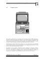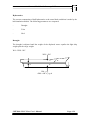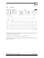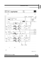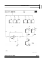
1
Doc.no.SO-0603-A/9 January, 1997 Cargo Handling Trainer CHT2000-VLCC-II-ws USER’S MANUAL Department/Author: Approved by: ___________________ <Aksel D.Nordholm> ____________________ <Harald Kluken> 2000 KONGSBERG NORCONTROL AS All rights reserved No part of this work covered by the copyright hereon may be reproduced or otherwise copied without prior permission from KONGSBERG NORCONTROL AS CHT2000-VLCC-II-ws User’s Manual Doc.no.SO-0603-A/9 January, 1997 DOCUMENT STATUS Issue No. SO-0603-A Date/Year 9 January, 1997 Inc. by ADN/td Issue No. Date/Year Inc. by CHANGES IN DOCUMENT Issue No. A ECO No. Paragraph No. CHT2000-VLCC-II-ws User’s Manual Paragraph Heading/ Description of Change First issue. Page i Doc.no.SO-0603-A/9 January, 1997 TABLE OF CONTENTS Section Page 1. 1.1 1.2 1.3 1.4 INTRODUCTION......................................................................................... 1-1 Concept Description ................................................................................ 1-2 System Description .................................................................................. 1-3 Simulator Configuration........................................................................... 1-4 Simulator Concept ................................................................................... 1-5 2. 2.1 2.2 TECHNICAL SPECIFICATION...................................................................... 2-1 Workstation HP 9000 / 425e.................................................................... 2-1 Server HP C 3020 T ................................................................................ 2-1 3. 3.1 3.2 3.3 3.4 INSTALLATION .................................................................................... 3-1 Introduction............................................................................................. 3-1 Storage Requirements .............................................................................. 3-1 Environmental Requirements.................................................................... 3-2 Main Power Requirements ....................................................................... 3-3 4. 4.1 4.2 4.2.1 4.2.2 4.3 4.4 4.5 4.5.1 4.5.2 4.5.3 4.5.4 4.5.5 4.5.6 4.5.7 4.5.8 4.5.9 4.5.10 4.5.11 4.5.12 4.5.13 4.5.14 4.5.15 4.5.16 4.5.17 FUNCTIONAL DESCRIPTION ....................................................................... 4-1 Introduction............................................................................................. 4-1 Computer System .................................................................................... 4-4 TEC2000 Instructor System.................................................................... 4-7 Fault System .......................................................................................... 4-27 Hull Models ........................................................................................... 4-27 Computerised Load Master.................................................................... 4-39 Model Description ................................................................................. 4-41 Cargo Bargraph ..................................................................................... 4-43 Cargo Survey......................................................................................... 4-44 Shear Force ........................................................................................... 4-45 Bending Moment ................................................................................... 4-47 Deflection .............................................................................................. 4-48 Stability Curve ....................................................................................... 4-49 Loading/Discharging .............................................................................. 4-50 Cargo Deck Lines .................................................................................. 4-51 Cargo Pump Room ................................................................................ 4-52 Cargo Bottom Lines............................................................................... 4-53 Cargo Line # 1....................................................................................... 4-54 Cargo Line # 2....................................................................................... 4-54 Cargo Line # 3....................................................................................... 4-55 Cargo Line # 4....................................................................................... 4-55 Ballast Line............................................................................................ 4-56 Slop Tanks and Oil Discharge Monitor................................................... 4-57 Centre Tank 1, 2, 3, & 4 Condition ........................................................ 4-58 CHT2000-VLCC-II-ws User’s Manual Page ii Doc.no.SO-0603-A/9 January, 1997 4.5.18 4.5.19 4.5.20 4.5.21 4.5.22 4.5.23 4.5.24 4.5.25 4.5.26 4.6 4.7 4.8 4.8.1 4.8.2 4.9 4.9.1 4.9.2 4.9.3 4.9.4 Wing Tank 1, 2, 4, 5 & 6 Port Condition................................................ 4-58 Wing Tank 1, 2, 4, 5 & 6 Stb. Condition ................................................ 4-58 Bunkers and Water Bargraph ................................................................. 4-59 Loading / Discharge / Ballast Routing .................................................... 4-60 Monitor ................................................................................................. 4-61 Boiler..................................................................................................... 4-64 Inert Gas Plant ....................................................................................... 4-65 Inert Gas Distribution. ........................................................................... 4-66 Cargo Oil Pump 1, 2, 3 & 4 and Separator ............................................. 4-67 MODELLING OF PUMP CHARACTERISTICS.................................. 4-69 Cargo Pumping Diagram........................................................................ 4-70 Oil/Gas Separator With Vacuum Pump .................................................. 4-71 Ballast Water Pump ............................................................................... 4-72 Pump Room Cross-over Lines / Stripping Pump / Eductor / Tank Cleaning Heater ..................................................................................... 4-73 Modelling of Stripping facilities.............................................................. 4-74 Tank Atmosphere .................................................................................. 4-75 Oil/Water Settling .................................................................................. 4-77 Liquid Tank temperature........................................................................ 4-78 Modelling of Residues............................................................................ 4-78 5. 5.1 5.1.1 5.1.2 5.2 5.2.1 5.2.2 5.2.3 5.3 5.3.1 5.3.2 5.3.3 5.4 5.4.1 5.4.2 5.4.3 5.4.4 5.4.5 5.4.6 5.4.7 5.4.8 5.4.9 5.4.10 OPERATION OF THE CHT2000-VLCC-II-WS ............................................. 5-1 TEC2000 Graphic Workstation................................................................ 5-2 Tracker-ball ............................................................................................. 5-2 Keyboard ................................................................................................. 5-2 Operating panels ...................................................................................... 5-3 Function buttons at the Instructor section................................................. 5-3 Alarm Section ........................................................................................ 5-15 Function buttons at the Operator section ................................................ 5-16 Cargo Handling Training from the Graphic Workstation......................... 5-21 Picture directory .................................................................................... 5-22 Picture Directory 2 LOAD MASTER .................................................... 5-23 General Operation.................................................................................. 5-25 Loading Procedure................................................................................. 5-42 Voyage Orders....................................................................................... 5-42 Planning Cargo Stowage........................................................................ 5-43 The Loading Plan................................................................................... 5-45 Deballasting ........................................................................................... 5-47 Lining up Pipelines and Valves ............................................................... 5-47 Setting P/V-valves ................................................................................. 5-49 Manifold Valve(s) .................................................................................. 5-49 Commencement of Loading ................................................................... 5-50 Monitoring Cargo Tanks........................................................................ 5-51 Changing Tanks ..................................................................................... 5-51 CHT2000-VLCC-II-ws User’s Manual Page iii Doc.no.SO-0603-A/9 January, 1997 5.4.11 5.4.12 5.4.13 5.5 5.5.1 5.5.2 5.5.3 5.5.4 5.5.5 5.5.6 5.6 5.6.1 5.6.2 5.6.3 5.6.4 5.6.5 5.6.6 5.6.7 5.6.8 5.6.9 5.6.10 5.7 5.7.1 5.7.2 5.7.3 5.7.4 5.7.5 5.7.6 5.7.7 5.7.8 5.7.9 5.7.10 5.7.11 5.7.12 5.7.13 5.7.14 5.7.15 5.7.16 5.8 5.8.1 5.8.2 5.8.3 5.8.4 5.8.5 Final Tank.............................................................................................. 5-52 Checks after Loading ............................................................................. 5-52 Laden Voyage........................................................................................ 5-52 Discharging Procedure........................................................................... 5-55 Operational Objectives ........................................................................... 5-55 Discharging sequence............................................................................. 5-55 Limiting Factors..................................................................................... 5-55 Discharge Plans...................................................................................... 5-57 Cargo Loss Control ............................................................................... 5-58 Instructions during and after Discharge .................................................. 5-59 Inerting Procedures................................................................................ 5-61 General .................................................................................................. 5-61 Inert Gas Policy .................................................................................... 5-62 Inerting Empty Tanks............................................................................. 5-63 Inerting during Deballasting ................................................................... 5-64 Inerting during COW and Water Washing .............................................. 5-64 Inerting during Loading ......................................................................... 5-65 Inerting during Discharging.................................................................... 5-65 Inert Gas purging prior to Gas Freeing ................................................... 5-65 Gas Freeing............................................................................................ 5-66 Inert Gas Emergency Procedure............................................................. 5-67 Ballasting............................................................................................... 5-69 Ballast Pump Ready ............................................................................... 5-70 Segregated Ballast ................................................................................. 5-75 Dirty Ballast (Departure Ballast) ............................................................ 5-76 Clean Ballast (Arrival Ballast ................................................................. 5-77 Stripping................................................................................................ 5-79 The Stripping Pump ............................................................................... 5-80 The Eductor........................................................................................... 5-81 The Vacuum Strip (Oil/Gas Separator.................................................... 5-82 Line Stripping ........................................................................................ 5-83 Slop....................................................................................................... 5-87 Double Slop Tank System...................................................................... 5-87 Filling the Port Slop Tank ...................................................................... 5-88 Separation in the Port Slop Tank............................................................ 5-88 Decanting the Port Slop Tank ................................................................ 5-89 Oil Discharge Monitor ........................................................................... 5-90 Oil Discharge Monitoring Variables ....................................................... 5-91 Inerting and Venting .............................................................................. 5-93 Start-up Procedures ............................................................................... 5-94 Shut down procedure............................................................................. 5-95 Inert/Vent .............................................................................................. 5-95 Inert Press/O2-content ........................................................................... 5-95 Distribution............................................................................................ 5-99 CHT2000-VLCC-II-ws User’s Manual Page iv Doc.no.SO-0603-A/9 January, 1997 5.8.6 5.9 5.9.1 Tank Atmosphere Pressure Control........................................................ 5-99 Tank Cleaning, Water and COW ............................................................ 5-99 Crude Oil Washing (COW) .................................................................. 5-101 CHT2000-VLCC-II-ws User’s Manual Page v Doc.no.SO-0603-A/9 January, 1997 CARGO HANDLING TRAINER CHT2000-VLCC-II-ws Chapter 1 Introduction CHT2000-VLCC-II-ws User’s Manual Doc.no.SO-0603-A/9 January, 1997 1. INTRODUCTION The last few years have seen the beginning of a drastic change in the education of ships officers. Due to new International and National Rules and Regulations the demand for more safe cargo handling has increased. At the same time new technology has made more advanced training simulators available at an affordable price. The purpose of Kongsberg Norcontrol´s Cargo Handling Trainer (CHT2000-VLCC-IIws) is to provide an educational tool that gives a realistic reproduction of the dynamic behaviour of a typical VLCC cargo handling system and reflects the interactions between the different auxiliary systems. A well- designed computerised simulator will, to a great extent, give the same training facilities, which means training in the normal operation of a shipís cargo handling system. In addition to giving the students operational training, CHT2000-VLCC-II-ws is also a tool for more intimate theoretical studies for loading/discharging operations, such as: - Planning the operations by using CHT2000-VLCC-II-ws as a load computer - Run test conditions on the loading computer - Studying single components - Studying tank atmosphere - Studying inert gas in relation to boiler load - Monitoring the discharge cost and time - Provide training in operations that the officers will have benefit of later on - Shows you the results of incorrect operations without damaging the equipment - Presents all relevant terminology and relates it to associated hardware - Demonstrates both theoretical aspects and practical results in one and the same room. CHT2000-VLCC-II-ws User’s Manual Page 1-1 Doc.no.SO-0603-A/9 January, 1997 1.1 Concept Description The CHT2000-VLCC-II-ws is based on the simulator design- and development- system, Operator Training Simulation System (OTISS) developed by Special Analysis and Simulation Technology Ltd. (SAST) UK. The Operator Man-Machine Interface (MMI) is realised using the EMULA Graphic software Package developed by Institutt For Energiteknikk (IFE) Halden, Norway. The CHT2000-VLCC-II-ws system is implemented on a network of Hewlett-Packard 9000 series computers. The structure of the system is outlined in the following illustration. By the simulation of faults and deteriorationís, the instructor can create a training situations that enables the trainee to meet and overcome these problems. This training environment will give the students experience in dealing with problems that would normally demand years of seagoing experience. The third part of the simulator is the instructorís station which includes the "simulator controls" for: Changing operational and ambient conditions Setting faults and deteriorationís, single or in series Simulate leaks in cargo lines and tank bulkheads Resetting faults Logging events and alarms General system communication The CHT2000-VLCC-II-ws is designed to train students in cargo handling operation under both normal and abnormal conditions. It is therefore of utmost importance that the training takes place in a realistic environment. To get a true impression of how to run cargo plant , the disturbing noise is essential, therefore KONGSBERG NORCONTROL has designed a unique synthesised audio system. Pump sounds are synchronised with the rpm of the cargo pumps and in addition the noises from diesel engines, generators, compressors, etc. are presented by separate sound amplifiers. CHT2000-VLCC-II-ws User’s Manual Page 1-2 Doc.no.SO-0603-A/9 January, 1997 1.2 System Description As pioneers in the ship automation field, KONGSBERG NORCONTROL Systems a.s., know how modern technology has improved safety, reliability and economy on board ship. The improvement has been immense, but it is also known that it is impossible to replace the proficiency and know how to an experienced engineer, the man who must be present in the right place at the right time to do things quickly and efficiently. KONGSBERG NORCONTROL Systems has designed a dynamic real-time computerised simulator which can compress years of experience into a few weeks, and provides hands-on training. The simulator provides the necessary information on dynamic and interactive processes as found in a real cargo plant. The CHT2000-VLCC-II-ws is designed to meet the demands for basic operational training of junior officers, fault studies with economy and optimisationís studies with the senior officers. It enables the simulation of individual auxiliary systems (sub-system) and independent components as well as an efficient simulated presentation of a total plant. KONGSBERG NORCONTROL Systems CHT2000 includes a comprehensive instructor communication link that allow him to: - Pre-program and store situations. - Develop and test new training programs. - Change operational and ambient conditions. - Freeze current situations for discussions and clarifications with the trainees. - Setting of single faults or automatic sequential fault. The CHT2000 has a layout and instrumentation typical to that of a modern vessel. CHT2000-VLCC-II-ws User’s Manual Page 1-3 Doc.no.SO-0603-A/9 January, 1997 1.3 Simulator Configuration The CHT2000 Simulator is implemented on a network of UNIX workstations with an Instructor Station used as a common server. The network is an Ethernet (protocol UDP/IP) and the server is equipped with a hard disk storage of 1.0 Gb. Data Tape Station is provided for taking back-up of the System Software Figure 1-1 Computer Configuration CHT2000-VLCC-II-ws User’s Manual Page 1-4 Doc.no.SO-0603-A/9 January, 1997 1.4 Simulator Concept The OTISS-/EMULA- environment is very flexible. The mathematical models and the man-machine interface are run as separate programs. The communication between them is established by UNIX sockets. The program running the mathematical models of the simulated process is called OTISS. The Man.Machine Interface program, EMULA, is driving the graphic pictures, and installed individually on each workstation. The OTISSprogram can run on any of the involved computers. When it is running on the server, the instructor can connect selected workstations for monitoring of the process by the students. When more than one EMULA station is connected to one OTISS program, the actions taken at one station will influence the shared process and the changes are observed on all the workstations. This way of running the simulator is controlled by the instructor to avoid chaos if different operators take inconsistent actions The simulator is run in one of two modes, as shown in figure 2. CHT2000-VLCC-II-ws User’s Manual Page 1-5 Doc.no.SO-0603-A/9 January, 1997 In the full simulation mode, the OTISS-program is run on the server, and the instructor can select each workstation in the workstation room to be connected to the simulation.. Man-Machine Interface Server HP-9000-705 Mathematical Models In part task simulation mode, the workstations are isolated from each other. The OTISS-program and the EMULA-program will run on each workstation. This mode is normally used for detailed studies of sub-systems of the simulator. Full Simulation Mode Each workstation is also capable of running the complete simulation model i.e. several workstations can control the simulation without interference with the others. Independent of what simulation mode is used, the workstations need access to the harddisk. Man-Machine Interface Mathematical Models Part Task Simulation Mode Figure 1-2 Simulator Concepts CHT2000-VLCC-II-ws User’s Manual Page 1-6 Doc.no.SO-0603-A/9 January, 1997 CARGO HANDLING TRAINER CHT2000-VLCC-II-ws Chapter 2 Technical Specification CHT2000-VLCC-II-ws User’s Manual Doc.no.SO-0603-A/9 January, 1997 2. TECHNICAL SPECIFICATION 2.1 Workstation HP 9000 / 425e The Hewlett Packard Workstations has the following specifications: HP-9000/425e Workstation Name Type 425e Description Processor MC68040 CPU Clock 25 Mhz Memory 16Mb ECC RAM (Error Control Correction) Monitor 16" Colour monitor Resolution 1280 * 1024 Interface SCSI and LAN Both plus 1 RS-232 Interface Performance 22 MIPS 2,6 MFLOPS Million Instructions pr.sec. Million floating point operations pr.sec. All data according to HP technical specification 2.2 Server HP C 3020 T The Host Computer (mathematical model computer) is a Hewlett Packard server. Together with distributed microprocessors it forms the complete trainer computer system. The microprocessors are located in workstatios and intelligently interfaced to the Host Computer via Ethernet Name Type C 3020 T Description Disc 1,0 Gb SCSL Hard Disc Back-up 2,0 Gb Digital Data Storage (Tape) All data according to HP technical specification CHT2000-VLCC-II-ws User’s Manual Page 2-1 Doc.no.SO-0603-A/9 January, 1997 CARGO HANDLING TRAINER CHT2000-VLCC-II-ws Chapter 3 Installation CHT2000-VLCC-II-ws User’s Manual Doc.no.SO-0603-A/9 January, 1997 3. INSTALLATION 3.1 Introduction The purpose of this chapter is to provide facility guide-lines for installation of the simulator. Consistent and reliable performance of the system is dependent on a proper environment including power conditioning, air flow, cooling and humidity control as well as installation of the system in conformance to standards. Achievement of these standards is mandatory for reliable operation and continued compliance with these standards is the basis for warranted performance. Specific requirements are provided for the computer and subsystems. These requirements are derived from several sources including manufacturers technical documentation, standard commercial practices, national and local building codes and regulation and most importantly, our experience in designing, constructing and operating simulator facilities. Additional information is included below as recommended guide-lines for the system. This information is based on experience gained from major simulator installations. 3.2 Storage Requirements The simulator equipment may be stored by the customer for a period up to 4 months. The following requirements has to be followed: Temperature : 0°C to +50°C Maximum Temperature Gradient : 15°C per hour Relatively Humidity : 5% to 90% no condensation The equipment must be kept in its original packing - unopened. The crates must not be stored on top of each other. Storage must take place indoors. CHT2000-VLCC-II-ws User’s Manual Page 3-1 Doc.no.SO-0603-A/9 January, 1997 3.3 Environmental Requirements Local climate conditions and the system configuration are essential to the requirements for heating, ventilation and air-conditioning. The heating ventilation and air conditioning system must provide a sufficient air flow with correct temperature and humidity. - Ideal temperature : 23°C± 3°C - Ideal relative humidity : 50% ± 10% - Dust : The air pressure in the simulator rooms should be higher than the pressure outside. Special demands are made on the air-conditioning units filter if the air includes corrosive gases, salts, conductive particles or other unusual particles of dust. Minimum and maximum requirements when in operation: - Minimum temperature : 10°C - Maximum temperature : 30°C - Relative humidity : 10% to 95% no condensation If the humidity is lower than 40%, there may be problems with static electricity. To ensure a reliable operation of the air-conditioning unit, preventive maintenance should be carried out regularly. A thermo-stat must be installed in the different rooms so the temperatures can be set individually. NOTE ! The Air - Conditioning equipment must include an automatic restart after a power failure. There is a requirement to maintain air-conditioning even if equipment is shut down, because parts of the system remain energized. If the humidity specifications are not maintained, condensation can accumulate causing damage to circuits when power is reapplied. CHT2000-VLCC-II-ws User’s Manual Page 3-2 Doc.no.SO-0603-A/9 January, 1997 3.4 Main Power Requirements Provisions are made for routing cables. Cable trays provides protection for the cables, shielding from electromagnetic interference and retaining access to the cables for maintenance. The modular nature of the simulator components dictates a large number of available power outlets. If possible, major components should be isolated from each other. For example, a fault in one room should not cause the loss of power in all rooms. Similarly, a failure in one room should not cause a power transient that would damage other parts of the computer system. Power conditioning is also important, especially if the local power sources do not provide the constant voltage and frequency required for system operation. Voltage spikes may be undetected and do no visible harm, when in fact the damage caused may be considerable and will only come to light as a serious failure later on. Then the cause may be difficult or impossible to determine. To avoid serious system failures an uninterrupted power supply (UPS)should be installed The Main supply to the electronic equipment should be taken from the buildings supply. main The main supply cable should be protected from lightning by varistors. All circuits should be protected by slow blow automatic circuit breakers. Voltage 230 V AC± 15 V AC RMS Single phase Frequency 50 Hz ± 0,5 Hz Permitted Voltage Fluctuation For duration of 5ms : For duration of 30m : +20% or -10% of normal phase voltage +15% of normal phase voltage Permitted Amplitude Distortion The momentary voltage may not differ more than 6% from a sinusiod voltage of the same RMS voltage Start Current CHT2000-VLCC-II-ws User’s Manual Page 3-3 Doc.no.SO-0603-A/9 January, 1997 - Up to 5 times normal current dependent on the configuration. The start current may vary from 10 ms to 10 seconds dependent on the configuration. Power Consumption Up to 3,5 kVA is required to run a full scale simulator. CHT2000-VLCC-II-ws User’s Manual Page 3-4 Doc.no.SO-0603-A/9 January, 1997 CARGO HANDLING TRAINER CHT2000-VLCC-II-ws Chapter 4 Functional Description CHT2000-VLCC-II-ws User’s Manual Doc.no.SO-0603-A/9 January, 1997 4. FUNCTIONAL DESCRIPTION 4.1 Introduction The modelling of this Cargo Handling Trainer CHT2000-VLCC-II-ws is based on the following Vesselís particulars: M.T. "Polar Lady" Loa Lpp Breadt moulded Depth moulded Summer draught CB Displacement,summer draught DW, summer draught 305.00 m 295.00 m 47.00m 30.40m 19.07m 0.801 217,552 tonnes 187,997 tonnes Cargo tanks: CT. # 1 CT. # 2 CT. # 3 CT. # 4 Net. volume(CBM) 30,813 30,818 30,818 30,806 LCG(m) 235.23 182.46 129.72 76.98 VCG(m) 12.69 12.68 12.68 12.68 WT. # 1 P+S WT. # 2 P+S WT. # 4 P+S WT. # 5 P+S SL.TK P+S 25,106 18,564 29,024 17,604 8,048 232.90 191.93 129.73 86.85 60.53 13.22 12.64 12.64 13.12 14.64 Net. volume(CBM) LCG(m) VCG(m) 12,113 10,460 276.19 165.62 13.99 12.63 Segregated Ballast Tanks: FP WT. # 3B P+S CHT2000-VLCC-II-ws User’s Manual Page 4-1 Doc.no.SO-0603-A/9 January, 1997 HFO. Tanks: HFO. FWD HFO. TK. AFT Net. volume(CBM) LCG(m) VCG(m) 3,800 3,800 263.86 48.51 13.41 13.96 Cargo Pumps: No. of set Capacity 4 Centrifugal Type Cargo Pumps 4,000 cbm/h 120 mLC Oil/Gas Separators: No. of set 4 Gas/Oil Separators Stripping Pumps: No. of set Capacity 1 Reciprocating Stripping Pump 350 cbm/h Stripping Eductor: No of set Capacity 1 Stripping Eductor 1500 cbm/h Ballast Pump: No, of set Capacity 1 Centrifugal Type Ballast Pump 4,000 cbm/h 120 mLC Cargo Lines: No. of set Size CHT2000-VLCC-II-ws User’s Manual 4 segregated cargo lines Page 4-2 Doc.no.SO-0603-A/9 January, 1997 Ballast Line: No of set Size 1 segregated ballast line P/V Valves: No. of set Range CHT2000-VLCC-II-ws User’s Manual One for each tank - 0.45 - 0.45 mWC Page 4-3 Doc.no.SO-0603-A/9 January, 1997 4.2 Computer System The graphic workstations are in principle used for running general UNIX applications. However, UNIX is concealed in the simulator as soon as the operator has logged in. The work stations will thereafter be operated in a graphic man-machine-interface in a "point and click" fashion by using a dedicated operational keyboard and a roller ball. On the operator stations, the operator/student(s) can view mimic pages representing the various simulated systems. These graphic mimic process diagrams are interactive, i.e. the process can be both monitored and controlled. In principle, all the graphic workstations can be configured as instructor stations. Whenever a workstation is going to be used in part task mode, the student using it will act as his own instructor, meaning that he will have the instructorís privilege to start/pause the simulation. Each individual can run the exercise at his own pace. CHT2000-VLCC-II-ws User’s Manual Page 4-4 Doc.no.SO-0603-A/9 January, 1997 The pushbuttons on the operational keyboard are grouped together in logically arranged clusters. All the instructor functions are located on the left side of the keyboard. The keyboards have a key, with which the instructor can prohibit student(s) access to the instructor functions on the keyboard. The following pages comprises a functional description of the main cargo handling systems and related sub-systems. The process diagrams with corresponding information such as temperature, flow, pressure, set points, etc. are presented on the colour graphic workstation. Additional diagrams and information giving insight to the simulated models are available and can be addressed by using the functional keyboard. The Process Diagrams presented have the following colour code for pipelines: - Light Blue: Blue: Green: Yellow: Brown: Orange: Pink: Steam Fresh Water Sea Water Diesel Oil Fuel Oil Cargo Vapour The Cargo lines have the following colour code: - Green: Yellow: Brown: Red: Line no. 1 Line no. 2 Line no. 3 Line no. 4 CHT2000-VLCC-II-ws User’s Manual Page 4-5 Doc.no.SO-0603-A/9 January, 1997 The Process Diagrams comprises abbreviations such as, T, G, P etc. meaning: T: G: P: N: Q: I: U: F: E: V: L: X: Z: W: c: d: H: M: R: Temperature Flow Pressure Rpm Force Ampere Voltage Frequency Electrical Power Valve Level Position Signal/Concentration Viscosity Constant Density Heat Transfer Mass Pump, Fan Status CHT2000-VLCC-II-ws User’s Manual Page 4-6 Doc.no.SO-0603-A/9 January, 1997 4.2.1 TEC2000 Instructor System CHT2000-VLCC-II-ws User’s Manual Page 4-7 Doc.no.SO-0603-A/9 January, 1997 The instructor system is equipped with a TEC2000 keyboard. The keyboard includes a normal QWERTY keyboard, Instructor section, Alarm section and Operator section . For detailed information see TEC2000 Instructor Manual. Trackerball: On the TEC2000 is a trackerball with 3 buttons on top.Trackerball moves cursor on the screen. Function of left button is: START pump/compressor or OPEN valve. Centre button to operate screen BUTTONS or to open display windows. Right button is opposite of left, namely STOP pump/compressor or CLOSE valve. Function buttons: INSTRUCTOR KEY OPERATOR Chooses between operator / instructor status. One push on the desired button will change status. When key is LOCKED, changing of operator status is not possible. Key locks when turned CLOCKWISE. CHT2000-VLCC-II-ws User’s Manual Page 4-8 Doc.no.SO-0603-A/9 January, 1997 INSTRUCTOR In Op OPERATOR SCENARIO INIT. COND. DIRECTORY OPERATION CONDITIONS MALFUNC. EDITOR ACTIONS EDITOR SOUND TIME EDITOR EVENTS EDITOR SNAPSHOT EVALUATION EDITOR REPLAY SNAPSHOT DIRECTORY RUNNING FREEZE STOP Scenario: Displays different scenarios to be used during simulation classes. Active in instructor mode only. Instructor: To create a scenario, enter scenario by pressing SCENARIO button. Prompts on screen will guide you onwards. Push software button CREATE, and click on a scenario button where you want it placed. (S01 to S20) After prompt and typing of scenario name, press enter. When entered name "attaches" to button, scenario is accepted. A prompt will then ask for an INITIAL condition to obtain parameters from. Type in initial condition I01 to I60, and press enter. If accepted, prompt line will add initial conditions name and change colour. When using instructors key pad (left side group of buttons), all the other available pages in editor are visible in top right corner of picture. Clicking on any of these CHT2000-VLCC-II-ws User’s Manual Page 4-9 Doc.no.SO-0603-A/9 January, 1997 software buttons will bring you to this picture, as would pressing any of same hardware buttons. CHT2000-VLCC-II-ws User’s Manual Page 4-10 Doc.no.SO-0603-A/9 January, 1997 INSTRUCTOR In Op OPERATOR SCENARIO INIT. COND. DIRECTORY OPERATION CONDITIONS MALFUNC. EDITOR ACTIONS EDITOR SOUND TIME EDITOR EVENTS EDITOR SNAPSHOT EVALUATION EDITOR REPLAY SNAPSHOT DIRECTORY RUNNING FREEZE STOP Init Conditions Directory: Displays recorded initial conditions. Active in instructor mode only. Instructor: To create an initial condition, "play" until desired running status is obtained. This is done in the same fashion as running an actual plant. Opening valves and starting pumps until a stable running condition on different levels is achieved. When satisfied with simulator situation, chose display INITIAL CONDITION and click on CREATE. Type in name of condition and press enter. When various levels of complexity have been recorded, these initial conditions can be run under scenario to create realistic simulations of actual on board situations with the assistance of malfunction editor and scenarios. To load an initial condition, click with centre trackerball button on chosen condition. Loading of initial condition in FREEZE mode only. CHT2000-VLCC-II-ws User’s Manual Page 4-11 Doc.no.SO-0603-A/9 January, 1997 Operating Conditions: Sets the response to actions during simulation. Active in instructor mode only. Instructor: Picture is divided into 9 windows where parameter responses can be set. - Access Different access levels can be set. Ordinarily only instructor can access OPERATION CONDITIONS to establish simulation parameters. - Fixed process Instructor can set some systems in permanent no alarms condition. Useful when sub systems are to be simulated without disturbances. - Inhibit keyboard buzzer Toggles buzzer sound active / inactive. - Levels Sets simulator response time constant for tank levels. Choose between three levels, slow to very fast. CHT2000-VLCC-II-ws User’s Manual Page 4-12 Doc.no.SO-0603-A/9 January, 1997 INSTRUCTOR - In Op OPERATOR SCENARIO INIT. COND. DIRECTORY OPERATION CONDITIONS MALFUNC. EDITOR ACTIONS EDITOR SOUND TIME EDITOR EVENTS EDITOR SNAPSHOT EVALUATION EDITOR REPLAY SNAPSHOT DIRECTORY RUNNING FREEZE STOP Dynamic response Sets simulator time response constant for controllers. - Ship dynamics Will change ship dynamic response time constant. - Log printer 1 Determines which events or alarms to be logged on printer. All five buttons can be activated simultaneously. Snapshot column: Whenever simulator creates a simulation snapshot, this will be placed here for later retrieval. Snapshots enter under a button with inserted time when snapshot was made. Snapshots can be auto generated with push button snapshot intervals. When pushed, page will prompt for intervals between snapshots. Note: Snapshot will only be visible when the simulation is started from the same initial conditions. Malfunction Editor: Allows editing of malfunctions during simulation. CHT2000-VLCC-II-ws User’s Manual Page 4-13 Doc.no.SO-0603-A/9 January, 1997 Only possible from INSTRUCTOR MODE. CHT2000-VLCC-II-ws User’s Manual Page 4-14 Doc.no.SO-0603-A/9 January, 1997 Instructor: A scenario with an initial condition must be available and chosen. This will be indicated on pictures right side. To create, click on software button CREATE and click on one of the buttons M01 to M40 and type in chosen name. IMPORTANT: When a malfunction name has been typed and ENTERED, a prompt will ask you which TAG name is wanted. THIS TAG NAME MUST BE WRITTEN WITH FULL STYLE NAME AND NUMBER DIRECTLY COPIED FROM MALFUNCTION LIST. IN ADDITION TYPE IN EITHER _S OR .S. OTHERWISE TAG WILL NOT ENTER. WHEN PROMPT CHANGES COLOUR, IT WILL BE WRITTEN F.EX. M0201_S , AND YOU ARE ALLOWED TO CONTINUE. In section VALUE, active and passive values are entered. When prompted, type in values either digital (0,1,2 etc.) or analog in percentage of max values. CHT2000-VLCC-II-ws User’s Manual Page 4-15 Doc.no.SO-0603-A/9 January, 1997 INSTRUCTOR In Op OPERATOR SCENARIO INIT. COND. DIRECTORY OPERATION CONDITIONS MALFUNC. EDITOR ACTIONS EDITOR SOUND TIME EDITOR EVENTS EDITOR SNAPSHOT EVALUATION EDITOR REPLAY SNAPSHOT DIRECTORY RUNNING FREEZE STOP ACTIVE Value entered is value when fault is activated. Either one triggered as one continuos fault or as repeating fault. PASSIVE Value entered is starting level. That is condition of operation before fault is activated. UNIT Engineering unit or percentage. Not necessary to be entered. AUTOMATIC MODE: Activating this will make fault go active, and stay active, when entered time is reached. Activating this button will make fault go active, and then off again when time limits entered are reached. Activated, this button will make fault go on and off repeatedly within specified time limits, as long as scenario is run. CHT2000-VLCC-II-ws User’s Manual Page 4-16 Doc.no.SO-0603-A/9 January, 1997 When activated, time ramp for fault to develop can be specified. Common for all four function buttons are that faults can be simulated after entering a scenario only when buttons are activated. When active, buttons change colour. Ramp function can be active together with any of three other buttons. To activate click on buttons with centre trackerball button. On the bottom half of screen (buttons A41 to A80) is event malfunctions. Used and created as malfunction, but triggering actions instead of malfunctions. Such as closing of valves. CHT2000-VLCC-II-ws User’s Manual Page 4-17 Doc.no.SO-0603-A/9 January, 1997 INSTRUCTOR In Op OPERATOR SCENARIO INIT. COND. DIRECTORY OPERATION CONDITIONS MALFUNC. EDITOR ACTIONS EDITOR SOUND TIME EDITOR EVENTS EDITOR SNAPSHOT EVALUATION EDITOR REPLAY SNAPSHOT DIRECTORY RUNNING FREEZE STOP Action Editor: Allows editing of actions, i.e. somebody stopping a pump unintentionally.. Active in instructor mode only. Using and creating actions as malfunction editor. Input of tag names similar to malfunctions editor, adding period S or underscore S after tag. When starting a scenario, wanted malfunctions and action to be performed during simulation must be chosen by clicking on software buttons. Changing colours will indicate which buttons are activated. In front of each buttons is a light with 2 circles. Inner circle lit means that READING is active, meaning set intervals are reached, and action started. Outer circle lit means action is activated, but waiting for set time interval to be reached in order to switch action on. Time Editor: Allows editing of response time. Active only in instructor mode. CHT2000-VLCC-II-ws User’s Manual Page 4-18 Doc.no.SO-0603-A/9 January, 1997 INSTRUCTOR In Op OPERATOR SCENARIO INIT. COND. DIRECTORY OPERATION CONDITIONS MALFUNC. EDITOR ACTIONS EDITOR SOUND TIME EDITOR EVENTS EDITOR SNAPSHOT EVALUATION EDITOR REPLAY SNAPSHOT DIRECTORY RUNNING FREEZE STOP Instructor: Clicking on CHANGE TIMEPHASE software button enters a line on time section of picture. Using inner scroll buttons to locate change line between actions or events to be changed. Then outer scroll buttons to change time phase. Event Editor: Active in instructor mode only. Allows editing of events, meaning specific actions or malfunctions to be initiated in proper sequence. Snapshot: Takes a snapshot of simulation for later reference. Places snapshot in snapshot directory with time/date reference. Active only in instructor mode. CHT2000-VLCC-II-ws User’s Manual Page 4-19 Doc.no.SO-0603-A/9 January, 1997 Evaluations Editor: For evaluations of student response during simulation. Active in instructor mode only. Input of specified measuring variables under tag name. Specify upper and lower limits. Will evaluate how process is kept by student during simulation. Evaluation criteria is whether student is able to maintain process within specified limits. Running: Starts simulation after init. conditions or freeze. Active only in instructor mode. When RUNNING button is pushed, a prompt will inform that simulation is started. Freeze: Freezes simulation during breaks or when situation needs time-out for evaluation. Active only in instructor mode. When FREEZE button is pushed, a prompt will inform that simulation is halted. CHT2000-VLCC-II-ws User’s Manual Page 4-20 Doc.no.SO-0603-A/9 January, 1997 INSTRUCTOR In Op OPERATOR SCENARIO INIT. COND. DIRECTORY OPERATION CONDITIONS MALFUNC. EDITOR ACTIONS EDITOR SOUND TIME EDITOR EVENTS EDITOR SNAPSHOT EVALUATION EDITOR REPLAY SNAPSHOT DIRECTORY RUNNING FREEZE STOP Stop: Ends simulation after a prompt. Pressing STOP and typing yes after prompt will log out of simulator completely. Active in both modes. To restart: Type LOGIN and press ENTER. Type sim in both login name and password. Remember to press ENTER after each input. Select one of offered options. Load initial condition by pressing selected condition button. Initial condition found in INITIAL CONDITIONS DIRECTORY. CHT2000-VLCC-II-ws User’s Manual Page 4-21 Doc.no.SO-0603-A/9 January, 1997 1 2 3 4 5 6 7 8 9 10 11 12 13 14 15 16 17 18 19 20 21 22 23 24 25 26 27 28 ALARMS Alarm Pages: Pushing one of the buttons marked 1 to 28 will display a window on screen with system tag information. List is divided into several columns. CHT2000-VLCC-II-ws User’s Manual Page 4-22 Doc.no.SO-0603-A/9 January, 1997 MALFUNC. LIST VARIABLE LIST ALARM LIST PICTURE DIRECTORY MARK PICTURE PREVIOUS PICTURE SELECT PICTURE RECALL MARKED P. NEXT PICTURE ALARM ACKN ALARM LOG ALARM SILENCE Malfunction List: Displays window with possible malfunctions directory page. When main system is recognised, a click on system button displays system list. List can be scrolled or removed with cursor and centre trackerball button. Active in both modes. Operator: Push button MALFUNCTION LIST, and select subsystem by clicking on this. Clicking on system will activate second window with system variables. After location of suspected fault, click on this lines COLON with RIGHT tracker ball button. A prompt will identify tag, and that a repair attempt is made. CHT2000-VLCC-II-ws User’s Manual Page 4-23 Doc.no.SO-0603-A/9 January, 1997 Instructor: As in operator mode, but additional information displayed. Clicking on selected lines COLON with LEFT trackerball button will toggle faults ON / OFF. When a fault is selected ON, it will change colour, and thus be identifiable. Far right of each line is a numeric value in percentage. Clicking on this with centre trackerball button will allow entering rate of wear for component. Selecting 100% rate of wear will render component useless instantaneously. When a fault is selected ON, the system picture will have the M button in lower left corner lighted in yellow. Student , in operator mode, will not have this indication of active faults. Variable List: Displays window with list of variables directory. After recognising main system, clicking on system button displays list of variables for this system. List can be scrolled, moved or removed with centre button on trackerball and cursor. Instructor: After pushing VARIABLE LIST, identify sub system and press selected system. Displayed window will then be identical to that mentioned in alarm pages. Tag details and measured values will be displayed. Displayed data can be changed after clicking on values with centre trackerball button. After typing in new values, and pressing enter, new data entered will gradually return to measured values. Selecting upper / lower alarm limits, and entering new data will permanently reset limits. CHT2000-VLCC-II-ws User’s Manual Page 4-24 Doc.no.SO-0603-A/9 January, 1997 MALFUNC. LIST VARIABLE LIST ALARM LIST PICTURE DIRECTORY MARK PICTURE PREVIOUS PICTURE SELECT PICTURE RECALL MARKED P. NEXT PICTURE ALARM ACKN ALARM LOG ALARM SILENCE Operator: Read only, no actions or changes possible. Alarm List: Displays window with alarm page directory. After recognition of system, clicking on system displays list of alarms in this system. List can be scrolled, moved or removed with cursor and centre trackerball button. Instructor: After pressing on ALARM LIST and identifying sub system, window with list of alarms will be displayed. Picture Directory: Displays list of system pictures. After recognition of system, and clicking on this, system picture will display on screen. CHT2000-VLCC-II-ws User’s Manual Page 4-25 Doc.no.SO-0603-A/9 January, 1997 Mark Picture: Clicking on this will mark picture for later recollection with RECALL MARKED PICTURE. After clicking MARK PICTURE, enter a chosen number. After clicking RECALL MARKED PICTURE, enter chosen number. Select Picture: Allows selection of picture after writing picture name in prompt. Enter two letters and two digits without space. Previous Picture:/Next Picture: Allows scrolling to next/previous picture in line as listed in picture directory. Alarm Acknowledge: Acknowledges external lights. Alarm Log: Displays active alarms. To acknowledge all alarms displayed at once, press EXTENDED CHAR button and A simultaneously. Alarm Silence: Shuts off alarm sound. CHT2000-VLCC-II-ws User’s Manual Page 4-26 Doc.no.SO-0603-A/9 January, 1997 4.2.2 Fault System A comprehensive selection of malfunctions are available through the fault system. Each sub-system is provided with a large number of malfunctions. These are selectable from the Instructor Station during full simulation mode, and from each workstation when in part task mode. The pages in chapter 7 show the choice of malfunctions which can be introduced. The two first pages comprises the Directory List, while the rest of the pages contain the malfunctions available. 4.3 Hull Models The content of liquid in the tanks will have an inevitable impact on the hull condition in terms of: - Hydrostatic conditions Draft Heel Trim - Intact stability: Meta-centre height - Hull Strain: Shear force Bending moment Hull deflection These parameters are continuously computed based on currently updated tank levels and liquid densities. In addition, manually entered data will be computed and updated. CHT2000-VLCC-II-ws User’s Manual Page 4-27 Doc.no.SO-0603-A/9 January, 1997 Basic hull design Based on outline specification on main geometrical data the following items have been computed: - Hydrostatics - Loading conditions: Light ship condition with: Intact stability Shear force distribution Bending moment distribution - Ballast condition with: Intact stability Shear force distribution Bending moment distribution - Full load condition with: Intact stability Shear force distribution Bending moment distribution - Longitudinal strength including limit values for: Shear forces Bending moments Moment of inertia Bonjean tables CHT2000-VLCC-II-ws User’s Manual Page 4-28 Doc.no.SO-0603-A/9 January, 1997 Hydrostatics The current computation of hull hydrostatics at the actual load conditions is made by the hull simulation models. The following parameters are computed: - Draught - Trim - Heel Draught The draught is adjusted until the weight of the displaced water equalise the light ship weight plus the cargo weight. Wd = WLS +WC WLS + WC G B dt AW T Wd = ρ g dWd =AW ∀ ρ g dt CHT2000-VLCC-II-ws User’s Manual Page 4-29 Doc.no.SO-0603-A/9 January, 1997 Change in draught due to change in cargo When the weight of the cargo is changed the draught will be changed accordingly. The change in draught can be estimated from the formula for displacement (Tons) Per. Cm draught: δWD = ρAW * 0.01(Tons/Cm) This can be found in the tables and curve sheet for the hydrostatics. W D dWD t T Trim Trim is adjusted until the trimming moment is equalised by the buoyancy moment from the displaced water. The trimming moment is calculated for the Longitudinal Centre of Flotation (LCF), and the trimming is made at this point. The location of the LCF is given by the shape and area of the hull's water-plane at the actual draught, as the total longitudinal moment of water-plane area is to be equal to zero at the LCF. L ?x dAW =0 0 M g 1 F a CHT2000-VLCC-II-ws User’s Manual WL1 WL 0 S Page 4-30 Doc.no.SO-0603-A/9 January, 1997 Change in the trim The amount of trimming can be estimated by means of the Moment To Trim 1 Cm (MTC). formula: δMT = ρ IL L This can be found in the hydrostatics tables. a t A M 1g F t WL 2 tF WL AP CHT2000-VLCC-II-ws User’s Manual 1 FP Page 4-31 Doc.no.SO-0603-A/9 January, 1997 Heel The heel is adjusted until the heeling moment is equalised by the buoyancy moment of the displaced water. The heeling will always take place along the longitudinal centre line. L LCF x B(x) dx Water - plane area L AW = ? dAW 0 L = 0 ? B(x) dx Water - plane moment of area (longitudinal) L FL = ? xdAW 0 L = 0 ? B(x)x dx Water moment of inertia (longitudinal) L L 2 IL = ? x dAW = 0 0 ? B(x)x2 dx CHT2000-VLCC-II-ws User’s Manual Page 4-32 Doc.no.SO-0603-A/9 January, 1997 Intact Stability G B K As long as the vessel lies in upright position there will always be an equilibrium between the weight forces (light ship + cargo) acting through the gravity centre, G, and the total buoyancy forces acting through the buoyancy centre, B, G and B will always be located on the same vertical line at a distance of KG and KB from the keel respectively. M φF = M φ G Z x B K dx X B´ ∆ργ When the ship is inclined due to a heeling moment, the buoyancy centre will move to a new position, B, due to the change in the displacement's volume and shape. The vertical line through b will cut the ship centre-line at an angle, 0, in the point M. At small angles of heeling point M is called the Initial Meta Centre. CHT2000-VLCC-II-ws User’s Manual Page 4-33 Doc.no.SO-0603-A/9 January, 1997 The horizontal distance between the centre and gravity, G, and the vertical line through the new centre of buoyancy, B, is denoted GZ and represents the arm of the rectifying moment. At small angle of heeling (which normally will be the case) GZ = GM sinθ The total rectifying moment counteracting the heeling will then be: Μ = ρ gVD* GM sinθ Thus: When GM > 0 -> M > 0 I.e: The heel will be counteracted and the ship is said to be stabilised. When GM = 0 -> M = 0 I.e: The heel will remain and the ship is said to be indifference. When GM < 0 -> M < 0 I.e: The heel will increase and the skip will be unstable. The considerations above are based on the height, GM, which is called the Meta Centre Height. GM = KB - KG (ref. fig Ship Heeling) GM = KB + BM - KG GM = KB + I/VD - KG Where: I = VD = The waterplane´s longitudinal moment of inertia at the actual draught. The volume displacement at the actual draught. I = CILBT3 Then: CHT2000-VLCC-II-ws User’s Manual Page 4-34 Doc.no.SO-0603-A/9 January, 1997 GM = KB + C1 * B3 / CB * T- KG CHT2000-VLCC-II-ws User’s Manual Page 4-35 Doc.no.SO-0603-A/9 January, 1997 Load distribution The relationship between the load distribution, the shear force, the bending moment and the deflection can preferably be illustrated by considering a straight beam with an even load, q0 Y L 0 X The relationship between the load distribution, and the shear force, the bending moment and the deflection can then be expressed as follows: The load distribution: (1) q0 = EI d4y / dx4 The shear force: (2) -Q = EI d3y / dx3 = q0 x + C1 The bending moment: (3) -M = EI d2y / dx2 = q0x2 / 2 + C1x + C2 The inclination: (4) EI dy / dx = q0 x3 / 6 + C1 x2 / 2 + C2x + C3 CHT2000-VLCC-II-ws User’s Manual Page 4-36 Doc.no.SO-0603-A/9 January, 1997 The deflection: (5) EI y = q0 x4 / 24 + C1 x3 / 6 + C2 x2 / 2 + C3 + C4 Where: The integration constants will be dependent on the actual support of the beam and has to be decided in each particular case. Example: A beam with even load and free supports in both of the ends will have the following relationship between load distribution, shear force, bending moment, including and deflection. q q B L Q + 1 2 - 2 Q + ξ qI qI 2 8 + - qI 3 χ EI Y Y max = 5qI 4 384 EI CHT2000-VLCC-II-ws User’s Manual Page 4-37 Doc.no.SO-0603-A/9 January, 1997 The Ship's Hull The ship's hull will differ from an even loaded beam in two ways: - The load distribution will not be even throughout the hull. - The cross section area and the corresponding moment of inertia will vary along the hull. The load distribution along the hull will be: q q1s qc qb = = = = (q1s + qc) - qb Distributed weight, light ship. Distributed weight, cargo. Distributed buoyancy. A simple example on the relationship between the load distribution, the shear force and bending moment is shown on the figure below. M M q 0 q L 2 + + - 0 - L 2 Q Q It is evident that a more detailed calculation of load distribution, shear force, bending moment and deflection for a ship's hull is rather complex and will require a computer program. The DataLoad programs included in the CHT2000 will continuously (i.e: approx. each 10th second) compute the parameters said on the current load condition related the ship's geometry and the hull's strength as stated in the computerised ship model of the Det norske Veritas, DnV. CHT2000-VLCC-II-ws User’s Manual Page 4-38 Doc.no.SO-0603-A/9 January, 1997 4.4 501 502 503 504 505 506 Computerised Load Master Cargo Bargraph (Load Master) Cargo Survey (Load Master) Shear Force (Load Master) Bending Moment (Load Master) Deflection (Load Master) Stability Curve (Load Master) 601 Misc. Tanks (Load Master) 100 CHT2000-VLCC-II-ws User’s Manual Directory 1 Page 4-39 Doc.no.SO-0603-A/9 January, 1997 The purpose of the Computerised Load Master is to avoid excessive bending stresses in the hull structure. These stresses vary with the cargo distribution throughout the length of the ship. Incorrect loading can damage the ship and hence the cargo/ballast must be placed according to a carefully calculated plan. It is, however, impossible to foresee all possible cargo distributions. It is therefore necessary to have an easy-to-handle computer on board which can calculate all the appropriate stresses for every load distribution case. In addition to the current data on draft, trim and heel, the Load Master also calculates the following, based on manual input: - Hydrostatic conditions (draft, trim) - Intact stability (FS; GM; GZ) Meta Centric height. - Longitudinal strain (shear force; bending moment; hull deflection) - Relative tank content The output from the Load Master is displayed on the variable pages. The shear force, bending moment, hull deflection and stability curve can be screen dumped to the printer. CHT2000-VLCC-II-ws User’s Manual Page 4-40 Doc.no.SO-0603-A/9 January, 1997 4.5 Model Description 101 Cargo Bargraph 128 Wing Tank 4 Port Condition 222 102 Cargo Survey 129 Wing Tank 5 Port Condition 223 103 Shear Force 130 Wing Tank 6 Port Condition 224 104 Bending Moment 131 Wing Tank 1 Stb. Condition 225 105 Deflection 132 Wing Tank 2 Stb. Condition 226 106 Stability Curve 133 Wing Tank 4 Stb. Condition 227 107 Load/Discharge 134 Wing Tank 5 Stb. Condition 228 108 Cargo Deck Line 135 Wing Tank 6 Stb. Condition 229 109 Cargo Pump Room 201 Bunkers and Water Bargraphs 230 110 Cargo Bottom Lines 206 Load Discharge Ballast Routing 231 111 Line 1 207 Monitor 232 112 Line 2 208 Boiler 233 113 Line 3 209 Inert Gas Plant 234 114 Line 4 210 Inert Gas Distribution 235 115 116 Ballast Line Slop Tanks/Oil Discharge Monitor Center Tank 1 Condition Center Tank 2 Condition Center Tank 3 Condition Center Tank 4 Condition Wing Tank 1 Port Condition Wing Tank 2 Port Condition 211 212 Crude Oil Pump 1/separator Crude Oil Pump 2/separator 240 Cargo Pumping Diagram 213 Crude Oil Pump 3/separator 214 Crude Oil Pump 4/separator 215 Ballast Water Pump 300 216 Stripping Pump/Eductor/Cow/Sw 301 Description of Legend Pen Recorder 122 123 124 125 126 127 CHT2000-VLCC-II-ws User’s Manual 500 Center Tank 1 Atmosphere Center Tank 2 Atmosphere Center Tank 3 Atmosphere Center Tank 4 Atmosphere Wing Tank 1 Port Atmosphere Wing Tank 2 Port Atmosphere Wing Tank 4 Port Atmosphere Wing Tank 5 Port Atmosphere Wing Tank 6 Port Atmosphere Wing Tank 1 Stb. Atmosphere Wing Tank 2 Stb. Atmosphere Wing Tank 4 Stb. Atmosphere Wing Tank 5 Stb. Atmosphere Wing Tank 6 Stb. Atmosphere Directory 2 LOAD MASTER Page 4-41 Doc.no.SO-0603-A/9 January, 1997 The Directory will give the operator an overview of all process pictures. From this directory any picture can be selected including the Load Master directory. On the following pages you will find simplified drawings of the process pictures according to the directory. CHT2000-VLCC-II-ws User’s Manual Page 4-42 Doc.no.SO-0603-A/9 January, 1997 4.5.1 Cargo Bargraph Cargo Baragraph will give the operator a total view of the cargo- and ballast- tanks with information about tank level, flow rate, cargo density and quantity in each tank. CHT2000-VLCC-II-ws User’s Manual Page 4-43 Doc.no.SO-0603-A/9 January, 1997 4.5.2 Cargo Survey The Cargo Survey picture will give an overview of the ullage in the cargo-, ballast- and HFO- tanks. Ship conditions will be dynamic updated based on tank ullage. CHT2000-VLCC-II-ws User’s Manual Page 4-44 Doc.no.SO-0603-A/9 January, 1997 4.5.3 Shear Force CHT2000-VLCC-II-ws User’s Manual Page 4-45 Doc.no.SO-0603-A/9 January, 1997 The Shear Forces are calculated from the load distribution of the ship including the steel weights of the different hull sections, and the corresponding Buoyancy forms. The graphic picture will display three different curves. - The yellow curve shows maximum permitted shear forces in harbour condition. The red curve shows the maximum permitted shear forces in seagoing condition - The blue curve shows actual shear forces. The shear forces (P) in each section (0 -12) is expressed in Kilotonnes. Each value is equipped with an alarm that activates when the limit value is exceeded. The "frame number" is identical to the distance from aft perpendicular to tank section in meters. CHT2000-VLCC-II-ws User’s Manual Page 4-46 Doc.no.SO-0603-A/9 January, 1997 4.5.4 Bending Moment The Bending Moments are calculated from the Shear Force distribution. The graphic picture will display three different curves. The yellow curve shows maximum permitted bending moment in harbour condition. - The red curve shows the maximum permitted bending moment in seagoing condition - The blue curve shows actual bending moment. The bending moments (Q) in each section (0 - 12) is expressed in Kilotonnesmeter. Each value is equipped with an alarm that activates when the limit value is exceeded. Positive bending moments represents hogging condition and negative moments represents sagging condition. CHT2000-VLCC-II-ws User’s Manual Page 4-47 Doc.no.SO-0603-A/9 January, 1997 4.5.5 Deflection The hullís deflection (from the straight line) is calculated from the bending moments and from the elasticity of each hull section. The Deflection (L) in each section (0 -12) is expressed in Metres. Positive deflection represent a hogging hull condition, negative deflection represent a sagging hull condition. CHT2000-VLCC-II-ws User’s Manual Page 4-48 Doc.no.SO-0603-A/9 January, 1997 4.5.6 Stability Curve The stability curve in the form of righting arm values is computed for heel angles ranging from 0 to 10 degrees. From this the meta centric height is computed. All righting arm values are corrected (reduced) for possible "free surface" effects. The reduction in meta centric heights is specifically given (FS Red.). The area under the stability curve from 0 to 40 degrees representing the Dynamic stability is shown in meter radians (DS Rad). CHT2000-VLCC-II-ws User’s Manual Page 4-49 Doc.no.SO-0603-A/9 January, 1997 4.5.7 Loading/Discharging The picture gives information of shore terminal plant. The proper selection (loading/discharging) must be made prior to operation or by the instructor. The manifold connections port or starboard must be selected by clicking on the connecting flanges with the left mouse button. The pressure/flow characteristics of the terminal is set by the instructor, as well as cargo loading temperature and density. CHT2000-VLCC-II-ws User’s Manual Page 4-50 Doc.no.SO-0603-A/9 January, 1997 4.5.8 Cargo Deck Lines The vessel is equipped with 4 main liquid lines, each with a dedicated cargo pump. Depending of number of shore connections available in each scenario, cross connection on the manifold must be selected. From the deck manifolds on port or starboard side the cargo can be routed through pipelines and valves to cargo tanks, or from cargo tanks to pump room and manifolds. CHT2000-VLCC-II-ws User’s Manual Page 4-51 Doc.no.SO-0603-A/9 January, 1997 4.5.9 Cargo Pump Room By clicking the 109 button on the Cargo deck line mimic (MD108), direct access the Cargo Pump Room (MD 109) is obtained. An overall view of cargo pump room. Showing pump room with pumps/valves/lines for cargo- and ballast- handling. It also include the eductor, stripping pump, oil/gas separator tanks, and oil discharge monitoring (ODM) control valves. From this mimic the pump room routing is performed. Each major component as cargo pumps, ODM, stripping pump, eductor have buttons for easy access to next operating level. CHT2000-VLCC-II-ws User’s Manual Page 4-52 Doc.no.SO-0603-A/9 January, 1997 4.5.10 Cargo Bottom Lines Cargo Bottom Lines (MD 110) contains an overall view of line arrangement in cargoand ballast tanks. The system consist of 4 main cargo lines and 1 separate ballast line, all located in the centre tanks. The main cargo lines are interconnected via cross-over lines and isolating valves Cargo- and ballast- tanks are connected to the main lines via branch pipes and isolating valves. Main- and stripping - suctions (bell-mouths) are located in aft end of the tanks and relatively close to the longitudinal bulkheads in order to obtain maximum out-turn during discharging, stripping and COW’ing. CHT2000-VLCC-II-ws User’s Manual Page 4-53 Doc.no.SO-0603-A/9 January, 1997 4.5.11 Cargo Line # 1 Cargo line # 1 is, from the manifold, connected into CT. # 1 and WT. # 5 P&S via the pump room and cargo drop line # 1 and interconnected to line # 2 via branch line and isolating valve located in CT. # 1 From this mimic one will have a full overview of system no 1 during start-up of cargo operations. 4.5.12 Cargo Line # 2 Cargo line # 2 is, from the manifold, connected into CT. # 4 and WT. # 1 P&S via the pump room and cargo drop line # 2 and interconnected to line # 3 via branch line and isolating valve located in CT.2 #. From this mimic one will have a full overview of system no 2 during start-up of cargo operations. CHT2000-VLCC-II-ws User’s Manual Page 4-54 Doc.no.SO-0603-A/9 January, 1997 4.5.13 Cargo Line # 3 Cargo line # 3 is, from the manifold, connected into CT. # 3 , WT. # 2 P&S and WT. # 6 P&S via the pump room and cargo drop line # 3 and interconnected to line # 2 via branch line and isolating valve located in CT.2 #. From this mimic one will have a full overview of system no 3 during start-up of cargo operations. 4.5.14 Cargo Line # 4 Cargo line # 4 is, from the manifold, connected into CT. # 2 , WT. # 4 P&S via the pump room and cargo drop line # 4 and interconnected to line # 3 via branch line and isolating valve located in CT.2 #. From this mimic one will have a full overview of system no 4 during start-up of cargo operations. CHT2000-VLCC-II-ws User’s Manual Page 4-55 Doc.no.SO-0603-A/9 January, 1997 4.5.15 Ballast Line The ballast line is, from the pump room, connected into the segregated ballast tanks WT. # 3 P&S and FPT. A separate ballast deck line is fitted for ballasting CT. #2 - 4 and WT. # 2 - 5 P+S. via drop lines. CHT2000-VLCC-II-ws User’s Manual Page 4-56 Doc.no.SO-0603-A/9 January, 1997 4.5.16 Slop Tanks and Oil Discharge Monitor The slop system consist of two slop tanks with WT. #6P as primary slop tank and WT. #6S as secondary slop tank. A decanting (balance) line is connected between the two slop tanks and an equalising line connects WT. #6P to CT. #4. All dirty ballast discharge from cargo tanks is monitored by the ODM (Oil Discharge Monitor), as regarded by IMO regulation. Oil contaminated ballast with more than 15 PPM, will be directed to port slop tank as long as the measured oil content is too high. CHT2000-VLCC-II-ws User’s Manual Page 4-57 Doc.no.SO-0603-A/9 January, 1997 4.5.17 Centre Tank 1, 2, 3, & 4 Condition The centre tank picture gives a detailed description of the tank condition, including the total mass of water, oil or mixture in the tank. Inert gas flow, venting, washing, cow-ing, heating, loading and discharging will be shown in detail to the operator. There are installed a washing machine in each tank that can be programmed from MD 220. The washing machines are strategically placed in order to minimise shadow effect. Steam heating coils are fitted in the bottom of each tank and is operated by the cargo heating steam valve. 4.5.18 Wing Tank 1, 2, 4, 5 & 6 Port Condition The tank facilities is the same for port wing tanks as described for centre tanks. 4.5.19 Wing Tank 1, 2, 4, 5 & 6 Stb. Condition The tank facilities are the same for starboard wing tanks as described for centre tanks. CHT2000-VLCC-II-ws User’s Manual Page 4-58 Doc.no.SO-0603-A/9 January, 1997 4.5.20 Bunkers and Water Bargraph The fresh water tank and the DO/HFO tanks are auxiliary tanks that can be filled/emptied directly from this picture by changing the volume variable (Variable page 0074). Consumption of HFO on the boiler will be from HFO tank aft which reflect the transfer to the aux. tanks. During sea voyage one must transfer HFO from HFO tank fore by starting the transfer pump (Variable page 0073). CHT2000-VLCC-II-ws User’s Manual Page 4-59 Doc.no.SO-0603-A/9 January, 1997 4.5.21 Loading / Discharge / Ballast Routing Loading / Discharging / Ballasting Routing picture shows the operator how pipelines are routed from manifolds and sea chests into the cargo and ballast tanks. This picture is not dynamically updated. CHT2000-VLCC-II-ws User’s Manual Page 4-60 Doc.no.SO-0603-A/9 January, 1997 4.5.22 Monitor Information on the overall cargo handling performance display the : - Use of energy (pump/heating). - Amount of pollution (oil spill/hydro carbon/gas waist) - Efficiency of operation (manifold connection time). Economical Studies: The computer accumulates the power consumption during cargo handling operations such as loading, discharging, ballasting, crude oil washing etc. Power consumption can be measured as: - Steam consumption in tonnes. - Oil consumption in tonnes and USD. - Total energy consumption in MWh. CHT2000-VLCC-II-ws User’s Manual Page 4-61 Doc.no.SO-0603-A/9 January, 1997 This feature enables the students to carry out economical studies of the cargo handling operation thus improving cargo handling efficiency. Pollution Control: The simulator has an oil monitoring system which continuously measures all liquid pumped overboard. A preset limit for acceptable oil in the overboard liquid can be set by the operator assuring that no polluted liquid will be pumped overboard. The computer will accumulate the amount of oil pumped overboard and calculate the amount per nautical mile. Time Scale: Time factor is in Normal operating mode set to time factor 1 (Real time). From picture no 1000 (Operating condition) the dynamic response time can be selected. In Fast mode the dynamic response time will have time factor 5 and in Very fast mode the factor will be 20. Period: The simulation period will be the result of actual simulation time multiplied by the time factor from when the operating mode was selected. Ship state: The ship speed can be set from the Variable page 0003 (Sea/Ship state). During loading/discharging operations this should be set to zero. The speed will have effect on the HFO consumption, the trim, the cargo temperature and the ODM when in use. Weather condition: The weather condition is selected from the Variable page 0003 (Sea/Ship state). Condition is selected by entering wind force 0 - 12 after the beaufort scale. The weather condition will have influence on HFO consumption, trim and heel (rolling), shear forces, deflection and ullages in the tank with cavitation of pumps if cargo-transfer or COW operations is in progress. It will also have effect on the stratification (mixing) of oil and water in the tanks. Solar Time: The Solar time is automatically following the Period in a 24 hour cycle and will begin at zero if not manually selected otherwise. The solar time can be manually set in the Variable page 0003 (Sea/ship state). The Solar time will have influence on the vapour CHT2000-VLCC-II-ws User’s Manual Page 4-62 Doc.no.SO-0603-A/9 January, 1997 pressure in the cargo tanks based on the temperature leakage from day/night effect. CHT2000-VLCC-II-ws User’s Manual Page 4-63 Doc.no.SO-0603-A/9 January, 1997 4.5.23 Boiler The oil fired boiler is equipped with two steam atomising oil burners that can produce approximately 50 ton/hour steam at 15 bar and 410 oC. When the boiler is started it will automatically purge, ignite and open for fuel, regulate the water level etc. Steam consumers are steam driven pumps and heaters in cargo tanks. The flue gas from the boiler is also used for Inert Gas production. The boiler can be isolated from the variable page no 0081 (Steam boiler control data). This will allow all aux. systems to operate without the boiler active. CHT2000-VLCC-II-ws User’s Manual Page 4-64 Doc.no.SO-0603-A/9 January, 1997 4.5.24 Inert Gas Plant The cargo handling simulator is modelled with a steam boiler where flue gas is taken from the boiler uptake and directed through the scrubber, fans, and deck water seal to the main inert gas deck line. The capacity of the inert gas plant is approximately 40,000 cbm/h, provided sufficient flue gas is available from the boiler. Flue gas is produced by steam consumption to aux. systems. The scrubber washes and cools the flue gas in order to reduce soot and SO2 content. The oxygen content will variate with the boiler load. In order to avoid O2 exceeding 5% to enter the tank, an automatic valve will close and route the fluegas to the funnel. Another valve controlling the mainline pressure will also regulate the flow to the tanks by bypassing to the funnel. For ventilation purposes the system can be used by opening ventilation valves from deck. This will automatically shut off the fluegas suction valves in order to avoid mix. CHT2000-VLCC-II-ws User’s Manual Page 4-65 Doc.no.SO-0603-A/9 January, 1997 4.5.25 Inert Gas Distribution. Each cargo tank is via branch lines and isolating valves connected to the main inert gas line. The oxygen content in the inert gas is dependent on the boiler load and the boiler combustion control. The mixing process between the hydrocarbon gas content in the tank and the incoming inert gas flow is modelled giving the average content of oxygen and hydrocarbons in the tank at any time. The effect of temperature variation (night/day) on the tank pressure and the effect of the tank's "constant pressure/vacuum " is modelled. A P/V valve is provided on each tank.. The inert gas plant is fitted with two air inlets, one for each fan, allowing the plant to take air instead of flue gas for ventilating and gas-freeing cargo tanks. CHT2000-VLCC-II-ws User’s Manual Page 4-66 Doc.no.SO-0603-A/9 January, 1997 4.5.26 Cargo Oil Pump 1, 2, 3 & 4 and Separator The cargo pumps are modelled as steam driven centrifugal pumps. The pump model is of a general type and can represent any type of centrifugal pumps. Each cargo pump is equipped with an oil/gas separator for stabilising the pump suction head and reduce cavitation during the last phase of emptying the tank (stripping operation). For the cargo pumps, special attention is paid to the simulation of possible cavitation during stripping operations, in connection with low suction head. Running: Increase/Decrease The set-point of the pump turbine governor, which regulates the pump speed, is controlled by enter a new value into the controller. Open/Close The discharge valve setting is controlled by means of a new value. CHT2000-VLCC-II-ws User’s Manual Page 4-67 Doc.no.SO-0603-A/9 January, 1997 The pump flow and the pump discharge pressure are controlled by the pump speed setting and the discharge valve setting. High Bearing Temp. Running of the pump at a substantial speed against a high discharge pressure may cause high bearing temperature after a certain period of time, even if the pump is equipped with a recirculation safety valve. The performance of the pump turbine depend on the steam supply pressure and temperature, as well as the condenser vacuum. These parameters will vary with the pump turbine load. Cavitation If the suction head is too low the pump will start to cavitate. The critical suction head for cavitation will be dependent on the vaporising pressure of the liquid to be pumped and the current NPSH (Net Positive Suction Head) of the pump. This phenomena will occur on the cargo pumps, but not on the ballast pump. CHT2000-VLCC-II-ws User’s Manual Page 4-68 Doc.no.SO-0603-A/9 January, 1997 4.6 MODELLING OF PUMP CHARACTERISTICS The relationship between discharge head, flow and pump speed of a centrifugal type pump can be described as follows : H = k0n2 + k1 nq + k2 q2 H = discharge head (delivery press.) n = relative pump speed q = relative volume flow k0 , k1, and k2, are design related constants The model variables H, n and q are currently and dynamically up-dated during the simulation, while the model constants k0, k1 and k2 have to be set initially, thereby designing the performance and the capacity of the pump. The relationship between pump torque, pump speed and pump flow can be described as: T = t1n2 + t2nq + t3q2 + t4 T = pump torque n = relative pump speed q = relative pump flow t1, t2, t3 = design related constants t4 = static friction constant. For demonstration purposes the design related model constants of pump no.l can be changed. Ref. Model Variable Directory, page no.11. Cargo Pump 1 Design D a t a . The power received from the Pump turbine can be expressed as: PIN = T x N while the power transferred to the liquid pumped can be expressed as: POUT = H x q The pumps hydraulic efficiency can then be expressed as : nh = POUT ----PIN CHT2000-VLCC-II-ws User’s Manual Page 4-69 Doc.no.SO-0603-A/9 January, 1997 4.7 Cargo Pumping Diagram In the Cargo Pumping Diagram the actual pump and system curve are presented. The curves are automatically updated when pump head pressure is increased or decreased, RPM is changed, more pumps are started in the system and the NPSH value is changed due to increase in tank levels. The pump RPM and discharge valve setting on each cargo pump can be operated from this mimic in order to optimise the pumping operation. When a change is made, new curves will appear leaving the previous curves dotted in order to analyse the variation. CHT2000-VLCC-II-ws User’s Manual Page 4-70 Doc.no.SO-0603-A/9 January, 1997 4.8 Oil/Gas Separator With Vacuum Pump The vacuum pumps can be run in auto or manual mode. The cargo pumps are fitted with oil/gas separators with vacuum pumps. The vacuum pump is started automatically at low liquid level in the separator. The state of the vacuum pump is shown by medium colour on the pump. However, if the liquid level in the oil/gas separator gets too low, vapour or air will enter into the pump and cause lost pumping capability and pump over-speed. This will be the case if the vacuum pump does not start automatically at low level. (Can be demonstrated by setting the vacuum pump in MANUAL). Speed Surge Control In Speed Surge Control mode the pump speed set-point is limited automatically by the liquid level in the oil/gas separator. I.e.: When the liquid level is reduced, the pump speed set-point is reduced accordingly, over-riding the manual speed setting. Flow Surge Control In Flow Surge Control mode the discharge valve opening is adjusted automatically by the pump suction pressure in the oil/gas separator. I.e.: When the pump suction pressure drops, the discharge valve opening is reduced accordingly, over-riding the manual speed setting. The Speed Surge Control and the Flow Surge Control can be set simultaneously. Tripping: If certain critical conditions occur, the pump will trip, i.e.: the pump turbine steam supply valve is automatically closed. The pump will consequently loose its power and stop after a while. Alarm will be given. Reset Trip Before the pump can be re-started the trip has to be reset. Trip Causes The cause for the trip may be printed out on paper, and it can be identified on the VDU display. The trip causes are: No. 1: Overspeed. No. 2: Pressure low. No. 3: Temperature high. No. 4: Discharge pressure high. No. 5: Inert gas pressure low-low (cargo pumps only). CHT2000-VLCC-II-ws User’s Manual Page 4-71 Doc.no.SO-0603-A/9 January, 1997 4.8.1 Ballast Water Pump The ballast pump is modelled as steam driven centrifugal pump. The pump model is of a general type and can represent any steam driven centrifugal pump. The pump drive unit is modelled to be steam driven turbine, discharging the steam to a vacuum condenser. CHT2000-VLCC-II-ws User’s Manual Page 4-72 Doc.no.SO-0603-A/9 January, 1997 4.8.2 Pump Room Cross-over Lines / Stripping Pump / Eductor / Tank Cleaning Heater The picture gives an overview of cross-over lines, stripping pump, and eductor in the pump room. There are 4 cross-over lines. The cargo cross-over line connects the 4 cargo lines and the stripping line together. The sea-water cross-over line connects port and starboard sea chest to each of the cargo lines or COP. The tank cleaning/COW cross-over line makes it possible to connect any of the cargo lines/COP to the tank cleaning/COW line, small diameter line, stripping pump and eductor. The slop cross-over line connects each of the cargo lines and the stripping line (small diameter line) to the slop tanks and to port sea discharge via the ODM. The stripping pump is of steam driven piston type. To start, simply open the steam supply valve in addition to necessary valves on the cargo side. CHT2000-VLCC-II-ws User’s Manual Page 4-73 Doc.no.SO-0603-A/9 January, 1997 4.9 Modelling of Stripping facilities The Stripping Pump: The reciprocating stripping pump is driven by steam. I.e.: Steam supply Pressure has to be available to the pump before it is started. Speed Setting The speed setting of the stripping Pump governor is set by the instructor. The speed control valve will then vary according to the steam supply pressure, the back pressure and the flow. Small Diameter Line . The stripping Pump delivers normally to the Small Diameter Stripping Line, but can be connected to the slop tanks. The Eductor: The eductor works on the principle that the total sum of energy in a liquid flow is constant (Bernoulli's law). When the liquid flows from A to B, and when it is constricted in C, a higher velocity is gained in this point. The kinetic energy will then increase in this point, too. Because of the fact that the total sum of energy is constant, the static energy is reduced accordingly, yelding a lower static pressure in this point. This will create a suction if a pipeline is connected. The principle is shown in the figure below. The suction flow to the eductor is dependent on the suction head, the driving flow and the back pressure. The eductor delivers always the driving fluid and the suction fluid to the port slop tank. The Deck Line Venting Cocks: The deck line venting cocks are opened and closed from the deck. These cocks have to be open to get the deck lines properly drained. The Stripping valves: Separate stripping valves are located in the tanks. These valves are located closer to the bottom and closer to the bulkheads than the main bottom valves Low liquid level in a tank may cause influx of air into the pipelines if the main valve is kept open. CHT2000-VLCC-II-ws User’s Manual Page 4-74 Doc.no.SO-0603-A/9 January, 1997 4.9.1 Tank Atmosphere Modelling of the Tank Atmosphere. The vapour content in the tanks comprises inert gas and hydrocarbon gas. The content of inert gas can be read absolutely (mass of inert gas). The content of oxygen (%) can be read as a relative part of the inert gas. The content of hydrocarbon gas can be read either absolutely (mass of hydrocarbon gas) or relatively (hydrocarbon gas, %). Oxygen Content: The relative content of oxygen (%) in a tank will be the result of the mixing between: - Actual content of oxygen in the tank. - Total mass of inert gas in the tank. - Oxygen content of the inert gas flow inserted into the tank. - Inert gas flow rate. - Air flow rate through the P/V-valve (if vacuum). CHT2000-VLCC-II-ws User’s Manual Page 4-75 Doc.no.SO-0603-A/9 January, 1997 Hydrocarbon Gas Content: The generation of the hydrocarbon gas will be dependent on: - Amount of crude oil present in the tank. - Partial pressure of the hydrocarbon gas in the tank. Vapour Pressure: The total vapour pressure in a tank is modelled according to the universal gas laws. The vapour pressure will be dependent on the vapour volume in the tank, the mass of vapour and the temperature of the vapour in the tank. Vapour Temperature: A regular fluctuation in the vapour pressure caused by the temperature fluctuation between day and night is modelled. The solar time can be set from the instructor station. Vapour Volume: The vapour volume will be dependent on the liquid level in the tank. Mass of Vapour: The mass of vapour will be dependent on: - Input flow of gas from the IG-plant and/or the P/V-valves. - Output flow of vapour through the P/V-valves. - Generation of hydrocarbon gas. CHT2000-VLCC-II-ws User’s Manual Page 4-76 Doc.no.SO-0603-A/9 January, 1997 4.9.2 Oil/Water Settling The mixture of oil and water in a tank will after a while, due to difference in specific gravity, lead to a stratification process. The content of oil will be on the top, while the water will descend to the bottom. The stratification of an oil/water mixture will then lead to segregation into three kinds of masses: - Clean oil (on the top). - Dirty oil/dirty water emulsion (in the middle). - Water (on the bottom). The settling process will be speeded up when: - The difference in specific gravity is increased. - The tank temperature is increased. The mixing process will be intensified when: - The shipís speed is increased. - The roughness in the weather is increased. - The input flow to the tank is increased. CHT2000-VLCC-II-ws User’s Manual Page 4-77 Doc.no.SO-0603-A/9 January, 1997 4.9.3 Liquid Tank temperature The actual liquid temperature in the tank will affect the settling rate. The liquid temperature can be changed initially by the instructor, but will be dynamically updated based on heat-balance, with the following relevant factors included: - Mass of the liquid. - Specific heat of the liquid. - Sea water temperature. - Temperature in levels in the adjacent tanks. - Shipís speed. 4.9.4 Modelling of Residues When the crude oil has been stored in the cargo tanks for a certain period of time, deposits of residues will be the result. Three types of residues have been modelled: hard residues, soft residues and drip residues. The formation and distribution of residues will be dependent on the state of operation. - Carrying Crude Oil in the Tank: Soft residue - Hard residue (gradually over time). - Carrying Ballast Water in the Tank: Soft residue - Hard residue (gradually over time). Soft residue - Dirty water (gradually over time). - Reducing Crude Oil Level in the Tank (Discharging): Clean oil - Drip residue (instantly). Drip residue - Clean oil (gradually over time). - Increasing Crude Oil Level in the Tank (Loading): Drip residue - Clean oil (instantly). CHT2000-VLCC-II-ws User’s Manual Page 4-78 Doc.no.SO-0603-A/9 January, 1997 - Crude Oil Washing: Washing oil - Drip residue (quick increasing). Hard residue - Clean oil (gradually over time). Soft residue - Clean oil (gradually over time). Drip residue - Clean oil (slowly over time). NB. The COW efficiency is dependent on pressure of the washing media. - Tank Cleaning (Water Washing). Washing water - Dirty water (ref. settling). Hard residue - Clean oil (very slowly). Soft residue - Clean oil (gradually over time). NB. The water washing efficiency is dependent on pressure and temperature of the washing water. CHT2000-VLCC-II-ws User’s Manual Page 4-79 Doc.no.SO-0603-A/16/03/00 CARGO HANDLING TRAINER CHT2000-VLCC-II-ws Chapter 5 Operation CHT2000-VLCC-II-ws User’s Manual Doc.no.SO-0603-A/16/03/00 5. OPERATION OF THE CHT2000-VLCC-II-WS Introduction This Chapter describes the operation of the Training and evaluation control (TEC2000), basic cargo handling principles and operations, general "Cargo Operationî and documents standard procedures for loading, discharging and inerting of the CHT2000-VLCC-II-ws. The normal cycle of tanker operation comprises loading, laden voyage, discharging, ballasting, ballast voyage, tank cleaning, ballast shifting and reloading. Loading is accomplished by following directions given in the ship's loading orders. Discharging is accomplished by discharging the cargo directly into a terminal tank storage area, or into a tank barge for further transport. During the discharging procedure, the vessel may also effect the COW procedure. Ballasting is a process whereby sea water is taken aboard into the cargo tanks or into segregated ballast tanks to ensure proper propeller immersion and to provide good manoeuvring and sea-keeping characteristics. CHT2000-VLCC-II-ws User’s Manual Page 5-1 Doc.no.SO-0603-A/16/03/00 5.1 TEC2000 Graphic Workstation The following pages will describe operation of the tracker-ball, the HP keyboard, the Instructor-, the Alarm- and the Operator sections. 5.1.1 Tracker-ball Connected to the TEC2000 functional keyboard there is a tracker-ball comprising a rollerball and 3 buttons. The roller-ball moves the cursor on the screen. Function of left button is: START pump/compressor or open valve. The middle button, the select button, utilises operation of buttons in the model drawings, retrieval of new sub systems or call display windows. The push button on the right hand side, is used for execution of commands to STOP pumps/compressors, CLOSE valves or reset of malfunctions introduced. 5.1.2 Keyboard The keyboard is used to: change set point of controllers call new model drawings change variables in the variable list change intensity of malfunctions type text strings in connection with creation of scenarios and initial conditions CHT2000-VLCC-II-ws User’s Manual Page 5-2 Doc.no.SO-0603-A/16/03/00 5.2 Operating panels The TEC2000 functional keyboard comprises three panels; the Instructor section, the Alarm section and the Operator section. A brief description in utilising these functions are described in the following pages. For further detailed information of the TEC2000 functions, please read the TEC2000 Instructor Manual. 5.2.1 Function buttons at the Instructor section The functions located at this panel are only accessible when in Instructor mode (all except the RUNNING, FREEZE, STOP and SCENARIO which can be selected from Operator Mode). 5.2.1.1 Instructor/Operator switch selector Chooses between Operator and Instructor mode. When the key is in Instructor mode, a push on one of the two push buttons next to the key will toggle between Instructor or Operator mode. When in Operator mode input from nearly the whole Instructor section is inhibited. With regard to the Malfunction lists, only the list of malfunctions are visible without any indication of what failure is introduced nor the intensity. CHT2000-VLCC-II-ws User’s Manual Page 5-3 Doc.no.SO-0603-A/16/03/00 5.2.1.2 Scenario A scenario is a predefined list of actions and or malfunctions that will take place during the simulation when Running is activated. Almost any action and malfunction available in the simulator can be included in a scenario. The scenario push button, when activated, displays a directory of the scenarios already created. This feature allows the instructor to load an already existing scenario or creating a new one. To create a scenario, enter scenario by pressing SCENARIO button. Prompts on the screen will guide you through the preparation required. Point and click the software button CREATE at the lower part of the screen, and then point and click at the position where to locate the new scenario (S01 to S20). After prompt and having typed the name of the scenario, press ENTER. A prompt will then ask for an INITIAL condition which will be the basis for the scenario. Type in the appropriate initial condition (101 to 160) and press enter. If accepted, prompt line will add initial condition name and colour changes. CHT2000-VLCC-II-ws User’s Manual Page 5-4 Doc.no.SO-0603-A/16/03/00 5.2.1.3 Initial Condition Directory An Initial Condition is a specific condition of the total simulation plant, comprising a complete set of data and variables. When activating the Init Condition push button, a list of all created initial conditions appears. To store an initial condition to later use, the following procedure must be carried out. Press Freeze at TEC2000 panel. Choose display INIT CONDITION and click on software button CREATE. Type in name of the exercise to be saved in one of the vacant locations and press enter. During the process of creating the exercise its name starts flashing. After few seconds, the new initial condition is made, and the simulation can proceed by pressing Running. To load an Init Condition, press Freeze and click with centre tracker-ball button, on the Init Condition selected. Loading is completed when the name of the exercise turns steady. From this step the simulation can start on condition that Running is pressed. CHT2000-VLCC-II-ws User’s Manual Page 5-5 Doc.no.SO-0603-A/16/03/00 5.2.1.4 Operating Condition This function allows the instructor to vary the external parameters, the ship dynamics as well as internal processes. In addition the instructor can introduce fixed values of selected variables. By pressing this button, an Instructor picture called Operating Condition is displayed. This picture is divided into several groups where the following parameter can be altered. Access: Different access levels can be set. Sound Control: Allows the Instructor to control the volume of the Sound System in the Cargo control room where the operational simulator is installed if applicable. Fixed process: Instructor can introduce fixed process values for some of the major parameters in the systems. Independent of consumption, the fixed values will remain the same. The fixed process is valid for the following systems. CHT2000-VLCC-II-ws User’s Manual Page 5-6 Doc.no.SO-0603-A/16/03/00 Boiler: Boiler isolation sets the steam pressure to cargo pumps at 15 bar. Boiler fluegas oxygen content to 3,5 % Inhibit: The demand for realism with regard to what kind of alarm indication to be most appropriate, depends on the training situation and the number of students present. The functions are disabled when pressed. For the maximum version, the following functions are available. Alarm Horn (and alarm lamp), operational only. Keyboard Buzzer (internal in the TEC2000 panel). CHT2000-VLCC-II-ws User’s Manual Page 5-7 Doc.no.SO-0603-A/16/03/00 Process Dynamics: Changes the simulator time response of the different sub-systems. The faster response, the shorter time is required to establish normal temperatures in tanks, correct viscosity, etc. There are 3 choices: Normal Fast Very Fast Log printer 1: Determines which events or alarms to be logged on the printer. If required, all buttons can be activated. Press the appropriate push button(s) to satisfy the exercise to be run. The actual event/ alarm is printed together with the time it took place. The choice is as follows: Alarm: In general all alarms that occur are printed Event: All actions from the student are printed, like start/stop of pumps, opening or closing valves DataChief: All actions from the Electrical Power Plant will be printed. (If connected) Malfunction: Setting and Resetting of Malfunctions. Instructor: Not in use -Log printer 2: For future use. -Log printer 3: For future use. CHT2000-VLCC-II-ws User’s Manual Page 5-8 Doc.no.SO-0603-A/16/03/00 Snapshot: A snapshot represents the condition of the simulation at the time it was created. If the student fails to run the simulation properly and for instance this results in a black out or any other abnormal condition, the situation can be corrected by simply retrieve a snapshot prior to the "accident". Each Snapshot is identified by the time it was created, manually or automatically. When generated automatically, the interval between each snapshot has to be specified . See also description of Snapshot push button. 5.2.1.5 Malfunction Editor Gives ability for editing and creating of malfunctions prior to start or during the simulation. It is a prerequisite that a scenario is loaded into the workstation .To create a malfunction, click on software button CREATE and click at one of the buttons M01 to M40 and type in a descriptive name of the malfunction. IMPORTANT: When a malfunction name has been typed and ENTERED, a prompt will ask you which TAG name from the Malfunction List is wanted. This tag name must be written with full style name and number directly copied from Malfunction List. In addition, type in _S. Otherwise tag will not enter. When prompt changes colour, it will be written ex.. M1301_S, and you are allowed to continue. In the section VALUE The active and passive values are entered. When prompted, type in values either digital (0,1,2 etc.) or analogue in percentage of max. value. CHT2000-VLCC-II-ws User’s Manual Page 5-9 Doc.no.SO-0603-A/16/03/00 In the section ACTIVE The value entered is the new default as the fault is activated. Selection of how the malfunction will be introduced; continuos fault or repeating fault in the section “AUTOMATIC MODE”. In the section PASSIVE The value entered is starting level at the time when the malfunction is activated. UNIT Engineering unit or percentage. Not necessary to be entered. Under column AUTOMATIC MODE: Activating this will make fault go active, and stay active, when entered time is reached. Activating this button will make fault go active, and then off again when time limits entered are reached. Activated, this button will make fault go on and off repeatedly within specified time limits, as long as scenario is run. When activated, time ramp for fault to develop can be specified. CHT2000-VLCC-II-ws User’s Manual Page 5-10 Doc.no.SO-0603-A/16/03/00 Common for all four function buttons are that faults can be simulated after entering a scenario only when buttons are activated. When active, buttons change colour. Ramp function can be active together with any of three other buttons. Actions to be created in the same way as malfunction editor. Input of tag names similar to malfunctions editor, adding underscore S after the Malfunction tag. When starting a scenario, malfunctions and actions which are activated during the simulation, must be chosen by clicking on software buttons. Changing colours will indicate which buttons are activated. In front of each button there is a light with 2 circles. Outer circle lit means action is activated, but waiting for set time interval to be reached in order to switch action on. Inner circle lit means that READING is active, meaning set intervals are reached, and action started. On the bottom half of screen (buttons A41 to A80) is event malfunctions. Used and created as malfunction, but triggering actions instead of malfunctions. Such as closing of valves. 5.2.1.6 Sound Toggles sound system on/off. Valid for operational trainer only. CHT2000-VLCC-II-ws User’s Manual Page 5-11 Doc.no.SO-0603-A/16/03/00 5.2.1.7 Time Editor Allows altering the time for which the malfunctions or actions to take place. Clicking on CHANGE TIMEPHASE software button enters a line on time section of picture. Use the inner scroll buttons to increase or decrease the time between actions or events to take place. Outer scroll buttons to changes time phase. 5.2.1.8 Event Editor Used to supervise and allows adjusting events and event conditions. 5.2.1.9 Snapshot Takes a snapshot of simulation for later reference. Places snapshot in snapshot directory is referred to by time. NOTE! As soon a new Initial Condition is loaded, all snapshots are deleted. However, a snapshot can be stored as an Init Condition (has to be done before loading a new initial condition). CHT2000-VLCC-II-ws User’s Manual Page 5-12 Doc.no.SO-0603-A/16/03/00 5.2.1.10 Evaluation Editor For evaluation of the student throughout the exercise taking place. Input of specified measuring variables under tag name. Specify upper and lower limits. Will evaluate how the process is maintained by the student during the simulation. Evaluation criteria is whether student is able to maintain process within specified limits. 5.2.1.11 Running Starts simulation after having frozen the simulation. The time starts running, and the student(s) can proceed the exercise. When the RUNNING button is pressed, a message will inform that the simulation has started. 5.2.1.12 CHT2000-VLCC-II-ws User’s Manual Freeze Freezes simulation during breaks or when situation needs time-out for evaluation. When FREEZE button is pushed, a message will inform that simulation is halted. The simulator must be in FREEZE before loading an Initial Condition or a Scenario. Page 5-13 Doc.no.SO-0603-A/16/03/00 5.2.1.13 Stop Ends simulation after a message. Pressing STOP and typing "yes" after prompt will log out of simulator completely, and the workstation will return to NORCONTROL login-window. To restart, proceed according to the following steps: Type the user's name in the LOGIN picture (i.e. student1) and press ENTER. After a while a new display appears, and by means of the left push button, select the VLCC-II simulation plant. A complete start up takes about 2 - 3 minutes. When finished, the instructor picture Init Condition appears. Load the exercise wanted by pressing the middle button of the tracker-ball at the Init Condition, and proceed by pressing RUNNING. CHT2000-VLCC-II-ws User’s Manual Page 5-14 Doc.no.SO-0603-A/16/03/00 5.2.2 Alarm Section 5.2.2.1 Alarm Pages The central alarm system is compressed into the Alarm Section. The alarm system has several push-buttons with a corresponding red alarm indicator numbered from 1 through 28. Normally, all alarm lamps are turned dark. As soon as an alarm occurs, one of the alarm lamps starts flashing. Additional information is obtained by pressing the push button next to the flashing lamp. Each lamp/push button covers alarm points from dedicated sub systems. The alarm point exceeded normal values, turns into a flashing mode. The Alarm point (displayed in the MD picture) turns to steady condition as soon as the operator moves the cursor to its location and resets the alarm by using the left hand side push button of the tracker ball. As appropriate actions are carried out, the alarm point previously indicated alarm condition, turns off. Measured values are displayed together with tag no., tag name, engineering units, and upper/lower limits for alarms. The limits can be altered from Instructor mode by point and click with centre tracker-ball button at limit and then type in new value, press “Enter” (Carriage Return). CHT2000-VLCC-II-ws User’s Manual Page 5-15 Doc.no.SO-0603-A/16/03/00 5.2.3 Function buttons at the Operator section This section comprises all remedies for the student to conduct an exercise independent on the Instructor or other students. From this section, the student has access to the Malfunction List, Variable List, Alarm List, Picture Directory and other useful features. The following pages contain information on how to utilise these functions. 5.2.3.1 Malfunction List Most of the Model Drawings comprises one or more buttons marked M. By clicking at one of these buttons with the centre push-button of the tracker-ball, a new window will appear at the monitor containing the Malfunction List directory. (The M-buttons turn yellow when malfunctions are activated(in Instructor mode only!)). When in operator mode (student), all malfunctions are displayed, but there is no indication of which fault is introduced. In instructor mode, the same window shows active malfunctions and in addition their settings. Malfunctions are activated by the left hand side push-button of the tracker-ball, while resetting of malfunctions introduced is carried out by use of the right hand side push-button at the tracker-ball. To rectify a suspected fault, move the cursor to the variable in the Malfunction List ( ex M1301), and press the right hand push-button of the Tracker-ball. The response from the computer will either be "Repair Attempt" or "Malfunction Reset". If the Malfunction log is turned on, all attempts on repairing the fault are printed. CHT2000-VLCC-II-ws User’s Manual Page 5-16 Doc.no.SO-0603-A/16/03/00 5.2.3.2 Variable List Displays a window with a list of all variables in the simulator. All related information in organised in groups. This means that all variables from the Cargo line 1 system is located at pages starting at 0010 until 0017. The List can be scrolled, moved or removed by using the select button of the tracker-ball and cursor. After pushing VARIABLE LIST, identify sub system and press selected system. Displayed window will then be identical to the variables found in the corresponding Model Drawing ex. MD 02 at the monitor. Tag details and measured values will be displayed. Displayed data can be changed after clicking on values with centre tracker-ball button. After typing in new values, and pressing enter new data is entered. There are several ways to change the value of a model variable (ex. start/stop of pumps). One of them is using the Variable List. (Any pump or valve can be operated from this part of the simulator.) As the component to be operated is found, move the cursor to the corresponding variable, press the select button at the unit and type the new value and terminate by pressing "Enter" (Carriage Return). CHT2000-VLCC-II-ws User’s Manual Page 5-17 Doc.no.SO-0603-A/16/03/00 5.2.3.3 Alarm List The Alarm List contains alarm groups displaying information of actual value, alarm limits and alarm status. After recognition of the desired Alarm group in the Alarm group directory, use the select button to display the desired alarm group. List can be scrolled, moved or removed with cursor and centre tracker-ball button to find desired alarm. After having pressed the ALARM LIST and identified the sub system, window with list of alarms will be displayed. 5.2.3.4 Picture Directory Displays the directory of all Model Drawings (MD's). After recognition of system, click with the centre tracker-ball push button on the actual Model Drawing, and seconds later, the subsystem is displayed on the screen. 5.2.3.5 Mark Picture When pressing Mark Picture, the displayed Model drawing can be saved, and easily recalled by using the Recall Marked Picture push-button. After clicking Mark Picture enter a chosen number between 0 and 9. After clicking Recall Marked Picture, followed by the same number, the previously MD is displayed again. 5.2.3.6 CHT2000-VLCC-II-ws User’s Manual Select Picture Page 5-18 Doc.no.SO-0603-A/16/03/00 Allows selection of a Model Drawing after typing: MD and its corresponding number (in one word). Enter MD and the MD's number without space, i.e. MD 101 and "Enter". 5.2.3.7 Previous Picture:/Next Picture Allows scrolling to next/previous model drawing (ex.MD 07 MD 08 and MD 09) in line as listed in picture directory. 5.2.3.8 Alarm Acknowledge Acknowledges the alarm being pointed at with the cursor. Use either the Acknowledge button at the Operator panel or the left tracker-ball button. 5.2.3.9 Alarm Log Displays pages of all present alarms. To acknowledge all alarms in that specific page, press EXTENDED CHAR button and A simultaneously. Press the "NEXT" or PREV. key at the HP/keyboard to get the next page of alarms. 5.2.3.10 Alarm Silence Resets alarm horn (where installed) in the Cargo Control Room and the internal buzzer in the TEC2000 keyboard. CHT2000-VLCC-II-ws User’s Manual Page 5-19 Doc.no.SO-0603-A/16/03/00 5.2.3.11 Print Report The "Print report" field is on the lower part of the VDU and by pressing this soft button a complete printout of the alarm status is initiated. 5.2.3.12 Unit Conversion The "Unit Conversion" field is on the lower part of the VDU and by pressing this soft button a menu of different conversions "pops up" (Length, Volume, Area, etc.). Press one of the softkeys in the menu. Press the middle button on the tracker-ball and type the value of the specific unit you want to be converted. And read the converted values in the other fields. CHT2000-VLCC-II-ws User’s Manual Page 5-20 Doc.no.SO-0603-A/16/03/00 5.3 Cargo Handling Training from the Graphic Workstation When cargo handling training is done from the graphic workstation the description made for the VLCC-II has to be supplemented by the correct mimic pictures. The following picture directory is then to be used. CHT2000-VLCC-II-ws User’s Manual Page 5-21 Doc.no.SO-0603-A/16/03/00 5.3.1 101 102 103 104 105 106 107 108 109 110 111 112 113 114 115 116 122 123 124 125 126 127 Picture directory Cargo Bargraph Cargo Survey Shear Force Bending Moment Deflection Stability Curve Load/Discharge Cargo Deck Line Cargo Pump Room Cargo Bottom Lines Line 1 Line 2 Line 3 Line 4 Ballast Line Slop Tanks/Oil Discharge Monitor Center Tank 1 Condition Center Tank 2 Condition Center Tank 3 Condition Center Tank 4 Condition Wing Tank 1 Port Condition Wing Tank 2 Port Condition 128 129 130 131 132 133 134 135 201 206 207 208 209 210 211 212 Wing Tank 4 Port Condition Wing Tank 5 Port Condition Wing Tank 6 Port Condition Wing Tank 1 Stb. Condition Wing Tank 2 Stb. Condition Wing Tank 4 Stb. Condition Wing Tank 5 Stb. Condition Wing Tank 6 Stb. Condition Bunkers and Water Bargraphs Load Discharge Ballast Routing Monitor Boiler Inert Gas Plant Inert Gas Distribution Crude Oil Pump 1/separator Crude Oil Pump 2/separator 213 214 215 216 Crude Oil Pump 3/separator Crude Oil Pump 4/separator Ballast Water Pump Stripping Pump/Eductor/Cow/Sw CHT2000-VLCC-II-ws User’s Manual 222 223 224 225 226 227 228 229 230 231 232 233 234 235 Center Tank 1 Atmosphere Center Tank 2 Atmosphere Center Tank 3 Atmosphere Center Tank 4 Atmosphere Wing Tank 1 Port Atmosphere Wing Tank 2 Port Atmosphere Wing Tank 4 Port Atmosphere Wing Tank 5 Port Atmosphere Wing Tank 6 Port Atmosphere Wing Tank 1 Stb. Atmosphere Wing Tank 2 Stb. Atmosphere Wing Tank 4 Stb. Atmosphere Wing Tank 5 Stb. Atmosphere Wing Tank 6 Stb. Atmosphere 240 Cargo Pumping Diagram 300 301 Description of Legend Pen Recorder 500 Directory 2 LOAD MASTER Page 5-22 Doc.no.SO-0603-A/16/03/00 5.3.2 Picture Directory 2 LOAD MASTER The following mimic pictures from the Load Master are available. The operational description follows hereafter. 501 502 503 504 505 506 Cargo Bargraph (Load Master) Cargo Survey (Load Master) Shear Force (Load Master) Bending Moment (Load Master) Deflection (Load Master) Stability Curve (Load Master) 601 Misc. Tanks (Load Master) 100 Directory 1 CHT2000-VLCC-II-ws User’s Manual Page 5-23 Doc.no.SO-0603-A/16/03/00 Off - line cargo calculation is entered through picture directory 2, Load Master. A complete precalculation of trim, stability and stress is conducted by entering the volume or Mass in each tank from the cargo bargraph picture. By using the short cut button the variable page will pop up. From the variable page one can chose the following conditions for update: - Update Loadmaster from actual situation, I.E. partly loaded. Update Loadmaster with fully loaded ship. Update Loadmaster with empty ship. Update Simulator with Loadmaster condition. Repeat functions for updating all tanks with equal parameters CHT2000-VLCC-II-ws User’s Manual Page 5-24 Doc.no.SO-0603-A/16/03/00 5.3.3 General Operation How to change parameters and their influence on draft, trim ,heel ,tank levels, flow and the operation of pumps and valves are described in the following sections. 5.3.3.1 Draft The amidships draught is changed by changing the displacement. The fore and aft drafts are changed by changing the displacement and/or the trim. Note: This change will cause another load distribution, resulting in another distribution of shear forces, bending moments and hull deflection. 5.3.3.2 Trim The trim is changed by changing the load moments of the fore and aft halves of the ship. Note: This change will cause another load distribution which results in another distributing of shear forces, bending moments and hull deflection. 5.3.3.3 CHT2000-VLCC-II-ws User’s Manual Heel (list) The heel (list) is changed by changing the load moments in the wing tanks. Page 5-25 Doc.no.SO-0603-A/16/03/00 CHT2000-VLCC-II-ws User’s Manual Page 5-26 Doc.no.SO-0603-A/16/03/00 5.3.3.4 Tank levels Tanks levels are changed dynamically by changing the volumes of liquid in the tanks. The volume of liquid in the tanks is changed by generating flows to or from the tanks. Flows can be generated in two ways: 5.3.3.5 - Gravity flow - Pump flow Gravity Flow The gravity flow is generated by opening the valves between two or more tanks with different liquid levels, opening of manifolds when connected and by opening seachest in the ballast system. A flow will then start from the tank with the higher level to the tank with lower level and for ballast according to draught. The flow rate will depend on: - The difference between the actual tank levels. The flow resistance caused by pipe characteristics. Valve characteristics and valve setting. The flow will continue as long as a difference in tank levels is present. The tank change according to the flow rate and the tank discharging valve(s). levels will When ballasting the flow will continue until the draught and the level in the ballast tanks equalise. CHT2000-VLCC-II-ws User’s Manual Page 5-27 Doc.no.SO-0603-A/16/03/00 CHT2000-VLCC-II-ws User’s Manual Page 5-28 Doc.no.SO-0603-A/16/03/00 5.3.3.6 Pump Flow The pump flow is generated by opening the suction valve(s), starting the pump and opening the discharge valve(s). The flow rate will depend on: 5.3.3.7 - The pump speed. - The flow resistance caused by pipe characteristics. - Valve characteristics and valve settings. - The suction head (cavitation). - The liquid density. Cargo/Ballast Valves and Pumps The cargo/ballast valves are operated mainly from the cargo line and pump mimics. CHT2000-VLCC-II-ws User’s Manual Page 5-29 Doc.no.SO-0603-A/16/03/00 5.3.3.8 Pump, Tank and Valve overview The cargo/ballast valve configuration, is shown in the Load/Discharge/Ballast routing picture MD 206 and deck, bottom line pictures. This picture is not dynamic. 5.3.3.9 Bottom Valves The bottom valves are on/off valves and throttle valves. They are operated from the cargo bottom lines picture MD 110 5.3.3.10 On/off Valves The on/off bottom valves are used during normal loading/discharging. The valves operated by means of the OPEN and CLOSE clicking on the valve symbol. 5.3.3.11 CHT2000-VLCC-II-ws User’s Manual are Throttle Valves The throttle bottom valves can be used to achieve a more accurate control of the flow during the last stage of loading (topping-up). These valves are positioned closer to the bulkheads and closer to the bottom than the on/off valves. The throttling bottom valves are operated by the SELECT clicking on the symbol. The current valve position can be read on an indicating meter and changed by entering a new value between 0-100% followed by ENTER. Page 5-30 Doc.no.SO-0603-A/16/03/00 5.3.3.12 CHT2000-VLCC-II-ws User’s Manual Cross-over Valves The cross-over valves in the pump room are modelled as on/off valves and are operated by an OPEN and CLOSE clicking on the symbol. Page 5-31 Doc.no.SO-0603-A/16/03/00 CHT2000-VLCC-II-ws User’s Manual Page 5-32 Doc.no.SO-0603-A/16/03/00 5.3.3.13 Deck Valves The deck valves are modelled as on/off valves and are operated by an OPEN and CLOSE clicking on the symbol. The manifold shore connection can only be connected from the Instructor mode. (picture MD 107-108, and 111 - 114). 5.3.3.14 Cargo pumps and discharge valves The cargo pumps and ballast pump are of the centrifugal type pumps. All pumps are operated from the Individual pump (picture MD 211-215). Trip The pumps may trip if one or more of the following conditions are present: Steam supply pressure is too low. Condenser pressure is high. Inert Gas pressure is low (cargo pumps, only). Bearing lub. oil pressure to low Bearing lub oil temp. to high These conditions can be set by the engineer (i.e. the instructor), or arise by incorrect operation CHT2000-VLCC-II-ws User’s Manual Page 5-33 Doc.no.SO-0603-A/16/03/00 CHT2000-VLCC-II-ws User’s Manual Page 5-34 Doc.no.SO-0603-A/16/03/00 Starting Procedure The pump is started by clicking the start symbol. The following is the normal starting procedure for centrifugal type pumps: Close the discharging valve. Open the suction valve. Fill the pump with liquid (oil/water). Start the pump. Open the discharging valve. Increase/Decrease The set-point of the pump turbine governor, which regulates the pump speed, is controlled by the Speed surge controller by selecting the speed control button and enter a new RPM value. Open/Close The discharge valve setting is controlled by means of the Valve control button. Select valve position by clicking in the window in the control button and enter an opening value (0 100%) The pump flow and the pump pressure are controlled by the pump speed setting and the discharge valve setting. CHT2000-VLCC-II-ws User’s Manual Page 5-35 Doc.no.SO-0603-A/16/03/00 High bearing temperature Running the pump at substantial speed against high discharge pressure may cause a high bearing temperature after a period of time, even if the discharge valve is equipped with a recirculating release valve. The performance of the pump turbine is dependent on the steam supply pressure and temperature, as well as the condenser vacuum. These parameters will vary with the pump turbine load. Cavitation If the suction head is too low, the pump will start cavitating. The critical suction head for cavitation will depend on the vaporising pressure of the liquid to be pumped and the current NPSH (Net Positive Suction Head) of the pump. Cavitation will occur on the cargo pumps, but is not modelled on the ballast pump. CHT2000-VLCC-II-ws User’s Manual Page 5-36 Doc.no.SO-0603-A/16/03/00 This page is intentionally left blank CHT2000-VLCC-II-ws User’s Manual Page 5-37 Doc.no.SO-0603-A/16/03/00 CHT2000-VLCC-II-ws User’s Manual Page 5-38 Doc.no.SO-0603-A/16/03/00 5.3.3.15 Oil/Gas Separator with Vacuum Pump The cargo pumps are furnished with oil/gas separators with vacuum pumps. The vacuum pumps are started automatically at low liquid level in the separator. The state of the vacuum pump is shown by a running light (Pump symbol changes colour from black to Grey). If the liquid level in the oil/gas separator becomes too low, gas or air will enter into the pump and cause cavitation, lost pumping capability and pump overspeed. These problems can occur if the vacuum pump does not start automatically at low level. (The result can be demonstrated by setting the vacuum pump in manual under low liquid level). For training purposes the pump speed and the discharge valve opening can be controlled separately from each other. However, modern cargo control techniques for prevention of cavitation and overspeed, including "Speed Surge Control" and "Flow Surge Control" are available. CHT2000-VLCC-II-ws User’s Manual Page 5-39 Doc.no.SO-0603-A/16/03/00 Speed Surge Control The Speed Surge Control can be handled by means of clicking the AUTO or MANUAL selection. In this way, the pump speed setpoint is limited automatically by the liquid level. If the level is reduced, the pump speed set-point is reduced accordingly over-riding the manual speed setting. By clicking on the speed control section button, a pop-up window with a pen recorder can be viewed. This will give information about the operation performance of the controller. Flow Surge Control The Flow Surge Control mode can be handled by means of clicking the section. In this way the discharge valve opening is limited automatically by the pump suction pressure drop, the discharge valve opening is reduced accordingly, and will override the manual speed setting. The speed Surge Control and the Flow Surge Control can be set simultaneously. Tripping If critical conditions occur, the pump will be tripped, i.e.: the pump turbine steam supply valve will automatically close. The pump will consequently lose power and eventually stop. Reset trip CHT2000-VLCC-II-ws User’s Manual Page 5-40 Doc.no.SO-0603-A/16/03/00 The pump trip is indicated by a flashing light on the pump control section. Before the pump can be re-started the trip must be reset. Re-setting is achieved by clicking the RESET symbol after the pump has stopped. The flashing light in the TRIP lamp will be extinguished if the cause for the trip has disappeared, or turn to steady on light if the cause for the trip is still present. This condition can be reset by the engineer (i.e. the instructor). Trip Causes The cause for the trip can be printed out on the instructor's printer and can also be identified on the display and on the instructor's VDU. The trip causes are: - Overspeed. - Lub. oil pressure low. - Bearing temperature high. - Discharge pressure high. - Inert Gas pressure are "low-low" (cargo pumps only). The pump is stopped by clicking the symbol on the pump control section. The turbine steam supply valve is closed and the pump is brought to stop after a while. CHT2000-VLCC-II-ws User’s Manual Page 5-41 Doc.no.SO-0603-A/16/03/00 5.4 Loading Procedure 5.4.1 Voyage Orders These instructions will be sent to the vessel by Charterers or Owners and will contain the following information: - Port(s) of loading and discharging. - Volume, grade(s) and API. - Special requirements of the cargo, i.e. heating. - Special properties of the cargo, i.e. H2S. - Limitation of draft at discharge port. - Stemming details. The vessel is responsible for loading under these orders. The maximum amount of cargo to be loaded is dependant on the load line limitation, filling ratio requirements or any particular requirement stipulated in the voyage orders. CHT2000-VLCC-II-ws User’s Manual Page 5-42 Doc.no.SO-0603-A/16/03/00 5.4.2 Planning Cargo Stowage In planning the stowage of the cargo the following considerations should be taken into account: CHT2000-VLCC-II-ws User’s Manual - The limiting zone of the laden voyage is to be determined by zone charts, encountered and estimated fuel consumption on planned passage. - The final freeboard should be in compliance with the applicable load line zone with allowance for; voyage consumption of bunker, the F.W. allowance and deflection. - The sailing condition should be within the maximum permissible limits of bending and shear force moments for sea condition. - If the proposed voyage is to or through warmer areas, sufficient volume should be left in the tanks to allow for possible expansion of cargo. - There should be two valves between segregated cargo parcels. - The sailing trim should ensure that the vessel arrives at the discharge port on even keel draft. - Tanks should be allocated to different grades to enable the vessel to trim sufficiently for efficient discharge and draining of tanks, and efficient scheduling of discharge, COW and stripping. - One tank should be designated the last tank of loading. This is usually a centre tank at the trimming centre of the vessel. Page 5-43 Doc.no.SO-0603-A/16/03/00 CHT2000-VLCC-II-ws User’s Manual Page 5-44 Doc.no.SO-0603-A/16/03/00 5.4.3 CHT2000-VLCC-II-ws User’s Manual The Loading Plan The loading plan should show the following details: - Names and quantities of the products to be loaded. - Cargo breakdown. - The pipeline system to be used for each grade. - The sequence in which products are to be loaded and discharged. - The final ullage. - Forward, amidships and aft sailing draft. - Identification of all cross-over and sea valves to be closed and/or sealed. - Required loading rate. Page 5-45 Doc.no.SO-0603-A/16/03/00 CHT2000-VLCC-II-ws User’s Manual Page 5-46 Doc.no.SO-0603-A/16/03/00 5.4.4 Deballasting Unless otherwise specified, the vessel should arrive load port with clean ballast and decanted slops, in accordance with LOT procedures(Load on Top procedures). Unless Terminal, local or international regulations require otherwise, the vessel should deballast at sea, prior to loading. Simultaneous deballasting and loading of cargo tanks should not be attempted unless there is at least a two valve separation and the valves have been tested and found tight. If the segregated ballast is sufficient to maintain the draft and freeboard limits required, part cargo may be loaded prior to deballasting i.e. load, deballast, load. During deballasting all possible clean ballast should be drained from the cargo tanks. At the end of deballasting, cargo lines should be drained into an after most cargo tank and stripped using the piston stripping pump. If ballast is discharged to a shore reception facility, then final discharge of ballast stripping must be performed using the Small Diameter Line. 5.4.5 Lining up Pipelines and Valves Prior to loading, deck and pump room lines should be clearly arranged. Cargo should flow through loading drop lines/valves and bypass the pump room. Pump room cargo-line valves and sea suction valves should be firmly shut . Deck valves which will not be used should be checked to ensure they are shut. The position of all mainvalves, stripping and tank valves must be checked to ensure that those valves which should be closed actually are closed. CHT2000-VLCC-II-ws User’s Manual Page 5-47 Doc.no.SO-0603-A/16/03/00 CHT2000-VLCC-II-ws User’s Manual Page 5-48 Doc.no.SO-0603-A/16/03/00 5.4.6 Setting P/V-valves The vessel should use closed loading, which means loading with closed ullage, sounding and sighting ports, except for initial and final inspection. Vapour displaced by incoming cargo should be vented via the P/V valves, which will ensure that vapour are taken clear of the cargo deck. Ensure that the Inert Gas-plant is shut down, the deck isolating valve is shut and that the main Inert Gas venting valves are open. 5.4.7 CHT2000-VLCC-II-ws User’s Manual Manifold Valve(s) The manifold valve(s) shall remain shut until the vessel is completely ready to load and not opened until confirmed from the Terminal. Page 5-49 Doc.no.SO-0603-A/16/03/00 5.4.8 Commencement of Loading When all necessary valves in the loading system are checked open, and the vessel has signified its readiness, loading can commence. The loading operation shall commence at reduced rate. The line-up should then be checked by: - Ensuring that the cargo is flowing into correct tank(s). - Ensuring that cargo is not flowing into incorrect tanks. - Ensuring that there is no leaks in the valve or piping. After these checks have been made, and found satisfactory, the vessel may inform the Terminal to increase the flow to agreed full loading rate. CHT2000-VLCC-II-ws User’s Manual Page 5-50 Doc.no.SO-0603-A/16/03/00 5.4.9 Monitoring Cargo Tanks The ullage of the tanks being loaded should be frequently and regularly monitored, especially when approaching the topping off range. Cargo temperature should be taken both at beginning and end of loading. 5.4.10 Changing Tanks Extra care should be exercised to avoid over pressuring the ships- and shore lines by closing too many valves against the shore pressure. When topping off, special care should be exercised and the rate of flow reduced to the actual tank. The following points should be considered when topping off tanks: CHT2000-VLCC-II-ws User’s Manual - Closing off one tank increases the rate of flow to other open tanks on the same line. As the vessel trims by stern, the rate of flow into open aft tanks will increase. - The rate of flow into any tank which is nearly full can quickly be reduced by opening the valve to an empty tank on the same line. This procedure, in conjunction with closing the valve on the full tank, permits precise control of the rate of loading of individual tanks. - The liquid level in topped off tanks should be checked frequently to make certain that the level is not rising because the tank valve is leaking or is not properly closed. Page 5-51 Doc.no.SO-0603-A/16/03/00 5.4.11 Final Tank The vessel should request the topping off rate before each tank reaches the pre-determined ullage. When ordering loading to stop, time should be allowed for the terminal to shut down. Space should be allowed in the tank for this, and also for draining loading arms. 5.4.12 Checks after Loading As soon as loading is completed and the loading arms have been drained and disconnected, the officer on duty (student) should ensure that all valves in the cargo system and appropriate tank openings are closed. 5.4.13 Laden Voyage During the laden voyage a positive Inert Gas pressure of at least 0.1 Bar should be maintained in the cargo tanks. Topping up Inert Gas pressure during the voyage may be necessary. When topping up the Inert Gas pressure in the cargo tanks, particular attention should be paid to the O2content. The O2 content should be less than 5 % by volume before the Inert Gas is introduced into the cargo tanks. CHT2000-VLCC-II-ws User’s Manual Page 5-52 Doc.no.SO-0603-A/16/03/00 This page is intentionally left blank CHT2000-VLCC-II-ws User’s Manual Page 5-53 Doc.no.SO-0603-A/16/03/00 CHT2000-VLCC-II-ws User’s Manual Page 5-54 Doc.no.SO-0603-A/16/03/00 5.5 Discharging Procedure 5.5.1 Operational Objectives Your Cargo Loss Control Program must aim at both maximising cargo outturn and closely monitoring cargo measurement. Accordingly, the objective of every discharge is to outturn the maximum quantity of cargo and to operate the highest safety and anti-pollution standards. 5.5.2 Discharging sequence The discharge sequence should be performed in such a way that the vessel has good draining trim i.e. 5 - 6 meters in the initial stage of discharge. Adequate draining trim will allow early effective stripping, and leave minimal quantities in the tanks for final stripping. 5.5.3 Limiting Factors Draft Discharging Terminals usually have limited depth of water at the berth which may prevent the vessel from achieving a good draining trim until late in the discharging operation. CHT2000-VLCC-II-ws User’s Manual Page 5-55 Doc.no.SO-0603-A/16/03/00 Berth Time Some terminals limit berth time. In order to fully outturn cargo it may be necessary to reduce ballasting time by taking on reduced ballast alongside and ballasting in river passage, or ballasting during discharge. Ballasting during discharge can take place only when the tanks to be ballasted have been fully stripped of cargo, and the vessel has an efficient two valve separation. There must be at least a two valve separation on the main pump room suction line between cargo and sea valves. High Back Pressure Ballasting during discharge will increase the pumping time and will also make stripping difficult. The discharge is to be sequenced so that minimum quantities remain in slop tanks for stripping. During stripping the pumps may be lined up in sequence. Stress Vessel must not exceed maximum calm water stress limits (harbour condition) at any time during cargo operations. CHT2000-VLCC-II-ws User’s Manual Page 5-56 Doc.no.SO-0603-A/16/03/00 The vessel may also have operating constraints such as: Leaking pipelines. Faulty valves. Inoperative pumps. Dirty sea chests Faulty inertgas plant These difficulties may be overcome during the discharge operation by a careful planned operation which compensates for them. 5.5.4 CHT2000-VLCC-II-ws User’s Manual Discharge Plans These plans are to be prepared prior to vessel's arrival and should include instructions on: - Discharge pumps and line to be used, and discharging sequence, and any special operational procedures. - Ballasting after discharge. - Method of how to stop cargo pumps and to raise alarm in case of fire or pollution. Copy of the discharge plan should be given to Terminal representative. Page 5-57 Doc.no.SO-0603-A/16/03/00 5.5.5 CHT2000-VLCC-II-ws User’s Manual Cargo Loss Control During discharge the following measures are to be taken: - All cargo tanks are to be stripped using the most effective method. Every effort is to be made to pump ashore the maximum amount of cargo. - Final stripping of all tanks is to be carried out when all main cargo tanks have been discharged. The cargo tanks are to be systematically drained from forward to aft into the port slop tank. - After this process, the slop tank is to be discharged by main cargo pump to the lowest possible level in the tank. - The remaining cargo is to be stripped ashore. Main cargo lines are to be drained into the slop tank before final stripping is performed. - Final stripping to be carried out by using the piston stripping pump and discharged ashore through the Small Diameter Line. Page 5-58 Doc.no.SO-0603-A/16/03/00 5.5.6 Instructions during and after Discharge It is of major importance that maximum diligence is used by the vessel (student) during the final discharging to avoid damage or pollution claims: CHT2000-VLCC-II-ws User’s Manual - Make sure that vessel is trimmed to maximum allowable trim (stern) during the final stripping of all cargo tanks. - Always carry out 100 % COW of all cargo tanks (if permission granted by receivers or instructed by Charterers). This procedure allows free flow of liquid cargo to the suction bell mouths, and also prevent blockage through build up of sediment/sludge. - If dirty ballast is filled prior to departure/completion of discharge, the Student must make sure that the tanks where dirty ballast is filled are stripped and completely dry. All cargo lines and cargo pumps containing cargo are to be stripped/drained completely dry before filling ballast. Page 5-59 Doc.no.SO-0603-A/16/03/00 CHT2000-VLCC-II-ws User’s Manual Page 5-60 Doc.no.SO-0603-A/16/03/00 5.6 Inerting Procedures 5.6.1 General Inert Gas is a non inflammable gas such as CO2 or N2 that does not support combustion. No oil burner is 100 % perfect. It is therefore necessary to add more than the theoretical needed amount of air and this result in an excess of O2 and CO content in fluegas as a result of incomplete combustion., Not all of the oxygen in the air will be combusted, and some fuel will not get sufficient oxygen for complete combustion. Therefore some carbon monoxide (CO) will remain. The sulphur dioxide (SO2) comes from the sulphur content in the fuel and the water vapour comes from the combustion of the fuel hydrogen compounds. 1 kg. fuel oil combusted in the boiler, with normal excess of air, gives approximately. 12 m3 Inert Gas after passing the scrubber (cooling tower). Under normal service conditions of the boiler for this particular ship, the fuel oil consumption is about 6,000 kg/h. The capacity of the Inert Gas plant is 40,000 m3/h, which means that approximately 50 % of the total amount of flue gas passes through the Inert Gas plant. To comply with IMO Rules, the O2 content is not to exceed 5 % in the Inert Gas main supply line or 8 % in cargo tanks. CHT2000-VLCC-II-ws User’s Manual Page 5-61 Doc.no.SO-0603-A/16/03/00 5.6.2 Inert Gas Policy All cargo tanks to be inerted at all times, except when entering is necessary. Cargo tanks are to be kept in inerted condition whenever they contain cargo, residues or ballast. The oxygen content is to be kept at 8 % or less by volume with a positive gas pressure in all cargo tanks. When cargo tanks are gas free on arrival at the loading port , the tanks are to be inerted before they are loaded. Purge cargo tanks with Inert Gas to make the transition from Cargo vapour condition to gasfree condition without passing through the explosive limits. In order to maintain cargo tanks in a non flammable condition, the Inert Gas plant will be operated to: CHT2000-VLCC-II-ws User’s Manual - Inert empty cargo tanks. - Supply positive pressure during cargo discharge, deballasting and as necessary in other tank operations. - Top-up pressure in the cargo tanks, when necessary, during the voyage. Page 5-62 Doc.no.SO-0603-A/16/03/00 5.6.3 Inerting Empty Tanks When inerting empty tanks which are gas free, following a dry-docking or tank entry, Inert Gas should be introduced through the distribution system while the air in the tank is vented into the atmosphere via the P/V by-pass. Inerting should continue until all the tanks have an O2 content of less than 8 % by volume. Tanks with wash bulkhead may provide pockets of high O2 content. These tanks should be doubled checked. The process can be monitored from the respective Tank Atmosphere Pictures (MD 222 235). On the completion of inerting, all tanks should be consistently pressured and with Inert Gas. A positive pressure of at least 0,1 Bar can be maintained by topping up with Inert Gas as necessary. Loading must not be started until the vessel's cargo tanks are fully inerted. CHT2000-VLCC-II-ws User’s Manual Page 5-63 Doc.no.SO-0603-A/16/03/00 5.6.4 Inerting during Deballasting Deballasting from cargo tanks should not start until: - All cargo tanks, including slop tanks, are connected to the Inert Gas main. All Inert Gas tank isolating valves are locked open. - All other cargo tank and slop tank openings, including P/V by-pass are closed. - The Inert Gas plant is producing Inert Gas with O2 content of 5 % or less. When loading and deballasting concurrently, pressures throughout the Inert Gas system must be carefully monitored. 5.6.5 Inerting during COW and Water Washing Before each tank is washed, the O2 content is not to exceed 8 % by volume. The O2 content and Inert Gas pressure must be continuously recorded during the washing operation. If the O2 content exceeds 8 % or the tank atmosphere is no longer positive, the washing operation must be stopped until satisfactory conditions are restored. CHT2000-VLCC-II-ws User’s Manual Page 5-64 Doc.no.SO-0603-A/16/03/00 5.6.6 Inerting during Loading When loading cargo, the Inert Gas main deck isolating valve is to be closed and the inert gas plant shut down unless other cargo tanks are being deballasted simultaneously. The Inert Gas deck branch valves must be locked in open position. During the loaded voyage a positive pressure of at least 0,1 Bar must be maintained. Loss of pressure can be caused by leakage from tank openings or by falling air and sea temperatures. 5.6.7 Inerting during Discharging Cargo discharge shall not be started until: - All cargo tanks, including slop tanks, are connected to the Inert Gas main. All Inert Gas tank valves are locked open. - All other cargo tank and slop tank openings, including P/V by-pass are closed. - The Inert Gas plant is operating, producing Inert Gas with an O2 content of no more than 5 %. Inert Gas purging prior to Gas Freeing When it is necessary to render a tank gas free after washing, the concentration of hydrocarbon vapour must be reduced by purging the inerted cargo tank with Inert Gas until the hydrocarbon content of the tank atmosphere has been reduced to 2 % by volume. CHT2000-VLCC-II-ws User’s Manual Page 5-65 Doc.no.SO-0603-A/16/03/00 Care must be taken to ensure that testing is representative of the entire tank atmosphere. 5.6.9 Gas Freeing Gas freeing of cargo tanks is only to be carried out when tank entry is essential. Gas freeing is not to be started until the hydrocarbon gases have been purged from the tank to a dilution of 2 % or less. The tank being gas freed is to be positively isolated from Inert Gas, deck main line and from other tanks. Gas freeing is to continue until the entire tank has an O2 content of 21 % by volume and a reading of less than 1 % of the lower flammable limit (L.E.L) is obtained. Care must be taken to prevent the leakage of air into inerted tanks, or of Inert Gas into tanks which are being gas freed. CHT2000-VLCC-II-ws User’s Manual Page 5-66 Doc.no.SO-0603-A/16/03/00 5.6.10 Inert Gas Emergency Procedure In the event of Inert Gas system failure, such as: Inability to deliver the required quantity and/or quality of Inert Gas. Inability to maintain required pressure in the cargo tanks. Shut down of the Inert Gas plant. Immediate action must be taken to prevent any air being drawn into the tanks. All discharging, deballasting or tank washing must cease and Inert Gas main deck isolating valve must be closed. Cargo operations must not resume until the Inert Gas plant is returned to service and the tanks are satisfactorily inerted. CHT2000-VLCC-II-ws User’s Manual Page 5-67 Doc.no.SO-0603-A/16/03/00 CHT2000-VLCC-II-ws User’s Manual Page 5-68 Doc.no.SO-0603-A/16/03/00 5.7 Ballasting Ballasting is a process where by sea water is loaded into the cargo tanks or into segregated ballast tanks to ensure proper immersion and to provide good manoeuvring and stability characteristics. In order to lessen hull immersion and thus reduce fuel consumption, minimum quantities of ballast should be taken. However, the quantity must be sufficient to submerge the propeller, maintain vessel manoeuvrability, to avoid excessive vibration, to operate within approved stress limits and to retain sufficient bow immersion. Ballast should be evenly distributed to minimise stress. Tanks should be either empty or full. Partially full or slack tanks should be avoided. An appropriate stern trim will enhance propulsion efficiency. An optimum trim for the CHT 2000 VLCC-II-ws vessel is about 4.5 meters (15 feet). Ballasting include handling three types of ballast: CHT2000-VLCC-II-ws User’s Manual - Segregated ballast. - Dirty ballast (departure ballast). - Clean ballast (arrival ballast). Page 5-69 Doc.no.SO-0603-A/16/03/00 5.7.1 Ballast Pump Ready The ballast pump is ready for start-up if the mimic section is lit Trip The TRIP symbol is lit if one or more of the following condition are present: Steam supply pressure is too low. Condenser pressure is high. These conditions can be set by the engineers (i.e. the instructor). Starting Procedure The pump is started by clicking the START symbol. The following is normal start procedure for centrifugal type pumps: Close the discharging valve. Open the suction valve. Fill the pump with liquid (oil/water). Start the pump. Open the discharging valve. CHT2000-VLCC-II-ws User’s Manual Page 5-70 Doc.no.SO-0603-A/16/03/00 This page is intentionally left blank CHT2000-VLCC-II-ws User’s Manual Page 5-71 Doc.no.SO-0603-A/16/03/00 CHT2000-VLCC-II-ws User’s Manual Page 5-72 Doc.no.SO-0603-A/16/03/00 Pump Speed The set-point of the pump turbine governor, which regulates the pump speed, is controlled by clicking on the Speed control and entering the new set point. Open/Close The discharge valve setting is controlled by means of entering the new value ( 0-100%). The pump flow and the pump pressure is controlled by the pump speed setting and the discharge valve setting. High bearing temp Running of the pump at a substantial speed against a high discharge pressure may cause high bearing temperature after a certain period of time, even if the discharge valve is equipped with a recirculating release valve. The performance of the pump turbine is dependent on the steam supply pressure and temperature, as well as the condenser vacuum. These parameters will vary with the pump turbine load. CHT2000-VLCC-II-ws User’s Manual Page 5-73 Doc.no.SO-0603-A/16/03/00 Reset trip The pump trip is indicated by a flashing light on the pump control section. Before the pump can be re-started the trip has to be reset. This is done by clicking the reset symbol after the pump has stopped. The flashing light in the pump control section will then extinguish if the cause for the trip has disappeared, or turn to steady light if the cause for the trip still is present. This can then be reminded by the engineer (i.e. the instructor). Trip Causes The cause for the trip may be printed out on the instructor's printer, and it can be identified on the display and on the instructor's VDU. The trip causes are: Overspeed. Lub. oil pressure low. Bearing temp. high. Discharge pressure high. Stopping The pump is stopped by clicking the STOP symbol. The turbine steam supply valve is closed and the pump is brought to stop after a while. CHT2000-VLCC-II-ws User’s Manual Page 5-74 Doc.no.SO-0603-A/16/03/00 5.7.2 Segregated Ballast The Segregated Ballast Tanks (SBT) are completely separate from the cargo oil and fuel system and are permanently allocated to the carriage of clean ballast water only. SBT require separate pumps and pipes dedicated to handling ballast water only. The modelled SBT are WT. 3 P+S and FP and ballast can be pumped to/from tanks by the ballast pump in the cargo pump room. Segregated ballast may be retained on board in order to restrict the air draught, if necessary because of weather conditions, or restrictions of loading arms or shore gangway. However, care must be taken not to exceed the maximum draught for the Terminal or for hull stress. CHT2000-VLCC-II-ws User’s Manual Page 5-75 Doc.no.SO-0603-A/16/03/00 5.7.3 Dirty Ballast (Departure Ballast) Dirty Ballast is pumped into WT 2 P+S and WT 5 P+S via the ballast pump and separate ballast drop lines. This operation can be performed during discharging and after the tanks have been COW-ed. Dirty Ballast tanks can be deballasted only by using the cargo pumps and lines. It is now common practice to discharge all cargo tanks before ballast is pumped into any cargo tanks. This practice is followed in order to avoid claims for short discharging and/or ROB (Remaining on Board) If it is necessary because of draught/air draught/trim/stress, to ballast empty cargo tanks while simultaneously discharging other cargo tanks, ensure that the following conditions are met: CHT2000-VLCC-II-ws User’s Manual - A proper line strip is done, and tanks are completely drained of cargo. - These results should be verified by Terminal representative (surveyor). - Obtain written permission to ballast and a dry tank inspection certificate. - If any of these conditions cannot be met, note this in the record, and also note the time, date and name of representative. Page 5-76 Doc.no.SO-0603-A/16/03/00 Ballast that is loaded directly into cargo tanks immediately after cargo discharge comes into contact and mingles with the oil that has remained in the tanks. The oily (dirty) ballast must be disposed off prior to arrival at the loading port, unless the loading port has suitable reception facilities. 5.7.4 Clean Ballast (Arrival Ballast Unless it is otherwise specified in the Voyage Orders, the vessel should arrive load port with clean ballast and also with decanted slops, in accordance with LOT (Load on Top procedures). Clean arrival ballast is normally filled into one or more CT after the dedicated tanks have been cleaned. CT 2 and 4 can be ballasted by using the ballast pump and drop lines. Any other CT must be ballasted by using the cargo pumps and lines. The Clean Ballast tanks can only be deballasted by using the cargo pumps and lines, and therefore considerable pump and line flushing must take place before any overboard discharge of ballast can occur. These flushings may not be discharged over board or back-flushed into the ballast tanks, since these tanks have been thoroughly cleaned and must remain clean. Pump and line flushing must therefore be transferred to the slop tanks. CHT2000-VLCC-II-ws User’s Manual Page 5-77 Doc.no.SO-0603-A/16/03/00 CHT2000-VLCC-II-ws User’s Manual Page 5-78 Doc.no.SO-0603-A/16/03/00 5.7.5 Stripping Stripping can be carried out by using: - The stripping pump. - The eductor. - The vacuum strip. During stripping operations the main suction valves should preferably be shut, while the throttled stripping valves should be kept open. The main valves are located higher in the tanks than the stripping valves and not so close to the bulkheads, either i.e. : CHT2000-VLCC-II-ws User’s Manual - By using the stripping valves instead of the main valves during the stripping procedure influx of air/inert gas into the bottom lines will be reduced. - By using the stripping valves while heeling and/or trimming the ship, a large amount of the remaining tank content can be stripped off. Page 5-79 Doc.no.SO-0603-A/16/03/00 5.7.6 The Stripping Pump The stripping pump can be started from control section of picture MD 216 by opening the steam supply valve. When the pump is running, the pump symbol will change colour. There is no "READY" indication for this pump. Speed Control The set-point of the pump governor, which regulates the pump speed, is controlled by entering a new set point on the speed control section. The stripping pump is basically used for stripping cargo from pumps and lines into the small diameter line on completion of discharging. However, the stripping pump can also be used to perform any kind of stripping from lines and/or cargo tanks into cargo discharge lines and into both slop tanks through the Oil Discharge Monitor. Stopping The pump is stopped by closing the steam supply valve with the right mouse button. The turbine steam supply valve is closed and the pump is brought to stop after a while. CHT2000-VLCC-II-ws User’s Manual Page 5-80 Doc.no.SO-0603-A/16/03/00 5.7.7 The Eductor The eductor is operated from the picture MD 216, provided one of the cargo pumps is running. Open valves to enable the driving pump to suck water/oil from the respective source and to deliver it into the port slop tank via the eductor. Start the driving pump and adjust to deliver the required driving pressure. The pressure of the driving medium should be set according to the level in the port slop tank. As soon as the driving pump delivers with normal working pressure, the suction valve(s) can be opened. The suction valve(s) are not to be opened until the required pressure has been obtained, because if the pressure is lower than approx. 3.0 bar the driving medium may run in the wrong direction and fill the tanks instead of emptying them. Before stopping the driving pump, the suction valve(s) should be closed to prevent water/oil from entering the cargo compartments. The eductor is installed to eliminate use of the stripping pump during tank cleaning. If the eductor is used for COW or stripping of cargo, the eductor must be driven with the same type of driving medium as the cargo to be stripped out. In order to avoid filling up the slop tank too quickly the driving medium should be taken from the slop tank. CHT2000-VLCC-II-ws User’s Manual Page 5-81 Doc.no.SO-0603-A/16/03/00 The drawback of using the eductor for cargo stripping is that the stripping puts liquid into the port slop tank which later has to be discharged ashore by means of an ordinary pump. 5.7.8 The Vacuum Strip (Oil/Gas Separator The cargo pumps are furnished with oil/gas separators with vacuum pumps. The vacuum pumps are started automatically at low liquid level in the separator tanks. The status of the vacuum pump is shown by a lit symbol. The system provides automatic throttle control of the COPs in such a way that the cargo tanks are emptied without use of conventional stripping pumps. A butterfly valve in the pressure line of the cargo pumps controls pump throughput to follow varying suction demands as oil level falls in the cargo tanks. Entrained and occluded gases entering the suction line are separated out before the liquid reaches the pump inlet. Air and gas are separated off in the separator tank and pass through its upper section. Condensate from evacuated gas is separated off in the seal-water tank, while vapour is transferred to the sloptanks. However, if the liquid level in the oil/gas separator becomes too low, gas or air can enter into the pump and cause a lost pumping capability with pump overspeed and cavitation. This will be the case if the vacuum pump does not start automatically at low level. (It can be demonstrated by setting the vacuum pump in manual). CHT2000-VLCC-II-ws User’s Manual Page 5-82 Doc.no.SO-0603-A/16/03/00 For training purposes the pump speed and the discharge valve opening can be controlled separately. However, modern cargo control techniques for prevention of cavitation and overspeed is available. This includes "Speed Surge Control" and "Flow Surge Control". 5.7.9 Line Stripping On completion of discharge all cargo lines and pumps are to be emptied by the stripping pump and discharged to the shore installation via the small diameter line. NOTE: If the air venting cock on the deck line is closed, the draining of the deck line will not occur. Procedure for stripping of deck line no. "n". CHT2000-VLCC-II-ws User’s Manual - Keep the Cargo Pump no. "n" stopped, (picture MD 211 - 214). - Open the Deck Line Air Venting Cock, (picture MD 108). - Keep open the Deck Line Valve, (picture MD 108). - Open the TC/COW X-Over Valve, (picture MD 216). - Open the TCOWC/COSC connection Valve, (picture MD 216). - Open the Stripping Pump Suction Valve, (picture MD 216). Page 5-83 Doc.no.SO-0603-A/16/03/00 CHT2000-VLCC-II-ws User’s Manual - Open the Stripping Pump Discharge Valve, (picture MD 216). - Open the Small Dia - Line Manifold Valve, (picture MD 108). - Start the Stripping Pump, (picture MD 216). Page 5-84 Doc.no.SO-0603-A/16/03/00 This page is intentionally left blank CHT2000-VLCC-II-ws User’s Manual Page 5-85 Doc.no.SO-0603-A/16/03/00 CHT2000-VLCC-II-ws User’s Manual Page 5-86 Doc.no.SO-0603-A/16/03/00 5.7.10 Slop The slop consists of mixed oil and dirty water. The slop tanks are used to segregate these two fluids from each other. 5.7.11 Double Slop Tank System The slop tanks are arranged in a double tank system, where the port slop tank is the primary slop and the starboard slop tank is the secondary slop. The system works on the following principles: CHT2000-VLCC-II-ws User’s Manual - The mixture of oil and dirty water is pumped to the port slop tank for main separation. - When the oil and water has separated, the oil is on top and the water on bottom. - The water which has settled out can be decanted to the starboard slop tank. - When the water in the starboard slop tank is pumped overboard, the content in the Overboard Discharge Line can be manually inspected. In addition, it is automatically monitored by the ODM. Page 5-87 Doc.no.SO-0603-A/16/03/00 5.7.12 Filling the Port Slop Tank Before a mixture of oil and water is pumped into the port slop tank, it is necessary that there is clean water in the suction piece of the slop decanting line between the port and the starboard slop tank. (The Clean Water Interface Level, Port Slop Tank must be higher than the Decanting Line Outlet Height, Port). When filling the port slop tank the clean water will be forced into the slop decanting line to prevent the entrance from clogging oil and dirt in the line. 5.7.13 Separation in the Port Slop Tank After some time, the mixture of oil and water will separate. CHT2000-VLCC-II-ws User’s Manual Page 5-88 Doc.no.SO-0603-A/16/03/00 5.7.14 Decanting the Port Slop Tank - Check that appropriate fluid separation has taken place. Check : Clean Oil Interface Level. Check: Clean Water Interface Level. - Check that the level in the port slop tank is substantially higher than the level in the starboard tank. - Open the Interconnecting Valve in the Slop Decanting Line. A gravity flow between the port and starboard slop tank will start. - Check continuously to ensure that clean water is flooding the suction piece of the slop decanting line. Check also to discover if any significant traces of oil are present in the slop decanting line. If one of these events occurs, or as soon as the port and starboard slop tank levels have been equalised, the Slop Decanting Line Valve should be closed immediately. CHT2000-VLCC-II-ws User’s Manual Page 5-89 Doc.no.SO-0603-A/16/03/00 5.7.15 Oil Discharge Monitor The starboard slop tank can be emptied through the Overboard Line. The following procedure can be followed: - Open the Starboard Slop Tank Bottom Valves. Connect the starboard Slop Tank Bottom Valves to the Bottom line No.3 (Slop tanks isolating valve) Connect the suction side of cargo Pump No.3 (or any other cargo pump) to the Bottom Line. Connect the discharge side of the actual cargo pump to Slop crossover line. Start the cargo pump and open the discharge valve. Put the Oil Discharge Monitor in operation. Manual mode The Auto Overboard Valve and the Auto Recirculation Valve will remain open. The Manual Overboard Valve to be kept open, and the sloptank port, dirty ballast inlet valve, to be kept closed, (picture MD 116). If the Oil Discharge Monitor detects traces of oil, an alarm will be given. The Discharge Valve should be closed immediately, (recirculation Valve may be opened). CHT2000-VLCC-II-ws User’s Manual Page 5-90 Doc.no.SO-0603-A/16/03/00 Auto mode The Auto Overboard Valve will stay open and the Auto Recirculation Valve will stay closed as long as no oil is detected in the overboard Line. Both the Manual Overboard Valve and the Manual Recirculation Valve to remain open. If oil is detected in the water, the Auto Overboard Valve will close and the Auto Recirculation Valve will open. An alarm will be given. The valves will return to normal and the alarm will disappear as soon as no oil is detected in the water. 5.7.16 Oil Discharge Monitoring Variables From the ODM variable list page 0064 one can monitor and alter the discharge values. However a total reset of the ODM can only be done if the ship state is in port condition (ref. page 0003 - Sea/ship state). CHT2000-VLCC-II-ws User’s Manual Page 5-91 Doc.no.SO-0603-A/16/03/00 CHT2000-VLCC-II-ws User’s Manual Page 5-92 Doc.no.SO-0603-A/16/03/00 5.8 Inerting and Venting The operator can carry out and control the following operations: Operation of inert gas plant and deck water seal. Inerting of cargo tanks. Ventilation (gas freeing) of cargo tanks The Inert Gas plant is operated from the picture MD 209. The Inert Gas plant is simplified compared to a real plant, but most of the basic features are presented on the CHT2000VLCC-II-ws. The inertgas plant must be started and tuned in due time before it is required to the tanks. CHT2000-VLCC-II-ws User’s Manual Page 5-93 Doc.no.SO-0603-A/16/03/00 5.8.1 Start-up Procedures 1. 2. 3. 4. 5. 6. 7. 8. 9. 10. 11. 12. 13. 14. 15. CHT2000-VLCC-II-ws User’s Manual Ensure that the oxygen analyser and Inert Gas pressure indicator are working. Ensure the boiler is producing flue gas with an O2 content of 5 % by volume or less. Open IG control valve to Funnel 100% in manual mode. Fill Scrubber and deckwater seal Check that the air suction valves to deck are closed. Open fluegas supply valve to the scrubber. Open IG fan suction valve. Start IG fan. Open IG fan discharge valve. Observe the O2 content before Deckseal to equalise with O2 content in boiler (Below 5%). Open IG main control valve. Open IG deck line supply valve. Set the IG reciculation valve to AUTO mode or start closing the valve in MANUAL mode. Click in the pressure control box to get a pop-up diagram. Observe O2 content to deck seal equalise with O2 content before Deckseal. When O2 content in deck line is OK, open IG supply valves to the Cargo tanks. Page 5-94 Doc.no.SO-0603-A/16/03/00 5.8.2 Shut down procedure 1. 2. 3. 4. 5. 6. 7. 8. 5.8.3 Open IG control valve to funnel 100% in MANUAL mode Shut of IG supply valves to cargo tanks Close Deckline supply valve and IG main control valve. Shut down the blowers. Close the blower suction and discharge valves. Close the flue gas isolating valve. Keep full water supply on the scrubber for a minimum of 1 hour. Ensure that the water supply to the deck water seal is satisfactory. Open line venting valves and ventilate non hazardous area. Inert/Vent The operator can choose inerting or air venting by either clicking the Inert Gas suction valves or the air suction valves. NOTE: Before commencing ventilation by fresh air, the tanks must be measured for hydro carbon gas concentration. If the readings indicate gas concentration above 2 % by volume, the tanks are to be purged with Inert Gas until the hydrocarbon gas concentration has decreased to less than 2 % by volume. This will ensure that the atmosphere is kept below the lower flammable limit throughout the ventilation process. 5.8.4 CHT2000-VLCC-II-ws User’s Manual Inert Press/O 2-content Page 5-95 Doc.no.SO-0603-A/16/03/00 The Main Line Inert Gas Pressure and the Main Line Oxygen Content is controlled by automatic valves. The IG main control valve is controlled by an O2 analyser which will shut of the valve and open the control valve to funnel. if the O2 content exceeds 5%. If the valve closes due to high O2 content, it will have to be manually opened when the O2 content is brought down under 5%. The IG pressure control valve will automatically regulate the flow to deck in order to keep the pressure at the selected setpoint when in AUTO mode. CHT2000-VLCC-II-ws User’s Manual Page 5-96 Doc.no.SO-0603-A/16/03/00 This page is intentionally left blank CHT2000-VLCC-II-ws User’s Manual Page 5-97 Doc.no.SO-0603-A/16/03/00 CHT2000-VLCC-II-ws User’s Manual Page 5-98 Doc.no.SO-0603-A/16/03/00 5.8.5 Distribution The Inert Gas can be distributed to the various tanks by operating the isolation valves. These valves are simulated by clicking on the Inert Gas Distribution picture MD 210 An illuminated symbol indicates an open valve. These valves can also be operated from the Tank condition pictures (MD 122 - 135). 5.8.6 Tank Atmosphere Pressure Control The gas pressure in the tanks is normally regulated by the automatic Pressure/Vacuum Valves. An open valve is indicated by illuminated actual P/V Valve. During loading/discharging the gas pressure may change too much to be regulated by the P/V Valve. The P/V by-pass Valve (Tank hatch) may be opened. P/V by-pass valves should not be opened during the discharging operation because it will increase of O2 in the cargo tanks atmosphere. 5.9 Tank Cleaning, Water and COW Permanently, high capacity tank washing machines are installed in all tanks. As a general rule all tank cleaning (TC) should take place in inerted atmosphere.and the O2 concentration in the tank to be below 8 % by volume. CHT2000-VLCC-II-ws User’s Manual Page 5-99 Doc.no.SO-0603-A/16/03/00 CHT2000-VLCC-II-ws User’s Manual Page 5-100 Doc.no.SO-0603-A/16/03/00 5.9.1 Crude Oil Washing (COW) Before departure on a ballast voyage, after the complete discharge of cargo, sufficient tanks shall have been crude oil washed to permit compliance with the draught and trim requirements during all phases of the ballast voyage. Account must be taken of the vessel's trading pattern and expected weather conditions. Ballast water should not be put into tanks which have not been crude oil washed. Before, during and after COW operation check-lists must be completed and the student should pay particular attention to the following: - CHT2000-VLCC-II-ws User’s Manual Mixtures of crude oil and water can produce an electrically charged mist during washing. The use of "dry" crude oil is therefore important, and before washing begins any tank which is to be used as a source for crude oil washing fluid should be partly discharged to remove any water which has settled out during the voyage. The discharge of a layer at least one metre in depth is necessary for this purpose. For the same reason, if the slop tank is to be used as a source of oil for washing, it should first be completely discharged ashore and refilled with "dry" crude oil. Following checks must be performed prior to COW operation: Page 5-101 Doc.no.SO-0603-A/16/03/00 CHT2000-VLCC-II-ws User’s Manual - The Inert Gas-plant is working properly and the oxygen content of delivered Inert Gas is below 5 % by volume. - The oxygen content of tank(s) to be COW´ed is below 8 % by volume. - All cargo tanks have positive pressure. - The pressure in the COW line is as specified in the Manual. The trim will be satisfactory when bottom washing is in progress (as specified in the Manual). - Cargo pumps, tanks, and pipe lines are properly drained after completion of COW. Page 5-102 Doc.no.SO-0603-A/16/03/00 5.9.1.1 COW Operation The COW is performed from the pictures MD 109,122 - 135 and 216 and is simulated in a simplified manner, but so that the basic factors are accounted for. In order to make the most out of the training, the students should have basic knowledge of rules and regulations related to the COW operation. Crude Oil Supply On/off The crude oil supply is turned on and off by clicking the valves routing from the tank to the COW washing machine. COW Start/Stop The COW - machine is started and stopped by clicking the COW supply valve on the tank condition mimic. The tanks to be COW'ed are selected from the workstation by means of clicking valve symbols. Programming Tank cleaning machines The tank cleaning machines are programmed by means of selecting the upper and lower limit in degrees by setting the required value in the control windows (MD 220). CHT2000-VLCC-II-ws User’s Manual Page 5-103 Doc.no.SO-0603-A/6 January, 1997 CARGO HANDLING TRAINER CHT2000-VLCC-II-ws Appendix A Trip Codes CHT2000-VLCC-II-ws User’s Manual Doc.no.SO-0603-A/6 January, 1997 1. APPENDIX A: TRIP CODES This appendix shows the trip code and the failure/malfunction causing trip of the following machinery: 1.1 X2247 CARGO PUMP 1 1: Overspeed 122% = 2169 rpm 2: LO Press LL 0.40 bar 3: Bearing Temp HH 80 Deg C 4: Pump Discharge Pressure HH 250 mWC 5: Low Inertgas Pressure(Main Line) 0.4 mWC 1.2 X2447 CARGO PUMP 2 1: Overspeed 122% = 2169 rpm 2: LO Press LL 0.40 bar 3: Bearing Temp HH 80 Deg C 4: Pump Discharge Pressure HH 250 mWC 5: Low Inertgas Pressure Main Line) 0.4 mWC 1.3 X2647 CARGO PUMP 3 1: Overspeed 122% = 2169 rpm 2: LO Press LL 0.40 bar 3: Bearing Temp HH 80 Deg C 4: Pump Discharge Pressure HH 250 mWC 5: Low Inertgas Pressure(Main Line) 0.4 mWC CHT2000-VLCC-II-ws User’s Manual Page 1-1 Doc.no.SO-0603-A/6 January, 1997 1.4 X3047 CARGO PUMP 4 1: Overspeed 122% = 2169 rpm 2: LO Press LL 0.40 bar 3: Bearing Temp HH 80 Deg C 4: Pump Discharge Pressure HH 250 mWC 5: Low Inertgas Pressure (Main Line ) 0.4 mWC 1.5 X3247 BALLAST PUMP 1: Overspeed 122% = 2169 rpm 2: LO Press LL 0.40 bar 3: Bearing Temp HH 80 Deg C 4: Pump Discharge Pressure HH 250 mWC CHT2000-VLCC-II-ws User’s Manual Page 1-2 Doc.no.SO-0603-A/6 January, 1997 CARGO HANDLING TRAINER CHT2000-VLCC-II-ws Appendix B Alarm List Doc.no.SO-0604 CHT2000-VLCC-II-ws User’s Manual Doc.no.SO-0603-A/6 January, 1997 2. APPENDIX B: ALARM LIST CHT2000-VLCC-II-ws User’s Manual Doc.no.SO-0604-A/January 6, 1997 TABLE OF CONTENTS Section Page 1. 1.1 1.2 DIRECTORY LIST ......................................................................................... 1 Page:0100 TANK ULLAGE (2 pages).......................................... 1 Page:0400 TANK INERT GAS PRESSURE (1 page ) ............................. 1 2. 2.1 2.2 2.3 2.4 2.5 2.6 2.7 2.8 2.9 2.10 2.11 2.12 2.13 2.14 2.15 2.16 VARIABLE LIST PAGES................................................................................. 3 Page:0100 AG01** TANK ULLAGE (1 - 2) ............................................ 3 Page:0101 AG01** TANK TOP OVERFLOW (2 - 2).............................. 3 Page:0200 AG02** TANK OXYGEN CONTENT (1 - 1) ........................ 5 Page:0400 AG04** TANK INERT GAS PRESSURE (1 - 1 ) .................. 5 Page:0500 AG05** TANK CARGO TEMPERATURE (1 - 1 ) ................ 6 Page:0700 AG07** CARGO PUMP 1 SYSTEM (1 - 1 ).......................... 6 Page:0800 AG08** CARGO PUMP 2 SYSTEM (1 - 1 ).......................... 7 Page:0900 AG09** CARGO PUMP 3 SYSTEM (1 - 1 ).......................... 7 Page:1000 AG10** CARGO PUMP 4 SYSTEM (1 - 1 ).......................... 8 Page:1100 AG11** BALLAST PUMP SYSTEM (1 - 1 ) ......................... 8 Page:1300 AG13** HULL BENDING MOMENTS (1 - 1 ) ..................... 9 Page:1400 AG14** HULL SHEAR FORCES (1 - 1 )............................... 9 Page:1500 AG15** LM: HULL BENDING MOMENTS (1 - 2 ) ........... 10 Page:1501 AG15** LM: HULL SHEAR FORCES (2 - 2 )..................... 10 Page:1900 AG19** INERT GAS SYSTEM (1 - 1 )................................ 11 Page:2000 AG20** OIL DISCHARGE MONITOR (1 - 1 ).................... 11 Page ii CHT2000-VLCC-II-ws Alarm List Doc.no.SO-0604-A/January 6, 1997 1. DIRECTORY LIST 1.1 Page:0100 TANK ULLAGE Page:0200 1.2 Page:0500 Page:0700 Page:0800 Page:0900 Page:1000 Page:1100 Page:1300 Page:1400 Page:1500 Page:1900 Page:2000 TANK OXYGEN CONTENT (2 pages) (1 page ) Page:0400 TANK INERT GAS PRESSURE (1 page ) TANK CARGO TEMPERATURE CARGO PUMP 1 SYSTEM CARGO PUMP 2 SYSTEM CARGO PUMP 3 SYSTEM CARGO PUMP 4 SYSTEM BALLAST PUMP SYSTEM HULL BENDING MOMENTS HULL SHEAR FORCES LOAD MASTER INERT GAS SYSTEM OIL DISCHARGE MONITOR CHT2000-VLCC-II-ws Alarm List (1 page ) (1 page ) (1 page ) (1 page ) (1 page ) (1 page ) (1 page ) (1 page ) (2 pages) (1 page ) (1 page ) Page 1 Doc.no.SO-0604-A/January 6, 1997 This page is intentionally left blank Page 2 CHT2000-VLCC-II-ws Alarm List Doc.no.SO-0604-A/January 6, 1997 2. VARIABLE LIST PAGES 2.1 Page:0100 AG01** TANK ULLAGE (1 - 2) A: B: U00012 C: U00112 D: U00212 E: U00312 F: U00412 G: U00512 H: U00612 I: U00712 J: U01012 K: U01112 L: U01212 M: U01312 N: U01412 O: U01512 P: U01612 Q: U01712 R: U02012 m m m m m m m m m m m m m m m m m 2.2 :0101 AG01** TANK TOP OVERFLOW (2 - 2) A: B: G00017 C: G00117 D: G00217 E: G00317 F: G00417 G: G00517 H: G00617 I: G00717 J: G01017 K: G01117 L: G01217 M: G01317 N: G01417 O: G01517 P: G01617 Q: G01717 R: G02017 S: m3/s m3/s m3/s m3/s m3/s m3/s m3/s m3/s m3/s m3/s m3/s m3/s m3/s m3/s m3/s m3/s m3/s L=0.5 L=0.5 L=0.5 L=0.5 L=0.5 L=0.5 L=0.5 L=0.5 L=0.5 L=0.5 L=0.5 L=0.5 L=0.5 L=0.5 L=0.5 L=0.5 L=0.5 L=0.0 L=0.0 L=0.0 L=0.0 L=0.0 L=0.0 L=0.0 L=0.0 L=0.0 L=0.0 L=0.0 L=0.0 L=0.0 L=0.0 L=0.0 L=0.0 L=0.0 H=25.0 H=25.0 H=25.0 H=25.0 H=25.0 H=25.0 H=25.0 H=25.0 H=25.0 H=25.0 H=25.0 H=25.0 H=25.0 H=25.0 H=25.0 H=25.0 H=25.0 H=1.0 H=1.0 H=1.0 H=1.0 H=1.0 H=1.0 H=1.0 H=1.0 H=1.0 H=1.0 H=1.0 H=1.0 H=1.0 H=1.0 H=1.0 H=1.0 H=1.0 CHT2000-VLCC-II-ws Alarm List FPT TANK ULLAGE (measured ) CT1 TANK ULLAGE (measured ) WT1S TANK ULLAGE (measured ) WT1P TANK ULLAGE (measured ) CT2 TANK ULLAGE (measured ) WT2S TANK ULLAGE (measured ) WT2P TANK ULLAGE (measured ) WT3BS TANK ULLAGE (measured ) WT3P TANK ULLAGE (measured ) CT3 TANK ULLAGE (measured ) WT4S TANK ULLAGE (measured ) WT4P TANK ULLAGE (measured ) CT4 TANK ULLAGE (measured ) WT5S TANK ULLAGE (measured ) WT5P TANK ULLAGE (measured ) WT6S TANK ULLAGE (measured ) WT6P TANK ULLAGE (measured ) FPT TANK TOP OVERFLOW CT1 TANK TOP OVERFLOW WT1S TANK TOP OVERFLOW WT1P TANK TOP OVERFLOW CT2 TANK TOP OVERFLOW WT2S TANK TOP OVERFLOW WT2P TANK TOP OVERFLOW WT3BS TANK TOP OVERFLOW WT3BP TANK TOP OVERFLOW CT3 TANK TOP OVERFLOW WT4S TANK TOP OVERFLOW WT4P TANK TOP OVERFLOW CT4 TANK TOP OVERFLOW WT5S TANK TOP OVERFLOW WT5P TANK TOP OVERFLOW WT6S TANK TOP OVERFLOW WT6P TANK TOP OVERFLOW Page 3 Doc.no.SO-0604-A/January 6, 1997 T: Page 4 CHT2000-VLCC-II-ws Alarm List Doc.no.SO-0604-A/January 6, 1997 2.3 A: B: C: X00127 D: X00227 E: X00327 F: G: X00427 H: X00527 I: X00627 J: K: X01127 L: X01227 M: X01327 N: O: X01427 P: X01527 Q: X01627 R: X01727 S: X02027 T: 2.4 A: B: C: P00126 D: P00226 E: P00326 F: G: P00426 H: P00526 I: P00626 J: K: P01126 L: P01226 M: P01326 N: O: P01426 P: P01526 Q: P01626 R: P01726 S: P02026 T: Page:0200 AG02** TANK OXYGEN CONTENT (1 - 1) % % % L=0.0 L=0.0 L=0.0 H=8.0 H=8.0 H=8.0 CT1 OXYGEN CONTENT WT1S OXYGEN CONTENT WT1P OXYGEN CONTENT % % % L=0.0 L=0.0 L=0.0 H=8.0 H=8.0 H=8.0 CT2 OXYGEN CONTENT WT2S OXYGEN CONTENT WT2P OXYGEN CONTENT % % % L=0.0 L=0.0 L=0.0 H=8.0 H=8.0 H=8.0 CT3 OXYGEN CONTENT WT4S OXYGEN CONTENT WT4P OXYGEN CONTENT % % % % % L=0.0 L=0.0 L=0.0 L=0.0 L=0.0 H=8.0 H=8.0 H=8.0 H=8.0 H=8.0 CT4 OXYGEN CONTENT WT5S OXYGEN CONTENT WT5P OXYGEN CONTENT WT6S OXYGEN CONTENT WT6P OXYGEN CONTENT Page:0400 AG04** TANK INERT GAS PRESSURE (1 - 1 ) bar bar bar L=-0.1 L=-0.1 L=-0.1 H=0.1 H=0.1 H=0.1 CT1 TANK ATMOSPHERIC PRESSURE WT1S TANK ATMOSPHERIC PRESSURE WT1P TANK ATMOSPHERIC PRESSURE bar bar bar L=-0.1 L=-0.1 L=-0.1 H=0.1 H=0.1 H=0.1 CT2 TANK ATMOSPHERIC PRESSURE WT2S TANK ATMOSPHERIC PRESSURE WT2P TANK ATMOSPHERIC PRESSURE bar bar bar L=-0.1 L=-0.1 L=-0.1 H=0.1 H=0.1 H=0.1 CT3 TANK ATMOSPHERIC PRESSURE WT4S TANK ATMOSPHERIC PRESSURE WT4P TANK ATMOSPHERIC PRESSURE bar bar bar bar bar L=-0.1 L=-0.1 L=-0.1 L=-0.1 L=-0.1 H=0.1 H=0.1 H=0.1 H=0.1 H=0.1 CT4 TANK ATMOSPHERIC PRESSURE WT5S TANK ATMOSPHERIC PRESSURE WT5P TANK ATMOSPHERIC PRESSURE WT6S TANK ATMOSPHERIC PRESSURE WT6P TANK ATMOSPHERIC PRESSURE CHT2000-VLCC-II-ws Alarm List Page 5 Doc.no.SO-0604-A/January 6, 1997 2.5 A: B: C: T00153 D: T00253 E: T00353 F: G: T00453 H: T00553 I: T00653 J: K: T01153 L: T01253 M: T01353 N: O: T01453 P: T01553 Q: T01653 R: T01753 S: T02053 T: 2.6 A: B: C: X02247 D: E: N02110 F: P02115 G: Z02107 H: I: P02241 J: T02242 K: L: M: L02132 N: O: P: Q: R: S: T: Page 6 :0500 AG05** TANK CARGO TEMPERATURE (1 - 1 ) degC degC degC L=40.0 H=100.0 CT1 CARGO TEMPERATURE L=40.0 H=100.0 WT1S CARGO TEMPERATURE L=40.0 H=100.0 WT1P CARGO TEMPERATURE degC degC degC L=40.0 H=100.0 CT2 CARGO TEMPERATURE L=40.0 H=100.0 WT2S CARGO TEMPERATURE L=40.0 H=100.0 WT2P CARGO TEMPERATURE degC degC degC L=40.0 H=100.0 CT3 CARGO TEMPERATURE L=40.0 H=100.0 WT4S CARGO TEMPERATURE L=40.0 H=100.0 WT4P CARGO TEMPERATURE degC degC degC degC degC L=40.0 L=40.0 L=40.0 L=40.0 L=40.0 H=100.0 H=100.0 H=100.0 H=100.0 H=100.0 CT4 CARGO TEMPERATURE WT5S CARGO TEMPERATURE WT5P CARGO TEMPERATURE WT6S CARGO TEMPERATURE WT6P CARGO TEMPERATURE Page:0700 AG07** CARGO PUMP 1 SYSTEM (1 - 1 ) <0-5> L=0.0 H=1.0 COP1 TRIP INDICATION rpm L=0.0 bar L=0.0 % L=0.0 H=1950.0 COP1 SPEED H=20.0 COP1 DISCHARGE PRESS (before choke) H=40.0 COP1 CAVITATION INDEX bar degC L=1.0 L=0.0 H=5.0 H=60.0 COP1 BEARING LO PRESSURE COP1 BEARING TEMPERATURE m L=1.0 H=5.0 COP1 SEPARATOR LEVEL CHT2000-VLCC-II-ws Alarm List Doc.no.SO-0604-A/January 6, 1997 2.7 A: B: C: X02447 D: E: N02310 F: P02315 G: Z02307 H: I: P02441 J: T02442 K: L: M: L02332 N: O: P: Q: R: S: T: 2.8 A: B: C: X02647 D: E: N02510 F: P02515 G: Z02507 H: I: P02641 J: T02642 K: L: M: L02532 N: O: P: Q: R: S: T: Page:0800 AG08** CARGO PUMP 2 SYSTEM (1 - 1 ) <0-5> L=0.0 H=1.0 COP2 TRIP INDICATION rpm L=0.0 bar L=0.0 % L=0.0 H=1950.0 COP2 SPEED H=20.0 COP2 DISCHARGE PRESS (before choke) H=40.0 COP2 CAVITATION INDEX bar degC L=1.0 L=0.0 H=5.0 H=70.0 COP2 BEARING LO PRESSURE COP2 BEARING TEMPERATURE m L=1.0 H=5.0 COP2 SEPARATOR LEVEL :0900 AG09** CARGO PUMP 3 SYSTEM (1 - 1 ) <0-5> L=0.0 H=1.0 rpm L=0.0 bar L=0.0 % L=0.0 H=1950.0 COP3 SPEED H=20.0 COP3 DISCHARGE PRESS (before choke) H=40.0 COP3 CAVITATION INDEX bar degC L=1.0 L=0.0 H=5.0 H=70.0 COP3 BEARING LO PRESSURE COP3 BEARING TEMPERATURE m L=1.0 H=5.0 COP3 SEPARATOR LEVEL CHT2000-VLCC-II-ws Alarm List COP3 TRIP INDICATION Page 7 Doc.no.SO-0604-A/January 6, 1997 2.9 A: B: C: X03047 D: E: N02710 F: P02715 G: Z02707 H: I: P03041 J: T03042 K: L: M: L02732 N: O: P: Q: R: S: T: 2.10 A: B: C: X03247 D: E: N03110 F: P03115 G: Z03107 H: I: P03241 J: T03242 K: L: M: N: O: P: Q: R: S: T: Page 8 Page:1000 AG10** CARGO PUMP 4 SYSTEM (1 - 1 ) <0-5> L=0.0 H=1.0 COP4 TRIP INDICATION rpm L=0.0 bar L=0.0 % L=0.0 H=1950.0 COP4 SPEED H=20.0 COP4 DISCHARGE PRESS (before choke) H=40.0 COP4 CAVITATION INDEX bar degC L=1.0 L=0.0 H=5.0 H=70.0 COP4 BEARING LO PRESSURE COP4 BEARING TEMPERATURE m L=1.0 H=5.0 COP4 SEPARATOR LEVEL Page:1100 AG11** BALLAST PUMP SYSTEM (1 - 1 ) <0-5> L=0.0 H=1.0 rpm L=0.0 bar L=0.0 % L=0.0 H=1950.0 BWP SPEED H=20.0 BWP DISCHARGE PRESS (before choke) H=40.0 BWP CAVITATION INDEX bar degC H=5.0 H=70.0 L=1.0 L=0.0 BWP TRIP INDICATION BWP BEARING LO PRESSURE BWP BEARING TEMPERATURE CHT2000-VLCC-II-ws Alarm List Doc.no.SO-0604-A/January 6, 1997 2.11 A: B: Q06021 C: Q06022 D: Q06023 E: Q06024 F: Q06025 G: Q06026 H: Q06027 I: Q06030 J: Q06031 K: Q06032 L: Q06033 M: N: O: P: X07021 Q: R: S: T: 2.12 A: B: C: P06001 D: P06002 E: P06003 F: P06004 G: P06005 H: P06006 I: P06007 J: P06010 K: P06011 L: P06012 M: P06013 N: O: P: Q: R: S: T: :1300 AG13** HULL BENDING MOMENTS (1 - 1 ) ktonm ktonm ktonm ktonm ktonm ktonm ktonm ktonm ktonm ktonm ktonm L=-300.0 L=-350.0 L=-500.0 L=-700.0 L=-700.0 L=-700.0 L=-700.0 L=-700.0 L=-500.0 L=-200.0 L=-200.0 H=300.0 H=350.0 H=500.0 H=700.0 H=700.0 H=700.0 H=700.0 H=700.0 H=500.0 H=200.0 H=200.0 BENDING MOMENT ( section 1 ) BENDING MOMENT ( section 2 ) BENDING MOMENT ( section 3 ) BENDING MOMENT ( section 4 ) BENDING MOMENT ( section 5 ) BENDING MOMENT ( section 6 ) BENDING MOMENT ( section 7 ) BENDING MOMENT ( section 8 ) BENDING MOMENT ( section 9 ) BENDING MOMENT ( section 10 ) BENDING MOMENT ( section 11 ) <0-1> L=0.0 H=1.0 HULL DAMAGE (caused by overload) Page:1400 AG14** HULL SHEAR FORCES (1 - 1 ) ktonn ktonn ktonn ktonn ktonn ktonn ktonn ktonn ktonn ktonn ktonn L=-16.0 L=-18.0 L=-20.0 L=-18.0 L=-16.0 L=-16.0 L=-18.0 L=-22.0 L=-18.0 L=-14.0 L=-12.0 H=16.0 H=18.0 H=20.0 H=18.0 H=16.0 H=16.0 H=18.0 H=22.0 H=18.0 H=14.0 H=12.0 CHT2000-VLCC-II-ws Alarm List SHEAR FORCE SHEAR FORCE SHEAR FORCE SHEAR FORCE SHEAR FORCE SHEAR FORCE SHEAR FORCE SHEAR FORCE SHEAR FORCE SHEAR FORCE SHEAR FORCE ( section 1 ) ( section 2 ) ( section 3 ) ( section 4 ) ( section 5 ) ( section 6 ) ( section 7 ) ( section 8 ) ( section 9 ) ( section 10 ) ( section 11 ) Page 9 Doc.no.SO-0604-A/January 6, 1997 2.13 A: B: Q06421 C: Q06422 D: Q06423 E: Q06424 F: Q06425 G: Q06426 H: Q06427 I: Q06430 J: Q06431 K: Q06432 L: Q06433 M: N: O: P: Q: R: S: T: 2.14 A: B: C: P06401 D: P06402 E: P06403 F: P06404 G: P06405 H: P06406 I: P06407 J: P06410 K: P06411 L: P06412 M: P06413 N: O: P: Q: R: S: T: Page 10 Page:1500 AG15** LM: HULL BENDING MOMENTS (1 - 2 ) ktonm ktonm ktonm ktonm ktonm ktonm ktonm ktonm ktonm ktonm ktonm L=-300.0 L=-350.0 L=-500.0 L=-700.0 L=-700.0 L=-700.0 L=-700.0 L=-700.0 L=-500.0 L=-200.0 L=-200.0 H=300.0 H=350.0 H=500.0 H=700.0 H=700.0 H=700.0 H=700.0 H=700.0 H=500.0 H=200.0 H=200.0 BENDING MOMENT ( section 1 ) (LM) BENDING MOMENT ( section 2 ) (LM) BENDING MOMENT ( section 3 ) (LM) BENDING MOMENT ( section 4 ) (LM) BENDING MOMENT ( section 5 ) (LM) BENDING MOMENT ( section 6 ) (LM) BENDING MOMENT ( section 7 ) (LM) BENDING MOMENT ( section 8 ) (LM) BENDING MOMENT ( section 9 ) (LM) BENDING MOMENT ( section 10 ) (LM) BENDING MOMENT ( section 11 ) (LM) :1501 AG15** LM: HULL SHEAR FORCES (2 - 2 ) ktonn ktonn ktonn ktonn ktonn ktonn ktonn ktonn ktonn ktonn ktonn L=-16.0 L=-18.0 L=-20.0 L=-18.0 L=-16.0 L=-16.0 L=-18.0 L=-22.0 L=-18.0 L=-14.0 L=-12.0 H=16.0 H=18.0 H=20.0 H=18.0 H=16.0 H=16.0 H=18.0 H=22.0 H=18.0 H=14.0 H=12.0 SHEAR FORCE SHEAR FORCE SHEAR FORCE SHEAR FORCE SHEAR FORCE SHEAR FORCE SHEAR FORCE SHEAR FORCE SHEAR FORCE SHEAR FORCE SHEAR FORCE ( section 1 ) (LM) ( section 2 ) (LM) ( section 3 ) (LM) ( section 4 ) (LM) ( section 5 ) (LM) ( section 6 ) (LM) ( section 7 ) (LM) ( section 8 ) (LM) ( section 9 ) (LM) ( section 10 ) (LM) ( section 11 ) (LM) CHT2000-VLCC-II-ws Alarm List Doc.no.SO-0604-A/January 6, 1997 2.15 A: B: L03534 C: D: P03555 E: X03556 F: G: H: P03550 I: X03552 J: K: L03572 L: T03573 M: N: O: P: Q: R: S: T: 2.16 Page:1900 AG19** INERT GAS SYSTEM (1 - 1 ) m L=0.5 H=0.8 IG DECK SEAL SW LEVEL bar % L=0.0 L=0.0 H=0.1 H=7.0 IG DECK LINE GAS PRESSURE IG DECK LINE OXY CONTENT bar % L=0.0 L=0.0 H=0.1 H=6.0 IG DISCHARGE LINE PRESSURE IG DISCHARGE LINE OXY CONTENT m degC L=0.2 H=1.5 IG SCRUBBER SW LEVEL L=20.0 H=100.0 IG SCRUBBER GAS OUTLET TEMP Page:2000 AG20** OIL DISCHARGE MONITOR (1 - 1 ) A: B: C: D: X03600 ppm L=0.0 E: F: M03604 kg/Nm L=0.0 G: H: I: J: K: L: M: N: O: P: Q: R: S: T: H=15.0 OVERBOARD OIL CONTENT H=20.0 SPECIFIC OIL DISCHARGE CHT2000-VLCC-II-ws Alarm List Page 11 Doc.no.SO-0603-A/6 January, 1997 CARGO HANDLING TRAINER CHT2000-VLCC-II-ws Appendix C Malfunction List Doc.no.SO-0605 CHT2000-VLCC-II-ws User’s Manual Doc.no.SO-0603-A/6 January, 1997 3. APPENDIX C: M ALFUNCTION LIST CHT2000-VLCC-II-ws User’s Manual Doc.no.SO-0604-A/January 6, 1997 TABLE OF CONTENTS Section Page 1. 1.1 DIRECTORY LIST .................................................................................................. 1 Page:0100 CENTRE TANK 1/2 VALVES ......................................................... 1 2. 2.1 2.2 2.3 2.4 2.5 2.6 2.7 2.8 2.9 2.10 2.11 2.12 2.13 VARIABLE LIST PAGES.......................................................................................... 3 Page:0200 MA02** CENTRE TANK 3/4 VALVES .......................................... 3 Page:0300 MA03** BALLAST TANK VALVES .............................................. 4 Page:0400 MA04** WING TANK 1/2 VALVES ............................................... 4 Page:0500 MA05** WING TANK 4/5 VALVES ............................................... 5 Page:0600 MA06** WING TANK 6 VALVES ................................................ 5 Page:0700 MA07** DECK LINE VALVES....................................................... 6 Page:0800 MA08** LOAD LINE VALVES....................................................... 6 Page:0900 MA09** BOTTOM LINE VALVES................................................. 7 Page:1000 MA10** CARGO PUMP 1/2 ............................................................ 7 Page:1100 MA11** CARGO PUMP 3/4 ............................................................ 8 Page:1200 MA12** BALLAST PUMP .............................................................. 8 Page:1300 MA13** INERT GAS SYSTEM....................................................... 9 Page:1400 MA14** MISCELLANEOUS ........................................................... 9 Page ii CHT2000-VLCC-II-ws Malfunction List Doc.no.SO-0605-A/January 6, 1997 1. DIRECTORY LIST 1.1 Page:0100 CENTRE TANK 1/2 VALVES Page:0200 Page:0300 Page:0400 Page:0500 Page:0600 Page:0700 Page:0800 Page:0900 Page:1000 Page:1100 Page:1200 Page:1300 Page:1400 CENTRE TANK 3/4 VALVES BALLAST TANK VALVES WING TANK 1/2 VALVES WING TANK 4/5 VALVES WING TANK 6 VALVES DECK LINE VALVES LOAD LINE VALVES BOTTOM LINE VALVES CARGO PUMP 1/2 CARGO PUMP 3/4 BALLAST PUMP INERT GAS SYSTEM MISCELLANEOUS CHT2000-VLCC-II-ws Malfunction List Page 1 Doc.no.SO-0604-A/January 6, 1997 This page is intentionally left blank Page 2 CHT2000-VLCC-II-ws Malfunction List Doc.no.SO-0605-A/January 6, 1997 2. VARIABLE LIST PAGES A: M0101 B: M0102 C: M0103 D: M0104 E: M0105 F: M0106 G: M0111 H: M0112 I: M0113 J: M0114 K: M0115 L: M0116 M: N: O: P: Q: R: S: T: [0-100] CT 1 [0-1] CT 1 [0-100] CT 1 [0-1] CT 1 [0-1] CT 1 [0-1] CT 1 [0-100] CT 2 [0-1] CT 2 [0-100] CT 2 [0-1] CT 2 [0-1] CT 2 [0-1] CT 2 2.1 Page:0200 MA02** CENTRE TANK 3/4 VALVES A: M0201 B: M0202 C: M0203 D: M0204 E: M0205 F: M0206 G: M0211 H: M0212 I: M0213 J: M0214 K: M0215 L: M0216 M: N: O: P: Q: R: S: T: [0-100] CT 3 [0-1] CT 3 [0-100] CT 3 [0-1] CT 3 [0-1] CT 3 [0-1] CT 3 [0-100] CT 4 [0-1] CT 4 [0-100] CT 4 [0-1] CT 4 [0-1] CT 4 [0-1] CT 4 bottom valve V0135 leakage bottom valve V0135 closed bottom valve V0137 leakage bottom valve V0137 closed bottom valve V0136 leakage bottom valve V0136 stuck bottom valve V0435 leakage bottom valve V0435 closed bottom valve V0437 leakage bottom valve V0437 closed bottom valve V0436 leakage bottom valve V0436 stuck bottom valve V1135 leakage bottom valve V1135 closed bottom valve V1137 leakage bottom valve V1137 closed bottom valve V1136 leakage bottom valve V1136 stuck bottom valve V1435 leakage bottom valve V1435 closed bottom valve V1437 leakage bottom valve V1437 closed bottom valve V1436 leakage bottom valve V1436 stuck CHT2000-VLCC-II-ws Malfunction List Page 3 Doc.no.SO-0604-A/January 6, 1997 2.2 Page:0300 MA03** BALLAST TANK VALVES A: M0301 B: M0302 C: M0303 D: M0304 E: M0305 F: M0306 G: H: I: J: K: L: M: N: O: P: Q: R: S: T: [0-100] FPT bottom valve V0035 leakage [0-1] FPT bottom valve V0035 closed [0-100] WT3BS bottom valve V0735 leakage [0-1] WT3BS bottom valve V0735 closed [0-100] WT3P bottom valve V1035 leakage [0-1] WT3P bottom valve V1035 closed 2.3 Page:0400 MA04** WING TANK 1/2 VALVES A: M0401 B: M0402 C: M0403 D: M0404 E: M0405 F: M0406 G: M0407 H: M0410 I: M0411 J: M0412 K: M0413 L: M0414 M: M0415 N: M0416 O: M0417 P: M0420 Q: R: S: T: [0-100] WT1S [0-1] WT1S [0-1] WT1S [0-1] WT1S [0-100] WT1P [0-1] WT1P [0-1] WT1P [0-1] WT1P [0-100] WT2S [0-1] WT2S [0-1] WT2S [0-1] WT2S [0-100] WT2P [0-1] WT2P [0-1] WT2P [0-1] WT2P Page 4 bottom valve V0235 leakage bottom valve V0235 closed bottom valve V0236 leakage bottom valve V0236 stuck bottom valve V0337 leakage bottom valve V0337 closed bottom valve V0336 leakage bottom valve V0336 stuck bottom valve V0535 leakage bottom valve V0535 closed bottom valve V0536 leakage bottom valve V0536 stuck bottom valve V0637 leakage bottom valve V0637 closed bottom valve V0636 leakage bottom valve V0636 stuck CHT2000-VLCC-II-ws Malfunction List Doc.no.SO-0605-A/January 6, 1997 2.4 Page:0500 MA05** WING TANK 4/5 VALVES A: M0501 B: M0502 C: M0503 D: M0504 E: M0505 F: M0506 G: M0507 H: M0510 I: M0511 J: M0512 K: M0513 L: M0514 M: M0515 N: M0516 O: M0517 P: M0520 Q: R: S: T: [0-100] WT4S [0-1] WT4S [0-1] WT4S [0-1] WT4S [0-100] WT4P [0-1] WT4P [0-1] WT4P [0-1] WT4P [0-100] WT5S [0-1] WT5S [0-1] WT5S [0-1] WT5S [0-100] WT5P [0-1] WT5P [0-1] WT5P [0-1] WT5P 2.5 Page:0600 MA06** WING TANK 6 VALVES A: M0601 B: M0602 C: M0603 D: M0604 E: M0605 F: M0606 G: M0607 H: M0610 I: J: K: L: M: N: O: P: Q: R: S: T: [0-100] WT6S [0-1] WT6S [0-1] WT6S [0-1] WT6S [0-100] WT6P [0-1] WT6P [0-1] WT6P [0-1] WT6P bottom valve V1235 leakage bottom valve V1235 closed bottom valve V1236 leakage bottom valve V1236 stuck bottom valve V1337 leakage bottom valve V1337 closed bottom valve V1336 leakage bottom valve V1336 stuck bottom valve V1535 leakage bottom valve V1535 closed bottom valve V1536 leakage bottom valve V1536 stuck bottom valve V1637 leakage bottom valve V1637 closed bottom valve V1636 leakage bottom valve V1636 stuck bottom valve V1735 leakage bottom valve V1735 closed bottom valve V1736 leakage bottom valve V1736 stuck bottom valve V2037 leakage bottom valve V2037 closed bottom valve V2036 leakage bottom valve V2036 stuck CHT2000-VLCC-II-ws Malfunction List Page 5 Doc.no.SO-0604-A/January 6, 1997 2.6 Page:0700 MA07** DECK LINE VALVES A: M0701 B: M0702 C: M0703 D: M0704 E: M0705 F: M0706 G: M0707 H: M0710 I: J: K: L: M: N: O: P: Q: R: S: T: [0-100] deck line 1 valve V2225 leakage [0-1] deck line 1 valve V2225 closed [0-100] deck line 2 valve V2425 leakage [0-1] deck line 2 valve V2425 closed [0-100] deck line 3 valve V2625 leakage [0-1] deck line 3 valve V2625 closed [0-100] deck line 4 valve V3025 leakage [0-1] deck line 4 valve V3025 closed 2.7 Page:0800 MA08** LOAD LINE VALVES A: M1001 B: M1002 C: M1003 D: M1004 E: M1005 F: M1006 G: M1007 H: M1010 I: J: K: L: M: N: O: P: Q: R: S: T: [0-1] [0-1] [0-1] [0-1] [0-1] [0-1] [0-1] [0-1] Page 6 load line 1 valve V2226 leakage load line 1 valve V2226 closed load line 2 valve V2426 leakage load line 2 valve V2426 closed load line 3 valve V2626 leakage load line 3 valve V2626 closed load line 4 valve V3026 leakage load line 4 valve V3026 closed CHT2000-VLCC-II-ws Malfunction List Doc.no.SO-0605-A/January 6, 1997 2.8 Page:0900 MA09** BOTTOM LINE VALVES A: M1101 B: M1102 C: M1103 D: M1104 E: M1105 F: M1106 G: M1107 H: M1110 I: J: K: L: M: N: O: P: Q: R: S: T: [0-1] [0-1] [0-1] [0-1] [0-1] [0-1] [0-1] [0-1] 2.9 Page:1000 MA10** CARGO PUMP 1/2 A: M1201 B: M1202 C: M1203 D: M1204 E: M1205 F: M1206 G: M1207 H: M1210 I: J: K: L: M: N: O: P: Q: R: S: T: [0-100] Cargo pump 1 wear [0-100] Cargo pump 1 LO filter dirty [0-100] Cargo pump 1 turbine wear [0-100] Cargo pump 1 governor unstable [0-100] Cargo pump 2 wear [0-100] Cargo pump 2 LO filter dirty [0-100] Cargo pump 2 turbine wear [0-100] Cargo pump 2 governor unstable bottom line 1 valve V2224 leakage bottom line 1 valve V2224 closed bottom line 2 valve V2424 leakage bottom line 2 valve V2424 closed bottom line 3 valve V2624 leakage bottom line 3 valve V2624 closed bottom line 4 valve V3024 leakage bottom line 4 valve V3024 closed CHT2000-VLCC-II-ws Malfunction List Page 7 Doc.no.SO-0604-A/January 6, 1997 2.10 Page:1100 MA11** CARGO PUMP 3/4 A: M1301 B: M1302 C: M1303 D: M1304 E: M1305 F: M1306 G: M1307 H: M1310 I: J: K: L: M: N: O: P: Q: R: S: T: [0-100] Cargo pump 3 wear [0-100] Cargo pump 3 LO filter dirty [0-100] Cargo pump 3 turbine wear [0-100] Cargo pump 3 governor unstable [0-100] Cargo pump 4 wear [0-100] Cargo pump 4 LO filter dirty [0-100] Cargo pump 4 turbine wear [0-100] Cargo pump 4 governor unstable 2.11 Page:1200 MA12** BALLAST PUMP A: M1401 B: M1402 C: M1403 D: M1404 E: F: G: H: I: J: K: L: M: N: O: P: Q: R: S: T: [0-100] Ballast pump wear [0-100] Ballast pump LO filter dirty [0-100] Ballast pump turbine wear [0-100] Ballast pump governor unstable Page 8 CHT2000-VLCC-II-ws Malfunction List Doc.no.SO-0605-A/January 6, 1997 2.12 Page:1300 MA13** INERT GAS SYSTEM A: M1501 B: M1502 C: M1503 D: M1504 E: M1505 F: M1506 G: M1507 H: M1510 I: M1511 J: M1512 K: M1513 L: M1514 M: M1515 N: M1516 O: P: Q: R: S: T: [0-100] CT1 P/V valve leakage [0-100] WT1S P/V valve leakage [0-100] WT1P P/V valve leakage [0-100] CT2 P/V valve leakage [0-100] WT2S P/V valve leakage [0-100] WT2P P/V valve leakage [0-100] CT3 P/V valve leakage [0-100] WT3BS P/V valve leakage [0-100] WT3BP P/V valve leakage [0-100] CT4 P/V valve leakage [0-100] WT5S P/V valve leakage [0-100] WT5P P/V valve leakage [0-100] WT6S P/V valve leakage [0-100] WT6P P/V valve leakage 2.13 Page:1400 MA14** MISCELLANEOUS A: M1601 B: M1602 C: M1603 D: M1604 E: M1605 F: M1606 [0-1] Plug in BALANCE line [0-1] Plug in EQUALIZING line [0-100] SWSC sea chest inlet (STBD) dirty [0-100] SWSC sea chest inlet (PORT) dirty [0-100] Ballast sea chest inlet dirty [0-1] Hydraulic supply failure CHT2000-VLCC-II-ws Malfunction List Page 9 Doc.no.SO-0603-A/6 January, 1997 CARGO HANDLING TRAINER CHT2000-VLCC-II-ws Appendix D Variable List Doc.no.SO-0606 CHT2000-VLCC-II-ws User’s Manual Doc.no.SO-0603-A/6 January, 1997 4. APPENDIX D: VARIABLE LIST CHT2000-VLCC-II-ws User’s Manual Doc.no.SO-0604-A/January 6, 1997 TABLE OF CONTENTS Section Page 1. DIRECTORY LIST .................................................................................................. 1 2. 2.1 2.2 2.3 2.4 2.5 2.6 2.7 2.8 2.9 2.10 2.11 2.12 2.13 2.14 2.15 2.16 2.17 2.18 2.19 2.20 2.21 2.22 2.23 2.24 2.25 2.26 2.27 2.28 2.29 2.30 2.31 2.32 2.33 2.34 2.35 2.36 2.37 VARIABLE LIST PAGES.......................................................................................... 3 Page:0002 M** SIMULATOR TIME CONTROL.............................................. 3 Page:0003 M** SEA / SHIP STATE.................................................................. 3 Page:0004 M** SHORE CONNECTION DATA ............................................... 4 Page:0005 M** MANIFOLD VALVES AND FLOWS ...................................... 4 Page:0006 M** MANIFOLD MONITOR ......................................................... 5 Page:0007 M** POLLUTION MONITOR ......................................................... 5 Page:0008 M** PUMP WORK MONITOR........................................................ 6 Page:0010 M** CARGO LINE 1 - VALVES ................................................... 6 Page:0011 M** CARGO LINE 1 - PUMP/TURBINE...................................... 7 Page:0012 M** CARGO LINE 1 - PUMP BEARING/CONTROL................... 7 Page:0013 M** CARGO LINE 1 - VACUUM SEPARATOR .......................... 8 Page:0014 M** CARGO LINE 1 - BOTTOM PIPING .................................... 8 Page:0015 M** CARGO LINE 1 - DECK PIPING .......................................... 9 Page:0016 M** CARGO LINE 1 - PUMP MONITOR PAGE.......................... 9 Page:0017 M** CARGO LINE 1 - PUMP DESIGN DATA ............................10 Page:0020 M** CARGO LINE 2 - VALVES ..................................................10 Page:0021 M** CARGO LINE 2 - PUMP/TURBINE.....................................11 Page:0022 M** CARGO LINE 2 - PUMP BEARING/CONTROL..................11 Page:0023 M** CARGO LINE 2 - VACUUM SEPARATOR .........................12 Page:0024 M** CARGO LINE 2 - BOTTOM PIPING ...................................12 Page:0025 M** CARGO LINE 2 - DECK PIPING .........................................13 Page:0026 M** CARGO LINE 2 - PUMP MONITOR PAGE.........................13 Page:0027 M** CARGO LINE 2 - PUMP DESIGN DATA ............................14 Page:0030 M** CARGO LINE 3 - VALVES ..................................................14 Page:0031 M** CARGO LINE 3 - PUMP/TURBINE.....................................15 Page:0032 M** CARGO LINE 3 - PUMP BEARING/CONTROL..................15 Page:0033 M** CARGO LINE 3 - VACUUM SEPARATOR.........................16 Page:0034 M** CARGO LINE 3 - BOTTOM PIPING ...................................16 Page:0035 M** CARGO LINE 3 - DECK PIPING .........................................17 Page:0036 M** CARGO LINE 3 - PUMP MONITOR PAGE.........................17 Page:0037 M** CARGO LINE 3 - PUMP DESIGN DATA ............................18 Page:0040 M** CARGO LINE 4 - VALVES ..................................................18 Page:0041 M** CARGO LINE 4 - PUMP/TURBINE.....................................19 Page:0042 M** CARGO LINE 4 - PUMP BEARING/CONTROL..................19 Page:0043 M** CARGO LINE 4 - VACUUM SEPARATOR .........................20 Page:0044 M** CARGO LINE 4 - BOTTOM PIPING ...................................20 Page:0045 M** CARGO LINE 4 - DECK PIPING .........................................21 Page ii CHT2000-VLCC-II-ws Variable List Doc.no.SO-0606-A/January 6, 1997 2.38 2.39 2.40 2.41 2.42 2.43 2.44 2.45 2.46 2.47 2.48 2.49 2.50 2.51 2.52 2.53 2.54 2.55 2.56 2.57 2.58 2.59 2.60 2.61 2.62 2.63 2.64 2.65 2.66 2.67 2.68 2.69 2.70 2.71 2.72 2.73 2.74 2.75 2.76 2.77 2.78 2.79 2.80 2.81 Page:0046 M** Page:0047 M** Page:0050 M** Page:0051 M** Page:0052 M** Page:0053 M** Page:0054 M** Page:0056 M** Page:0057 M** Page:0060 M** Page:0061 M** Page:0062 M** Page:0064 M** Page:0065 M** Page:0070 M** Page:0071 M** Page:0073 M** Page:0074 M** Page:0080 M** Page:0081 M** Page:0082 M** Page:0083 M** Page:0084 M** Page:0090 M** Page:0091 M** Page:0100 M** Page:0101 M** Page:0102 M** Page:0103 M** Page:0104 M** Page:0105 M** Page:0110 M** Page:0111 M** Page:0112 M** Page:0113 M** Page:0114 M** Page:0115 M** Page:0120 M** Page:0121 M** Page:0122 M** Page:0123 M** Page:0124 M** Page:0125 M** Page:0200 M** CARGO LINE 4 - PUMP MONITOR PAGE.........................21 CARGO LINE 4 - PUMP DESIGN DATA ............................22 BALLAST WATER LINE - VALVES.....................................22 BALLAST WATER LINE - PUMP/TURBINE........................23 BALLAST WATER LINE - PUMP BEARING/CONTROL ....23 BALLAST WATER LINE - FLOWS.......................................24 BALLAST WATER LINE - PRESSURES...............................24 BALLAST WATER LINE - PUMP MONITOR PAGE ...........25 BALLAST WATER LINE - PUMP DESIGN DATA...............25 CROSS-OVER LINES.............................................................26 STRIPPING PUMP .................................................................26 EDUCTOR ..............................................................................27 OIL DISCHARGE MONITOR/SLOPC ...................................27 SMALL DIAMETER LINE .....................................................28 TANK CLEANING/CRUDE OIL WASHING .........................28 SLOP DECANTING SYSTEM ...............................................29 HFO TRANSFER SYSTEM ....................................................29 MISCELLANEOUS TANKS...................................................30 STEAM BOILER - MAIN VARIABLES...............................30 STEAM BOILER - CONTROL DATA..................................31 STEAM BOILER - ENERGY MONITOR.............................31 INERT GAS GENERATOR (1)..............................................32 INERT GAS GENERATOR (2)..............................................32 BALLAST TANK - FP MAIN VARIABLES........................33 BALLAST TANK - FP MISCELLANEOUS ........................33 CARGO TANK CT-1 MAIN VARIABLES ........................34 CARGO TANK CT-1 VALVES .........................................34 CARGO TANK CT-1 FLOWS............................................35 CARGO TANK CT-1 LEVELS/MASSES ..........................35 CARGO TANK CT-1 HEATING .......................................36 CARGO TANK CT-1 MISCELLANEOUS.........................36 CARGO TANK WT-1-S MAIN VARIABLES .....................37 CARGO TANK WT-1-S VALVES .......................................37 CARGO TANK WT-1-S FLOWS .........................................38 CARGO TANK WT-1-S LEVELS/MASSES........................38 CARGO TANK WT-1-S HEATING .....................................39 CARGO TANK WT-1-S MISCELLANEOUS ......................39 CARGO TANK WT-1-P MAIN VARIABLES .....................40 CARGO TANK WT-1-P VALVES .......................................40 CARGO TANK WT-1-P FLOWS .........................................41 CARGO TANK WT-1-P LEVELS/MASSES........................41 CARGO TANK WT-1-P HEATING .....................................42 CARGO TANK WT-1-P MISCELLANEOUS ......................42 CARGO TANK CT-2 MAIN VARIABLES ........................43 CHT2000-VLCC-II-ws Variable List Page iii Doc.no.SO-0604-A/January 6, 1997 2.82 2.83 2.84 2.85 2.86 2.87 2.88 2.89 2.90 2.91 2.92 2.93 2.94 2.95 2.96 2.97 2.98 2.99 2.100 2.101 2.102 2.103 2.104 2.105 2.106 2.107 2.108 2.109 2.110 2.111 2.112 2.113 2.114 2.115 2.116 2.117 2.118 2.119 2.120 2.121 2.122 2.123 2.124 2.125 Page iv Page:0201 M** Page:0202 M** Page:0203 M** Page:0204 M** Page:0205 M** Page:0210 M** Page:0211 M** Page:0212 M** Page:0213 M** Page:0214 M** Page:0215 M** Page:0220 M** Page:0221 M** Page:0222 M** Page:0223 M** Page:0224 M** Page:0225 M** Page:0230 M** Page:0231 M** Page:0240 M** Page:0241 M** Page:0300 M** Page:0301 M** Page:0302 M** Page:0303 M** Page:0304 M** Page:0305 M** Page:0310 M** Page:0311 M** Page:0312 M** Page:0313 M** Page:0314 M** Page:0315 M** Page:0320 M** Page:0321 M** Page:0322 M** Page:0323 M** Page:0324 M** Page:0325 M** Page:0400 M** Page:0401 M** Page:0402 M** Page:0403 M** Page:0404 M** CARGO TANK CT-2 VALVES .........................................43 CARGO TANK CT-2 FLOWS............................................44 CARGO TANK CT-2 LEVELS/MASSES ..........................44 CARGO TANK CT-2 HEATING .......................................45 CARGO TANK CT-2 MISCELLANEOUS.........................45 CARGO TANK WT-2-S MAIN VARIABLES .....................46 CARGO TANK WT-2-S VALVES.......................................46 CARGO TANK WT-2-S FLOWS .........................................47 CARGO TANK WT-2-S LEVELS/MASSES........................47 CARGO TANK WT-2-S HEATING .....................................48 CARGO TANK WT-2-S MISCELLANEOUS ......................48 CARGO TANK WT-2-P MAIN VARIABLES .....................49 CARGO TANK WT-2-P VALVES .......................................49 CARGO TANK WT-2-P FLOWS .........................................50 CARGO TANK WT-2-P LEVELS/MASSES........................50 CARGO TANK WT-2-P HEATING .....................................51 CARGO TANK WT-2-P MISCELLANEOUS ......................51 BALLAST TANK WT-3-S MAIN VARIABLES....................52 BALLAST TANK WT-3-S MISCELLANEOUS ....................52 BALLAST TANK WT-3-P MAIN VARIABLES....................53 BALLAST TANK WT-3-P MISCELLANEOUS ....................53 CARGO TANK CT-3 MAIN VARIABLES ........................54 CARGO TANK CT-3 VALVES .........................................54 CARGO TANK CT-3 FLOWS............................................55 CARGO TANK CT-3 LEVELS/MASSES ..........................55 CARGO TANK CT-3 HEATING .......................................56 CARGO TANK CT-3 MISCELLANEOUS.........................56 CARGO TANK WT-4-S MAIN VARIABLES .....................57 CARGO TANK WT-4-S VALVES .......................................57 CARGO TANK WT-4-S FLOWS .........................................58 CARGO TANK WT-4-S LEVELS/MASSES........................58 CARGO TANK WT-4-S HEATING .....................................59 CARGO TANK WT-4-S MISCELLANEOUS ......................59 CARGO TANK WT-4-P MAIN VARIABLES .....................60 CARGO TANK WT-4-P VALVES .......................................60 CARGO TANK WT-4-P FLOWS .........................................61 CARGO TANK WT-4-P LEVELS/MASSES........................61 CARGO TANK WT-4-P HEATING .....................................62 CARGO TANK WT-4-P MISCELLANEOUS ......................62 CARGO TANK CT-4 MAIN VARIABLES ........................63 CARGO TANK CT-4 VALVES .........................................63 CARGO TANK CT-4 FLOWS............................................64 CARGO TANK CT-4 LEVELS/MASSES ..........................64 CARGO TANK CT-4 HEATING .......................................65 CHT2000-VLCC-II-ws Variable List Doc.no.SO-0606-A/January 6, 1997 2.126 2.127 2.128 2.129 2.130 2.131 2.132 2.133 2.134 2.135 2.136 2.137 2.138 2.139 2.140 2.141 2.142 2.143 2.144 2.145 2.146 2.147 2.148 2.149 2.150 2.151 2.152 2.153 2.154 2.155 2.156 2.157 2.158 2.159 2.160 2.161 2.162 2.163 2.164 2.165 2.166 2.167 2.168 2.169 Page:0405 M** Page:0410 M** Page:0411 M** Page:0412 M** Page:0413 M** Page:0414 M** Page:0415 M** Page:0420 M** Page:0421 M** Page:0422 M** Page:0423 M** Page:0424 M** Page:0425 M** Page:0430 M** Page:0431 M** Page:0432 M** Page:0433 M** Page:0434 M** Page:0435 M** Page:0440 M** Page:0441 M** Page:0442 M** Page:0443 M** Page:0444 M** Page:0445 M** Page:0500 M** Page:0501 M** Page:0502 M** Page:0503 M** Page:0504 M** Page:0505 M** Page:0506 M** Page:0507 M** Page:0510 M** Page:0512 M** Page:0520 M** Page:0521 M** Page:0600 M** Page:0601 M** Page:0602 M** Page:0603 M** Page:0604 M** Page:0700 M** Page:0701 M** CARGO TANK CT-4 MISCELLANEOUS.........................65 CARGO TANK WT-5-S MAIN VARIABLES .....................66 CARGO TANK WT-5-S VALVES .......................................66 CARGO TANK WT-5-S FLOWS .........................................67 CARGO TANK WT-5-S LEVELS/MASSES........................67 CARGO TANK WT-5-S HEATING .....................................68 CARGO TANK WT-5-S MISCELLANEOUS ......................68 CARGO TANK WT-5-P MAIN VARIABLES .....................69 CARGO TANK WT-5-P VALVES .......................................69 CARGO TANK WT-5-P FLOWS .........................................70 CARGO TANK WT-5-P LEVELS/MASSES........................70 CARGO TANK WT-5-P HEATING .....................................71 CARGO TANK WT-5-P MISCELLANEOUS ......................71 CARGO TANK WT-6-S MAIN VARIABLES .....................72 CARGO TANK WT-6-S VALVES .......................................72 CARGO TANK WT-6-S FLOWS .........................................73 CARGO TANK WT-6-S LEVELS/MASSES........................73 CARGO TANK WT-6-S HEATING .....................................74 CARGO TANK WT-6-S MISCELLANEOUS ......................74 CARGO TANK WT-6-P MAIN VARIABLES .....................75 CARGO TANK WT-6-P VALVES .......................................75 CARGO TANK WT-6-P FLOWS .........................................76 CARGO TANK WT-6-P LEVELS/MASSES........................76 CARGO TANK WT-6-P HEATING .....................................77 CARGO TANK WT-6-P MISCELLANEOUS ......................77 TANK SURVEY SOUNDINGS .....................................78 TANK SURVEY MASSES.............................................78 TANK SURVEY VOLUMES .........................................79 TANK SURVEY RELATIVE VOLUMES .....................79 TANK SURVEY TEMPERATURES .............................80 TANK SURVEY RESIDUES .........................................80 TANK SURVEY ULLAGES ..........................................81 TANK SURVEY ULLAGES (mes).................................81 TANK COW VALVES ............................................................82 P/V BYPASS VALVES...........................................................82 PIPING OIL RESIDUES (1)...................................................83 PIPING OIL RESIDUES (2)...................................................83 HULL SHEAR FORCES .........................................................84 HULL BENDING MOMENTS................................................84 HULL DEFLECTIONS ...........................................................85 HULL STABILITY .................................................................85 HULL DRAFT ++....................................................................86 LOAD-MASTER : CONTROL................................................86 LOAD-MASTER : VOLUMES (inputs).............................87 CHT2000-VLCC-II-ws Variable List Page v Doc.no.SO-0604-A/January 6, 1997 2.170 2.171 2.172 2.173 2.174 2.175 2.176 2.177 2.178 2.179 2.180 2.181 2.182 2.183 2.184 Page vi Page:0702 M** Page:0703 M** Page:0704 M** Page:0705 M** Page:0706 M** Page:0707 M** Page:0708 M** Page:0710 M** Page:0711 M** Page:0712 M** Page:0713 M** Page:0800 M** Page:0900 M** Page:0901 M** Page:0902 M** LOAD-MASTER : DENSITIES (inputs)..............................87 LOAD-MASTER : TEMPERATURES (inputs) ......................88 LOAD-MASTER : SOUNDINGS............................................88 LOAD-MASTER : ULLAGES.................................................89 LOAD-MASTER : MASSES ...................................................89 LOAD-MASTER : MISC TANKS...........................................90 LOAD-MASTER : DRAFT ++ ................................................90 LOAD-MASTER : HULL SHEAR FORCES...........................91 LOAD-MASTER : HULL BENDING MOMENTS .................91 LOAD-MASTER : HULL DEFLECTIONS .............................92 LOAD-MASTER : HULL STABILITY ...................................92 MOTION PLATFORM CONTROL.........................................93 SIM CONTROL - INPUT ACCESS ........................................93 SIM CONTROL - TRIP STATE SURVEY .............................94 SIM CONTROL - ALARM SYSTEM .....................................94 CHT2000-VLCC-II-ws Variable List Doc.no.SO-0606-A/January 6, 1997 1. DIRECTORY LIST Page:0002 Page:0003 Page:0004 Page:0005 Page:0008 Page:0010 Page:0020 Page:0030 Page:0040 Page:0050 Page:0060 Page:0061 Page:0062 Page:0064 Page:0065 Page:0070 Page:0071 Page:0073 Page:0074 Page:0080 Page:0083 Page:0090 Page:0100 Page:0110 Page:0120 Page:0200 Page:0210 Page:0220 Page:0230 Page:0240 Page:0300 Page:0310 Page:0320 Page:0400 Page:0410 Page:0420 Page:0430 Page:0440 Page:0500 Page:0510 Page:0512 SIMULATOR TIME CONTROL SEA / SHIP STATE SHORE CONNECTION DATA MANIFOLD PUMP WORK MONITOR CARGO LINE 1 CARGO LINE 2 CARGO LINE 3 CARGO LINE 4 BALLAST WATER LINE CROSS-OVER LINES STRIPPING PUMP EDUCTOR OIL DISCHARGE MONITOR/SLOPC SMALL DIAMETER LINE TANK CLEANING/CRUDE OIL WASHING SLOP DECANTING SYSTEM HFO TRANSFER SYSTEM MISCELLANEOUS TANKS STEAM BOILER INERT GAS GENERATOR BALLAST TANK - FP CARGO TANK CT-1 CARGO TANK WT-1-S CARGO TANK WT-1-P CARGO TANK CT-2 CARGO TANK WT-2-S CARGO TANK WT-2-P BALLAST TANK WT-3-S BALLAST TANK WT-3-P CARGO TANK CT-3 CARGO TANK WT-4-S CARGO TANK WT-4-P CARGO TANK CT-4 CARGO TANK WT-5-S CARGO TANK WT-5-P CARGO TANK WT-6-S CARGO TANK WT-6-P TANK SURVEY TANK COW VALVES P/V BYPASS VALVES CHT2000-VLCC-II-ws Variable List Page 1 Doc.no.SO-0604-A/January 6, 1997 Page:0520 Page:0600 Page:0700 Page:0800 Page:0900 Page 2 PIPING OIL RESIDUES HULL LOAD-MASTER MOTION PLATFORM CONTROL SIM CONTROL CHT2000-VLCC-II-ws Variable List Doc.no.SO-0606-A/January 6, 1997 2. VARIABLE LIST PAGES 2.1 Page:0002 M** SIMULATOR TIME CONTROL A: B: X05014 C: D: E: F: X05013 G: H: Z05000 I: T05001 J: K: L: M: Z05006 N: Z05007 O: Z05010 P: Z05011 Q: Z05012 2.2 Page:0003 M** SEA / SHIP STATE A: B: T04000 C: D04001 D: E: V04003 F: T05002 G: H: V04005 I: V04004 J: V04002 K: L: M: L04011 N: L04012 O: L04015 P: L04016 Q: R: L04013 S: L04014 <0-1> GENERAL RESET COMMAND (time/monitors) <0-4> TIME FACTOR INDEX (0-4) (input) hour SIMULATION TIME SCALE SIMULATION PERIOD - TIME FACTOR 0 TIME FACTOR 1 TIME FACTOR 2 TIME FACTOR 3 TIME FACTOR 4 (result) degC kg/m3 SEA WATER TEMPERATURE SEA WATER DENSITY m/s hour WIND SPEED SOLAR TIME (temp influence) <0-1> knots knots SHIP STATE ( 0=in port , 1=at sea ) SHIP SPEED COMMAND SHIP SPEED m m m m DRAFT AFT DRAFT FORE DRAFT STBD DRAFT PORT m m HULL TRIM HULL HEEL CHT2000-VLCC-II-ws Variable List Page 3 Doc.no.SO-0604-A/January 6, 1997 2.3 Page:0004 M** SHORE CONNECTION DATA A: B: Z03700 C: D: V02160 E: V02360 F: V02560 G: V02760 H: I: V02161 J: V02361 K: V02561 L: V02761 M: N: P03701 O: P03702 P: P03703 Q: P03704 R: S: T03706 T: D03707 2.4 Page:0005 M** MANIFOLD VALVES AND FLOWS A: B: V12162 C: V12362 D: V12562 E: V12762 F: G: V12163 H: V12363 I: V12563 J: V12763 K: L: V02166 M: V02566 N: O: P: G02141 Q: G02341 R: G02541 S: G02741 T: Page 4 - SHORE PLANT MODE : 0=discharge , 1=load <0-1> <0-1> <0-1> <0-1> MANIFOLD 1 SHORE CONNECTION (stbd) MANIFOLD 2 SHORE CONNECTION (stbd) MANIFOLD 3 SHORE CONNECTION (stbd) MANIFOLD 4 SHORE CONNECTION (stbd) <0-1> <0-1> <0-1> <0-1> MANIFOLD 1 SHORE CONNECTION (port) MANIFOLD 2 SHORE CONNECTION (port) MANIFOLD 3 SHORE CONNECTION (port) MANIFOLD 4 SHORE CONNECTION (port) bar bar bar bar DISCHARGE BACK PRESSURE (base) DISCHARGE BACK PRESS RISE CONSTANT LOAD BACK PRESSURE (base) LOAD BACK PRESSURE DROP CONSTANT degC kg/m3 LOAD OIL TEMPERATURE LOAD OIL DENSITY <0-1> <0-1> <0-1> <0-1> MANIFOLD 1 SHUT OFF VALVE (stbd) MANIFOLD 2 SHUT OFF VALVE (stbd) MANIFOLD 3 SHUT OFF VALVE (stbd) MANIFOLD 4 SHUT OFF VALVE (stbd) <0-1> <0-1> <0-1> <0-1> MANIFOLD 1 SHUT OFF VALVE (port) MANIFOLD 2 SHUT OFF VALVE (port) MANIFOLD 3 SHUT OFF VALVE (port) MANIFOLD 4 SHUT OFF VALVE (port) <0-1> <0-1> MANIF 1/2 CROSSOVER VALVE MANIF 3/4 CROSSOVER VALVE m3/h m3/h m3/h m3/h LOAD FLOW ( to bottom line 1 ) LOAD FLOW ( to bottom line 2 ) LOAD FLOW ( to bottom line 3 ) LOAD FLOW ( to bottom line 4 ) CHT2000-VLCC-II-ws Variable List Doc.no.SO-0606-A/January 6, 1997 2.5 Page:0006 M** MANIFOLD MONITOR A: B: C: X03627 D: X03625 E: F: G: G03620 H: G03624 I: J: M03622 K: T03623 L: M: N: O: P: Q: R: S: T: 2.6 Page:0007 M** POLLUTION MONITOR A: B: X03636 C: D: E: M03634 F: M03626 G: M03603 H: I: M03632 J: M03633 K: L: M: N: O: P: Q: R: S: T: <0-1> <0-1> MANIFOLD MONITOR ACTIVE MANIFOLD MONITOR RESET COMMAND m3/h m3/h TOTAL MANIFOLD FLOW (current) TOTAL MANIFOLD FLOW ( mean ) ktonn hour TOTAL MANIFOLD MASS TOTAL MANIFOLD CONNECTION TIME <0-1> POLLUTION MONITOR RESET COMMAND tonn tonn kg TOTAL TANK OVERFLOW OIL MASS TOTAL MANIFOLD SPILL OIL TOTAL OVER BOARD DISCHARGED OIL MASS kg kg TOTAL IG DISCHARGE MASS TOTAL HC DISCHARGE MASS CHT2000-VLCC-II-ws Variable List Page 5 Doc.no.SO-0604-A/January 6, 1997 2.7 Page:0008 M** PUMP WORK MONITOR A: B: C: X03720 D: X03721 E: F: G: M03722 H: E03723 I: J: M03724 K: Z03725 L: M: N: O: P: Q: R: S: T: 2.8 Page:0010 M** CARGO LINE 1 - VALVES A: B: V12162 C: V12163 D: E: V02166 F: V02164 G: H: V02225 I: V02226 J: K: L: V02222 M: V02223 N: V02220 O: V02221 P: Q: V02224 R: V02227 S: V02228 T: Page 6 <0-1> <0-1> PUMP MONITOR ACTIVE PUMP MONITOR RESET COMMAND ktonn MWh TOTAL PUMP 1-5 FLOW MASS TOTAL PUMP 1-5 ENERGY tonn US$ TOTAL TURBINE 1-5 STEAM MASS TOTAL TURBINE 1-5 STEAM COST <0-1> <0-1> MANIFOLD 1 SHUT OFF VALVE (stbd) MANIFOLD 1 SHUT OFF VALVE (port) <0-1> <0-1> MANIF 1/2 CROSSOVER VALVE MANIFOLD 1 DRAIN VALVE % <0-1> DECK LINE 1 SHUT OFF VALVE LOAD LINE 1 SHUT OFF VALVE <0-1> <0-1> <0-1> <0-1> TC/COW CROSSOVER VALVE SLOP CROSSOVER VALVE CO SUCTION CROSSOVER VALVE SW SUCTION CROSSOVER VALVE <0-1> <0-1> <0-1> BOTTOM LINE 1 SHUT OFF VALVE BOTTOM LINE 1/2 CONNECTION VALVE BOTTOM LINE 1/2 CONNECTION VALVE CHT2000-VLCC-II-ws Variable List Doc.no.SO-0606-A/January 6, 1997 2.9 A: B: V02112 C: V02113 D: E: G02114 F: P02115 G: P02116 H: P02122 I: J: N02110 K: N02101 L: E02120 M: Z02121 N: Z02107 O: P: V02103 Q: Q02106 R: G02104 S: Z02105 T: 2.10 A: B: P02241 C: T02242 D: E: V02111 F: G: H: R02240 I: R02246 J: X02247 K: L: R02133 M: R02134 N: O: P: Q: C02100 R: C02266 S: T: Page:0011 M** CARGO LINE 1 - PUMP/TURBINE % % COP1 DISCHARGE VALVE POS COP1 DISCHARGE VALVE POS COMMAND m3/h bar bar bar COP1 FLOW COP1 DISCHARGE PRESS (before choke) COP1 DISCHARGE PRESS (after choke) COP1 SUCTION PRESSURE L=0.0 rpm L=0.0 rpm kW % % L=0.0 H=20.0 H=1950.0 COP1 SPEED COP1 SPEED COMMAND COP1 POWER COP1 HYDRAULIC EFFICIENCY H=40.0 COP1 CAVITATION INDEX % % m3/h kWh/kg COP1 TURBINE STEAM CONTROL VALVE POS COP1 TURBINE SHAFT TORQUE TURBINE STEAM FLOW COP1 COP1 TURBINE EFFICIENCY Page:0012 M** CARGO LINE 1 - PUMP BEARING/CONTROL bar degC L=1.0 L=0.0 H=5.0 H=60.0 COP1 BEARING LO PRESSURE COP1 BEARING TEMPERATURE % COP1 RECIRCULATION VALVE POS <0-1> <0-1> <0-5> L=0.0 COP1 LUB. OIL PUMP START COP1 START/STOP COP1 TRIP INDICATION H=1.0 <0-1> <0-1> COP1 SPEED SURGE CONTROL AUTO SWITCH COP1 FLOW SURGE CONTROL AUTO SWITCH %/% - COP1 GOVERNOR GAIN CONSTANT COP1 GOVERNOR RESET TIME CONSTANT CHT2000-VLCC-II-ws Variable List Page 7 Doc.no.SO-0604-A/January 6, 1997 2.11 A: B: R02135 C: R02136 D: E: L02132 F: P02130 G: G02127 H: I: G02125 J: G02126 K: L: G02171 M: G02172 N: G02170 O: P: Q: X02124 R: S: T: 2.12 A: B: G02171 C: G02170 D: G02172 E: F: G02200 G: G02201 H: G02210 I: G02211 J: K: P02173 L: T02174 M: X02175 N: O: P02203 P: T02204 Q: X02205 R: S: T: Page 8 Page:0013 M** CARGO LINE 1 - VACUUM SEPARATOR <0-1> <0-1> m bar m3/h COP1 VACUUM PUMP START COP1 VACUUM PUMP AUTO SWITCH L=1.0 H=5.0 COP1 SEPARATOR LEVEL COP1 SEPARATOR GAS PRESSURE (abs) COP1 SEPARATOR INLET LIQUID FLOW m3/h m3/h COP1 SEPARATOR GAS INFLUX COP1 VACUUM PUMP GAS FLOW m3/h m3/h m3/h FLOW FROM BOTTOM LINE 1 FLOW FROM CO SUCTION CROSSOVER FLOW FROM SW SUCTION CROSSOVER % COP1 SEPARATOR OIL CONTENT Page:0014 M** CARGO LINE 1 - BOTTOM PIPING m3/h m3/h m3/h FLOW FROM BOTTOM LINE 1 FLOW FROM SW SUCTION CROSSOVER FLOW FROM CO SUCTION CROSSOVER m3/h m3/h m3/h m3/h TOTAL FLOW FROM TOTAL FLOW FROM TOTAL FLOW FROM CROSS FLOW FROM bar degC % PIPE LINE 1 PRESS (aft ) PIPE LINE 1 TEMP (aft ) PIPE LINE 1 OIL CONTENT (aft ) bar degC % PIPE LINE 1 PRESS (fore) PIPE LINE 1 TEMP (fore) PIPE LINE 1 OIL CONTENT (fore) WT-5-S WT-5-P CT-1 BLIN2 CHT2000-VLCC-II-ws Variable List Doc.no.SO-0606-A/January 6, 1997 2.13 A: B: G02140 C: G02156 D: G02157 E: F: G02141 G: G02143 H: I: P02146 J: T02147 K: X02150 L: M: P02151 N: T02152 O: X02153 P: D02154 Q: R: S: T: 2.14 A: B: C: T03730 D: M03731 E: E03732 F: G: H: M03733 I: Z03734 J: K: L: M: N: O: P: Q: R: S: T: Page:0015 M** CARGO LINE 1 - DECK PIPING m3/h m3/h m3/h FLOW FROM COP1 TO DECK LINE FLOW FROM COP1 TO TC/COW CROSSOVER FLOW FROM COP1 TO SLOP CROSSOVER m3/h m3/h LOAD FLOW ( to bottom line 1 ) FLOW FROM SHORE TO MANIFOLD 1 bar degC % DECK LINE 1 PRESSURE (aft) DECK LINE 1 TEMPERATURE DECK LINE 1 OIL CONTENT (aft) bar degC % kg/m3 MANIFOLD 1 PRESSURE MANIFOLD 1 TEMPERATURE MANIFOLD 1 OIL CONTENT MANIFOLD OIL DENSITY Page:0016 M** CARGO LINE 1 - PUMP MONITOR PAGE hour ktonn MWh TOTAL PUMP RUNNING TIME TOTAL PUMP FLOW MASS TOTAL COP1 ENERGY tonn US$ TOTAL TURBINE STEAM MASS TOTAL STEAM COST CHT2000-VLCC-II-ws Variable List Page 9 Doc.no.SO-0604-A/January 6, 1997 2.15 A: B: C: C02260 D: C02261 E: C02262 F: G: C02263 H: C02264 I: C02265 J: K: L: M: N: O: P: Q: R: S: T: 2.16 A: B: V12362 C: V12363 D: E: V02364 F: G: V02425 H: V02426 I: J: K: V02422 L: V02423 M: V02420 N: V02421 O: P: V02424 Q: V02427 R: S: T: Page 10 Page:0017 M** CARGO LINE 1 - PUMP DESIGN DATA - COP1 PRESS CONSTANT 1 COP1 PRESS CONSTANT 2 COP1 PRESS CONSTANT 3 - COP1 TORQUE CONSTANT 1 COP1 TORQUE CONSTANT 2 COP1 TORQUE CONSTANT 3 Page:0020 M** CARGO LINE 2 - VALVES <0-1> <0-1> MANIFOLD 2 SHUT OFF VALVE (stbd) MANIFOLD 2 SHUT OFF VALVE (port) <0-1> MANIFOLD 2 DRAIN VALVE % <0-1> DECK LINE 2 SHUT OFF VALVE LOAD LINE 2 SHUT OFF VALVE <0-1> <0-1> <0-1> <0-1> TC/COW CROSSOVER VALVE SLOP CROSSOVER VALVE CO SUCTION CROSSOVER VALVE SW SUCTION CROSSOVER VALVE <0-1> <0-1> BOTTOM LINE 2 SHUT OFF VALVE BOTTOM LINE 2/3 CONNECTION VALVE CHT2000-VLCC-II-ws Variable List Doc.no.SO-0606-A/January 6, 1997 2.17 A: B: V02312 C: V02313 D: E: G02314 F: P02315 G: P02316 H: P02322 I: J: N02310 K: N02301 L: E02320 M: Z02321 N: Z02307 O: P: V02303 Q: Q02306 R: G02304 S: Z02305 T: 2.18 A: B: P02441 C: T02442 D: E: V02311 F: G: H: R02440 I: R02446 J: X02447 K: L: R02333 M: R02334 N: O: P: Q: C02300 R: C02466 S: T: Page:0021 M** CARGO LINE 2 - PUMP/TURBINE % % COP2 DISCHARGE VALVE POS COP2 DISCHARGE VALVE POS COMMAND m3/h bar bar bar COP2 FLOW COP2 DISCHARGE PRESS (before choke) COP2 DISCHARGE PRESS (after choke) COP2 SUCTION PRESSURE L=0.0 rpm L=0.0 rpm kW % % L=0.0 H=20.0 H=1950.0 COP2 SPEED COP2 SPEED COMMAND COP2 POWER COP2 HYDRAULIC EFFICIENCY H=40.0 COP2 CAVITATION INDEX % % m3/h kWh/kg COP2 TURBINE STEAM CONTROL VALVE POS COP2 TURBINE SHAFT TORQUE TURBINE STEAM FLOW COP2 COP2 TURBINE EFFICIENCY Page:0022 M** CARGO LINE 2 - PUMP BEARING/CONTROL bar degC L=1.0 L=0.0 H=5.0 H=70.0 COP2 BEARING LO PRESSURE COP2 BEARING TEMPERATURE % COP2 RECIRCULATION VALVE POS <0-1> <0-1> <0-5> L=0.0 COP2 LUB. OIL PUMP START COP2 START/STOP COP2 TRIP INDICATION H=1.0 <0-1> <0-1> COP2 SPEED SURGE CONTROL AUTO SWITCH COP2 FLOW SURGE CONTROL AUTO SWITCH %/% - COP2 GOVERNOR GAIN CONSTANT COP2 GOVERNOR RESET TIME CONSTANT CHT2000-VLCC-II-ws Variable List Page 11 Doc.no.SO-0604-A/January 6, 1997 2.19 A: B: R02335 C: R02336 D: E: L02332 F: P02330 G: G02327 H: I: G02325 J: G02326 K: L: G02371 M: G02372 N: G02370 O: P: Q: X02324 R: S: T: 2.20 A: B: G02371 C: G02370 D: G02372 E: F: G02400 G: G02401 H: G02410 I: G02411 J: K: P02373 L: T02374 M: X02375 N: O: P02403 P: T02404 Q: X02405 R: S: T: Page 12 Page:0023 M** CARGO LINE 2 - VACUUM SEPARATOR <0-1> <0-1> m bar m3/h COP2 VACUUM PUMP START COP2 VACUUM PUMP AUTO SWITCH L=1.0 H=5.0 COP2 SEPARATOR LEVEL COP2 SEPARATOR GAS PRESSURE (abs) COP2 SEPARATOR INLET LIQUID FLOW m3/h m3/h COP2 SEPARATOR GAS INFLUX COP2 VACUUM PUMP GAS FLOW m3/h m3/h m3/h FLOW FROM BOTTOM LINE 2 FLOW FROM CO SUCTION CROSSOVER FLOW FROM SW SUCTION CROSSOVER % COP2 SEPARATOR OIL CONTENT Page:0024 M** CARGO LINE 2 - BOTTOM PIPING m3/h m3/h m3/h FLOW FROM BOTTOM LINE 2 FLOW FROM SW SUCTION CROSSOVER FLOW FROM CO SUCTION CROSSOVER m3/h m3/h m3/h m3/h TOTAL FLOW FROM TANK WT-1-S TOTAL FLOW FROM TANK WT-1-P TOTAL FLOW FROM TANK CT-4 CROSS FLOW FROM BLIN3 bar degC % PIPE LINE 2 PRESS (aft ) PIPE LINE 2 TEMP (aft ) PIPE LINE 2 OIL CONTENT (aft ) bar degC % PIPE LINE 2 PRESS (fore) PIPE LINE 2 TEMP (fore) PIPE LINE 2 OIL CONTENT (fore) CHT2000-VLCC-II-ws Variable List Doc.no.SO-0606-A/January 6, 1997 2.21 A: B: G02340 C: G02356 D: G02357 E: F: G02341 G: G02343 H: I: P02346 J: T02347 K: X02350 L: M: P02351 N: T02352 O: X02353 P: D02354 Q: R: S: T: 2.22 A: B: C: T03740 D: M03741 E: E03742 F: G: H: M03743 I: Z03744 J: K: L: M: N: O: P: Q: R: S: T: Page:0025 M** CARGO LINE 2 - DECK PIPING m3/h m3/h m3/h FLOW FROM COP2 TO DECK LINE FLOW FROM COP2 TO TC/COW CROSSOVER FLOW FROM COP2 TO SLOP CROSSOVER m3/h m3/h LOAD FLOW ( to bottom line 2 ) FLOW FROM SHORE TO MANIFOLD 2 bar degC % DECK LINE 2 PRESSURE (aft) DECK LINE 2 TEMPERATURE DECK LINE 2 OIL CONTENT (aft) bar degC % kg/m3 MANIFOLD 2 PRESSURE MANIFOLD 2 TEMPERATURE MANIFOLD 2 OIL CONTENT MANIFOLD OIL DENSITY Page:0026 M** CARGO LINE 2 - PUMP MONITOR PAGE hour ktonn MWh TOTAL PUMP RUNNING TIME TOTAL PUMP FLOW MASS TOTAL COP2 ENERGY tonn US$ TOTAL TURBINE STEAM MASS TOTAL STEAM COST CHT2000-VLCC-II-ws Variable List Page 13 Doc.no.SO-0604-A/January 6, 1997 2.23 A: B: C: C02460 D: C02461 E: C02462 F: G: C02463 H: C02464 I: C02465 J: K: L: M: N: O: P: Q: R: S: T: Page:0027 M** CARGO LINE 2 - PUMP DESIGN DATA - COP2 PRESS CONSTANT 1 COP2 PRESS CONSTANT 2 COP2 PRESS CONSTANT 3 - COP2 TORQUE CONSTANT 1 COP2 TORQUE CONSTANT 2 COP2 TORQUE CONSTANT 3 2.24 Page:0030 M** CARGO LINE 3 - VALVES A: V12562 B: V12563 C: D: V02566 E: V02564 F: G: V02625 H: V02626 I: J: V02622 K: V02623 L: V02620 M: V02621 N: O: V02624 P: V02627 Q: V02628 R: V02630 S: V02631 T: V02638 <0-1> <0-1> MANIFOLD 3 SHUT OFF VALVE (stbd) MANIFOLD 3 SHUT OFF VALVE (port) <0-1> <0-1> MANIF 3/4 CROSSOVER VALVE MANIFOLD 3 DRAIN VALVE % <0-1> DECK LINE 3 SHUT OFF VALVE LOAD LINE 3 SHUT OFF VALVE <0-1> <0-1> <0-1> <0-1> TC/COW CROSSOVER VALVE SLOP CROSSOVER VALVE CO SUCTION CROSSOVER VALVE SW SUCTION CROSSOVER VALVE <0-1> <0-1> <0-1> <0-1> <0-1> <0-1> BOTTOM LINE 3 SHUT OFF VALVE BOTTOM LINE 3/4 CONNECTION VALVE BOTTOM LINE 3/4 CONNECTION VALVE FORE BOTTOM LINE 3 ISOLATION VALVE LOAD LINE 3/ CT-3 ISOLATION VALVE LOAD LINE 3/ CT-3 ISOLATION VALVE Page 14 CHT2000-VLCC-II-ws Variable List Doc.no.SO-0606-A/January 6, 1997 2.25 A: B: V02512 C: V02513 D: E: G02514 F: P02515 G: P02516 H: P02522 I: J: N02510 K: N02501 L: E02520 M: Z02521 N: Z02507 O: P: V02503 Q: Q02506 R: G02504 S: Z02505 T: 2.26 A: B: P02641 C: T02642 D: E: V02511 F: G: H: R02640 I: R02646 J: X02647 K: L: R02533 M: R02534 N: O: P: Q: C02500 R: C02666 S: T: Page:0031 M** CARGO LINE 3 - PUMP/TURBINE % % COP3 DISCHARGE VALVE POS COP3 DISCHARGE VALVE POS COMMAND m3/h bar bar bar COP3 FLOW COP3 DISCHARGE PRESS (before choke) COP3 DISCHARGE PRESS (after choke) COP3 SUCTION PRESSURE L=0.0 rpm L=0.0 rpm kW % % L=0.0 H=20.0 H=1950.0 COP3 SPEED COP3 SPEED COMMAND COP3 POWER COP3 HYDRAULIC EFFICIENCY H=40.0 COP3 CAVITATION INDEX % % m3/h kWh/kg COP3 TURBINE STEAM CONTROL VALVE POS COP3 TURBINE SHAFT TORQUE TURBINE STEAM FLOW COP3 COP3 TURBINE EFFICIENCY Page:0032 M** CARGO LINE 3 - PUMP BEARING/CONTROL bar degC L=1.0 L=0.0 H=5.0 H=70.0 COP3 BEARING LO PRESSURE COP3 BEARING TEMPERATURE % COP3 RECIRCULATION VALVE POS <0-1> <0-1> <0-5> L=0.0 COP3 LUB. OIL PUMP START COP3 START/STOP COP3 TRIP INDICATION H=1.0 <0-1> <0-1> COP3 SPEED SURGE CONTROL AUTO SWITCH COP3 FLOW SURGE CONTROL AUTO SWITCH %/% - COP3 GOVERNOR GAIN CONSTANT COP3 GOVERNOR RESET TIME CONSTANT CHT2000-VLCC-II-ws Variable List Page 15 Doc.no.SO-0604-A/January 6, 1997 2.27 A: B: R02535 C: R02536 D: E: L02532 F: P02530 G: G02527 H: I: G02525 J: G02526 K: L: G02571 M: G02572 N: G02570 O: P: Q: X02524 R: S: T: 2.28 A: B: G02571 C: G02570 D: G02572 E: F: G02600 G: G02601 H: G02610 I: G02611 J: G02602 K: G02565 L: M: P02573 N: T02574 O: X02575 P: Q: P02603 R: T02604 S: X02605 T: Page 16 Page:0033 M** CARGO LINE 3 - VACUUM SEPARATOR <0-1> <0-1> m bar m3/h COP3 VACUUM PUMP START COP3 VACUUM PUMP AUTO SWITCH L=1.0 H=5.0 COP3 SEPARATOR LEVEL COP3 SEPARATOR GAS PRESSURE (abs) COP3 SEPARATOR INLET LIQUID FLOW m3/h m3/h COP3 SEPARATOR GAS INFLUX COP3 VACUUM PUMP GAS FLOW m3/h m3/h m3/h FLOW FROM BOTTOM LINE 3 FLOW FROM CO SUCTION CROSSOVER FLOW FROM SW SUCTION CROSSOVER % COP3 SEPARATOR OIL CONTENT Page:0034 M** CARGO LINE 3 - BOTTOM PIPING m3/h m3/h m3/h FLOW FROM BOTTOM LINE 3 FLOW FROM SW SUCTION CROSSOVER FLOW FROM CO SUCTION CROSSOVER m3/h m3/h m3/h m3/h m3/h m3/h TOTAL FLOW FROM TANK WT-2-S TOTAL FLOW FROM TANK WT-2-P FLOW FROM TANK CT-3 / LOAD LINE 3 CROSS FLOW FROM BLIN4 FLOW FROM FORE TANKS FLOW FROM SLOP TANKS bar degC % PIPE LINE 3 PRESS (aft ) PIPE LINE 2 TEMP (aft ) PIPE LINE 3 OIL CONTENT (aft ) bar degC % PIPE LINE 3 PRESS (fore) PIPE LINE 2 TEMP (fore) PIPE LINE 3 OIL CONTENT (fore) CHT2000-VLCC-II-ws Variable List Doc.no.SO-0606-A/January 6, 1997 2.29 A: B: G02540 C: G02556 D: G02557 E: F: G02541 G: G02543 H: I: P02546 J: T02547 K: X02550 L: M: P02551 N: T02552 O: X02553 P: D02554 Q: R: S: T: 2.30 A: B: C: T03750 D: M03751 E: E03752 F: G: H: M03753 I: Z03754 J: K: L: M: N: O: P: Q: R: S: T: Page:0035 M** CARGO LINE 3 - DECK PIPING m3/h m3/h m3/h FLOW FROM COP3 TO DECK LINE FLOW FROM COP3 TO TC/COW CROSSOVER FLOW FROM COP3 TO SLOP CROSSOVER m3/h m3/h LOAD FLOW ( to bottom line 3 ) FLOW FROM SHORE TO MANIFOLD 3 bar degC % DECK LINE 3 PRESSURE (aft) DECK LINE 2 TEMPERATURE DECK LINE 3 OIL CONTENT (aft) bar degC % kg/m3 MANIFOLD 3 PRESSURE MANIFOLD 2 TEMPERATURE MANIFOLD 3 OIL CONTENT MANIFOLD OIL DENSITY Page:0036 M** CARGO LINE 3 - PUMP MONITOR PAGE hour ktonn MWh TOTAL PUMP RUNNING TIME TOTAL PUMP FLOW MASS TOTAL COP3 ENERGY tonn US$ TOTAL TURBINE STEAM MASS TOTAL STEAM COST CHT2000-VLCC-II-ws Variable List Page 17 Doc.no.SO-0604-A/January 6, 1997 2.31 A: B: C: C02660 D: C02661 E: C02662 F: G: C02663 H: C02664 I: C02665 J: K: L: M: N: O: P: Q: R: S: T: 2.32 A: B: V12762 C: V12763 D: E: V02764 F: G: V03025 H: V03026 I: J: K: V03022 L: V03023 M: V03020 N: V03021 O: P: V03024 Q: R: S: T: Page 18 Page:0037 M** CARGO LINE 3 - PUMP DESIGN DATA - COP3 PRESS CONSTANT 1 COP3 PRESS CONSTANT 2 COP3 PRESS CONSTANT 3 - COP3 TORQUE CONSTANT 1 COP3 TORQUE CONSTANT 2 COP3 TORQUE CONSTANT 3 Page:0040 M** CARGO LINE 4 - VALVES <0-1> <0-1> MANIFOLD 4 SHUT OFF VALVE (stbd) MANIFOLD 4 SHUT OFF VALVE (port) <0-1> MANIFOLD 4 DRAIN VALVE % <0-1> DECK LINE 4 SHUT OFF VALVE LOAD LINE 4 SHUT OFF VALVE <0-1> <0-1> <0-1> <0-1> TC/COW CROSSOVER VALVE SLOP CROSSOVER VALVE CO SUCTION CROSSOVER VALVE SW SUCTION CROSSOVER VALVE <0-1> BOTTOM LINE 4 SHUT OFF VALVE CHT2000-VLCC-II-ws Variable List Doc.no.SO-0606-A/January 6, 1997 2.33 A: B: V02712 C: V02713 D: E: G02714 F: P02715 G: P02716 H: P02722 I: J: N02710 K: N02701 L: E02720 M: Z02721 N: Z02707 O: P: V02703 Q: Q02706 R: G02704 S: Z02705 T: 2.34 A: B: P03041 C: T03042 D: E: V02711 F: G: H: R03040 I: R03046 J: X03047 K: L: R02733 M: R02734 N: O: P: Q: C02700 R: C03066 S: T: Page:0041 M** CARGO LINE 4 - PUMP/TURBINE % % COP4 DISCHARGE VALVE POS COP4 DISCHARGE VALVE POS COMMAND m3/h bar bar bar COP4 FLOW COP4 DISCHARGE PRESS (before choke) COP4 DISCHARGE PRESS (after choke) COP4 SUCTION PRESSURE L=0.0 rpm L=0.0 rpm kW % % L=0.0 H=20.0 H=1950.0 COP4 SPEED COP4 SPEED COMMAND COP4 POWER COP4 HYDRAULIC EFFICIENCY H=40.0 COP4 CAVITATION INDEX % % m3/h kWh/kg COP4 TURBINE STEAM CONTROL VALVE POS COP4 TURBINE SHAFT TORQUE TURBINE STEAM FLOW COP4 COP4 TURBINE EFFICIENCY Page:0042 M** CARGO LINE 4 - PUMP BEARING/CONTROL bar degC L=1.0 L=0.0 H=5.0 H=70.0 COP4 BEARING LO PRESSURE COP4 BEARING TEMPERATURE % COP4 RECIRCULATION VALVE POS <0-1> <0-1> <0-5> L=0.0 COP4 LUB. OIL PUMP START COP4 START/STOP COP4 TRIP INDICATION H=1.0 <0-1> <0-1> COP4 SPEED SURGE CONTROL AUTO SWITCH COP4 FLOW SURGE CONTROL AUTO SWITCH %/% - COP4 GOVERNOR GAIN CONSTANT COP4 GOVERNOR RESET TIME CONSTANT CHT2000-VLCC-II-ws Variable List Page 19 Doc.no.SO-0604-A/January 6, 1997 2.35 A: B: R02735 C: R02736 D: E: L02732 F: P02730 G: G02727 H: I: G02725 J: G02726 K: L: G02771 M: G02772 N: G02770 O: P: Q: X02724 R: S: T: 2.36 A: B: G02771 C: G02770 D: G02772 E: F: G03000 G: G03001 H: G03010 I: J: K: P02773 L: T02774 M: X02775 N: O: P03003 P: T03004 Q: X03005 R: S: T: Page 20 Page:0043 M** CARGO LINE 4 - VACUUM SEPARATOR <0-1> <0-1> m bar m3/h COP4 VACUUM PUMP START COP4 VACUUM PUMP AUTO SWITCH L=1.0 H=5.0 COP4 SEPARATOR LEVEL COP4 SEPARATOR GAS PRESSURE (abs) COP4 SEPARATOR INLET LIQUID FLOW m3/h m3/h COP4 SEPARATOR GAS INFLUX COP4 VACUUM PUMP GAS FLOW m3/h m3/h m3/h FLOW FROM BOTTOM LINE 4 FLOW FROM CO SUCTION CROSSOVER FLOW FROM SW SUCTION CROSSOVER % COP4 SEPARATOR OIL CONTENT Page:0044 M** CARGO LINE 4 - BOTTOM PIPING m3/h m3/h m3/h FLOW FROM BOTTOM LINE 4 FLOW FROM SW SUCTION CROSSOVER FLOW FROM CO SUCTION CROSSOVER m3/h m3/h m3/h TOTAL FLOW FROM TANK WT-4-S TOTAL FLOW FROM TANK WT-4-P TOTAL FLOW FROM TANK CT-2 bar degC % PIPE LINE 4 PRESS (aft ) PIPE LINE 4 TEMP (aft ) PIPE LINE 4 OIL CONTENT (aft ) bar degC % PIPE LINE 4 PRESS (fore) PIPE LINE 4 TEMP (fore) PIPE LINE 4 OIL CONTENT (fore) CHT2000-VLCC-II-ws Variable List Doc.no.SO-0606-A/January 6, 1997 2.37 A: B: G02740 C: G02756 D: G02757 E: F: G02741 G: G02743 H: I: P02746 J: T02747 K: X02750 L: M: P02751 N: T02752 O: X02753 P: D02754 Q: R: S: T: 2.38 A: B: C: T03760 D: M03761 E: E03762 F: G: H: M03763 I: Z03764 J: K: L: M: N: O: P: Q: R: S: T: Page:0045 M** CARGO LINE 4 - DECK PIPING m3/h m3/h m3/h FLOW FROM COP4 TO DECK LINE FLOW FROM COP4 TO TC/COW CROSSOVER FLOW FROM COP4 TO SLOP CROSSOVER m3/h m3/h LOAD FLOW ( to bottom line 4 ) FLOW FROM SHORE TO MANIFOLD 4 bar degC % DECK LINE 4 PRESSURE (aft) DECK LINE 4 TEMPERATURE DECK LINE 4 OIL CONTENT (aft) bar degC % kg/m3 MANIFOLD 4 PRESSURE MANIFOLD 4 TEMPERATURE MANIFOLD 4 OIL CONTENT MANIFOLD OIL DENSITY Page:0046 M** CARGO LINE 4 - PUMP MONITOR PAGE hour ktonn MWh TOTAL PUMP RUNNING TIME TOTAL PUMP FLOW MASS TOTAL COP4 ENERGY tonn US$ TOTAL TURBINE STEAM MASS TOTAL STEAM COST CHT2000-VLCC-II-ws Variable List Page 21 Doc.no.SO-0604-A/January 6, 1997 2.39 A: B: C: C03060 D: C03061 E: C03062 F: G: C03063 H: C03064 I: C03065 J: K: L: M: N: O: P: Q: R: S: T: 2.40 A: B: V03220 C: D: V03221 E: V03223 F: G: V03222 H: V03224 I: J: V03225 K: L: M: V03270 N: V03271 O: V03272 P: Q: V03273 R: V03274 S: V03275 T: Page 22 Page:0047 M** CARGO LINE 4 - PUMP DESIGN DATA - COP4 PRESS CONSTANT 1 COP4 PRESS CONSTANT 2 COP4 PRESS CONSTANT 3 - COP4 TORQUE CONSTANT 1 COP4 TORQUE CONSTANT 2 COP4 TORQUE CONSTANT 3 Page:0050 M** BALLAST WATER LINE - VALVES <0-1> BW SEA CHEST SHUT OFF VALVE <0-1> <0-1> BW SEA CHEST LINE SUCTION VALVE BW SEA CHEST LINE DISCHARGE VALVE <0-1> <0-1> BW BOTTOM LINE BW BOTTOM LINE <0-1> BW DECK LINE SHUT OFF VALVE <0-1> <0-1> <0-1> BW DROP LINE VALVE (CT2) BW DROP LINE VALVE (WT2S) BW DROP LINE VALVE (WT2P) <0-1> <0-1> <0-1> BW DROP LINE VALVE (CT4) BW DROP LINE VALVE (WT5S) BW DROP LINE VALVE (WT5P) SUCTION VALVE DISCHARGE VALVE CHT2000-VLCC-II-ws Variable List Doc.no.SO-0606-A/January 6, 1997 2.41 A: B: V03112 C: V03113 D: E: G03114 F: P03115 G: P03116 H: P03122 I: J: N03110 K: N03101 L: E03120 M: Z03121 N: Z03107 O: P: V03103 Q: Q03106 R: G03104 S: Z03105 T: 2.42 A: B: P03241 C: T03242 D: E: V03111 F: G: H: R03240 I: R03246 J: X03247 K: L: M: N: O: C03100 P: C03256 Q: R: S: T: Page:0051 M** BALLAST WATER LINE - PUMP/TURBINE % % BWP DISCHARGE VALVE POS BWP DISCHARGE VALVE POS COMMAND m3/h bar bar bar BWP FLOW BWP DISCHARGE PRESS (before choke) BWP DISCHARGE PRESS (after choke) BWP SUCTION PRESSURE L=0.0 rpm L=0.0 rpm kW % % L=0.0 H=20.0 H=1950.0 BWP SPEED BWP SPEED COMMAND BWP POWER BWP HYDRAULIC EFFICIENCY H=40.0 BWP CAVITATION INDEX % % m3/h kWh/kg BWP TURBINE STEAM CONTROL VALVE POS BWP TURBINE SHAFT TORQUE TURBINE STEAM FLOW BWP BWP TURBINE EFFICIENCY Page:0052 M** BALLAST WATER LINE - PUMP BEARING/CONTROL bar degC L=1.0 L=0.0 H=5.0 H=70.0 BWP BEARING LO PRESSURE BWP BEARING TEMPERATURE % BWP RECIRCULATION VALVE POS <0-1> <0-1> <0-5> L=0.0 BWP LUB. OIL PUMP START BWP START/STOP BWP TRIP INDICATION H=1.0 %/% - CHT2000-VLCC-II-ws Variable List BWP GOVERNOR GAIN CONSTANT BWP GOVERNOR RESET TIME CONSTANT Page 23 Doc.no.SO-0604-A/January 6, 1997 2.43 Page:0053 M** BALLAST WATER LINE - FLOWS A: G03200 B: G03201 C: G03202 D: E: G03170 F: G03171 G: G03172 H: I: G03161 J: G03160 K: G03162 L: M: G03260 N: G03261 O: G03262 P: Q: G03263 R: G03264 S: G03265 T: m3/h m3/h m3/h FLOW FROM FPEAK TANK FLOW FROM TANK WT-3-S FLOW FROM TANK WT-3-P m3/h m3/h m3/h BW SEA CHEST INLET FLOW SUCTION FLOW FROM BW SEA CHEST LINE SUCTION FLOW FROM BW BOTTOM LINE m3/h m3/h m3/h DISCHARGE FLOW TO BW SEA CHEST LINE DISCHARGE FLOW TO BW BOTTOM LINE DISCHARGE FLOW TO BW DECK LINE m3/h m3/h m3/h BW DROP FLOW INTO TANK (CT2) BW DROP FLOW INTO TANK (WT2S) BW DROP FLOW INTO TANK (WT2P) m3/h m3/h m3/h BW DROP FLOW INTO TANK (CT4) BW DROP FLOW INTO TANK (WT5S) BW DROP FLOW INTO TANK (WT5P) 2.44 A: B: C: P04010 D: E: P03124 F: P03173 G: H: P03122 I: P03116 J: K: P03146 L: M: N: O: P: Q: R: S: T: Page 24 Page:0054 M** BALLAST WATER LINE - PRESSURES bar STATIC SW PRESSURE (aft) bar bar BW SEA CHEST PRESSURE BW BOTTOM LINE PRESSURE bar bar BWP SUCTION PRESSURE BWP DISCHARGE PRESS (after choke) bar BW DECK LINE PRESSURE (aft) CHT2000-VLCC-II-ws Variable List Doc.no.SO-0606-A/January 6, 1997 2.45 A: B: C: T03770 D: M03771 E: E03772 F: G: H: M03773 I: Z03774 J: K: L: M: N: O: P: Q: R: S: T: 2.46 A: B: C: C03250 D: C03251 E: C03252 F: G: C03253 H: C03254 I: C03255 J: K: L: M: N: O: P: Q: R: S: T: Page:0056 M** BALLAST WATER LINE - PUMP MONITOR PAGE hour ktonn MWh TOTAL PUMP RUNNING TIME TOTAL PUMP FLOW MASS TOTAL BWP ENERGY tonn US$ TOTAL TURBINE STEAM MASS TOTAL STEAM COST Page:0057 M** BALLAST WATER LINE - PUMP DESIGN DATA - BWP PRESS CONSTANT 1 BWP PRESS CONSTANT 2 BWP PRESS CONSTANT 3 - BWP TORQUE CONSTANT 1 BWP TORQUE CONSTANT 2 BWP TORQUE CONSTANT 3 CHT2000-VLCC-II-ws Variable List Page 25 Doc.no.SO-0604-A/January 6, 1997 2.47 A: B: P03350 C: P03351 D: P03352 E: P03353 F: P03358 G: H: X03354 I: X03355 J: X03356 K: X03357 L: X03359 M: N: O: V03365 P: V03369 Q: V03367 R: V03368 S: V03364 T: 2.48 A: B: N03300 C: N03301 D: G03304 E: F: P03310 G: P03350 H: I: V03324 J: V03325 K: L: G03303 M: V03302 N: V03326 O: P: Q: V03323 R: G03306 S: T: Page 26 Page:0060 M** CROSS-OVER LINES bar bar bar bar bar CO SUCTION CROSSOVER PRESSURE SW SUCTION PORT CROSSOVER PRESSURE TC/COW CROSSOVER PRESSURE SLOP CROSSOVER PRESSURE SW SUCTION STBD CROSSOVER PRESSURE % % % % % CO SUCTION CROSSOVER OIL CONTENT SW SUCTION PORT CROSSOVER OIL CONTENT TC/COW CROSSOVER OIL CONTENT SLOP CROSSOVER OIL CONTENT SW SUCTION STBD CROSSOVER OIL CONTENT <0-1> <0-1> <0-1> <0-1> <0-1> SWSC SEA CHEST VALVE (port) SWSC SEA CHEST VALVE (port) SW SUCTION SEPARATION VALVE SWSC SEA CHEST VALVE (stbd) SWSC SEA CHEST VALVE (stbd) Page:0061 M** STRIPPING PUMP spm spm m3/h STRIPPING PUMP SPEED COMMAND STRIPPING PUMP SPEED STRIPPING PUMP FLOW bar bar STRIPPING PUMP DISCHARGE PRESS CO SUCTION CROSSOVER PRESSURE <0-1> <0-1> STRIPPING PUMP SUCTION VALVE STRIPPING PUMP DISCHARGE VALVE m3/h % <0-1> STRIPPING PUMP STEAM FLOW STRIPPING PUMP STEAM CONTROL VALVE STRIPPING PUMP STEAM SUPPLY VALVE <0-1> m3/h SLOP CROSSOVER VALVE FLOW TO SLOP CROSSOVER CHT2000-VLCC-II-ws Variable List Doc.no.SO-0606-A/January 6, 1997 2.49 A: B: G03340 C: G03341 D: G03345 E: F: V03342 G: V03343 H: I: P03346 J: P03352 K: P03350 L: M: X03344 N: X03356 O: X03354 P: Q: V03322 R: G03305 S: T: Page:0062 M** EDUCTOR m3/h m3/h m3/h EDUCTOR DRIVE FLOW EDUCTOR SUCTION FLOW EDUCTOR DISCHARGE FLOW % <0-1> EDUCTOR DRIVE VALVE EDUCTOR SUCTION VALVE bar bar bar EDUCTOR DRIVE PRESSURE TC/COW CROSSOVER PRESSURE CO SUCTION CROSSOVER PRESSURE % % % EDUCTOR DISCHARGE FLOW OIL CONTENT TC/COW CROSSOVER OIL CONTENT CO SUCTION CROSSOVER OIL CONTENT <0-1> m3/h TCOWC/COSC CONNECTION VALVE FLOW FROM TCOWC TO COSC 2.50 Page:0064 M** OIL DISCHARGE MONITOR/SLOPC A: R03610 B: Z03605 C: D: V03611 E: V03612 F: V03375 G: V03374 H: I: P03353 J: G03372 K: G03371 L: G03370 M: X03473 N: O: X03600 P: M03603 Q: M03604 R: S: X03601 T: <0-1> <0-1> OIL DISCHARGE MONITOR AUTO SWITCH OIL DISCHARGE MONITOR RESET COMMAND <0-1> <0-1> <0-1> <0-1> OVERBOARD AUTO VALVE RECIRC-TO-SLOPT AUTO VALVE OVERBOARD VALVE (high discharge) SLOPT(P) DIRTY BALLAST INLET VALVE bar m3/h m3/h m3/h ppm SLOP CROSSOVER PRESSURE FLOW OVERBOARD (high discharge) DIRTY BALLAST DISCHARGE TO SLOPT(P) FLOW FROM SLOPC TO ODM SLOP CROSSOVER OIL CONTENT ppm L=0.0 kg kg/Nm L=0.0 H=15.0 H=20.0 ppm CHT2000-VLCC-II-ws Variable List OVERBOARD OIL CONTENT TOTAL OVER BOARD DISCHARGED OIL MASS SPECIFIC OIL DISCHARGE RECIRC OIL CONTENT LIMIT Page 27 Doc.no.SO-0604-A/January 6, 1997 2.51 A: B: C: V03320 D: V03321 E: F: G: G03307 H: P03311 I: J: X03312 K: L: M: N: O: P: Q: R: S: T: 2.52 A: B: V03403 C: P03400 D: G03402 E: F: G: H: I: J: K: L: M: N: O: P: X03401 Q: R: S: T: Page 28 Page:0065 M** SMALL DIAMETER LINE <0-1> <0-1> SMALL DIAM LINE MANIF VALVE (S) SMALL DIAM LINE MANIF VALVE (P) m3/h bar SMALL DIAM LINE FLOW SMALL DIAM LINE PRESSURE (deck) % SMALL DIAM LINE OIL CONTENT Page:0070 M** TANK CLEANING/CRUDE OIL WASHING % bar m3/h MAIN COW SUPPLY VALVE MAIN COW LINE PRESSURE MAIN COW LINE FLOW % OIL CONCENTRATION IN TC/COW FLOW CHT2000-VLCC-II-ws Variable List Doc.no.SO-0606-A/January 6, 1997 2.53 A: B: V03452 C: G03450 D: X03451 E: F: L03453 G: L03454 H: I: J: K: V03462 L: V03468 M: G03460 N: X03461 O: P: L03463 Q: L03464 R: S: T: 2.54 A: B: R04103 C: V04104 D: G04100 E: F: G04102 G: G04101 H: V04002 I: J: V04110 K: M04111 L: L04112 M: L04113 N: O: V04120 P: M04121 Q: L04122 R: L04123 S: T: Page:0071 M** SLOP DECANTING SYSTEM % m3/h % BALANCE LINE VALVE BALANCE FLOW FROM PORT TO STBD SLOPT BALANCE LINE OIL CONTENT m m BALANCE LINE OUTLET HEIGHT (stbd) BALANCE LINE OUTLET HEIGHT (port) % <0-1> m3/h % EQUALIZING LINE VALVE EQUALIZING LINE SHUT OFF VALVE EQUALIZING FLOW FROM SLOPT(P) TO CT4 EQUALIZING LINE OIL CONTENT m m EQUALIZING LINE OUTLET HEIGHT (SLOP P) EQUALIZING LINE OUTLET HEIGHT (CT4) Page:0073 M** HFO TRANSFER SYSTEM <0-1> <0-1> m3/h HFO TRANSFER PUMP START HFO TRANSFER SELECT (1=fore to aft) HFO TRANSFER FLOW (fore to aft) m3/h m3/h knots MAIN ENGINE FUEL OIL CONSUMPTION STEAM BOILER FUEL OIL CONSUMPTION SHIP SPEED % tonn m m FORE HFO TANK VOLUME FORE HFO TANK MASS FORE HFO TANK SOUNDING FORE HFO TANK ULLAGE % tonn m m AFT AFT AFT AFT CHT2000-VLCC-II-ws Variable List HFO TANK VOLUME HFO TANK MASS HFO TANK SOUNDING HFO TANK ULLAGE Page 29 Doc.no.SO-0604-A/January 6, 1997 2.55 A: B: V04130 C: V04131 D: V04132 E: V04133 F: V04134 G: V04135 H: I: M04140 J: M04141 K: M04142 L: M04143 M: M04144 N: M04145 O: P: Q: R: S: T: Page:0074 M** MISCELLANEOUS TANKS % % % % % % HFO SETTLING TANK VOLUME HFO SERVICE TANK VOLUME DO STORAGE TANK VOLUME DO SETTLING TANK VOLUME DO SERVICE TANK VOLUME FRESH WATER TANK VOLUME tonn tonn tonn tonn tonn tonn HFO SETTLING TANK MASS HFO SERVICE TANK MASS DO STORAGE TANK MASS DO SETTLING TANK MASS DO SERVICE TANK MASS FRESH WATER TANK MASS 2.56 Page:0080 M** STEAM BOILER - MAIN VARIABLES A: R03514 B: Z03515 C: D: P03500 E: P03501 F: T03502 G: H: G03506 I: G03503 J: X03504 K: Z03505 L: M: V03523 N: O: P: G03507 Q: G03510 R: S: T: P03530 <0-1> <0-2> BOILER START COMMAND STATE (0,1,2)=(off,on,up/down) bar bar degC DRUM STEAM PRESSURE SUPERHEATED STEAM PRESSURE SUPERHEATED STEAM TEMP m3/h m3/h % % BOILER STEAM FLOW BOILER OIL FLOW BOILER FLUE GAS OXYGEN CONTENT BOILER EFFICIENCY % FO CONTROL VALVE POS m3/h m3/h STEAM FLOW TO PUMPS STEAM FLOW TO TANK HEATING bar STEAM CONDENSER PRESSURE (abs) Page 30 CHT2000-VLCC-II-ws Variable List Doc.no.SO-0606-A/January 6, 1997 2.57 A: B: Z03513 C: D: P03511 E: T03512 F: G: V03517 H: X03526 I: J: P03520 K: L: C03521 M: T03522 N: C03525 O: P: T03524 Q: R: C03537 S: T: 2.58 A: B: C: X03647 D: E: F: G: M03651 H: M03650 I: Z03653 J: K: L: Z03655 M: Z03656 N: O: P: Q: R: S: T: Page:0081 M** STEAM BOILER - CONTROL DATA <0-1> BOILER ISOLATION bar degC STEAM PRESS TO CARGO PUMPS AT ISOLA STEAM TEMP TO CARGO PUMPS AT ISOLA % % BOILER STEAM LOAD VALVE AT ISOLA BOILER FLUE GAS OXY CONTENT AT ISOLA bar BOILER STEAM PRESSURE SET POINT %/bar sec %/% BOILER CONTROLLER GAIN BOILER CONTR INTEGRATION TIME BOILER CONTR STEAM FEEDF GAIN degC BOILER SH STEAM TEMP SET POINT <0-1> BOILER COMBUSTION COEFF. (O2 INFLUENCE) Page:0082 M** STEAM BOILER - ENERGY MONITOR <0-1> BOILER MONITOR RESET COMMAND tonn tonn US$ TOTAL BOILER OIL MASS TOTAL BOILER STEAM MASS TOTAL BOILER OIL COST $/ton $/ton BOILER FUEL OIL PRICE (input) CURRENT STEAM COST (result) CHT2000-VLCC-II-ws Variable List Page 31 Doc.no.SO-0604-A/January 6, 1997 2.59 Page:0083 M** INERT GAS GENERATOR (1) A: V03572 B: V03573 C: V03577 D: G03574 E: T03575 F: X03576 G: R03570 H: V03571 I: L03572 J: T03573 K: L: R03540 M: V03541 N: V03542 O: V03543 P: Q: R03544 R: V03545 S: V03546 T: V03547 <0-1> <0-1> <0-1> m3/h degC % <0-1> <0-1> m L=0.2 H=1.5 degC L=20.0 H=100.0 IG SCRUBBER PUMP SEA CHEST VALVE IG SCRUBBER PUMP DISCHARGE VALVE IG SUPPLY LINE SHUT OFF VALVE IG SUPPLY LINE GAS FLOW IG SUPPLY LINE GAS TEMP IG SUPPLY LINE OXY CONTENT IG SCRUBBER PUMP IG SCRUBBER SW DRAIN VALVE IG SCRUBBER SW LEVEL IG SCRUBBER GAS OUTLET TEMP <0-1> <0-1> <0-1> <0-1> IG FAN 1 START IG FAN 1 DISCHARGE VALVE IG FAN 1 AIR SUCTION VALVE IG FAN 1 GAS SUCTION VALVE <0-1> <0-1> <0-1> <0-1> IG FAN 2 START IG FAN 2 DISCHARGE VALVE IG FAN 2 AIR SUCTION VALVE IG FAN 2 GAS SUCTION VALVE 2.60 Page:0084 M** INERT GAS GENERATOR (2) A: V03530 B: V03531 C: V03533 D: V03538 E: V03532 F: V03554 G: P03555 H: X03556 I: X03557 J: L03534 K: R03536 L: V03535 M: P03550 N: G03551 O: X03552 P: X03553 Q: R: V03563 S: X03564 T: P03565 <0-1> <0-1> % <0-1> <0-1> <0-1> bar % % m <0-1> <0-1> bar m3/h % % Page 32 <0-1> % bar L=0.0 L=0.0 H=0.1 H=7.0 L=0.5 H=0.8 L=0.0 H=0.1 L=0.0 H=6.0 DECK SEAL PUMP SEA CHEST VALVE DECK SEAL PUMP DISCHARGE VALVE IG CONTROL VALVE IG MAIN CONTROL VALVE IG VENT VALVE IG DECK LINE SUPPLY VALVE IG DECK LINE GAS PRESSURE IG DECK LINE OXY CONTENT IG DECK LINE HC CONTENT IG DECK SEAL SW LEVEL IG DECK SEAL SW PUMP NO 1 IG DECK SEAL SW DRAIN VALVE IG DISCHARGE LINE PRESSURE IG DISCHARGE LINE FLOW IG DISCHARGE LINE OXY CONTENT IG DISCHARGE LINE HC CONTENT IG ISOLATION IG OXYGEN AT ISOLATION IG PRESSURE AT ISOLATION CHT2000-VLCC-II-ws Variable List Doc.no.SO-0606-A/January 6, 1997 2.61 A: B: C: U00012 D: E: L00011 F: U00010 G: V00002 H: I: M00025 J: K: L: M: N: V00035 O: G00040 P: G00017 Q: R: S: T: 2.62 A: B: C: T00053 D: E: E00054 F: E00055 G: H: I: P00045 J: P00046 K: P00047 L: M: D00021 N: O: P: Q: R: S: T: Page:0090 M** BALLAST TANK - FP m L=0.5 H=25.0 MAIN VARIABLES FPT TANK ULLAGE (measured ) m m % FPT SOUNDING (even keel) FPT TANK ULLAGE (even keel) FPT TANK VOLUME (cap. 12113 m3) tonn FPT CLEAN WATER MASS % m3/h m3/s FPT BOTTOM VALVE FPT BOTTOM OUTLET FLOW FPT TANK TOP OVERFLOW L=0.0 H=1.0 Page:0091 M** BALLAST TANK - FP degC MISCELLANEOUS L=40.0 H=100.0 FPT TEMPERATURE kW kW FPT HEAT LOSS TO SEA/AIR FPT HEAT LOSS TO ADJACENT TANKS bar bar bar FPT LEVEL+GAS PRESSURE FPT GEODETIC PRESSURE FPT TOTAL TANK BOTTOM PRESSURE kg/m3 FPT WTR DENSITY (at 15 dgrC) CHT2000-VLCC-II-ws Variable List Page 33 Doc.no.SO-0604-A/January 6, 1997 2.63 A: B: U00112 C: D: L00111 E: U00110 F: V00102 G: V00101 H: M00103 I: M00105 J: K: G00150 L: M: G00167 N: O: P00126 P: X00127 Q: X00130 R: S: T00153 T: 2.64 A: B: C: V00136 D: V00137 E: V00135 F: G: H: V00164 I: J: K: V00161 L: V00162 M: V00163 N: O: P: Q: R: S: T: Page 34 Page:0100 M** CARGO TANK CT-1 m L=0.5 H=25.0 MAIN VARIABLES CT1 TANK ULLAGE (measured ) m m % m3 tonn tonn CT1 CT1 CT1 CT1 CT1 CT1 m3/h CT1 TOTAL BOTTOM OUTLET FLOW m3/h CT1 TANK CLEANING (SWW or COW) FLOW H=0.1 H=8.0 SOUNDING (even keel) TANK ULLAGE (even keel) TANK VOLUME (cap. 30813 m3) TOTAL TANK LIQUID VOLUME TOTAL TANK MASS (incl residues) TOTAL RESIDUES IN TANK bar % % L=-0.1 L=0.0 CT1 TANK ATMOSPHERIC PRESSURE CT1 OXYGEN CONTENT CT1 HYDRO CARBON CONTENT degC L=40.0 H=100.0 CT1 CARGO TEMPERATURE Page:0101 M** CARGO TANK CT-1 VALVES <0-1> % % CT1 BOTTOM VALVE - CNTR CT1 BOTTOM VALVE - STBD CT1 BOTTOM VALVE - PORT <0-1> CT1 COW SUPPLY VALVE <0-1> <0-1> <0-1> CT1 INERT GAS SUPPLY VALVE CT1 INERT GAS OUTLET VALVE (P/V bypass) CT1 INERT GAS P/V VALVE CHT2000-VLCC-II-ws Variable List Doc.no.SO-0606-A/January 6, 1997 2.65 A: B: G00141 C: G00142 D: G00140 E: F: G: G00117 H: I: G00143 J: G00144 K: L: G00133 M: G00134 N: O: G00170 P: Q: R: S: T: Page:0102 M** CARGO TANK CT-1 m3/h m3/h m3/h m3/s FLOWS CT1 BOTTOM OUTLET FLOW - CNTR SUCTION CT1 BOTTOM OUTLET FLOW - STBD SUCTION CT1 BOTTOM OUTLET FLOW - PORT SUCTION L=0.0 H=1.0 CT1 TANK TOP OVERFLOW m3/h m3/h CT1 COW CLEANING FLOW CT1 SWW CLEANING FLOW m3/h m3/h CT1 INERT GAS FLOW FROM MAIN LINE CT1 INERT GAS FLOW TO DECK % CT1 TOTAL SUCTION BOBBLE FLOW 2.66 Page:0103 M** CARGO TANK CT-1 A: U00110 B: L00111 C: D: L00113 E: L00114 F: X00116 G: H: M00103 I: V00102 J: K: M00122 L: M00123 M: M00124 N: M00125 O: M00107 P: M00106 Q: M00115 R: S: D00120 T: D00121 m m CT1 TANK ULLAGE (even keel) CT1 SOUNDING (even keel) m m % CT1 CLEAN OIL INTERFACE LEVEL CT1 CLEAN WTR INTERFACE LEVEL CT1 OIL CONTENT IN WTR/OIL MIXTURE tonn % CT1 TOTAL TANK MASS (incl residues) CT1 TANK VOLUME (cap. 30813 m3) tonn tonn tonn tonn tonn tonn tonn CT1 CT1 CT1 CT1 CT1 CT1 CT1 kg/m3 kg/m3 CT1 OIL DENSITY (at 15 dgrC) CT1 WTR DENSITY (at 15 dgrC) CHT2000-VLCC-II-ws Variable List LEVELS/MASSES CLEAN OIL MASS DIRTY OIL MASS DIRTY WATER MASS CLEAN WATER MASS HARD RESIDUES SOFT RESIDUES DRIP RESIDUES Page 35 Doc.no.SO-0604-A/January 6, 1997 2.67 A: B: C: D: T00153 E: F: V00156 G: G00157 H: I: E00160 J: E00154 K: E00155 L: M: N: O: P: Q: R: S: T: 2.68 A: B: Z00172 C: D: E: P00126 F: X00127 G: X00130 H: I: M00131 J: M00132 K: L: P00145 M: P00146 N: P00147 O: P: Z00168 Q: Z00169 R: S: T: Page 36 Page:0104 M** CARGO TANK CT-1 degC HEATING L=40.0 H=100.0 CT1 CARGO TEMPERATURE % m3/h CT1 CARGO HEATING STEAM VALVE CT1 CARGO HEATING STEAM FLOW kW kW kW CT1 HEAT FROM STEAM CT1 HEAT LOSS TO SEA/AIR CT1 HEAT LOSS TO ADJACENT TANKS Page:0105 M** CARGO TANK CT-1 <0-2> bar % % MISCELLANEOUS CT1 IG INITIATION ( 1=air , 2=IG ) L=-0.1 L=0.0 H=0.1 H=8.0 CT1 TANK ATMOSPHERIC PRESSURE CT1 OXYGEN CONTENT CT1 HYDRO CARBON CONTENT kg kg CT1 INERT GAS MASS (O2+CO2+N2) CT1 HYDRO CARBON MASS bar bar bar CT1 LIQUID+GAS PRESSURE CT1 GEODETIC PRESSURE CT1 TOTAL TANK BOTTOM PRESSURE DEG DEG CT1 TANK CLEANING UPPER LIMIT CT1 TANK CLEANING LOWER LIMIT CHT2000-VLCC-II-ws Variable List Doc.no.SO-0606-A/January 6, 1997 2.69 A: B: U00212 C: D: L00211 E: U00210 F: V00202 G: V00201 H: M00203 I: M00205 J: K: G00250 L: M: G00267 N: O: P00226 P: X00227 Q: X00230 R: S: T00253 T: 2.70 A: B: C: V00236 D: V00235 E: F: G: H: V00264 I: J: K: V00261 L: V00262 M: V00263 N: O: P: Q: R: S: T: Page:0110 M** CARGO TANK WT-1-S m L=0.5 H=25.0 MAIN VARIABLES WT1S TANK ULLAGE (measured ) m m % m3 tonn tonn WT1S WT1S WT1S WT1S WT1S WT1S m3/h WT1S TOTAL BOTTOM OUTLET FLOW m3/h WT1S TANK CLEANING (SWW or COW) FLOW H=0.1 H=8.0 SOUNDING (even keel) TANK ULLAGE (even keel) TANK VOLUME (cap. 12554 m3) TOTAL TANK LIQUID VOLUME TOTAL TANK MASS (incl residues) TOTAL RESIDUES IN TANK bar % % L=-0.1 L=0.0 WT1S TANK ATMOSPHERIC PRESSURE WT1S OXYGEN CONTENT WT1S HYDRO CARBON CONTENT degC L=40.0 H=100.0 WT1S CARGO TEMPERATURE Page:0111 M** CARGO TANK WT-1-S VALVES <0-1> % WT1S BOTTOM VALVE - CNTR WT1S BOTTOM VALVE - PORT <0-1> WT1S COW SUPPLY VALVE <0-1> <0-1> <0-1> WT1S INERT GAS SUPPLY VALVE WT1S INERT GAS OUTLET VALVE (P/V bypass) WT1S INERT GAS P/V VALVE CHT2000-VLCC-II-ws Variable List Page 37 Doc.no.SO-0604-A/January 6, 1997 2.71 A: B: G00241 C: G00240 D: E: F: G: G00217 H: I: G00243 J: G00244 K: L: G00233 M: G00234 N: O: G00270 P: Q: R: S: T: Page:0112 M** CARGO TANK WT-1-S m3/h m3/h m3/s FLOWS WT1S BOTTOM OUTLET FLOW - CNTR SUCTION WT1S BOTTOM OUTLET FLOW - PORT SUCTION L=0.0 H=1.0 WT1S TANK TOP OVERFLOW m3/h m3/h WT1S COW CLEANING FLOW WT1S SWW CLEANING FLOW m3/h m3/h WT1S INERT GAS FLOW FROM MAIN LINE WT1S INERT GAS FLOW TO DECK % WT1S TOTAL SUCTION BOBBLE FLOW 2.72 Page:0113 M** CARGO TANK WT-1-S A: U00210 B: L00211 C: D: L00213 E: L00214 F: X00216 G: H: M00203 I: V00202 J: K: M00222 L: M00223 M: M00224 N: M00225 O: M00207 P: M00206 Q: M00215 R: S: D00220 T: D00221 m m WT1S TANK ULLAGE (even keel) WT1S SOUNDING (even keel) m m % WT1S CLEAN OIL INTERFACE LEVEL WT1S CLEAN WTR INTERFACE LEVEL WT1S OIL CONTENT IN WTR/OIL MIXTURE tonn % WT1S TOTAL TANK MASS (incl residues) WT1S TANK VOLUME (cap. 12554 m3) tonn tonn tonn tonn tonn tonn tonn WT1S WT1S WT1S WT1S WT1S WT1S WT1S kg/m3 kg/m3 WT1S OIL DENSITY (at 15 dgrC) WT1S WTR DENSITY (at 15 dgrC) Page 38 LEVELS/MASSES CLEAN OIL MASS DIRTY OIL MASS DIRTY WATER MASS CLEAN WATER MASS HARD RESIDUES SOFT RESIDUES DRIP RESIDUES CHT2000-VLCC-II-ws Variable List Doc.no.SO-0606-A/January 6, 1997 2.73 A: B: C: D: T00253 E: F: V00256 G: G00257 H: I: E00260 J: E00254 K: E00255 L: M: N: O: P: Q: R: S: T: 2.74 A: B: Z00272 C: D: E: P00226 F: X00227 G: X00230 H: I: M00231 J: M00232 K: L: P00245 M: P00246 N: P00247 O: P: Z00268 Q: Z00269 R: S: T: Page:0114 M** CARGO TANK WT-1-S degC HEATING L=40.0 H=100.0 WT1S CARGO TEMPERATURE % m3/h WT1S CARGO HEATING STEAM VALVE WT1S CARGO HEATING STEAM FLOW kW kW kW WT1S HEAT FROM STEAM WT1S HEAT LOSS TO SEA/AIR WT1S HEAT LOSS TO ADJACENT TANKS Page:0115 M** CARGO TANK WT-1-S <0-2> bar % % MISCELLANEOUS WT1S IG INITIATION ( 1=air , 2=IG ) L=-0.1 L=0.0 H=0.1 H=8.0 WT1S TANK ATMOSPHERIC PRESSURE WT1S OXYGEN CONTENT WT1S HYDRO CARBON CONTENT kg kg WT1S INERT GAS MASS (O2+CO2+N2) WT1S HYDRO CARBON MASS bar bar bar WT1S LIQUID+GAS PRESSURE WT1S GEODETIC PRESSURE WT1S TOTAL TANK BOTTOM PRESSURE DEG DEG WT1S TANK CLEANING UPPER LIMIT WT1S TANK CLEANING LOWER LIMIT CHT2000-VLCC-II-ws Variable List Page 39 Doc.no.SO-0604-A/January 6, 1997 2.75 Page:0120 M** CARGO TANK WT-1-P A: U00312 B: C: L00311 D: U00310 E: V00302 F: G: M00303 H: M00305 I: J: G00350 K: L: G00367 M: N: P00326 O: X00327 P: X00330 Q: R: T00353 S: T: m 2.76 A: B: C: D: V00336 E: V00337 F: G: H: V00364 I: J: K: V00361 L: V00362 M: V00363 N: O: P: Q: R: S: T: Page 40 L=0.5 H=25.0 MAIN VARIABLES WT1P TANK ULLAGE (measured ) m m % WT1P SOUNDING (even keel) WT1P TANK ULLAGE (even keel) WT1P TANK VOLUME (cap. 12554 m3) tonn tonn WT1P TOTAL TANK MASS (incl residues) WT1P TOTAL RESIDUES IN TANK m3/h WT1P TOTAL BOTTOM OUTLET FLOW m3/h WT1P TANK CLEANING (SWW or COW) FLOW bar % % L=-0.1 L=0.0 H=0.1 H=8.0 WT1P TANK ATMOSPHERIC PRESSURE WT1P OXYGEN CONTENT WT1P HYDRO CARBON CONTENT degC L=40.0 H=100.0 WT1P CARGO TEMPERATURE Page:0121 M** CARGO TANK WT-1-P VALVES <0-1> % WT1P BOTTOM VALVE - CNTR WT1P BOTTOM VALVE - STBD <0-1> WT1P COW SUPPLY VALVE <0-1> <0-1> <0-1> WT1P INERT GAS SUPPLY VALVE WT1P INERT GAS OUTLET VALVE (P/V bypass) WT1P INERT GAS P/V VALVE CHT2000-VLCC-II-ws Variable List Doc.no.SO-0606-A/January 6, 1997 2.77 A: B: C: G00341 D: G00342 E: F: G: G00317 H: I: G00343 J: G00344 K: L: G00333 M: G00334 N: O: G00370 P: Q: R: S: T: Page:0122 M** CARGO TANK WT-1-P m3/h m3/h m3/s FLOWS WT1P BOTTOM OUTLET FLOW - CNTR SUCTION WT1P BOTTOM OUTLET FLOW - STBD SUCTION L=0.0 H=1.0 WT1P TANK TOP OVERFLOW m3/h m3/h WT1P COW CLEANING FLOW WT1P SWW CLEANING FLOW m3/h m3/h WT1P INERT GAS FLOW FROM MAIN LINE WT1P INERT GAS FLOW TO DECK % WT1P TOTAL SUCTION BOBBLE FLOW 2.78 Page:0123 M** CARGO TANK WT-1-P A: U00310 B: L00311 C: D: L00313 E: L00314 F: X00316 G: H: M00303 I: V00302 J: K: M00322 L: M00323 M: M00324 N: M00325 O: M00307 P: M00306 Q: M00315 R: S: D00320 T: D00321 m m WT1P TANK ULLAGE (even keel) WT1P SOUNDING (even keel) m m % WT1P CLEAN OIL INTERFACE LEVEL WT1P CLEAN WTR INTERFACE LEVEL WT1P OIL CONTENT IN WTR/OIL MIXTURE tonn % WT1P TOTAL TANK MASS (incl residues) WT1P TANK VOLUME (cap. 12554 m3) tonn tonn tonn tonn tonn tonn tonn WT1P WT1P WT1P WT1P WT1P WT1P WT1P kg/m3 kg/m3 WT1P OIL DENSITY (at 15 dgrC) WT1P WTR DENSITY (at 15 dgrC) CHT2000-VLCC-II-ws Variable List LEVELS/MASSES CLEAN OIL MASS DIRTY OIL MASS DIRTY WATER MASS CLEAN WATER MASS HARD RESIDUES SOFT RESIDUES DRIP RESIDUES Page 41 Doc.no.SO-0604-A/January 6, 1997 2.79 A: B: C: D: T00353 E: V00356 F: G00357 G: H: E00360 I: E00354 J: E00355 K: L: M: N: O: P: Q: R: S: T: 2.80 A: B: Z00372 C: D: E: P00326 F: X00327 G: X00330 H: I: M00331 J: M00332 K: L: P00345 M: P00346 N: P00347 O: P: Z00368 Q: Z00369 R: S: T: Page 42 Page:0124 M** CARGO TANK WT-1-P degC % m3/h L=40.0 H=100.0 WT1P CARGO TEMPERATURE WT1P CARGO HEATING STEAM VALVE WT1P CARGO HEATING STEAM FLOW kW kW kW WT1P HEAT FROM STEAM WT1P HEAT LOSS TO SEA/AIR WT1P HEAT LOSS TO ADJACENT TANKS Page:0125 M** CARGO TANK WT-1-P <0-2> bar % % HEATING MISCELLANEOUS WT1P IG INITIATION ( 1=air , 2=IG ) L=-0.1 L=0.0 H=0.1 H=8.0 WT1P TANK ATMOSPHERIC PRESSURE WT1P OXYGEN CONTENT WT1P HYDRO CARBON CONTENT kg kg WT1P INERT GAS MASS (O2+CO2+N2) WT1P HYDRO CARBON MASS bar bar bar WT1P LIQUID+GAS PRESSURE WT1P GEODETIC PRESSURE WT1P TOTAL TANK BOTTOM PRESSURE DEG DEG WT1P TANK CLEANING UPPER LIMIT WT1P TANK CLEANING LOWER LIMIT CHT2000-VLCC-II-ws Variable List Doc.no.SO-0606-A/January 6, 1997 2.81 A: B: U00412 C: D: L00411 E: U00410 F: V00402 G: V00401 H: M00403 I: M00405 J: K: G00450 L: M: G00467 N: O: P00426 P: X00427 Q: X00430 R: S: T00453 T: 2.82 A: B: C: V00436 D: V00437 E: V00435 F: G: H: V00464 I: J: K: V00461 L: V00462 M: V00463 N: O: P: Q: R: S: T: Page:0200 M** CARGO TANK CT-2 m L=0.5 H=25.0 MAIN VARIABLES CT2 TANK ULLAGE (measured ) m m % m3 tonn tonn CT2 CT2 CT2 CT2 CT2 CT2 m3/h CT2 TOTAL BOTTOM OUTLET FLOW m3/h CT2 TANK CLEANING (SWW or COW) FLOW H=0.1 H=8.0 SOUNDING (even keel) TANK ULLAGE (even keel) TANK VOLUME (cap. 30818 m3) TOTAL TANK LIQUID VOLUME TOTAL TANK MASS (incl residues) TOTAL RESIDUES IN TANK bar % % L=-0.1 L=0.0 CT2 TANK ATMOSPHERIC PRESSURE CT2 OXYGEN CONTENT CT2 HYDRO CARBON CONTENT degC L=40.0 H=100.0 CT2 CARGO TEMPERATURE Page:0201 M** CARGO TANK CT-2 VALVES <0-1> % % CT2 BOTTOM VALVE - CNTR CT2 BOTTOM VALVE - STBD CT2 BOTTOM VALVE - PORT <0-1> CT2 COW SUPPLY VALVE <0-1> <0-1> <0-1> CT2 INERT GAS SUPPLY VALVE CT2 INERT GAS OUTLET VALVE (P/V bypass) CT2 INERT GAS P/V VALVE CHT2000-VLCC-II-ws Variable List Page 43 Doc.no.SO-0604-A/January 6, 1997 2.83 A: B: G00441 C: G00442 D: G00440 E: G03260 F: G: G00417 H: I: G00443 J: G00444 K: L: G00433 M: G00434 N: O: G00470 P: Q: R: S: T: Page:0202 M** CARGO TANK CT-2 m3/h m3/h m3/h m3/h m3/s FLOWS CT2 BOTTOM OUTLET FLOW - CNTR SUCTION CT2 BOTTOM OUTLET FLOW - STBD SUCTION CT2 BOTTOM OUTLET FLOW - PORT SUCTION BW DROP FLOW INTO TANK (CT2) L=0.0 H=1.0 CT2 TANK TOP OVERFLOW m3/h m3/h CT2 COW CLEANING FLOW CT2 SWW CLEANING FLOW m3/h m3/h CT2 INERT GAS FLOW FROM MAIN LINE CT2 INERT GAS FLOW TO DECK % CT2 TOTAL SUCTION BOBBLE FLOW 2.84 Page:0203 M** CARGO TANK CT-2 A: U00410 B: L00411 C: D: L00413 E: L00414 F: X00416 G: H: M00403 I: V00402 J: K: M00422 L: M00423 M: M00424 N: M00425 O: M00407 P: M00406 Q: M00415 R: S: D00420 T: D00421 m m CT2 TANK ULLAGE (even keel) CT2 SOUNDING (even keel) m m % CT2 CLEAN OIL INTERFACE LEVEL CT2 CLEAN WTR INTERFACE LEVEL CT2 OIL CONTENT IN WTR/OIL MIXTURE tonn % CT2 TOTAL TANK MASS (incl residues) CT2 TANK VOLUME (cap. 30818 m3) tonn tonn tonn tonn tonn tonn tonn CT2 CT2 CT2 CT2 CT2 CT2 CT2 kg/m3 kg/m3 CT2 OIL DENSITY (at 15 dgrC) CT2 WTR DENSITY (at 15 dgrC) Page 44 LEVELS/MASSES CLEAN OIL MASS DIRTY OIL MASS DIRTY WATER MASS CLEAN WATER MASS HARD RESIDUES SOFT RESIDUES DRIP RESIDUES CHT2000-VLCC-II-ws Variable List Doc.no.SO-0606-A/January 6, 1997 2.85 A: B: C: D: T00453 E: F: V00456 G: G00457 H: I: E00460 J: E00454 K: E00455 L: M: N: O: P: Q: R: S: T: 2.86 A: B: Z00472 C: D: E: P00426 F: X00427 G: X00430 H: I: M00431 J: M00432 K: L: P00445 M: P00446 N: P00447 O: P: Z00468 Q: Z00469 R: S: T: Page:0204 M** CARGO TANK CT-2 degC HEATING L=40.0 H=100.0 CT2 CARGO TEMPERATURE % m3/h CT2 CARGO HEATING STEAM VALVE CT2 CARGO HEATING STEAM FLOW kW kW kW CT2 HEAT FROM STEAM CT2 HEAT LOSS TO SEA/AIR CT2 HEAT LOSS TO ADJACENT TANKS Page:0205 M** CARGO TANK CT-2 <0-2> bar % % MISCELLANEOUS CT2 IG INITIATION ( 1=air , 2=IG ) L=-0.1 L=0.0 H=0.1 H=8.0 CT2 TANK ATMOSPHERIC PRESSURE CT2 OXYGEN CONTENT CT2 HYDRO CARBON CONTENT kg kg CT2 INERT GAS MASS (O2+CO2+N2) CT2 HYDRO CARBON MASS bar bar bar CT2 LIQUID+GAS PRESSURE CT2 GEODETIC PRESSURE CT2 TOTAL TANK BOTTOM PRESSURE DEG DEG CT2 TANK CLEANING UPPER LIMIT CT2 TANK CLEANING LOWER LIMIT CHT2000-VLCC-II-ws Variable List Page 45 Doc.no.SO-0604-A/January 6, 1997 2.87 A: B: U00512 C: D: L00511 E: U00510 F: V00502 G: V00501 H: M00503 I: M00505 J: K: G00550 L: M: G00567 N: O: P00526 P: X00527 Q: X00530 R: S: T00553 T: 2.88 A: B: C: V00536 D: V00535 E: F: G: H: V00564 I: V00568 J: K: V00561 L: V00562 M: V00563 N: O: P: Q: R: S: T: Page 46 Page:0210 M** CARGO TANK WT-2-S m L=0.5 H=25.0 MAIN VARIABLES WT2S TANK ULLAGE (measured ) m m % m3 tonn tonn WT2S WT2S WT2S WT2S WT2S WT2S m3/h WT2S TOTAL BOTTOM OUTLET FLOW m3/h WT2S TANK CLEANING (SWW or COW) FLOW H=0.1 H=8.0 SOUNDING (even keel) TANK ULLAGE (even keel) TANK VOLUME (cap. 9283 m3) TOTAL TANK LIQUID VOLUME TOTAL TANK MASS (incl residues) TOTAL RESIDUES IN TANK bar % % L=-0.1 L=0.0 WT2S TANK ATMOSPHERIC PRESSURE WT2S OXYGEN CONTENT WT2S HYDRO CARBON CONTENT degC L=40.0 H=100.0 WT2S CARGO TEMPERATURE Page:0211 M** CARGO TANK WT-2-S VALVES <0-1> % WT2S BOTTOM VALVE - CNTR WT2S BOTTOM VALVE - PORT <0-1> <0-1> WT2S COW SUPPLY VALVE WT2S COW SUPPLY VALVE <0-1> <0-1> <0-1> WT2S INERT GAS SUPPLY VALVE WT2S INERT GAS OUTLET VALVE (P/V bypass) WT2S INERT GAS P/V VALVE CHT2000-VLCC-II-ws Variable List Doc.no.SO-0606-A/January 6, 1997 2.89 A: B: G00541 C: G00540 D: G03261 E: F: G00517 G: H: G00543 I: G00544 J: K: G00533 L: G00534 M: N: G00570 O: P: Q: R: S: T: Page:0212 M** CARGO TANK WT-2-S m3/h m3/h m3/h m3/s FLOWS WT2S BOTTOM OUTLET FLOW - CNTR SUCTION WT2S BOTTOM OUTLET FLOW - PORT SUCTION BW DROP FLOW INTO TANK (WT2S) L=0.0 H=1.0 WT2S TANK TOP OVERFLOW m3/h m3/h WT2S COW CLEANING FLOW WT2S SWW CLEANING FLOW m3/h m3/h WT2S INERT GAS FLOW FROM MAIN LINE WT2S INERT GAS FLOW TO DECK % WT2S TOTAL SUCTION BOBBLE FLOW 2.90 Page:0213 M** CARGO TANK WT-2-S A: U00510 B: L00511 C: D: L00513 E: L00514 F: X00516 G: H: M00503 I: V00502 J: K: M00522 L: M00523 M: M00524 N: M00525 O: M00507 P: M00506 Q: M00515 R: S: D00520 T: D00521 m m WT2S TANK ULLAGE (even keel) WT2S SOUNDING (even keel) m m % WT2S CLEAN OIL INTERFACE LEVEL WT2S CLEAN WTR INTERFACE LEVEL WT2S OIL CONTENT IN WTR/OIL MIXTURE tonn % WT2S TOTAL TANK MASS (incl residues) WT2S TANK VOLUME (cap. 9283 m3) tonn tonn tonn tonn tonn tonn tonn WT2S WT2S WT2S WT2S WT2S WT2S WT2S kg/m3 kg/m3 WT2S OIL DENSITY (at 15 dgrC) WT2S WTR DENSITY (at 15 dgrC) CHT2000-VLCC-II-ws Variable List LEVELS/MASSES CLEAN OIL MASS DIRTY OIL MASS DIRTY WATER MASS CLEAN WATER MASS HARD RESIDUES SOFT RESIDUES DRIP RESIDUES Page 47 Doc.no.SO-0604-A/January 6, 1997 2.91 A: B: C: D: T00553 E: F: V00556 G: G00557 H: I: E00560 J: E00554 K: E00555 L: M: N: O: P: Q: R: S: T: 2.92 A: B: Z00572 C: D: E: P00526 F: X00527 G: X00530 H: I: M00531 J: M00532 K: L: P00545 M: P00546 N: P00547 O: P: Z00568 Q: Z00569 R: S: T: Page 48 Page:0214 M** CARGO TANK WT-2-S degC HEATING L=40.0 H=100.0 WT2S CARGO TEMPERATURE % m3/h WT2S CARGO HEATING STEAM VALVE WT2S CARGO HEATING STEAM FLOW kW kW kW WT2S HEAT FROM STEAM WT2S HEAT LOSS TO SEA/AIR WT2S HEAT LOSS TO ADJACENT TANKS Page:0215 M** CARGO TANK WT-2-S <0-2> bar % % MISCELLANEOUS WT2S IG INITIATION ( 1=air , 2=IG ) L=-0.1 L=0.0 H=0.1 H=8.0 WT2S TANK ATMOSPHERIC PRESSURE WT2S OXYGEN CONTENT WT2S HYDRO CARBON CONTENT kg kg WT2S INERT GAS MASS (O2+CO2+N2) WT2S HYDRO CARBON MASS bar bar bar WT2S LIQUID+GAS PRESSURE WT2S GEODETIC PRESSURE WT2S TOTAL TANK BOTTOM PRESSURE DEG DEG WT2S TANK CLEANING UPPER LIMIT WT2S TANK CLEANING LOWER LIMIT CHT2000-VLCC-II-ws Variable List Doc.no.SO-0606-A/January 6, 1997 2.93 A: B: U00612 C: D: L00611 E: U00610 F: V00602 G: V00601 H: M00603 I: M00605 J: K: G00650 L: M: G00667 N: O: P00626 P: X00627 Q: X00630 R: S: T00653 T: 2.94 A: B: C: D: V00636 E: V00637 F: G: H: V00664 I: V00668 J: K: V00661 L: V00662 M: V00663 N: O: P: Q: R: S: T: Page:0220 M** CARGO TANK WT-2-P m L=0.5 H=25.0 MAIN VARIABLES WT2P TANK ULLAGE (measured ) m m % m3 tonn tonn WT2P WT2P WT2P WT2P WT2P WT2P m3/h WT2P TOTAL BOTTOM OUTLET FLOW m3/h WT2P TANK CLEANING (SWW or COW) FLOW H=0.1 H=8.0 SOUNDING (even keel) TANK ULLAGE (even keel) TANK VOLUME (cap. 9283 m3) TOTAL TANK LIQUID VOLUME TOTAL TANK MASS (incl residues) TOTAL RESIDUES IN TANK bar % % L=-0.1 L=0.0 WT2P TANK ATMOSPHERIC PRESSURE WT2P OXYGEN CONTENT WT2P HYDRO CARBON CONTENT degC L=40.0 H=100.0 WT2P CARGO TEMPERATURE Page:0221 M** CARGO TANK WT-2-P VALVES <0-1> % WT2P BOTTOM VALVE - CNTR WT2P BOTTOM VALVE - STBD <0-1> <0-1> WT2P COW SUPPLY VALVE WT2P COW SUPPLY VALVE <0-1> <0-1> <0-1> WT2P INERT GAS SUPPLY VALVE WT2P INERT GAS OUTLET VALVE (P/V bypass) WT2P INERT GAS P/V VALVE CHT2000-VLCC-II-ws Variable List Page 49 Doc.no.SO-0604-A/January 6, 1997 2.95 A: B: C: G00641 D: G00642 E: G03262 F: G: G00617 H: I: G00643 J: G00644 K: L: G00633 M: G00634 N: O: G00670 P: Q: R: S: T: Page:0222 M** CARGO TANK WT-2-P m3/h m3/h m3/h m3/s FLOWS WT2P BOTTOM OUTLET FLOW - CNTR SUCTION WT2P BOTTOM OUTLET FLOW - STBD SUCTION BW DROP FLOW INTO TANK (WT2P) L=0.0 H=1.0 WT2P TANK TOP OVERFLOW m3/h m3/h WT2P COW CLEANING FLOW WT2P SWW CLEANING FLOW m3/h m3/h WT2P INERT GAS FLOW FROM MAIN LINE WT2P INERT GAS FLOW TO DECK % WT2P TOTAL SUCTION BOBBLE FLOW 2.96 Page:0223 M** CARGO TANK WT-2-P A: U00610 B: L00611 C: D: L00613 E: L00614 F: X00616 G: H: M00603 I: V00602 J: K: M00622 L: M00623 M: M00624 N: M00625 O: M00607 P: M00606 Q: M00615 R: S: D00620 T: D00621 m m WT2P TANK ULLAGE (even keel) WT2P SOUNDING (even keel) m m % WT2P CLEAN OIL INTERFACE LEVEL WT2P CLEAN WTR INTERFACE LEVEL WT2P OIL CONTENT IN WTR/OIL MIXTURE tonn % WT2P TOTAL TANK MASS (incl residues) WT2P TANK VOLUME (cap. 9283 m3) tonn tonn tonn tonn tonn tonn tonn WT2P WT2P WT2P WT2P WT2P WT2P WT2P kg/m3 kg/m3 WT2P OIL DENSITY (at 15 dgrC) WT2P WTR DENSITY (at 15 dgrC) Page 50 LEVELS/MASSES CLEAN OIL MASS DIRTY OIL MASS DIRTY WATER MASS CLEAN WATER MASS HARD RESIDUES SOFT RESIDUES DRIP RESIDUES CHT2000-VLCC-II-ws Variable List Doc.no.SO-0606-A/January 6, 1997 2.97 A: B: C: D: T00653 E: F: V00656 G: G00657 H: I: E00660 J: E00654 K: E00655 L: M: N: O: P: Q: R: S: T: 2.98 A: B: Z00672 C: D: E: P00626 F: X00627 G: X00630 H: I: M00631 J: M00632 K: L: P00645 M: P00646 N: P00647 O: P: Z00668 Q: Z00669 R: S: T: Page:0224 M** CARGO TANK WT-2-P degC HEATING L=40.0 H=100.0 WT2P CARGO TEMPERATURE % m3/h WT2P CARGO HEATING STEAM VALVE WT2P CARGO HEATING STEAM FLOW kW kW kW WT2P HEAT FROM STEAM WT2P HEAT LOSS TO SEA/AIR WT2P HEAT LOSS TO ADJACENT TANKS Page:0225 M** CARGO TANK WT-2-P <0-2> bar % % MISCELLANEOUS WT2P IG INITIATION ( 1=air , 2=IG ) L=-0.1 L=0.0 H=0.1 H=8.0 WT2P TANK ATMOSPHERIC PRESSURE WT2P OXYGEN CONTENT WT2P HYDRO CARBON CONTENT kg kg WT2P INERT GAS MASS (O2+CO2+N2) WT2P HYDRO CARBON MASS bar bar bar WT2P LIQUID+GAS PRESSURE WT2P GEODETIC PRESSURE WT2P TOTAL TANK BOTTOM PRESSURE DEG DEG WT2P TANK CLEANING UPPER LIMIT WT2P TANK CLEANING LOWER LIMIT CHT2000-VLCC-II-ws Variable List Page 51 Doc.no.SO-0604-A/January 6, 1997 2.99 A: B: C: U00712 D: E: L00711 F: U00710 G: V00702 H: I: M00725 J: K: L: M: N: V00735 O: G00740 P: G00717 Q: R: S: T: 2.100 A: B: T00753 C: D: E00754 E: E00755 F: G: H: P00745 I: P00746 J: P00747 K: L: D00721 M: N: O: P: Q: R: S: T: Page 52 Page:0230 M** BALLAST TANK WT-3-S MAIN VARIABLES m L=0.5 H=25.0 WT3BS TANK ULLAGE (measured ) m m % WT3BS SOUNDING (even keel) WT3BS TANK ULLAGE (even keel) WT3BS TANK VOLUME (cap. 5231 m3) tonn WT3BS CLEAN WATER MASS % m3/h m3/s WT3BS BOTTOM VALVE WT3BS BOTTOM OUTLET FLOW WT3BS TANK TOP OVERFLOW L=0.0 H=1.0 Page:0231 M** BALLAST TANK WT-3-S MISCELLANEOUS degC L=40.0 H=100.0 WT3BS TEMPERATURE kW kW WT3BS HEAT LOSS TO SEA/AIR WT3BS HEAT LOSS TO ADJACENT TANKS bar bar bar WT3BS LIQUID+GAS PRESSURE WT3BS GEODETIC PRESSURE WT3BS TOTAL TANK BOTTOM PRESSURE kg/m3 WT3BS WTR DENSITY (at 15 dgrC) CHT2000-VLCC-II-ws Variable List Doc.no.SO-0606-A/January 6, 1997 2.101 A: B: C: U01012 D: E: L01011 F: U01010 G: V01002 H: I: M01025 J: K: L: M: N: V01035 O: G01040 P: G01017 Q: R: S: T: 2.102 A: B: T01053 C: D: E01054 E: E01055 F: G: H: P01045 I: P01046 J: P01047 K: L: D01021 M: N: O: P: Q: R: S: T: Page:0240 M** BALLAST TANK WT-3-P MAIN VARIABLES m L=0.5 H=25.0 WT3P TANK ULLAGE (measured ) m m % WT3BP SOUNDING (even keel) WT3P TANK ULLAGE (even keel) WT3BP TANK VOLUME (cap. 5231 m3) tonn WT3BP CLEAN WATER MASS % m3/h m3/s WT3BP BOTTOM VALVE WT3BP BOTTOM OUTLET FLOW WT3BP TANK TOP OVERFLOW L=0.0 H=1.0 Page:0241 M** BALLAST TANK WT-3-P MISCELLANEOUS degC L=40.0 H=100.0 WT3BP TEMPERATURE kW kW WT3BP HEAT LOSS TO SEA/AIR WT3BP HEAT LOSS TO ADJACENT TANKS bar bar bar WT3BP LIQUID+GAS PRESSURE WT3BP GEODETIC PRESSURE WT3BP TOTAL TANK BOTTOM PRESSURE kg/m3 WT3BP WTR DENSITY (at 15 dgrC) CHT2000-VLCC-II-ws Variable List Page 53 Doc.no.SO-0604-A/January 6, 1997 2.103 A: B: U01112 C: D: L01111 E: U01110 F: V01102 G: V01101 H: M01103 I: M01105 J: K: G01150 L: M: G01167 N: O: P01126 P: X01127 Q: X01130 R: S: T01153 T: 2.104 A: B: C: V01136 D: V01137 E: V01135 F: G: H: V01164 I: J: K: V01161 L: V01162 M: V01163 N: O: P: Q: R: S: T: Page 54 Page:0300 M** CARGO TANK CT-3 m L=0.5 H=25.0 MAIN VARIABLES CT3 TANK ULLAGE (measured ) m m % m3 tonn tonn CT3 CT3 CT3 CT3 CT3 CT3 m3/h CT3 TOTAL BOTTOM OUTLET FLOW m3/h CT3 TANK CLEANING (SWW or COW) FLOW H=0.1 H=8.0 SOUNDING (even keel) TANK ULLAGE (even keel) TANK VOLUME (cap. 30818 m3) TOTAL TANK LIQUID VOLUME TOTAL TANK MASS (incl residues) TOTAL RESIDUES IN TANK bar % % L=-0.1 L=0.0 CT3 TANK ATMOSPHERIC PRESSURE CT3 OXYGEN CONTENT CT3 HYDRO CARBON CONTENT degC L=40.0 H=100.0 CT3 CARGO TEMPERATURE Page:0301 M** CARGO TANK CT-3 VALVES <0-1> % % CT3 BOTTOM VALVE - CNTR CT3 BOTTOM VALVE - STBD CT3 BOTTOM VALVE - PORT <0-1> CT3 COW SUPPLY VALVE <0-1> <0-1> <0-1> CT3 INERT GAS SUPPLY VALVE CT3 INERT GAS OUTLET VALVE (P/V bypass) CT3 INERT GAS P/V VALVE CHT2000-VLCC-II-ws Variable List Doc.no.SO-0606-A/January 6, 1997 2.105 A: B: G01141 C: G01142 D: G01140 E: F: G: G01117 H: I: G01143 J: G01144 K: L: G01133 M: G01134 N: O: G01170 P: Q: R: S: T: Page:0302 M** CARGO TANK CT-3 m3/h m3/h m3/h m3/s FLOWS CT3 BOTTOM OUTLET FLOW - CNTR SUCTION CT3 BOTTOM OUTLET FLOW - STBD SUCTION CT3 BOTTOM OUTLET FLOW - PORT SUCTION L=0.0 H=1.0 CT3 TANK TOP OVERFLOW m3/h m3/h CT3 COW CLEANING FLOW CT3 SWW CLEANING FLOW m3/h m3/h CT3 INERT GAS FLOW FROM MAIN LINE CT3 INERT GAS FLOW TO DECK % CT3 TOTAL SUCTION BOBBLE FLOW 2.106 Page:0303 M** CARGO TANK CT-3 A: U01110 B: L01111 C: D: L01113 E: L01114 F: X01116 G: H: M01103 I: V01102 J: K: M01122 L: M01123 M: M01124 N: M01125 O: M01107 P: M01106 Q: M01115 R: S: D01120 T: D01121 m m CT3 TANK ULLAGE (even keel) CT3 SOUNDING (even keel) m m % CT3 CLEAN OIL INTERFACE LEVEL CT3 CLEAN WTR INTERFACE LEVEL CT3 OIL CONTENT IN WTR/OIL MIXTURE tonn % CT3 TOTAL TANK MASS (incl residues) CT3 TANK VOLUME (cap. 30818 m3) tonn tonn tonn tonn tonn tonn tonn CT3 CT3 CT3 CT3 CT3 CT3 CT3 kg/m3 kg/m3 CT3 OIL DENSITY (at 15 dgrC) CT3 WTR DENSITY (at 15 dgrC) CHT2000-VLCC-II-ws Variable List LEVELS/MASSES CLEAN OIL MASS DIRTY OIL MASS DIRTY WATER MASS CLEAN WATER MASS HARD RESIDUES SOFT RESIDUES DRIP RESIDUES Page 55 Doc.no.SO-0604-A/January 6, 1997 2.107 A: B: C: D: T01153 E: F: V01156 G: G01157 H: I: E01160 J: E01154 K: E01155 L: M: N: O: P: Q: R: S: T: 2.108 A: B: Z01172 C: D: E: P01126 F: X01127 G: X01130 H: I: M01131 J: M01132 K: L: P01145 M: P01146 N: P01147 O: P: Z01168 Q: Z01169 R: S: T: Page 56 Page:0304 M** CARGO TANK CT-3 degC HEATING L=40.0 H=100.0 CT3 CARGO TEMPERATURE % m3/h CT3 CARGO HEATING STEAM VALVE CT3 CARGO HEATING STEAM FLOW kW kW kW CT3 HEAT FROM STEAM CT3 HEAT LOSS TO SEA/AIR CT3 HEAT LOSS TO ADJACENT TANKS Page:0305 M** CARGO TANK CT-3 <0-2> bar % % MISCELLANEOUS CT3 IG INITIATION ( 1=air , 2=IG ) L=-0.1 L=0.0 H=0.1 H=8.0 CT3 TANK ATMOSPHERIC PRESSURE CT3 OXYGEN CONTENT CT3 HYDRO CARBON CONTENT kg kg CT3 INERT GAS MASS (O2+CO2+N2) CT3 HYDRO CARBON MASS bar bar bar CT3 LIQUID+GAS PRESSURE CT3 GEODETIC PRESSURE CT3 TOTAL TANK BOTTOM PRESSURE DEG DEG CT3 TANK CLEANING UPPER LIMIT CT3 TANK CLEANING LOWER LIMIT CHT2000-VLCC-II-ws Variable List Doc.no.SO-0606-A/January 6, 1997 2.109 A: B: U01212 C: D: L01211 E: U01210 F: V01202 G: V01201 H: M01203 I: M01205 J: K: G01250 L: M: G01267 N: O: P01226 P: X01227 Q: X01230 R: S: T01253 T: 2.110 A: B: C: V01236 D: V01235 E: F: G: H: V01264 I: J: K: V01261 L: V01262 M: V01263 N: O: P: Q: R: S: T: Page:0310 M** CARGO TANK WT-4-S m L=0.5 H=25.0 MAIN VARIABLES WT4S TANK ULLAGE (measured ) m m % m3 tonn tonn WT4S WT4S WT4S WT4S WT4S WT4S m3/h WT4S TOTAL BOTTOM OUTLET FLOW m3/h WT4S TANK CLEANING (SWW or COW) FLOW H=0.1 H=8.0 SOUNDING (even keel) TANK ULLAGE (even keel) TANK VOLUME (cap. 14514 m3) TOTAL TANK LIQUID VOLUME TOTAL TANK MASS (incl residues) TOTAL RESIDUES IN TANK bar % % L=-0.1 L=0.0 WT4S TANK ATMOSPHERIC PRESSURE WT4S OXYGEN CONTENT WT4S HYDRO CARBON CONTENT degC L=40.0 H=100.0 WT4S CARGO TEMPERATURE Page:0311 M** CARGO TANK WT-4-S VALVES <0-1> % WT4S BOTTOM VALVE - CNTR WT4S BOTTOM VALVE - PORT <0-1> WT4S COW SUPPLY VALVE <0-1> <0-1> <0-1> WT4S INERT GAS SUPPLY VALVE WT4S INERT GAS OUTLET VALVE (P/V bypass) WT4S INERT GAS P/V VALVE CHT2000-VLCC-II-ws Variable List Page 57 Doc.no.SO-0604-A/January 6, 1997 2.111 A: B: G01241 C: G01240 D: E: F: G: G01217 H: I: G01243 J: G01244 K: L: G01233 M: G01234 N: O: G01270 P: Q: R: S: T: Page:0312 M** CARGO TANK WT-4-S m3/h m3/h m3/s FLOWS WT4S BOTTOM OUTLET FLOW - CNTR SUCTION WT4S BOTTOM OUTLET FLOW - PORT SUCTION L=0.0 H=1.0 WT4S TANK TOP OVERFLOW m3/h m3/h WT4S COW CLEANING FLOW WT4S SWW CLEANING FLOW m3/h m3/h WT4S INERT GAS FLOW FROM MAIN LINE WT4S INERT GAS FLOW TO DECK % WT4S TOTAL SUCTION BOBBLE FLOW 2.112 Page:0313 M** CARGO TANK WT-4-S A: U01210 B: L01211 C: D: L01213 E: L01214 F: X01216 G: H: M01203 I: V01202 J: K: M01222 L: M01223 M: M01224 N: M01225 O: M01207 P: M01206 Q: M01215 R: S: D01220 T: D01221 m m WT4S TANK ULLAGE (even keel) WT4S SOUNDING (even keel) m m % WT4S CLEAN OIL INTERFACE LEVEL WT4S CLEAN WTR INTERFACE LEVEL WT4S OIL CONTENT IN WTR/OIL MIXTURE tonn % WT4S TOTAL TANK MASS (incl residues) WT4S TANK VOLUME (cap. 14514 m3) tonn tonn tonn tonn tonn tonn tonn WT4S WT4S WT4S WT4S WT4S WT4S WT4S kg/m3 kg/m3 WT4S OIL DENSITY (at 15 dgrC) WT4S WTR DENSITY (at 15 dgrC) Page 58 LEVELS/MASSES CLEAN OIL MASS DIRTY OIL MASS DIRTY WATER MASS CLEAN WATER MASS HARD RESIDUES SOFT RESIDUES DRIP RESIDUES CHT2000-VLCC-II-ws Variable List Doc.no.SO-0606-A/January 6, 1997 2.113 A: B: C: D: T01253 E: F: V01256 G: G01257 H: I: E01260 J: E01254 K: E01255 L: M: N: O: P: Q: R: S: T: 2.114 A: B: Z01272 C: D: E: P01226 F: X01227 G: X01230 H: I: M01231 J: M01232 K: L: P01245 M: P01246 N: P01247 O: P: Z01268 Q: Z01269 R: S: T: Page:0314 M** CARGO TANK WT-4-S degC HEATING L=40.0 H=100.0 WT4S CARGO TEMPERATURE % m3/h WT4S CARGO HEATING STEAM VALVE WT4S CARGO HEATING STEAM FLOW kW kW kW WT4S HEAT FROM STEAM WT4S HEAT LOSS TO SEA/AIR WT4S HEAT LOSS TO ADJACENT TANKS Page:0315 M** CARGO TANK WT-4-S <0-2> bar % % MISCELLANEOUS WT4S IG INITIATION ( 1=air , 2=IG ) L=-0.1 L=0.0 H=0.1 H=8.0 WT4S TANK ATMOSPHERIC PRESSURE WT4S OXYGEN CONTENT WT4S HYDRO CARBON CONTENT kg kg WT4S INERT GAS MASS (O2+CO2+N2) WT4S HYDRO CARBON MASS bar bar bar WT4S LIQUID+GAS PRESSURE WT4S GEODETIC PRESSURE WT4S TOTAL TANK BOTTOM PRESSURE DEG DEG WT4S TANK CLEANING UPPER LIMIT WT4S TANK CLEANING LOWER LIMIT CHT2000-VLCC-II-ws Variable List Page 59 Doc.no.SO-0604-A/January 6, 1997 2.115 A: B: U01312 C: D: L01311 E: U01310 F: V01302 G: V01301 H: M01303 I: M01305 J: K: G01350 L: M: G01367 N: O: P01326 P: X01327 Q: X01330 R: S: T01353 T: 2.116 A: B: C: D: V01336 E: V01337 F: G: H: V01364 I: J: K: V01361 L: V01362 M: V01363 N: O: P: Q: R: S: T: Page 60 Page:0320 M** CARGO TANK WT-4-P m L=0.5 H=25.0 MAIN VARIABLES WT4P TANK ULLAGE (measured ) m m % m3 tonn tonn WT4P WT4P WT4P WT4P WT4P WT4P m3/h WT4P TOTAL BOTTOM OUTLET FLOW m3/h WT4P TANK CLEANING (SWW or COW) FLOW H=0.1 H=8.0 SOUNDING (even keel) TANK ULLAGE (even keel) TANK VOLUME (cap. 14514 m3) TOTAL TANK LIQUID VOLUME TOTAL TANK MASS (incl residues) TOTAL RESIDUES IN TANK bar % % L=-0.1 L=0.0 WT4P TANK ATMOSPHERIC PRESSURE WT4P OXYGEN CONTENT WT4P HYDRO CARBON CONTENT degC L=40.0 H=100.0 WT4P CARGO TEMPERATURE Page:0321 M** CARGO TANK WT-4-P VALVES <0-1> % WT4P BOTTOM VALVE - CNTR WT4P BOTTOM VALVE - STBD <0-1> WT4P COW SUPPLY VALVE <0-1> <0-1> <0-1> WT4P INERT GAS SUPPLY VALVE WT4P INERT GAS OUTLET VALVE (P/V bypass) WT4P INERT GAS P/V VALVE CHT2000-VLCC-II-ws Variable List Doc.no.SO-0606-A/January 6, 1997 2.117 A: B: C: G01341 D: G01342 E: F: G: G01317 H: I: G01343 J: G01344 K: L: G01333 M: G01334 N: O: G01370 P: Q: R: S: T: Page:0322 M** CARGO TANK WT-4-P m3/h m3/h m3/s FLOWS WT4P BOTTOM OUTLET FLOW - CNTR SUCTION WT4P BOTTOM OUTLET FLOW - STBD SUCTION L=0.0 H=1.0 WT4P TANK TOP OVERFLOW m3/h m3/h WT4P COW CLEANING FLOW WT4P SWW CLEANING FLOW m3/h m3/h WT4P INERT GAS FLOW FROM MAIN LINE WT4P INERT GAS FLOW TO DECK % WT4P TOTAL SUCTION BOBBLE FLOW 2.118 Page:0323 M** CARGO TANK WT-4-P A: U01310 B: L01311 C: D: L01313 E: L01314 F: X01316 G: H: M01303 I: V01302 J: K: M01322 L: M01323 M: M01324 N: M01325 O: M01307 P: M01306 Q: M01315 R: S: D01320 T: D01321 m m WT4P TANK ULLAGE (even keel) WT4P SOUNDING (even keel) m m % WT4P CLEAN OIL INTERFACE LEVEL WT4P CLEAN WTR INTERFACE LEVEL WT4P OIL CONTENT IN WTR/OIL MIXTURE tonn % WT4P TOTAL TANK MASS (incl residues) WT4P TANK VOLUME (cap. 14514 m3) tonn tonn tonn tonn tonn tonn tonn WT4P WT4P WT4P WT4P WT4P WT4P WT4P kg/m3 kg/m3 WT4P OIL DENSITY (at 15 dgrC) WT4P WTR DENSITY (at 15 dgrC) CHT2000-VLCC-II-ws Variable List LEVELS/MASSES CLEAN OIL MASS DIRTY OIL MASS DIRTY WATER MASS CLEAN WATER MASS HARD RESIDUES SOFT RESIDUES DRIP RESIDUES Page 61 Doc.no.SO-0604-A/January 6, 1997 2.119 A: B: C: D: T01353 E: F: V01356 G: G01357 H: I: E01360 J: E01354 K: E01355 L: M: N: O: P: Q: R: S: T: 2.120 A: B: Z01372 C: D: E: P01326 F: X01327 G: X01330 H: I: M01331 J: M01332 K: L: P01345 M: P01346 N: P01347 O: P: Z01368 Q: Z01369 R: S: T: Page 62 Page:0324 M** CARGO TANK WT-4-P degC HEATING L=40.0 H=100.0 WT4P CARGO TEMPERATURE % m3/h WT4P CARGO HEATING STEAM VALVE WT4P CARGO HEATING STEAM FLOW kW kW kW WT4P HEAT FROM STEAM WT4P HEAT LOSS TO SEA/AIR WT4P HEAT LOSS TO ADJACENT TANKS Page:0325 M** CARGO TANK WT-4-P <0-2> bar % % MISCELLANEOUS WT4P IG INITIATION ( 1=air , 2=IG ) L=-0.1 L=0.0 H=0.1 H=8.0 WT4P TANK ATMOSPHERIC PRESSURE WT4P OXYGEN CONTENT WT4P HYDRO CARBON CONTENT kg kg WT4P INERT GAS MASS (O2+CO2+N2) WT4P HYDRO CARBON MASS bar bar bar WT4P LIQUID+GAS PRESSURE WT4P GEODETIC PRESSURE WT4P TOTAL TANK BOTTOM PRESSURE DEG DEG WT4P TANK CLEANING UPPER LIMIT WT4P TANK CLEANING LOWER LIMIT CHT2000-VLCC-II-ws Variable List Doc.no.SO-0606-A/January 6, 1997 2.121 A: B: U01412 C: D: L01411 E: U01410 F: V01402 G: V01401 H: M01403 I: M01405 J: K: G01450 L: M: G01467 N: O: P01426 P: X01427 Q: X01430 R: S: T01453 T: 2.122 A: B: C: V01436 D: V01435 E: V01437 F: G: H: V01464 I: J: K: V01461 L: V01462 M: V01463 N: O: P: Q: R: S: T: Page:0400 M** CARGO TANK CT-4 m L=0.5 H=25.0 MAIN VARIABLES CT4 TANK ULLAGE (measured ) m m % m3 tonn tonn CT4 CT4 CT4 CT4 CT4 CT4 m3/h CT4 TOTAL BOTTOM OUTLET FLOW m3/h CT4 TANK CLEANING (SWW or COW) FLOW H=0.1 H=8.0 SOUNDING (even keel) TANK ULLAGE (even keel) TANK VOLUME (cap. 30806 m3) TOTAL TANK LIQUID VOLUME TOTAL TANK MASS (incl residues) TOTAL RESIDUES IN TANK bar % % L=-0.1 L=0.0 CT4 TANK ATMOSPHERIC PRESSURE CT4 OXYGEN CONTENT CT4 HYDRO CARBON CONTENT degC L=40.0 H=100.0 CT4 CARGO TEMPERATURE Page:0401 M** CARGO TANK CT-4 VALVES <0-1> % % CT4 BOTTOM VALVE - CNTR CT4 BOTTOM VALVE - PORT CT4 BOTTOM VALVE - STBD <0-1> CT4 COW SUPPLY VALVE <0-1> <0-1> <0-1> CT4 INERT GAS SUPPLY VALVE CT4 INERT GAS OUTLET VALVE (P/V bypass) CT4 INERT GAS P/V VALVE CHT2000-VLCC-II-ws Variable List Page 63 Doc.no.SO-0604-A/January 6, 1997 2.123 A: B: G01441 C: G01440 D: G01442 E: G03263 F: G: G01417 H: I: G01443 J: G01444 K: L: G01433 M: G01434 N: O: G01470 P: Q: R: S: T: Page:0402 M** CARGO TANK CT-4 m3/h m3/h m3/h m3/h m3/s FLOWS CT4 BOTTOM OUTLET FLOW - CNTR SUCTION CT4 BOTTOM OUTLET FLOW - PORT SUCTION CT4 BOTTOM OUTLET FLOW - STBD SUCTION BW DROP FLOW INTO TANK (CT4) L=0.0 H=1.0 CT4 TANK TOP OVERFLOW m3/h m3/h CT4 COW CLEANING FLOW CT4 SWW CLEANING FLOW m3/h m3/h CT4 INERT GAS FLOW FROM MAIN LINE CT4 INERT GAS FLOW TO DECK % CT4 TOTAL SUCTION BOBBLE FLOW 2.124 Page:0403 M** CARGO TANK CT-4 A: U01410 B: L01411 C: D: L01413 E: L01414 F: X01416 G: H: M01403 I: V01402 J: K: M01422 L: M01423 M: M01424 N: M01425 O: M01407 P: M01406 Q: M01415 R: S: D01420 T: D01421 m m CT4 TANK ULLAGE (even keel) CT4 SOUNDING (even keel) m m % CT4 CLEAN OIL INTERFACE LEVEL CT4 CLEAN WTR INTERFACE LEVEL CT4 OIL CONTENT IN WTR/OIL MIXTURE tonn % CT4 TOTAL TANK MASS (incl residues) CT4 TANK VOLUME (cap. 30806 m3) tonn tonn tonn tonn tonn tonn tonn CT4 CT4 CT4 CT4 CT4 CT4 CT4 kg/m3 kg/m3 CT4 OIL DENSITY (at 15 dgrC) CT4 WTR DENSITY (at 15 dgrC) Page 64 LEVELS/MASSES CLEAN OIL MASS DIRTY OIL MASS DIRTY WATER MASS CLEAN WATER MASS HARD RESIDUES SOFT RESIDUES DRIP RESIDUES CHT2000-VLCC-II-ws Variable List Doc.no.SO-0606-A/January 6, 1997 2.125 A: B: C: D: T01453 E: F: V01456 G: G01457 H: I: E01460 J: E01454 K: E01455 L: M: N: O: P: Q: R: S: T: 2.126 A: B: Z01472 C: D: E: P01426 F: X01427 G: X01430 H: I: M01431 J: M01432 K: L: P01445 M: P01446 N: P01447 O: P: Z01468 Q: Z01469 R: S: T: Page:0404 M** CARGO TANK CT-4 degC HEATING L=40.0 H=100.0 CT4 CARGO TEMPERATURE % m3/h CT4 CARGO HEATING STEAM VALVE CT4 CARGO HEATING STEAM FLOW kW kW kW CT4 HEAT FROM STEAM CT4 HEAT LOSS TO SEA/AIR CT4 HEAT LOSS TO ADJACENT TANKS Page:0405 M** CARGO TANK CT-4 <0-2> bar % % MISCELLANEOUS CT4 IG INITIATION ( 1=air , 2=IG ) L=-0.1 L=0.0 H=0.1 H=8.0 CT4 TANK ATMOSPHERIC PRESSURE CT4 OXYGEN CONTENT CT4 HYDRO CARBON CONTENT kg kg CT4 INERT GAS MASS (O2+CO2+N2) CT4 HYDRO CARBON MASS bar bar bar CT4 LIQUID+GAS PRESSURE CT4 GEODETIC PRESSURE CT4 TOTAL TANK BOTTOM PRESSURE DEG DEG CT4 TANK CLEANING UPPER LIMIT CT4 TANK CLEANING LOWER LIMIT CHT2000-VLCC-II-ws Variable List Page 65 Doc.no.SO-0604-A/January 6, 1997 2.127 A: B: U01512 C: D: L01511 E: U01510 F: V01502 G: V01501 H: M01503 I: M01505 J: K: G01550 L: M: G01567 N: O: P01526 P: X01527 Q: X01530 R: S: T01553 T: 2.128 A: B: C: V01536 D: V01535 E: F: G: V01564 H: V01568 I: J: V01561 K: V01562 L: V01563 M: N: O: P: Q: R: S: T: Page 66 Page:0410 M** CARGO TANK WT-5-S m L=0.5 H=25.0 MAIN VARIABLES WT5S TANK ULLAGE (measured ) m m % m3 tonn tonn WT5S WT5S WT5S WT5S WT5S WT5S m3/h WT5S TOTAL BOTTOM OUTLET FLOW m3/h WT5S TANK CLEANING (SWW or COW) FLOW H=0.1 H=8.0 SOUNDING (even keel) TANK ULLAGE (even keel) TANK VOLUME (cap. 8808 m3) TOTAL TANK LIQUID VOLUME TOTAL TANK MASS (incl residues) TOTAL RESIDUES IN TANK bar % % L=-0.1 L=0.0 WT5S TANK ATMOSPHERIC PRESSURE WT5S OXYGEN CONTENT WT5S HYDRO CARBON CONTENT degC L=40.0 H=100.0 WT5S CARGO TEMPERATURE Page:0411 M** CARGO TANK WT-5-S VALVES <0-1> % WT5S BOTTOM VALVE - CNTR WT5S BOTTOM VALVE - PORT <0-1> <0-1> WT5S COW SUPPLY VALVE WT5S COW SUPPLY VALVE <0-1> <0-1> <0-1> WT5S INERT GAS SUPPLY VALVE WT5S INERT GAS OUTLET VALVE (P/V bypass) WT5S INERT GAS P/V VALVE CHT2000-VLCC-II-ws Variable List Doc.no.SO-0606-A/January 6, 1997 2.129 A: B: G01541 C: G01540 D: G03264 E: F: G01517 G: H: G01543 I: G01544 J: K: G01533 L: G01534 M: N: G01570 O: P: Q: R: S: T: Page:0412 M** CARGO TANK WT-5-S m3/h m3/h m3/h m3/s FLOWS WT5S BOTTOM OUTLET FLOW - CNTR SUCTION WT5S BOTTOM OUTLET FLOW - PORT SUCTION BW DROP FLOW INTO TANK (WT5S) L=0.0 H=1.0 WT5S TANK TOP OVERFLOW m3/h m3/h WT5S COW CLEANING FLOW WT5S SWW CLEANING FLOW m3/h m3/h WT5S INERT GAS FLOW FROM MAIN LINE WT5S INERT GAS FLOW TO DECK % WT5S TOTAL SUCTION BOBBLE FLOW 2.130 Page:0413 M** CARGO TANK WT-5-S A: U01510 B: L01511 C: D: L01513 E: L01514 F: X01516 G: H: M01503 I: V01502 J: K: M01522 L: M01523 M: M01524 N: M01525 O: M01507 P: M01506 Q: M01515 R: S: D01520 T: D01521 m m WT5S TANK ULLAGE (even keel) WT5S SOUNDING (even keel) m m % WT5S CLEAN OIL INTERFACE LEVEL WT5S CLEAN WTR INTERFACE LEVEL WT5S OIL CONTENT IN WTR/OIL MIXTURE tonn % WT5S TOTAL TANK MASS (incl residues) WT5S TANK VOLUME (cap. 8808 m3) tonn tonn tonn tonn tonn tonn tonn WT5S WT5S WT5S WT5S WT5S WT5S WT5S kg/m3 kg/m3 WT5S OIL DENSITY (at 15 dgrC) WT5S WTR DENSITY (at 15 dgrC) CHT2000-VLCC-II-ws Variable List LEVELS/MASSES CLEAN OIL MASS DIRTY OIL MASS DIRTY WATER MASS CLEAN WATER MASS HARD RESIDUES SOFT RESIDUES DRIP RESIDUES Page 67 Doc.no.SO-0604-A/January 6, 1997 2.131 A: B: C: D: T01553 E: F: V01556 G: G01557 H: I: E01560 J: E01554 K: E01555 L: M: N: O: P: Q: R: S: T: 2.132 A: B: Z01572 C: D: E: P01526 F: X01527 G: X01530 H: I: M01531 J: M01532 K: L: P01545 M: P01546 N: P01547 O: P: Z01568 Q: Z01569 R: S: T: Page 68 Page:0414 M** CARGO TANK WT-5-S degC HEATING L=40.0 H=100.0 WT5S CARGO TEMPERATURE % m3/h WT5S CARGO HEATING STEAM VALVE WT5S CARGO HEATING STEAM FLOW kW kW kW WT5S HEAT FROM STEAM WT5S HEAT LOSS TO SEA/AIR WT5S HEAT LOSS TO ADJACENT TANKS Page:0415 M** CARGO TANK WT-5-S <0-2> bar % % MISCELLANEOUS WT5S IG INITIATION ( 1=air , 2=IG ) L=-0.1 L=0.0 H=0.1 H=8.0 WT5S TANK ATMOSPHERIC PRESSURE WT5S OXYGEN CONTENT WT5S HYDRO CARBON CONTENT kg kg WT5S INERT GAS MASS (O2+CO2+N2) WT5S HYDRO CARBON MASS bar bar bar WT5S LIQUID+GAS PRESSURE WT5S GEODETIC PRESSURE WT5S TOTAL TANK BOTTOM PRESSURE DEG DEG WT5S TANK CLEANING UPPER LIMIT WT5S TANK CLEANING LOWER LIMIT CHT2000-VLCC-II-ws Variable List Doc.no.SO-0606-A/January 6, 1997 2.133 A: B: U01612 C: D: L01611 E: U01610 F: V01602 G: V01601 H: M01603 I: M01605 J: K: G01650 L: M: G01667 N: O: P01626 P: X01627 Q: X01630 R: S: T01653 T: 2.134 A: B: C: D: V01636 E: V01637 F: G: H: V01664 I: V01668 J: K: V01661 L: V01662 M: V01663 N: O: P: Q: R: S: T: Page:0420 M** CARGO TANK WT-5-P m L=0.5 H=25.0 MAIN VARIABLES WT5P TANK ULLAGE (measured ) m m % m3 tonn tonn WT5P WT5P WT5P WT5P WT5P WT5P m3/h WT5P TOTAL BOTTOM OUTLET FLOW m3/h WT5P TANK CLEANING (SWW or COW) FLOW H=0.1 H=8.0 SOUNDING (even keel) TANK ULLAGE (even keel) TANK VOLUME (cap. 8808 m3) TOTAL TANK LIQUID VOLUME TOTAL TANK MASS (incl residues) TOTAL RESIDUES IN TANK bar % % L=-0.1 L=0.0 WT5P TANK ATMOSPHERIC PRESSURE WT5P OXYGEN CONTENT WT5P HYDRO CARBON CONTENT degC L=40.0 H=100.0 WT5P CARGO TEMPERATURE Page:0421 M** CARGO TANK WT-5-P VALVES <0-1> % WT5P BOTTOM VALVE - CNTR WT5P BOTTOM VALVE - STBD <0-1> <0-1> WT5P COW SUPPLY VALVE WT5P COW SUPPLY VALVE <0-1> <0-1> <0-1> WT5P INERT GAS SUPPLY VALVE WT5P INERT GAS OUTLET VALVE (P/V bypass) WT5P INERT GAS P/V VALVE CHT2000-VLCC-II-ws Variable List Page 69 Doc.no.SO-0604-A/January 6, 1997 2.135 A: B: G01641 C: D: G01642 E: G03265 F: G: G01617 H: I: G01643 J: G01644 K: L: G01633 M: G01634 N: O: G01670 P: Q: R: S: T: Page:0422 M** CARGO TANK WT-5-P FLOWS m3/h WT5P BOTTOM OUTLET FLOW - CNTR SUCTION m3/h m3/h WT5P BOTTOM OUTLET FLOW - STBD SUCTION BW DROP FLOW INTO TANK (WT5P) m3/s L=0.0 H=1.0 WT5P TANK TOP OVERFLOW m3/h m3/h WT5P COW CLEANING FLOW WT5P SWW CLEANING FLOW m3/h m3/h WT5P INERT GAS FLOW FROM MAIN LINE WT5P INERT GAS FLOW TO DECK % WT5P TOTAL SUCTION BOBBLE FLOW 2.136 Page:0423 M** CARGO TANK WT-5-P A: U01610 B: L01611 C: D: L01613 E: L01614 F: X01616 G: H: M01603 I: V01602 J: K: M01622 L: M01623 M: M01624 N: M01625 O: M01607 P: M01606 Q: M01615 R: S: D01620 T: D01621 m m WT5P TANK ULLAGE (even keel) WT5P SOUNDING (even keel) m m % WT5P CLEAN OIL INTERFACE LEVEL WT5P CLEAN WTR INTERFACE LEVEL WT5P OIL CONTENT IN WTR/OIL MIXTURE tonn % WT5P TOTAL TANK MASS (incl residues) WT5P TANK VOLUME (cap. 8808 m3) tonn tonn tonn tonn tonn tonn tonn WT5P WT5P WT5P WT5P WT5P WT5P WT5P kg/m3 kg/m3 WT5P OIL DENSITY (at 15 dgrC) WT5P WTR DENSITY (at 15 dgrC) Page 70 LEVELS/MASSES CLEAN OIL MASS DIRTY OIL MASS DIRTY WATER MASS CLEAN WATER MASS HARD RESIDUES SOFT RESIDUES DRIP RESIDUES CHT2000-VLCC-II-ws Variable List Doc.no.SO-0606-A/January 6, 1997 2.137 A: B: C: D: T01653 E: F: V01656 G: G01657 H: I: E01660 J: E01654 K: E01655 L: M: N: O: P: Q: R: S: T: 2.138 A: B: Z01672 C: D: E: P01626 F: X01627 G: X01630 H: I: M01631 J: M01632 K: L: P01645 M: P01646 N: P01647 O: P: Z01668 Q: Z01669 R: S: T: Page:0424 M** CARGO TANK WT-5-P degC HEATING L=40.0 H=100.0 WT5P CARGO TEMPERATURE % m3/h WT5P CARGO HEATING STEAM VALVE WT5P CARGO HEATING STEAM FLOW kW kW kW WT5P HEAT FROM STEAM WT5P HEAT LOSS TO SEA/AIR WT5P HEAT LOSS TO ADJACENT TANKS Page:0425 M** CARGO TANK WT-5-P <0-2> bar % % MISCELLANEOUS WT5P IG INITIATION ( 1=air , 2=IG ) L=-0.1 L=0.0 H=0.1 H=8.0 WT5P TANK ATMOSPHERIC PRESSURE WT5P OXYGEN CONTENT WT5P HYDRO CARBON CONTENT kg kg WT5P INERT GAS MASS (O2+CO2+N2) WT5P HYDRO CARBON MASS bar bar bar WT5P LIQUID+GAS PRESSURE WT5P GEODETIC PRESSURE WT5P TOTAL TANK BOTTOM PRESSURE DEG DEG WT5P TANK CLEANING UPPER LIMIT WT5P TANK CLEANING LOWER LIMIT CHT2000-VLCC-II-ws Variable List Page 71 Doc.no.SO-0604-A/January 6, 1997 2.139 A: B: U01712 C: D: L01711 E: U01710 F: V01702 G: V01701 H: M01703 I: M01705 J: K: G01750 L: M: G01767 N: O: P01726 P: X01727 Q: X01730 R: S: T01753 T: 2.140 A: B: C: V01736 D: V01735 E: F: G: H: V01764 I: J: K: V01761 L: V01762 M: V01763 N: O: P: Q: R: S: T: Page 72 Page:0430 M** CARGO TANK WT-6-S m L=0.5 H=25.0 MAIN VARIABLES WT6S TANK ULLAGE (measured ) m m % m3 tonn tonn WT6S WT6S WT6S WT6S WT6S WT6S m3/h WT6S TOTAL BOTTOM OUTLET FLOW m3/h WT6S TANK CLEANING (SWW or COW) FLOW H=0.1 H=8.0 SOUNDING (even keel) TANK ULLAGE (even keel) TANK VOLUME (cap. 4024 m3) TOTAL TANK LIQUID VOLUME TOTAL TANK MASS (incl residues) TOTAL RESIDUES IN TANK bar % % L=-0.1 L=0.0 WT6S TANK ATMOSPHERIC PRESSURE WT6S OXYGEN CONTENT WT6S HYDRO CARBON CONTENT degC L=40.0 H=100.0 WT6S CARGO TEMPERATURE Page:0431 M** CARGO TANK WT-6-S VALVES <0-1> % WT6S BOTTOM VALVE - CNTR WT6S BOTTOM VALVE - PORT <0-1> WT6S COW SUPPLY VALVE <0-1> <0-1> <0-1> WT6S INERT GAS SUPPLY VALVE WT6S INERT GAS OUTLET VALVE (P/V bypass) WT6S INERT GAS P/V VALVE CHT2000-VLCC-II-ws Variable List Doc.no.SO-0606-A/January 6, 1997 2.141 A: B: G01741 C: G01740 D: E: F: G03470 G: G03450 H: I: G01717 J: K: G01743 L: G01744 M: N: G01733 O: G01734 P: Q: G01770 R: S: T: Page:0432 M** CARGO TANK WT-6-S FLOWS m3/h m3/h WT6S BOTTOM OUTLET FLOW - CNTR SUCTION WT6S BOTTOM OUTLET FLOW - PORT SUCTION m3/h m3/h SLOP SEPARATOR SUCTION FLOW BALANCE FLOW FROM PORT TO STBD SLOPT m3/s L=0.0 H=1.0 WT6S TANK TOP OVERFLOW m3/h m3/h WT6S COW CLEANING FLOW WT6S SWW CLEANING FLOW m3/h m3/h WT6S INERT GAS FLOW FROM MAIN LINE WT6S INERT GAS FLOW TO DECK % WT6S TOTAL SUCTION BOBBLE FLOW 2.142 Page:0433 M** CARGO TANK WT-6-S A: U01710 B: L01711 C: D: L01713 E: L01714 F: X01716 G: H: M01703 I: V01702 J: K: M01722 L: M01723 M: M01724 N: M01725 O: M01707 P: M01706 Q: M01715 R: S: D01720 T: D01721 m m WT6S TANK ULLAGE (even keel) WT6S SOUNDING (even keel) m m % WT6S CLEAN OIL INTERFACE LEVEL WT6S CLEAN WTR INTERFACE LEVEL WT6S OIL CONTENT IN WTR/OIL MIXTURE tonn % WT6S TOTAL TANK MASS (incl residues) WT6S TANK VOLUME (cap. 4024 m3) tonn tonn tonn tonn tonn tonn tonn WT6S WT6S WT6S WT6S WT6S WT6S WT6S kg/m3 kg/m3 WT6S OIL DENSITY (at 15 dgrC) WT6S WTR DENSITY (at 15 dgrC) CHT2000-VLCC-II-ws Variable List LEVELS/MASSES CLEAN OIL MASS DIRTY OIL MASS DIRTY WATER MASS CLEAN WATER MASS HARD RESIDUES SOFT RESIDUES DRIP RESIDUES Page 73 Doc.no.SO-0604-A/January 6, 1997 2.143 A: B: C: D: T01753 E: F: V01756 G: G01757 H: I: E01760 J: E01754 K: E01755 L: M: N: O: P: Q: R: S: T: 2.144 A: B: Z01772 C: D: E: P01726 F: X01727 G: X01730 H: I: M01731 J: M01732 K: L: P01745 M: P01746 N: P01747 O: P: Z01768 Q: Z01769 R: S: T: Page 74 Page:0434 M** CARGO TANK WT-6-S degC HEATING L=40.0 H=100.0 WT6S CARGO TEMPERATURE % m3/h WT6S CARGO HEATING STEAM VALVE WT6S CARGO HEATING STEAM FLOW kW kW kW WT6S HEAT FROM STEAM WT6S HEAT LOSS TO SEA/AIR WT6S HEAT LOSS TO ADJACENT TANKS Page:0435 M** CARGO TANK WT-6-S <0-2> bar % % MISCELLANEOUS WT6S IG INITIATION ( 1=air , 2=IG ) L=-0.1 L=0.0 H=0.1 H=8.0 WT6S TANK ATMOSPHERIC PRESSURE WT6S OXYGEN CONTENT WT6S HYDRO CARBON CONTENT kg kg WT6S INERT GAS MASS (O2+CO2+N2) WT6S HYDRO CARBON MASS bar bar bar WT6S LIQUID+GAS PRESSURE WT6S GEODETIC PRESSURE WT6S TOTAL TANK BOTTOM PRESSURE DEG DEG WT6S TANK CLEANING UPPER LIMIT WT6S TANK CLEANING LOWER LIMIT CHT2000-VLCC-II-ws Variable List Doc.no.SO-0606-A/January 6, 1997 2.145 A: B: U02012 C: D: L02011 E: U02010 F: V02002 G: V02001 H: M02003 I: M02005 J: K: G02050 L: M: G02067 N: O: P02026 P: X02027 Q: X02030 R: S: T02053 T: 2.146 A: B: C: D: V02036 E: V02037 F: G: H: V02064 I: J: K: V02061 L: V02062 M: V02063 N: O: P: Q: R: S: T: Page:0440 M** CARGO TANK WT-6-P m L=0.5 H=25.0 MAIN VARIABLES WT6P TANK ULLAGE (measured ) m m % m3 tonn tonn WT6P WT6P WT6P WT6P WT6P WT6P m3/h WT6P TOTAL BOTTOM OUTLET FLOW m3/h WT6P TANK CLEANING (SWW or COW) FLOW H=0.1 H=8.0 SOUNDING (even keel) TANK ULLAGE (even keel) TANK VOLUME (cap. 4024 m3) TOTAL TANK LIQUID VOLUME TOTAL TANK MASS (incl residues) TOTAL RESIDUES IN TANK bar % % L=-0.1 L=0.0 WT6P TANK ATMOSPHERIC PRESSURE WT6P OXYGEN CONTENT WT6P HYDRO CARBON CONTENT degC L=40.0 H=100.0 WT6P CARGO TEMPERATURE Page:0441 M** CARGO TANK WT-6-P VALVES <0-1> % WT6P BOTTOM VALVE - CNTR WT6P BOTTOM VALVE - STBD <0-1> WT6P COW SUPPLY VALVE <0-1> <0-1> <0-1> WT6P INERT GAS SUPPLY VALVE WT6P INERT GAS OUTLET VALVE (P/V bypass) WT6P INERT GAS P/V VALVE CHT2000-VLCC-II-ws Variable List Page 75 Doc.no.SO-0604-A/January 6, 1997 2.147 Page:0442 M** CARGO TANK WT-6-P FLOWS A: B: G02041 C: G02042 D: E: G03371 F: G03370 G: G03472 H: G03450 I: G03460 J: G03345 K: L: G02017 M: N: G02043 O: G02044 P: Q: G02033 R: G02034 S: T: G02070 2.148 Page:0443 M** CARGO TANK WT-6-P A: U02010 B: L02011 C: D: L02013 E: L02014 F: X02016 G: H: M02003 I: V02002 J: K: M02022 L: M02023 M: M02024 N: M02025 O: M02007 P: M02006 Q: M02015 R: S: D02020 T: D02021 m m WT6P TANK ULLAGE (even keel) WT6P SOUNDING (even keel) m m % WT6P CLEAN OIL INTERFACE LEVEL WT6P CLEAN WTR INTERFACE LEVEL WT6P OIL CONTENT IN WTR/OIL MIXTURE tonn % WT6P TOTAL TANK MASS (incl residues) WT6P TANK VOLUME (cap. 4024 m3) tonn tonn tonn tonn tonn tonn tonn WT6P WT6P WT6P WT6P WT6P WT6P WT6P kg/m3 kg/m3 WT6P OIL DENSITY (at 15 dgrC) WT6P WTR DENSITY (at 15 dgrC) Page 76 m3/h m3/h WT6P BOTTOM OUTLET FLOW - CNTR SUCTION WT6P BOTTOM OUTLET FLOW - STBD SUCTION m3/h m3/h m3/h m3/h m3/h m3/h DIRTY BALLAST DISCHARGE TO SLOPT(P) FLOW FROM SLOPC TO ODM DIRTY (oily) DISCHARGE FLOW BALANCE FLOW FROM PORT TO STBD SLOPT EQUALIZING FLOW FROM SLOPT(P) TO CT4 EDUCTOR DISCHARGE FLOW m3/s L=0.0 H=1.0 WT6P TANK TOP OVERFLOW m3/h m3/h WT6P COW CLEANING FLOW WT6P SWW CLEANING FLOW m3/h m3/h WT6P INERT GAS FLOW FROM MAIN LINE WT6P INERT GAS FLOW TO DECK % WT6P TOTAL SUCTION BOBBLE FLOW LEVELS/MASSES CLEAN OIL MASS DIRTY OIL MASS DIRTY WATER MASS CLEAN WATER MASS HARD RESIDUES SOFT RESIDUES DRIP RESIDUES CHT2000-VLCC-II-ws Variable List Doc.no.SO-0606-A/January 6, 1997 2.149 A: B: C: D: T02053 E: F: V02056 G: G02057 H: I: E02060 J: E02054 K: E02055 L: M: N: O: P: Q: R: S: T: 2.150 A: B: Z02072 C: D: E: P02026 F: X02027 G: X02030 H: I: M02031 J: M02032 K: L: P02045 M: P02046 N: P02047 O: P: Z02068 Q: Z02069 R: S: T: Page:0444 M** CARGO TANK WT-6-P degC HEATING L=40.0 H=100.0 WT6P CARGO TEMPERATURE % m3/h WT6P CARGO HEATING STEAM VALVE WT6P CARGO HEATING STEAM FLOW kW kW kW WT6P HEAT FROM STEAM WT6P HEAT LOSS TO SEA/AIR WT6P HEAT LOSS TO ADJACENT TANKS Page:0445 M** CARGO TANK WT-6-P <0-2> bar % % MISCELLANEOUS WT6P IG INITIATION ( 1=air , 2=IG ) L=-0.1 L=0.0 H=0.1 H=8.0 WT6P TANK ATMOSPHERIC PRESSURE WT6P OXYGEN CONTENT WT6P HYDRO CARBON CONTENT kg kg WT6P INERT GAS MASS (O2+CO2+N2) WT6P HYDRO CARBON MASS bar bar bar WT6P LIQUID+GAS PRESSURE WT6P GEODETIC PRESSURE WT6P TOTAL TANK BOTTOM PRESSURE DEG DEG WT6P TANK CLEANING UPPER LIMIT WT6P TANK CLEANING LOWER LIMIT CHT2000-VLCC-II-ws Variable List Page 77 Doc.no.SO-0604-A/January 6, 1997 2.151 Page:0500 M** TANK SURVEY A: L00011 B: L00111 C: L00211 D: L00311 E: L00411 F: L00511 G: L00611 H: L00711 I: L01011 J: L01111 K: L01211 L: L01311 M: L01411 N: L01511 O: L01611 P: L01711 Q: L02011 R: S: L04112 T: L04122 m m m m m m m m m m m m m m m m m FPT SOUNDING (even keel) CT1 SOUNDING (even keel) WT1S SOUNDING (even keel) WT1P SOUNDING (even keel) CT2 SOUNDING (even keel) WT2S SOUNDING (even keel) WT2P SOUNDING (even keel) WT3BS SOUNDING (even keel) WT3BP SOUNDING (even keel) CT3 SOUNDING (even keel) WT4S SOUNDING (even keel) WT4P SOUNDING (even keel) CT4 SOUNDING (even keel) WT5S SOUNDING (even keel) WT5P SOUNDING (even keel) WT6S SOUNDING (even keel) WT6P SOUNDING (even keel) m m FORE HFO TANK SOUNDING AFT HFO TANK SOUNDING 2.152 Page:0501 M** TANK SURVEY A: M00003 B: M00103 C: M00203 D: M00303 E: M00403 F: M00503 G: M00603 H: M00704 I: M01004 J: M01103 K: M01203 L: M01303 M: M01403 N: M01503 O: M01603 P: M01703 Q: M02003 R: S: M04111 T: M04121 tonn tonn tonn tonn tonn tonn tonn tonn tonn tonn tonn tonn tonn tonn tonn tonn tonn FPT TOTAL TANK MASS (incl residues) CT1 TOTAL TANK MASS (incl residues) WT1S TOTAL TANK MASS (incl residues) WT1P TOTAL TANK MASS (incl residues) CT2 TOTAL TANK MASS (incl residues) WT2S TOTAL TANK MASS (incl residues) WT2P TOTAL TANK MASS (incl residues) WT3BS TOTAL TANK MASS (incl residues) WT3BP TOTAL TANK MASS (incl residues) CT3 TOTAL TANK MASS (incl residues) WT4S TOTAL TANK MASS (incl residues) WT4P TOTAL TANK MASS (incl residues) CT4 TOTAL TANK MASS (incl residues) WT5S TOTAL TANK MASS (incl residues) WT5P TOTAL TANK MASS (incl residues) WT6S TOTAL TANK MASS (incl residues) WT6P TOTAL TANK MASS (incl residues) tonn tonn FORE HFO TANK MASS AFT HFO TANK MASS Page 78 SOUNDINGS MASSES CHT2000-VLCC-II-ws Variable List Doc.no.SO-0606-A/January 6, 1997 2.153 Page:0502 M** TANK SURVEY A: V00001 B: V00101 C: V00201 D: V00301 E: V00401 F: V00501 G: V00601 H: V00701 I: V01001 J: V01101 K: V01201 L: V01301 M: V01401 N: V01501 O: V01601 P: V01701 Q: V02001 R: S: T: m3 m3 m3 m3 m3 m3 m3 m3 m3 m3 m3 m3 m3 m3 m3 m3 m3 2.154 Page:0503 M** TANK SURVEY A: V00002 B: V00102 C: V00202 D: V00302 E: V00402 F: V00502 G: V00602 H: V00702 I: V01002 J: V01102 K: V01202 L: V01302 M: V01402 N: V01502 O: V01602 P: V01702 Q: V02002 R: S: V04110 T: V04120 % % % % % % % % % % % % % % % % % FPT TANK VOLUME (cap. 12113 m3) CT1 TANK VOLUME (cap. 30813 m3) WT1S TANK VOLUME (cap. 12554 m3) WT1P TANK VOLUME (cap. 12554 m3) CT2 TANK VOLUME (cap. 30818 m3) WT2S TANK VOLUME (cap. 9283 m3) WT2P TANK VOLUME (cap. 9283 m3) WT3BS TANK VOLUME (cap. 5231 m3) WT3BP TANK VOLUME (cap. 5231 m3) CT3 TANK VOLUME (cap. 30818 m3) WT4S TANK VOLUME (cap. 14514 m3) WT4P TANK VOLUME (cap. 14514 m3) CT4 TANK VOLUME (cap. 30806 m3) WT5S TANK VOLUME (cap. 8808 m3) WT5P TANK VOLUME (cap. 8808 m3) WT6S TANK VOLUME (cap. 4024 m3) WT6P TANK VOLUME (cap. 4024 m3) % % FORE HFO TANK VOLUME AFT HFO TANK VOLUME CHT2000-VLCC-II-ws Variable List VOLUMES FPT TOTAL TANK LIQUID VOLUME CT1 TOTAL TANK LIQUID VOLUME WT1S TOTAL TANK LIQUID VOLUME WT1P TOTAL TANK LIQUID VOLUME CT2 TOTAL TANK LIQUID VOLUME WT2S TOTAL TANK LIQUID VOLUME WT2P TOTAL TANK LIQUID VOLUME WT3BS TOTAL TANK LIQUID VOLUME WT3BP TOTAL TANK LIQUID VOLUME CT3 TOTAL TANK LIQUID VOLUME WT4S TOTAL TANK LIQUID VOLUME WT4P TOTAL TANK LIQUID VOLUME CT4 TOTAL TANK LIQUID VOLUME WT5S TOTAL TANK LIQUID VOLUME WT5P TOTAL TANK LIQUID VOLUME WT6S TOTAL TANK LIQUID VOLUME WT6P TOTAL TANK LIQUID VOLUME RELATIVE VOLUMES Page 79 Doc.no.SO-0604-A/January 6, 1997 2.155 A: B: T00153 C: T00253 D: T00353 E: T00453 F: T00553 G: T00653 H: I: J: T01153 K: T01253 L: T01353 M: T01453 N: T01553 O: T01653 P: T01753 Q: T02053 R: S: T: 2.156 A: B: M00105 C: M00205 D: M00305 E: M00405 F: M00505 G: M00605 H: I: J: M01105 K: M01205 L: M01305 M: M01405 N: M01505 O: M01605 P: M01705 Q: M02005 R: S: M04164 T: Page 80 Page:0504 M** TANK SURVEY TEMPERATURES degC degC degC degC degC degC L=40.0 L=40.0 L=40.0 L=40.0 L=40.0 L=40.0 H=100.0 H=100.0 H=100.0 H=100.0 H=100.0 H=100.0 CT1 CARGO TEMPERATURE WT1S CARGO TEMPERATURE WT1P CARGO TEMPERATURE CT2 CARGO TEMPERATURE WT2S CARGO TEMPERATURE WT2P CARGO TEMPERATURE degC degC degC degC degC degC degC degC L=40.0 L=40.0 L=40.0 L=40.0 L=40.0 L=40.0 L=40.0 L=40.0 H=100.0 H=100.0 H=100.0 H=100.0 H=100.0 H=100.0 H=100.0 H=100.0 CT3 CARGO TEMPERATURE WT4S CARGO TEMPERATURE WT4P CARGO TEMPERATURE CT4 CARGO TEMPERATURE WT5S CARGO TEMPERATURE WT5P CARGO TEMPERATURE WT6S CARGO TEMPERATURE WT6P CARGO TEMPERATURE Page:0505 M** TANK SURVEY RESIDUES tonn tonn tonn tonn tonn tonn CT1 TOTAL RESIDUES IN TANK WT1S TOTAL RESIDUES IN TANK WT1P TOTAL RESIDUES IN TANK CT2 TOTAL RESIDUES IN TANK WT2S TOTAL RESIDUES IN TANK WT2P TOTAL RESIDUES IN TANK tonn tonn tonn tonn tonn tonn tonn tonn CT3 TOTAL RESIDUES IN TANK WT4S TOTAL RESIDUES IN TANK WT4P TOTAL RESIDUES IN TANK CT4 TOTAL RESIDUES IN TANK WT5S TOTAL RESIDUES IN TANK WT5P TOTAL RESIDUES IN TANK WT6S TOTAL RESIDUES IN TANK WT6P TOTAL RESIDUES IN TANK tonn TOTAL TANK RESIDUE CHT2000-VLCC-II-ws Variable List Doc.no.SO-0606-A/January 6, 1997 2.157 Page:0506 M** TANK SURVEY A: U00010 B: U00110 C: U00210 D: U00310 E: U00410 F: U00510 G: U00610 H: U00710 I: U01010 J: U01110 K: U01210 L: U01310 M: U01410 N: U01510 O: U01610 P: U01710 Q: U02010 R: S: T: m m m m m m m m m m m m m m m m m 2.158 Page:0507 M** TANK SURVEY A: U00012 B: U00112 C: U00212 D: U00312 E: U00412 F: U00512 G: U00612 H: U00712 I: U01012 J: U01112 K: U01212 L: U01312 M: U01412 N: U01512 O: U01612 P: U01712 Q: U02012 R: S: T: m m m m m m m m m m m m m m m m m ULLAGES FPT TANK ULLAGE (even keel) CT1 TANK ULLAGE (even keel) WT1S TANK ULLAGE (even keel) WT1P TANK ULLAGE (even keel) CT2 TANK ULLAGE (even keel) WT2S TANK ULLAGE (even keel) WT2P TANK ULLAGE (even keel) WT3BS TANK ULLAGE (even keel) WT3P TANK ULLAGE (even keel) CT3 TANK ULLAGE (even keel) WT4S TANK ULLAGE (even keel) WT4P TANK ULLAGE (even keel) CT4 TANK ULLAGE (even keel) WT5S TANK ULLAGE (even keel) WT5P TANK ULLAGE (even keel) WT6S TANK ULLAGE (even keel) WT6P TANK ULLAGE (even keel) L=0.5 L=0.5 L=0.5 L=0.5 L=0.5 L=0.5 L=0.5 L=0.5 L=0.5 L=0.5 L=0.5 L=0.5 L=0.5 L=0.5 L=0.5 L=0.5 L=0.5 H=25.0 H=25.0 H=25.0 H=25.0 H=25.0 H=25.0 H=25.0 H=25.0 H=25.0 H=25.0 H=25.0 H=25.0 H=25.0 H=25.0 H=25.0 H=25.0 H=25.0 CHT2000-VLCC-II-ws Variable List ULLAGES (mes) FPT TANK ULLAGE (measured ) CT1 TANK ULLAGE (measured ) WT1S TANK ULLAGE (measured ) WT1P TANK ULLAGE (measured ) CT2 TANK ULLAGE (measured ) WT2S TANK ULLAGE (measured ) WT2P TANK ULLAGE (measured ) WT3BS TANK ULLAGE (measured ) WT3P TANK ULLAGE (measured ) CT3 TANK ULLAGE (measured ) WT4S TANK ULLAGE (measured ) WT4P TANK ULLAGE (measured ) CT4 TANK ULLAGE (measured ) WT5S TANK ULLAGE (measured ) WT5P TANK ULLAGE (measured ) WT6S TANK ULLAGE (measured ) WT6P TANK ULLAGE (measured ) Page 81 Doc.no.SO-0604-A/January 6, 1997 2.159 Page:0510 M** TANK COW VALVES A: V00164 B: V00264 C: V00364 D: E: V00464 F: V00564 G: V00568 H: V00664 I: V00668 J: K: V01164 L: V01264 M: V01364 N: V01464 O: V01564 P: V01568 Q: V01664 R: V01668 S: V01764 T: V02064 <0-1> <0-1> <0-1> CT1 COW SUPPLY VALVE WT1S COW SUPPLY VALVE WT1P COW SUPPLY VALVE <0-1> <0-1> <0-1> <0-1> <0-1> CT2 COW SUPPLY VALVE WT2S COW SUPPLY VALVE WT2S COW SUPPLY VALVE WT2P COW SUPPLY VALVE WT2P COW SUPPLY VALVE <0-1> <0-1> <0-1> <0-1> <0-1> <0-1> <0-1> <0-1> <0-1> <0-1> CT3 COW SUPPLY VALVE WT4S COW SUPPLY VALVE WT4P COW SUPPLY VALVE CT4 COW SUPPLY VALVE WT5S COW SUPPLY VALVE WT5S COW SUPPLY VALVE WT5P COW SUPPLY VALVE WT5P COW SUPPLY VALVE WT6S COW SUPPLY VALVE WT6P COW SUPPLY VALVE 2.160 Page:0512 M** P/V BYPASS VALVES A: B: V00162 C: V00262 D: V00362 E: F: V00462 G: V00562 H: V00662 I: J: V01162 K: L: V01462 M: V01262 N: V01362 O: P: V01562 Q: V01662 R: V01762 S: V02062 T: Page 82 <0-1> <0-1> <0-1> CT1 INERT GAS OUTLET VALVE (P/V bypass) WT1S INERT GAS OUTLET VALVE (P/V bypass) WT1P INERT GAS OUTLET VALVE (P/V bypass) <0-1> <0-1> <0-1> CT2 INERT GAS OUTLET VALVE (P/V bypass) WT2S INERT GAS OUTLET VALVE (P/V bypass) WT2P INERT GAS OUTLET VALVE (P/V bypass) <0-1> CT3 INERT GAS OUTLET VALVE (P/V bypass) <0-1> <0-1> <0-1> CT4 INERT GAS OUTLET VALVE (P/V bypass) WT4S INERT GAS OUTLET VALVE (P/V bypass) WT4P INERT GAS OUTLET VALVE (P/V bypass) <0-1> <0-1> <0-1> <0-1> WT5S WT5P WT6S WT6P INERT GAS OUTLET VALVE (P/V bypass) INERT GAS OUTLET VALVE (P/V bypass) INERT GAS OUTLET VALVE (P/V bypass) INERT GAS OUTLET VALVE (P/V bypass) CHT2000-VLCC-II-ws Variable List Doc.no.SO-0606-A/January 6, 1997 2.161 Page:0520 M** PIPING OIL RESIDUES (1) A: B: X02175 C: X02205 D: X02150 E: X02153 F: G: X02375 H: X02405 I: X02350 J: X02353 K: L: X02575 M: X02605 N: X02550 O: X02553 P: Q: X02775 R: X03005 S: X02750 T: X02753 2.162 Page:0521 M** PIPING OIL RESIDUES (2) A: B: C: X02124 D: X02324 E: X02524 F: X02724 G: H: I: X03354 J: X03355 K: X03356 L: X03357 M: X03359 N: O: P: X03312 Q: R: M04164 S: T: % % % % PIPE LINE 1 OIL CONTENT (aft ) PIPE LINE 1 OIL CONTENT (fore) DECK LINE 1 OIL CONTENT (aft) MANIFOLD 1 OIL CONTENT % % % % PIPE LINE 2 OIL CONTENT (aft ) PIPE LINE 2 OIL CONTENT (fore) DECK LINE 2 OIL CONTENT (aft) MANIFOLD 2 OIL CONTENT % % % % PIPE LINE 3 OIL CONTENT (aft ) PIPE LINE 3 OIL CONTENT (fore) DECK LINE 3 OIL CONTENT (aft) MANIFOLD 3 OIL CONTENT % % % % PIPE LINE 4 OIL CONTENT (aft ) PIPE LINE 4 OIL CONTENT (fore) DECK LINE 4 OIL CONTENT (aft) MANIFOLD 4 OIL CONTENT % % % % COP1 SEPARATOR OIL CONTENT COP2 SEPARATOR OIL CONTENT COP3 SEPARATOR OIL CONTENT COP4 SEPARATOR OIL CONTENT % % % % % CO SUCTION CROSSOVER OIL CONTENT SW SUCTION PORT CROSSOVER OIL CONTENT TC/COW CROSSOVER OIL CONTENT SLOP CROSSOVER OIL CONTENT SW SUCTION STBD CROSSOVER OIL CONTENT % SMALL DIAM LINE OIL CONTENT tonn TOTAL TANK RESIDUE CHT2000-VLCC-II-ws Variable List Page 83 Doc.no.SO-0604-A/January 6, 1997 2.163 A: B: P06000 C: P06001 D: P06002 E: P06003 F: P06004 G: P06005 H: P06006 I: P06007 J: P06010 K: P06011 L: P06012 M: P06013 N: P06014 O: P: Q: R: S: T: 2.164 A: B: Q06020 C: Q06021 D: Q06022 E: Q06023 F: Q06024 G: Q06025 H: Q06026 I: Q06027 J: Q06030 K: Q06031 L: Q06032 M: Q06033 N: Q06034 O: P: Q: R: S: T: Page 84 Page:0600 M** HULL SHEAR FORCES ktonn ktonn ktonn ktonn ktonn ktonn ktonn ktonn ktonn ktonn ktonn ktonn ktonn L=-20.0 L=-16.0 L=-18.0 L=-20.0 L=-18.0 L=-16.0 L=-16.0 L=-18.0 L=-22.0 L=-18.0 L=-14.0 L=-12.0 L=-20.0 H=20.0 H=16.0 H=18.0 H=20.0 H=18.0 H=16.0 H=16.0 H=18.0 H=22.0 H=18.0 H=14.0 H=12.0 H=20.0 SHEAR FORCE SHEAR FORCE SHEAR FORCE SHEAR FORCE SHEAR FORCE SHEAR FORCE SHEAR FORCE SHEAR FORCE SHEAR FORCE SHEAR FORCE SHEAR FORCE SHEAR FORCE SHEAR FORCE ( section 0 ) ( section 1 ) ( section 2 ) ( section 3 ) ( section 4 ) ( section 5 ) ( section 6 ) ( section 7 ) ( section 8 ) ( section 9 ) ( section 10 ) ( section 11 ) ( section 12 ) Page:0601 M** HULL BENDING MOMENTS ktonm ktonm ktonm ktonm ktonm ktonm ktonm ktonm ktonm ktonm ktonm ktonm ktonm L=-700.0 L=-300.0 L=-350.0 L=-500.0 L=-700.0 L=-700.0 L=-700.0 L=-700.0 L=-700.0 L=-500.0 L=-200.0 L=-200.0 L=-700.0 H=700.0 H=300.0 H=350.0 H=500.0 H=700.0 H=700.0 H=700.0 H=700.0 H=700.0 H=500.0 H=200.0 H=200.0 H=700.0 BENDING MOMENT ( section 0 ) BENDING MOMENT ( section 1 ) BENDING MOMENT ( section 2 ) BENDING MOMENT ( section 3 ) BENDING MOMENT ( section 4 ) BENDING MOMENT ( section 5 ) BENDING MOMENT ( section 6 ) BENDING MOMENT ( section 7 ) BENDING MOMENT ( section 8 ) BENDING MOMENT ( section 9 ) BENDING MOMENT ( section 10 ) BENDING MOMENT ( section 11 ) BENDING MOMENT ( section 12 ) CHT2000-VLCC-II-ws Variable List Doc.no.SO-0606-A/January 6, 1997 2.165 A: B: L06040 C: L06041 D: L06042 E: L06043 F: L06044 G: L06045 H: L06046 I: L06047 J: L06050 K: L06051 L: L06052 M: L06053 N: L06054 O: P: Q: R: S: T: 2.166 A: B: L06060 C: L06061 D: L06062 E: L06063 F: L06064 G: L06065 H: L06066 I: L06067 J: L06070 K: L06071 L: L06072 M: L06073 N: L06074 O: P: L06075 Q: L06076 R: E06077 S: T: Page:0602 M** HULL DEFLECTIONS m m m m m m m m m m m m m HULL DEFLECTION HULL DEFLECTION HULL DEFLECTION HULL DEFLECTION HULL DEFLECTION HULL DEFLECTION HULL DEFLECTION HULL DEFLECTION HULL DEFLECTION HULL DEFLECTION HULL DEFLECTION HULL DEFLECTION HULL DEFLECTION ( section 0 ) ( section 1 ) ( section 2 ) ( section 3 ) ( section 4 ) ( section 5 ) ( section 6 ) ( section 7 ) ( section 8 ) ( section 9 ) ( section 10 ) ( section 11 ) ( section 12 ) Page:0603 M** HULL STABILITY m m m m m m m m m m m m m RIGHTING LEVER (GZ) RIGHTING LEVER (GZ) RIGHTING LEVER (GZ) RIGHTING LEVER (GZ) RIGHTING LEVER (GZ) RIGHTING LEVER (GZ) RIGHTING LEVER (GZ) RIGHTING LEVER (GZ) RIGHTING LEVER (GZ) RIGHTING LEVER (GZ) RIGHTING LEVER (GZ) RIGHTING LEVER (GZ) RIGHTING LEVER (GZ) m m mrad METACENTRIC HEIGHT (corrected) FREE SURFACE (reduction) DYNAMIC STABILITY (area 0-40 dgr) CHT2000-VLCC-II-ws Variable List ( 0 dgr ) ( 5 dgr ) ( 10 dgr ) ( 15 dgr ) ( 20 dgr ) ( 25 dgr ) ( 30 dgr ) ( 35 dgr ) ( 40 dgr ) ( 45 dgr ) ( 50 dgr ) ( 55 dgr ) ( 60 dgr ) Page 85 Doc.no.SO-0604-A/January 6, 1997 2.167 Page:0604 M** HULL DRAFT ++ A: L04011 B: L04012 C: L04015 D: L04016 E: F: L04013 G: L04014 H: I: Z04166 J: M04165 K: M04167 L: M: N: M04163 O: M04150 P: M04151 Q: M04152 R: S: T: m m m m DRAFT AFT DRAFT FORE DRAFT STBD DRAFT PORT m m HULL TRIM HULL HEEL % ktonn ktonn DEADWEIGHT (relative) DEADWEIGHT DISPLACEMENT ktonn tonn tonn tonn TOTAL CARGO MASS TOTAL HFO MASS TOTAL DO MASS TOTAL FW MASS 2.168 Page:0700 M** LOAD-MASTER : CONTROL A: X06799 B: X06798 C: D74001 D: T74000 E: F: U06784 G: X06785 H: X06786 I: J: V06787 K: X06788 L: X06789 M: N: D06790 O: X06791 P: X06792 Q: R: T06793 S: X06794 T: X06795 <0-3> <0-1> kg/m3 degC Page 86 m L=0.0 <0-1> <0-1> INIT LOAD MASTER 1/2/3:EMPTY/REAL/LOADED TRANSFER LOAD MASTER DATA TO SIMULATOR SEA WATER DENSITY (Load-Master) SEA WATER TEMP (Load-Master) H=0.0 COMMON ULLAGE SETTING (Load-Master) SET ULLAGE FOR ALL CARGO TANKS SET ULLAGE FOR ALL BALLAST TANKS % <0-1> <0-1> COMMON VOLUME SETTING(Load-Master) SET VOLUME FOR ALL CARGO TANKS SET VOLUME FOR ALL BALLAST TANKS kg/m3 <0-1> <0-1> COMMON DENSITY SETTING (Load-Master) SET DENSITY FOR ALL CARGO TANKS SET DENSITY FOR ALL BALLAST TANKS degC <0-1> <0-1> COMMON TEMPERATURE SETTING (Load-Master) SET TEMPERATURE FOR ALL CARGO TANKS SET TEMPERATURE FOR ALL BALLAST TANKS CHT2000-VLCC-II-ws Variable List Doc.no.SO-0606-A/January 6, 1997 2.169 Page:0701 M** LOAD-MASTER : VOLUMES A: V06730 B: V06731 C: V06732 D: V06733 E: V06734 F: V06735 G: V06736 H: V06737 I: V06740 J: V06741 K: V06742 L: V06743 M: V06744 N: V06745 O: V06746 P: V06747 Q: V06750 R: V06751 S: V06752 T: % % % % % % % % % % % % % % % % % % % 2.170 Page:0702 M** LOAD-MASTER : DENSITIES A: D06700 B: D06701 C: D06702 D: D06703 E: D06704 F: D06705 G: D06706 H: D06707 I: D06710 J: D06711 K: D06712 L: D06713 M: D06714 N: D06715 O: D06716 P: D06717 Q: D06720 R: S: T: kg/m3 kg/m3 kg/m3 kg/m3 kg/m3 kg/m3 kg/m3 kg/m3 kg/m3 kg/m3 kg/m3 kg/m3 kg/m3 kg/m3 kg/m3 kg/m3 kg/m3 CHT2000-VLCC-II-ws Variable List (inputs) FPT TANK VOLUME (Load-Master) CT1 TANK VOLUME (Load-Master) WT1S TANK VOLUME (Load-Master) WT1P TANK VOLUME (Load-Master) CT2 TANK VOLUME (Load-Master) WT2S TANK VOLUME (Load-Master) WT2P TANK VOLUME (Load-Master) WT3BS TANK VOLUME (Load-Master) WT3BP TANK VOLUME (Load-Master) CT3 TANK VOLUME (Load-Master) WT4S TANK VOLUME (Load-Master) WT4P TANK VOLUME (Load-Master) CT4 TANK VOLUME (Load-Master) WT5S TANK VOLUME (Load-Master) WT5P TANK VOLUME (Load-Master) WT6S TANK VOLUME (Load-Master) WT6P TANK VOLUME (Load-Master) FHFO TANK VOLUME (Load-Master) AHFO TANK VOLUME (Load-Master) (inputs) FPT LIQUID DENSITY (Load-Master) CT1 LIQUID DENSITY (Load-Master) WT1S LIQUID DENSITY (Load-Master) WT1P LIQUID DENSITY (Load-Master) CT2 LIQUID DENSITY (Load-Master) WT2S LIQUID DENSITY (Load-Master) WT2P LIQUID DENSITY (Load-Master) WT3BS LIQUID DENSITY (Load-Master) WT3BP LIQUID DENSITY (Load-Master) CT3 LIQUID DENSITY (Load-Master) WT4S LIQUID DENSITY (Load-Master) WT4P LIQUID DENSITY (Load-Master) CT4 LIQUID DENSITY (Load-Master) WT5S LIQUID DENSITY (Load-Master) WT5P LIQUID DENSITY (Load-Master) WT6S LIQUID DENSITY (Load-Master) WT6P LIQUID DENSITY (Load-Master) Page 87 Doc.no.SO-0604-A/January 6, 1997 2.171 Page:0703 M** LOAD-MASTER : TEMPERATURES (inputs) A: T06760 B: T06761 C: T06762 D: T06763 E: T06764 F: T06765 G: T06766 H: T06767 I: T06770 J: T06771 K: T06772 L: T06773 M: T06774 N: T06775 O: T06776 P: T06777 Q: T06780 R: S: T: degC degC degC degC degC degC degC degC degC degC degC degC degC degC degC degC degC 2.172 Page:0704 M** LOAD-MASTER : SOUNDINGS A: L06500 B: L06501 C: L06502 D: L06503 E: L06504 F: L06505 G: L06506 H: L06507 I: L06510 J: L06511 K: L06512 L: L06513 M: L06514 N: L06515 O: L06516 P: L06517 Q: L06520 R: L06521 S: L06522 T: m m m m m m m m m m m m m m m m m m m Page 88 FPT BALLAST TEMPERATURE (Load-Master) CT1 CARGO TEMPERATURE (Load-Master) WT1S CARGO TEMPERATURE (Load-Master) WT1P CARGO TEMPERATURE (Load-Master) CT2 CARGO TEMPERATURE (Load-Master) WT2S CARGO TEMPERATURE (Load-Master) WT2P CARGO TEMPERATURE (Load-Master) WT3BS BALLAST TEMPERATURE (Load-Master) WT3BP BALLAST TEMPERATURE (Load-Master) CT3 CARGO TEMPERATURE (Load-Master) WT4S CARGO TEMPERATURE (Load-Master) WT4P CARGO TEMPERATURE (Load-Master) CT4 CARGO TEMPERATURE (Load-Master) WT5S CARGO TEMPERATURE (Load-Master) WT5P CARGO TEMPERATURE (Load-Master) WT6S SLOP TEMPERATURE (Load-Master) WT6P SLOP TEMPERATURE (Load-Master) FPT SOUNDING (Load-Master) CT1 SOUNDING (Load-Master) WT1S SOUNDING (Load-Master) WT1P SOUNDING (Load-Master) CT2 SOUNDING (Load-Master) WT2S SOUNDING (Load-Master) WT2P SOUNDING (Load-Master) WT3BS SOUNDING (Load-Master) WT3BP SOUNDING (Load-Master) CT3 SOUNDING (Load-Master) WT4S SOUNDING (Load-Master) WT4P SOUNDING (Load-Master) CT4 SOUNDING (Load-Master) WT5S SOUNDING (Load-Master) WT5P SOUNDING (Load-Master) WT6S SOUNDING (Load-Master) WT6P SOUNDING (Load-Master) FHFO SOUNDING (Load-Master) AHFO SOUNDING (Load-Master) CHT2000-VLCC-II-ws Variable List Doc.no.SO-0606-A/January 6, 1997 2.173 Page:0705 M** LOAD-MASTER : ULLAGES A: U06530 B: U06531 C: U06532 D: U06533 E: U06534 F: U06535 G: U06536 H: U06537 I: U06540 J: U06541 K: U06542 L: U06543 M: U06544 N: U06545 O: U06546 P: U06547 Q: U06550 R: U06551 S: U06552 T: m m m m m m m m m m m m m m m m m m m 2.174 Page:0706 M** LOAD-MASTER : MASSES A: M06560 B: M06561 C: M06562 D: M06563 E: M06564 F: M06565 G: M06566 H: M06567 I: M06570 J: M06571 K: M06572 L: M06573 M: M06574 N: M06575 O: M06576 P: M06577 Q: M06600 R: M06601 S: M06602 T: tonn tonn tonn tonn tonn tonn tonn tonn tonn tonn tonn tonn tonn tonn tonn tonn tonn tonn tonn L=0.0 L=0.0 L=0.0 L=0.0 L=0.0 L=0.0 L=0.0 L=0.0 L=0.0 L=0.0 L=0.0 L=0.0 L=0.0 L=0.0 L=0.0 L=0.0 L=0.0 L=0.0 L=0.0 H=0.0 H=0.0 H=0.0 H=0.0 H=0.0 H=0.0 H=0.0 H=0.0 H=0.0 H=0.0 H=0.0 H=0.0 H=0.0 H=0.0 H=0.0 H=0.0 H=0.0 H=0.0 H=0.0 CHT2000-VLCC-II-ws Variable List FPT TANK ULLAGE (Load-Master) CT1 TANK ULLAGE (Load-Master) WT1S TANK ULLAGE (Load-Master) WT1P TANK ULLAGE (Load-Master) CT2 TANK ULLAGE (Load-Master) WT2S TANK ULLAGE (Load-Master) WT2P TANK ULLAGE (Load-Master) WT3BS TANK ULLAGE (Load-Master) WT3BP TANK ULLAGE (Load-Master) CT3 TANK ULLAGE (Load-Master) WT4S TANK ULLAGE (Load-Master) WT4P TANK ULLAGE (Load-Master) CT4 TANK ULLAGE (Load-Master) WT5S TANK ULLAGE (Load-Master) WT5P TANK ULLAGE (Load-Master) WT6S TANK ULLAGE (Load-Master) WT6P TANK ULLAGE (Load-Master) FHFO TANK ULLAGE (Load-Master) AHFO TANK ULLAGE (Load-Master) FPT TANK MASS (Load-Master) CT1 TANK MASS (Load-Master) WT1S TANK MASS (Load-Master) WT1P TANK MASS (Load-Master) CT2 TANK MASS (Load-Master) WT2S TANK MASS (Load-Master) WT2P TANK MASS (Load-Master) WT3BS TANK MASS (Load-Master) WT3BP TANK MASS (Load-Master) CT3 TANK MASS (Load-Master) WT4S TANK MASS (Load-Master) WT4P TANK MASS (Load-Master) CT4 TANK MASS (Load-Master) WT5S TANK MASS (Load-Master) WT5P TANK MASS (Load-Master) WT6S TANK MASS (Load-Master) WT6P TANK MASS (Load-Master) FHFO TANK MASS (Load-Master) AHFO TANK MASS (Load-Master) Page 89 Doc.no.SO-0604-A/January 6, 1997 2.175 Page:0707 M** LOAD-MASTER : MISC TANKS A: V06751 B: V06752 C: V06755 D: V06756 E: V06757 F: V06758 G: V06759 H: V06753 I: J: K: M06601 L: M06602 M: M06605 N: M06606 O: M06607 P: M06608 Q: M06609 R: M06603 S: T: % % % % % % % % FHFO TANK VOLUME (Load-Master) AHFO TANK VOLUME (Load-Master) HFO SETTLING TANK VOLUME (Load-Master) HFO SERVICE TANK VOLUME (Load-Master) DO STORAGE TANK VOLUME (Load-Master) DO SETTLING TANK VOLUME (Load-Master) DO SERVICE TANK VOLUME (Load-Master) FW/LO VOLUME (Load-Master) tonn tonn tonn tonn tonn tonn tonn tonn FHFO TANK MASS (Load-Master) AHFO TANK MASS (Load-Master) HFO SETTLING TANK MASS (Load-Master) HFO SERVICE TANK MASS (Load-Master) DO STORAGE TANK MASS (Load-Master) DO SETTLING TANK MASS (Load-Master) DO SERVICE TANK MASS (Load-Master) FW/LO MASS (Load-Master) 2.176 A: B: C: L04020 D: L04021 E: L04022 F: G: H: Z04031 I: M04030 J: K: M04032 L: M: N: O: P: Q: R: S: T: Page 90 Page:0708 M** LOAD-MASTER : DRAFT ++ m m m MEAN DRAFT (Load-Master) HULL TRIM (Load-Master) HULL HEEL (Load-Master) % ktonn DEADWEIGHT (relative)(Load-Master) DEADWEIGHT (Load-Master) ktonn DISPLACEMENT (Load-Master) CHT2000-VLCC-II-ws Variable List Doc.no.SO-0606-A/January 6, 1997 2.177 A: B: P06400 C: P06401 D: P06402 E: P06403 F: P06404 G: P06405 H: P06406 I: P06407 J: P06410 K: P06411 L: P06412 M: P06413 N: P06414 O: P: Q: R: S: T: 2.178 A: B: Q06420 C: Q06421 D: Q06422 E: Q06423 F: Q06424 G: Q06425 H: Q06426 I: Q06427 J: Q06430 K: Q06431 L: Q06432 M: Q06433 N: Q06434 O: P: Q: R: S: T: Page:0710 M** LOAD-MASTER : HULL SHEAR FORCES ktonn ktonn ktonn ktonn ktonn ktonn ktonn ktonn ktonn ktonn ktonn ktonn ktonn L=-20.0 L=-16.0 L=-18.0 L=-20.0 L=-18.0 L=-16.0 L=-16.0 L=-18.0 L=-22.0 L=-18.0 L=-14.0 L=-12.0 L=-20.0 H=20.0 H=16.0 H=18.0 H=20.0 H=18.0 H=16.0 H=16.0 H=18.0 H=22.0 H=18.0 H=14.0 H=12.0 H=20.0 SHEAR FORCE SHEAR FORCE SHEAR FORCE SHEAR FORCE SHEAR FORCE SHEAR FORCE SHEAR FORCE SHEAR FORCE SHEAR FORCE SHEAR FORCE SHEAR FORCE SHEAR FORCE SHEAR FORCE ( section 0 ) (LM) ( section 1 ) (LM) ( section 2 ) (LM) ( section 3 ) (LM) ( section 4 ) (LM) ( section 5 ) (LM) ( section 6 ) (LM) ( section 7 ) (LM) ( section 8 ) (LM) ( section 9 ) (LM) ( section 10 ) (LM) ( section 11 ) (LM) ( section 12 ) (LM) Page:0711 M** LOAD-MASTER : HULL BENDING MOMENTS ktonm ktonm ktonm ktonm ktonm ktonm ktonm ktonm ktonm ktonm ktonm ktonm ktonm L=-700.0 L=-300.0 L=-350.0 L=-500.0 L=-700.0 L=-700.0 L=-700.0 L=-700.0 L=-700.0 L=-500.0 L=-200.0 L=-200.0 L=-700.0 CHT2000-VLCC-II-ws Variable List H=700.0 H=300.0 H=350.0 H=500.0 H=700.0 H=700.0 H=700.0 H=700.0 H=700.0 H=500.0 H=200.0 H=200.0 H=700.0 BENDING MOMENT ( section 0 ) (LM) BENDING MOMENT ( section 1 ) (LM) BENDING MOMENT ( section 2 ) (LM) BENDING MOMENT ( section 3 ) (LM) BENDING MOMENT ( section 4 ) (LM) BENDING MOMENT ( section 5 ) (LM) BENDING MOMENT ( section 6 ) (LM) BENDING MOMENT ( section 7 ) (LM) BENDING MOMENT ( section 8 ) (LM) BENDING MOMENT ( section 9 ) (LM) BENDING MOMENT ( section 10 ) (LM) BENDING MOMENT ( section 11 ) (LM) BENDING MOMENT ( section 12 ) (LM) Page 91 Doc.no.SO-0604-A/January 6, 1997 2.179 A: B: L06440 C: L06441 D: L06442 E: L06443 F: L06444 G: L06445 H: L06446 I: L06447 J: L06450 K: L06451 L: L06452 M: L06453 N: L06454 O: P: Q: R: S: T: 2.180 A: B: L06460 C: L06461 D: L06462 E: L06463 F: L06464 G: L06465 H: L06466 I: L06467 J: L06470 K: L06471 L: L06472 M: L06473 N: L06474 O: P: L06475 Q: L06476 R: E06477 S: T: Page 92 Page:0712 M** LOAD-MASTER : HULL DEFLECTIONS m m m m m m m m m m m m m HULL DEFLECTION ( section 0 ) (LM) HULL DEFLECTION ( section 1 ) (LM) HULL DEFLECTION ( section 2 ) (LM) HULL DEFLECTION ( section 3 ) (LM) HULL DEFLECTION ( section 4 ) (LM) HULL DEFLECTION ( section 5 ) (LM) HULL DEFLECTION ( section 6 ) (LM) HULL DEFLECTION ( section 7 ) (LM) HULL DEFLECTION ( section 8 ) (LM) HULL DEFLECTION ( section 9 ) (LM) HULL DEFLECTION ( section 10 ) (LM) HULL DEFLECTION ( section 11 ) (LM) HULL DEFLECTION ( section 12 ) (LM) Page:0713 M** LOAD-MASTER : HULL STABILITY m m m m m m m m m m m m m RIGHTING LEVER (GZ) ( 0 dgr ) (LM) RIGHTING LEVER (GZ) ( 5 dgr ) (LM) RIGHTING LEVER (GZ) ( 10 dgr ) (LM) RIGHTING LEVER (GZ) ( 15 dgr ) (LM) RIGHTING LEVER (GZ) ( 20 dgr ) (LM) RIGHTING LEVER (GZ) ( 25 dgr ) (LM) RIGHTING LEVER (GZ) ( 30 dgr ) (LM) RIGHTING LEVER (GZ) ( 35 dgr ) (LM) RIGHTING LEVER (GZ) ( 40 dgr ) (LM) RIGHTING LEVER (GZ) ( 45 dgr ) (LM) RIGHTING LEVER (GZ) ( 50 dgr ) (LM) RIGHTING LEVER (GZ) ( 55 dgr ) (LM) RIGHTING LEVER (GZ) ( 60 dgr ) (LM) m m mrad METACENTRIC HEIGHT (corrected) (LM) FREE SURFACE (reduction) (LM) DYNAMIC STABILITY (area 0-40 dgr) (LM) CHT2000-VLCC-II-ws Variable List Doc.no.SO-0606-A/January 6, 1997 2.181 A: B: X07053 C: D: S07501 E: S07502 F: S07503 G: S07504 H: S07505 I: S07506 J: S07507 K: L: S07508 M: N: S07509 O: S07510 P: S07511 Q: R: S07512 S: S07513 T: 2.182 A: B: C: X07110 D: X07111 E: F: G: Z03513 H: V03563 I: J: K: L: M: N: O: P: X07053 Q: R: S: T: Page:0800 M** MOTION PLATFORM CONTROL <0-1> ACTIVATE MOTION PLATFORM (=1) <0-1> <0-1> <0-1> <0-1> <0-1> <0-1> <0-1> MP->HYDRAULIC OIL LEVEL OK MP->HYDRAULIC OIL PRESS OK MP->HYDRAULIC OIL TEMP OK MP->MAIN DOOR CLOSED MP->EMERGENCY DOOR CLOSED MP->GANGWAY RETRACTED MP->POWER PACK RUNNING <0-1> MP->EMERGENCY STOP OK <0-1> <0-1> <0-1> MP->PUSH BUTTON READY MP->PUSH BUTTON MOTION OFF MP->PUSH BUTTON MOTION ON <0-1> <0-1> MP->ROLL SENSOR FAIL MP->PITCH SENSOR FAIL Page:0900 M** SIM CONTROL - INPUT ACCESS <0-1> <0-1> SET LOADED SHIP (preset condition) SET UNLOADED SHIP (preset condition) <0-1> <0-1> BOILER ISOLATION IG ISOLATION <0-1> ACTIVATE MOTION PLATFORM (=1) CHT2000-VLCC-II-ws Variable List Page 93 Doc.no.SO-0604-A/January 6, 1997 2.183 A: B: X07020 C: D: E: X02247 F: X02447 G: X02647 H: X03047 I: X03247 J: K: L: M: N: O: P: Q: R: S: T: 2.184 A: B: X07020 C: D: E: X07200 F: G: X07201 H: X07202 I: X07203 J: X07204 K: X07205 L: X07206 M: X07207 N: O: X07211 P: X07212 Q: X07213 R: X07214 S: X07215 T: Page 94 Page:0901 M** SIM CONTROL - TRIP STATE SURVEY <0-1> <0-5> <0-5> <0-5> <0-5> <0-5> EMERGENCY RUN (trip inhibit) L=0.0 L=0.0 L=0.0 L=0.0 L=0.0 H=1.0 H=1.0 H=1.0 H=1.0 H=1.0 COP1 TRIP INDICATION COP2 TRIP INDICATION COP3 TRIP INDICATION COP4 TRIP INDICATION BWP TRIP INDICATION Page:0902 M** SIM CONTROL - ALARM SYSTEM <0-1> EMERGENCY RUN (trip inhibit) <0-1> ALARM SYSTEM ACTIVE <0-1> <0-1> <0-1> <0-1> <0-1> <0-1> <0-1> ALARM OK : TANK ULLAGE ALARM OK : TANK INERT GAS ALARM OK : TANK TEMPERATURE ALARM OK : HULL SHEAR / BENDING ALARM OK : INERT GAS GENERATOR ALARM OK : OIL DISCHARGE MONITOR ALARM OK : LOAD MASTER <0-1> <0-1> <0-1> <0-1> <0-1> ALARM OK : CARGO PUMP 1 ALARM OK : CARGO PUMP 2 ALARM OK : CARGO PUMP 3 ALARM OK : CARGO PUMP 4 ALARM OK : BALLAST PUMP CHT2000-VLCC-II-ws Variable List Doc.no.SO-0606-A/January 6, 1997 CHT2000-VLCC-II-ws Variable List Page 95