1
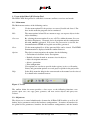
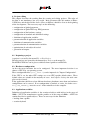
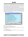
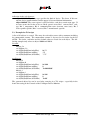
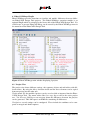
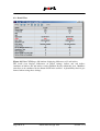
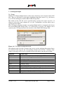
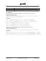
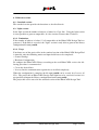
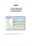
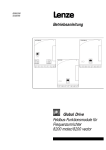
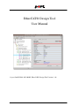
EtherCAT® Design Tool
User Manual
© port GmbH, Halle 2013/02/05; EtherCAT® Design Tool Version 1.1.0
Disclaimer
All rights reserved
The programs, boards and documentations supplied by port GmbH are created with due
diligence, checked carefully and tested on several applications.
Nevertheless, port GmbH can not take over no guarantee and no assume del credere liability that the program, the hardware board and the documentation are error-free respective are suitable to serve the special purpose.
In particular performance characteristics and technical data given in this document may
not be constituted to be guaranteed product features in any legal sense.
For consequential damages, which are emerged on the strength of use the program and
the hardware boards therefore, every legal responsibility or liability is excluded.
port has the right to modify the products described or their documentation at any time
without prior warning, as long as these changes are made for reasons of reliability or
technical improvement.
All rights of this documentation lie with port. The transfer of rights to third parties or
duplication of this document in any form, whole or in part, is subject to written approval
by port. Copies of this document may however be made exclusively for the use of the
user and his engineers. The user is thereby responsible that third parties do not obtain
access to these copies.
The soft- and hardware designations used are mostly registered and are subject to copyright.
CANopen®
is registered trademark, licensed by CiA - CAN in Automation e.V., Germany.
EtherCAT®
is registered trademark and patented technology, licensed by Beckhoff Automation
GmbH, Germany.
We are thankful for hints of possible errors and may ask around for an information.
We will go all the way to verify such hints fastest
Copyright
© 2013 port GmbH
Regensburger Straße 7
D-06132 Halle
Tel. +49 345 - 777 55 0
Fax. +49 345 - 777 55 20
E-Mail [email protected]
Internet http://www.port.de
Table of Contents
1. Introduction .
.
.
.
.
.
.
.
.
.
.
.
.
.
.
.
.
.
.
7
.
.
.
.
.
.
.
.
.
.
.
.
.
.
.
.
.
.
.
.
.
.
.
.
.
.
.
.
.
.
.
.
.
.
.
.
.
.
.
.
.
.
.
.
.
.
.
.
.
.
.
.
.
.
.
.
.
.
.
.
.
.
.
.
.
.
.
.
.
.
.
.
.
.
.
.
.
.
.
.
.
.
.
.
.
.
.
.
.
.
7
7
7
7
8
2. Usage of the EtherCAT® Design Tool . .
.
.
.
.
.
.
.
.
.
.
.
.
9
.
.
.
.
.
.
.
.
.
.
.
.
.
.
.
.
.
.
.
.
.
.
.
.
9
9
2.2.1. Hardware configurations . . . . . . . . . . . . . . .
2.2.2. Object dictionary . . . . . . . . . . . . . . . . . .
10
10
1.1.
1.2.
1.3.
1.4.
1.5.
.
.
.
Product Overview .
Product Delivery .
System requirements
Installation . . .
Support by port .
2.1. Main menu . .
2.2. Object tree . .
.
.
.
.
.
.
.
.
.
.
.
.
.
.
2.3. Action menus . .
.
.
.
.
.
.
.
.
.
.
.
.
.
.
.
.
.
.
10
2.4. Forms
.
.
.
.
.
.
.
.
.
.
.
.
.
.
.
.
.
.
11
.
.
.
.
.
.
.
.
.
.
.
.
.
.
.
.
.
.
.
.
.
.
.
.
.
.
.
.
.
.
.
.
.
.
.
.
.
.
.
.
.
.
.
.
.
.
.
.
.
.
.
.
.
.
.
.
.
.
.
.
.
.
.
.
.
.
.
.
.
.
.
.
.
.
.
.
.
.
12
12
12
12
12
12
2.4.1.
2.4.2.
2.4.3.
2.4.4.
2.4.5.
2.4.6.
. .
.
.
General Settings . . . . .
General EDS/ESI/XDD settings
Advanced configuration . .
Hardware configurations . .
Mask view . . . . . . .
Structure view . . . . .
2.5. Program control
. .
.
.
.
.
.
.
.
.
.
.
.
.
.
.
.
.
.
15
.
.
.
.
.
.
.
.
.
.
.
.
.
.
.
.
.
.
.
17
. .
.
.
.
.
.
.
.
.
.
.
.
.
.
.
.
.
.
17
3.1.1. Project file . . . . .
3.1.2. Generated files . . .
.
.
.
.
.
.
.
.
.
.
.
.
.
.
.
.
.
.
.
.
.
.
.
.
.
.
.
.
.
.
17
17
3. File structure .
.
.
3.1. Project structure
3.2. Profile files .
.
.
.
.
.
.
.
.
.
.
.
.
.
.
.
.
.
.
.
.
17
. .
.
.
.
.
.
.
.
.
.
.
.
.
.
.
.
.
.
.
.
19
4.1. Beginning a project
.
.
.
.
.
.
.
.
.
.
.
.
.
.
.
.
.
.
19
4. Project editing
Version: 1.1.0
EtherCAT® Design Tool
Page 3 of 35
4.2. Hardware configuration .
4.3. Application variables . .
.
.
.
.
.
.
.
.
.
.
.
.
.
.
4.3.1. Parameterization of application variables .
4.3.2. C Implementation . . . . . . . .
4.4. Communication variables
.
.
.
.
.
.
.
.
.
.
.
.
.
.
.
.
.
.
19
19
. . . . . . . . .
. . . . . . . . .
20
20
. .
.
.
.
.
.
.
.
.
.
.
.
.
.
.
22
.
.
.
.
.
.
.
.
.
.
.
.
.
.
.
.
22
4.5. Generation of source code .
.
.
.
.
.
.
.
.
.
.
.
.
.
.
.
22
4.6. %-Variables .
4.4.1. Parameterization . .
.
.
.
.
.
.
.
.
.
.
.
.
.
.
.
.
.
.
.
.
22
4.7. {}-Expressions .
.
.
.
.
.
.
.
.
.
.
.
.
.
.
.
.
.
.
.
23
4.8. Post-Generation command .
.
.
.
.
.
.
.
.
.
.
.
.
.
.
.
23
5. Generation of user-specific object descriptions .
.
.
.
.
.
.
.
.
.
.
25
5.1. Format descriptors . . . . . . . . . . . . . . . . . .
5.2. Example for HTML documentation . . . . . . . . . . . . .
5.3. Example for Tcl scripts . . . . . . . . . . . . . . . . .
25
26
27
6. EtherCAT-Merge PlugIn .
6.1. Project View
6.2. Detail View .
.
29
. . . . . . . . . . . . . . . . . . . .
. . . . . . . . . . . . . . . . . . . .
29
30
7. CSV-Import PlugIn .
7.1. Usage . .
7.2. Examples
.
.
8. Different versions
.
.
.
.
.
.
.
.
.
.
.
.
.
.
.
.
.
.
.
.
.
.
.
.
.
.
.
.
.
.
.
.
.
.
31
.
.
.
.
.
.
.
.
.
.
.
.
.
.
.
.
.
.
.
.
.
.
.
.
.
.
.
.
.
.
.
.
.
.
.
.
.
.
31
32
. .
.
.
.
.
.
.
.
.
.
.
.
.
.
.
.
.
.
.
33
. . . . . . . . . . . . . . . . . .
. . . . . . . . . . . . . . . . . .
33
33
.
.
33
33
.
.
8.1. Standard version .
8.2. Light version . .
8.2.1. Limitations
8.2.2. Usage . .
Page 4 of 35
.
.
.
.
.
.
.
.
.
.
.
.
.
.
.
.
.
.
.
EtherCAT® Design Tool
.
.
.
.
.
.
.
.
.
.
.
.
.
.
.
.
.
.
Version: 1.1.0
Version: 1.1.0
EtherCAT® Design Tool
Page 5 of 35
Page 6 of 35
EtherCAT® Design Tool
Version: 1.1.0
1. Introduction
1.1. Product Overview
The EtherCAT® Design Tool of port is a software tool for the development of EtherCAT® applications (devices). It manages device data bases from which an Object Dictionary, configuration and initialization files in C-code, an Electronic Data Sheet, a XML
description and a HTML-documentation are created automatically. Furthermore the
driver packages can be configured by the EtherCAT® Design Tool and several hardware
configurations can be managed within one project.
With the EtherCAT® Design Tool an instrument is available which frees the developer of
error-prone activities repeating itself. It ensures consistency of implemented functionality, , Electronic Data Sheet (ESI) and device documentation. In the scope of delivery a
data base with the EtherCAT® communication profiles are contained. Profile databases
are optionally available for various device profiles, for example digital I/O devices
according to CiA-401 or drives according to CiA-402.
The created Object Dictionary supports numerous options of the EtherCAT® library from
port. A tree representation of all implemented parameters and data eases the maintenance
of device software. With the EtherCAT® Design Tool the beginning with the EtherCAT® protocol is less difficult and the development of a device is accelerated.
1.2. Product Delivery
The scope of delivery of the EtherCAT® Design Tool:
• User Manual
• software for EtherCAT® Design Tool
• data bases for device profiles (optional)
All components are available for download.
1.3. System requirements
The EtherCAT® Design Tool runs on PC’s with Microsoft Windows™ or Linux.
Operating System:
Processor:
RAM:
Hard-disk Space:
Windows 2000, Windows XP, Vista, Windows 7, Linux
Pentium IV or later
512 MByte
45 MByte
1.4. Installation
The installation is controlled by menus. For this purpose, unpack the zip-file and start
setup.exe on Windows™ resp. setup.sh on Linux. After this installation you will find the
following directory structure.
Version: 1.1.0
EtherCAT® Design Tool
Page 7 of 35
Design Tool
profiles
projects
S1
S4
help
Figure 1, Directory structure of the EtherCAT® Design Tool
The directory projects contains delivered example projects. For each project a separate
directory is recommended. The data bases are in the directory profiles for the communication profiles and the EtherCAT® device profiles. In this directory own profiles can also
be generated. The directory help serves internal purposes.
After an installation on a Windows™ system the EtherCAT® Design Tool can be started
by the icon on the desktop or via the start menu.
1.5. Support by port
The senior engineers at port support the user by a telephone hot-line and by training courses. Additionally the user can have consultations in the whole field of EtherCAT® e.g.
network planning, network configuration, message distribution, selection of devices and
EtherCAT® Profile implementations.
Please ask at our email address
E-mail:
[email protected]
phone:
+49 345 777 55 - 0
Fax:
+49 345 777 55 - 20
The engineers at port react as soon as possible to your message.
Page 8 of 35
EtherCAT® Design Tool
Version: 1.1.0
2. Usage of the EtherCAT® Design Tool
The EtherCAT® Design Tool is controlled via menus, toolbars, treeviews and masks.
2.1. Main menu
The Main menu consists of the following entries:
File
Via the menu option File the projects are created, loaded and closed. Further, in this menu the program can be terminated.
Edit
The menu options below Edit are meant to copy, cut or paste objects in the
object dictionary.
Generate
By selecting the menu option Generate all Files within the menu Generate
the Object Dictionary , electronic device description and the configuration
file ecat_conf.h is generated. If Generate Documentation is selected, the
documentation in HTML and as plain text will be generated.
Show
Via the menu option Show all the generated files can be viewed. The HTML
Documentation is displayed with the standard browser.
Options
The Options menu organizes the options for the following:
• Generation of electronic device descriptions
• Default selection of mask or structure view for objects.
• Object description structures
• object.c generation
• Font configuration
View options are saved user-specific in the registry (or in a .rc file under
Linux) and generation options are saved project-specific in the project file.
Help
In the Help menu the help for the current mask or the manual can be viewed.
It is shown in the standard browser.
Figure 2, Toolbar
The toolbar below the menu provides a fast access to the following functions: new
project, open, save, cut, copy, paste, generate, add new service objects and query new
releases.
2.2. Object tree
The object tree is central administrative element for all EtherCAT® entities as well as all
further device parameters and for the hardware configurations. It consists of branches for
the global device parameters, branches for the hardware configurations, and the branch
Version: 1.1.0
EtherCAT® Design Tool
Page 9 of 35
for the supported EtherCAT® line. The global ESI/EDS resp. XDD parameters are
parameters such as manufacturer name and product designation which are identical for
every EtherCAT® line.
The individual line entries are split into:
• Device Identity Settings
• Object dictionary
2.2.1. Hardware configurations
The EtherCAT® Design Tool can manage several hardware configurations.
A hardware configuration consists of:
• CPU Settings
Choice and configuration of the CPU or the operating system
• Compiler Settings
Choice and configuration of the used compiler
• EEPROM Settings
Configuration of EtherCAT Slave Controllers (ESC)
By setting the hardware configuration, defines in the file ecat_conf.h are set that configure the Driver Package.
2.2.2. Object dictionary
The object dictionary is divided into different branches for the separate segments.
• data types (Indices 0001h − 025F h )
• communication data (Indices 1000h − 1FFF h )
• manufacturer specific data (Indices 2000h − 5FFF h )
• standardized device profile segment data (Indices 6000h − 9FFF h in blocks of 800h )
• reserved area A000h − FFFF h
The division of the area for standardized device profiles into blocks of 800h was carried
out under special regard to the multi device profile. Operations, as doubling identical
segments, can be implemented simply by the representation of every device profile as a
separate segment.
The individual branches of the object dictionary contain the EtherCAT® objects. These
entities are in turn divided into their sub-index elements.
On activation of the individual components in the tree, action menus are displayed in the
right frame. e.g. for the data import or the accordant object forms.
2.3. Action menus
The action menus differ for every branch of the object tree. Menus are available for:
• operations for the hardware settings
• operations referring to one EtherCAT® line
Page 10 of 35
EtherCAT® Design Tool
Version: 1.1.0
•
•
•
•
operations referring to the object dictionary
operations referring to communication parameters
operations referring to manufacturer specific parameters
operations referring to device profile parameters
Hardware configuration can be:
• added,
• copied,
• deleted,
• imported and exported.
For the object dictionary the following actions are available:
• data import from profile files
• data export to profile files
One can execute for the segment with communication parameters:
• data import from files (profile or EDS/XDD)
• data export to profile files
• creating of new objects (indices)
• creating of new communication service objects
The vendor-specific segment has action buttons for:
• data import from files (profile or EDS/XDD)
• data export to profile files
• creating new objects (indices)
For the device profile segment the following actions are possible:
• data import from files (profile or EDS/XDD)
• data export to profile files
• creating new objects (indices)
• creating of a sub segment
For sub segments the following actions are available:
• data import from files (profile or EDS/XDD)
• data export to profile files
• creating new objects (indices)
• configuration of the sub segment
2.4. Forms
Forms and input masks simplify the data input. Additionally to the following documentation there is a online help for each mask available about <F1>.
Version: 1.1.0
EtherCAT® Design Tool
Page 11 of 35
2.4.1. General Settings
The general settings are meant to define global device settings. With these settings the
EtherCAT® library is configured with the help of the file ecat_conf.h.
2.4.2. General EDS/ESI/XDD settings
The global EDS/ESI/XDD form is used for processing all device global entities, that are
device, manufacturer and ordering data.
2.4.3. Advanced configuration
This mask provides access to special user defines in the configuration file ecat_conf.h.
This file is included in all EtherCAT®-files and should be included in every EtherCAT®-related project file. So compiler directives changed here, will affect the whole
project.
Please enter valid C code like e.g.
#define CONFIG_BIG_RAM_VERSION 1
/* undefine printf */
#define PRINTF
Be carefully with these settings.
2.4.4. Hardware configurations
A hardware configuration can be renamed, duplicated, deleted, imported and exported by
its action menu. The active configuration is marked with a pair of asterisks (*) in the
project tree.
The parameters of the sub sections are explained in the context help for each mask.
2.4.5. Mask view
These forms are a wizard for the communication parameters. In this way, the input of the
parameters is facilitated since the bit values coded are converted into text outputs. Contiguous entities are also parameterized transparently for the operator. Please regard that
the mask view is only available for some objects.
2.4.6. Structure view
The structure view is the universal editor with that all entity parameters can be changed.
It is distinguished into a view for the index parameters and one for the sub-index parameters.
Page 12 of 35
EtherCAT® Design Tool
Version: 1.1.0
Name
Index
Description
Number of index (hexadecimal)
Data Type
Object Code
data type according to EtherCAT®
Kind of object according to EtherCAT® specification:
allowed values: Variable, Array, Record, Domain
name of the object in XDD/EDS/ESI file
description of the object for the documentation and for the
parameter description in XDD files
Object name
Description
Table 1, Elements of the structure view for indices
The data type and the object code are fixed for communication objects in the object range
1000h to 1FFF h to be compliant to the specification.
Version: 1.1.0
EtherCAT® Design Tool
Page 13 of 35
Name
Description
Index
Sub-Index
PDO-Mapping
Number of index (hexadecimal)
number of sub-index (decimal)
if selected, the object can be mapped to a
PDO
object name for sub-index
measurement unit of the object
access permissions seen from EtherCAT®
(according to device type)
type of object
size of object in Bytes
defaultvalue of the variable
lower limit for numerical values
upper limit for numerical values
Backup flag of the object
Setting flag of the object
Implementation type of the object: Managed Constant, Managed Variable, Application Variable, Application Array.
Variable name of the object (if applicable)
Object Name
Unit
Access
Data Type
Size
Value
Lower Limit
Upper Limit
Backup
Setting
C Implementation
C Name
Scope
Lib EDS ESI Doc
x
x
x
x
x
x
x
x
x
x
x
x
x
x
x
x
x
x
x
x
x
x
x
x
x
x
x
x
x
x
x
x
x
x
x
x
x
x
x
x
x
x
x
x
Table 2, Elements of the structure view for Sub indices
Within the Object Name entries internal %-variables can be used. They will be replaced
with the their current value at generation. E.g. %s stores the value of the current subindex and an XDD name like "Output %s" will be replaced with "Output 0", "Output 1"
... or "Output 254". With these substitutions it becomes much more easier to copy or
duplicate objects. All %-variables are described in section %-variables in chapter 4.7.
Page 14 of 35
EtherCAT® Design Tool
Version: 1.1.0
Figure 4, structure view of an object
2.5. Program control
The operation of the entire program is done mostly with the mouse. Changed values are
taken over only at leaving of the mask. E.g. continuous actions such as computation of
new sizes during type variation.
Modifications at a mask can be reset before the mask has been left by pressing the button
"Reset". If default values are available for a mask, these values can be loaded by the button "Default".
Version: 1.1.0
EtherCAT® Design Tool
Page 15 of 35
Page 16 of 35
EtherCAT® Design Tool
Version: 1.1.0
3. File structure
3.1. Project structure
3.1.1. Project file
All data of an project are stored in the project file. Nevertheless it is useful to have a
directory for every project, because the generated files will be stored in the project directory.
The directory ’projects’ under the program directory contains some example projects.
3.1.2. Generated files
The generated files are described in table 3.
File
ec_od.c
ec_objects.h
ec_objects.c
ecat_conf.h
ec_init.c
<edsFileName>.eds
<edsFileName>.xml
<projectName>_docu.txt
<projectName>.html
<projectName>_eeprom.bin
generate.err
Description
Implementation of the object dictionary (C code)
generated application variables (C code)
generated application variables (C code)
configuration file for the library (C code)
initialization file for the library (C code)
generated CANopen EDS file
generated XML file (ESI)
documentation as text for implemented objects
documentation in html for implemented objects
EtherCAT EEPROM data in binary file
information file that contains error and warning
messages
Table 3, Generated files
After generation the files, the object dictionary for the EtherCAT® source library and a
documentation are available. If errors occurred, the files have not been generated and the
errors are listed in generate.err
3.2. Profile files
Profile files contain parts of an object dictionary with the objects and their attributes. The
EtherCAT® Design Tool is delivered with a profile, that contains all communication
objects according to the communication profiles. If communication objects are set up
with the EtherCAT® Design Tool, the entries will be loaded automatically from this profile. Additionally to the communication object data base, profile files for other EtherCAT® device profiles are available from port. By means of these profiles standard
Version: 1.1.0
EtherCAT® Design Tool
Page 17 of 35
applications can be implemented in shortest time.
For demonstration purpose some device profile data bases are delivered with the EtherCAT® Design Tool. Objects from such a device profile data base can be imported, but
without a valid license for this data base the output cannot be created. To order a license
for a device profile please contact [email protected] 〈[email protected]〉.
If parts of a project are to be used in later projects, the data can be exported into a separate file.
Page 18 of 35
EtherCAT® Design Tool
Version: 1.1.0
4. Project editing
This chapter describes the working flow for creating and editing projects. The order of
the flow is not mandatory, but very useful. Basic parameter like the number of EtherCAT® lines and the kind of the device (Slave or Master) should be clear at the beginning
of the development. The necessary steps are the following:
• configuration of global parameter
• configuration of global ESI resp. EDS parameter
• configuration of the hardware settings
• configuration of standard and additional settings
• definition of application variables
• parameterization of application variables
• definition of communication variables
• parameterization of communication variables
• optimization of each object if needed
• generation of outputs
4.1. Beginning a project
A project is created by the menu File → New Project.
Existing projects are opened by the button Open Project or the menu File.
Each EtherCAT® line can be preset with data from a profile or an EDS file.
4.2. Hardware configuration
At first the target hardware has to be configured. The most important decision is to
choose a CPU resp. an operating system.
These configuration files (conf_xxxx.h) can be imported via "Import Configuration".
If the CPU is set, the other CPU settings are set to CPU-specific default values. These
default values are suitable in the majority of cases. At Compiler Settings the used compiler can be selected.
If the application shall be used on different hardware plattforms, more than one hardware
configuration can be created. If no configuration is marked as active, the define CONFIG_USE_TARGET_x must be set to 1 in the makefile or in the compiler.
4.3. Application variables
Definition of application variables is the creation of objects with indices in the range of
2000h − 5FFF h for manufacturer specific profiles or in the range of 6000h − 9FFF h for
standardized device profile objects. There are two ways for the definition:
• loading from a profile
• creation by hand
Version: 1.1.0
EtherCAT® Design Tool
Page 19 of 35
The first way is easier. Certain objects can be selected by means of their index from an
profile. Databases for the standardized EtherCAT® device profiles are available from
port. If a database doesn’t exist yet, all entries can be created by hand. It is distinguished
in parameter for the index and for parameter describing the sub-index.
The index parameter defines the structure of the variable. That means their type, kind
(Variable, Array, Record, Domain), the number of sub-indices , the C implementation
type and a variable name (if applicable) and an object name. Furthermore the variable
can be commented. This comment will be a part of the documentation for this object.
The parameters for sub-indices contain an object name for record or array members, size
and type and access permissions. For each a unit can be assigned. If application-specific
data types for records are used, they have to be defined in the data type section of the
object directory in advance of their usage.
Figure 7, import mask for profiles
4.3.1. Parameterization of application variables
The parameterization of application variables is done in the structure view for the subindex elements.
4.3.2. C Implementation
There are different possibilities of the C implementation of an object. These possibilities
are explained in the following table.
Page 20 of 35
EtherCAT® Design Tool
Version: 1.1.0
Type
Description
Managed Constant
The value of the object cannot be changed and it is managed
by the CoE library.
The value of the object can be modified at run-time from
EtherCAT (according to the access right) and from the application using the function putObj().
The memory for this object is allocated by the CoE library.
An variable of the application is used for this object. If the
value of the object is changed via EtherCAT the variable is
updated automatically. The value of the object can be
changed from EtherCAT or from the application using the
function putObj() or directly using the variable name.
If the optimization option "Create Variable" is active, the
variable is defined (created) by the EtherCAT® Design Tool.
Otherwise an existing variable can be reused.
This setting is only valid for ’Array’ objects. The object
object an C array of the application is used. If the values of
the objects are changed via EtherCAT the array elements are
updated automatically. The value of the objects can be
changed from EtherCAT or from the application using the
function putObj() or directly using the variable name.
Sub index 1 of the object corresponds to the array element 0
if the array in C. This kind of implementation can only be
used, if all sub indices (starting at 1) share the same default
values, limits and access rights.
If the optimization option "Create Variable" is active, the
variable is defined (created) by the EtherCAT® Design Tool.
Otherwise an existing variable can be reused.
Managed Variable
Application Variable
Application Array
Table 4, C implementation types
Hints for migrating from CANopen or Powerlink Design Tool:
With the CANopen Design Tool only ’Application Variable’ resp. ’Application Array’
was possible and with the Powerlink Design Tool only ’Managed Constant’ or ’Managed
Variable’. The EtherCAT Design Tool supports now all implementation types.
At the import of existing projects of the other Design Tools the implementation type is set
according to the setting Options→Import Options→Use Application Variables.
Version: 1.1.0
EtherCAT® Design Tool
Page 21 of 35
4.4. Communication variables
As default the implementationtype for communication objects is ’Managed Variable’ or
’Managed Constant’ but it can be changed to ’Application Variable’ as well. For definition of communication variables the same mechanism is possible as described for the
application variables. Additionally the necessary data are loaded from the communication object database. That means, the structure of the created variables is already defined
and all parameter entries are preset. For EtherCAT® conform devices one has to define at
least the objects:
• Device Type (1000h )
• Identity Object (1018h )
and more.
The EtherCAT® standard requires these objects.
There are special menus for the creation of communication parameter. These can be
reached via the button Add new Communication Service in the action menu of the Communication Segment.
For each EtherCAT® service e.g. PDOs these menus are prepared. On this menus the
user has only to make design decisions. No knowledge about the encoding and the contexts between communication objects is necessary.
4.4.1. Parameterization
For parameterization of communication variables the mask view can be used. With these
forms the parameterization of more complex data like PDO parameter and PDO mapping
is very easy.
4.5. Generation of source code
When the button Generate is pressed the object dictionary implementation in C-code the
initialization and configuration files and furthermore an EDS resp. ESI file for each EtherCAT® line (<ProjectName>line<lineNo>.eds and if activated a documentation
(<project name>.html) are generated. These files are always consistent and contain the
date and the time of generation. Another file (generate.err) contains warnings and
errors. It is recommended, to have a look to this file by means of Show after each generation.
4.6. %-Variables
%-variables can be used in object names and variable names of indices and object names
of sub-indices. In the file objects.c, in the EDS files and in the documentation and also in
the object tree they are replaced by their current values.
Page 22 of 35
EtherCAT® Design Tool
Version: 1.1.0
Name
%i
%s
%l
%f
%p
%q
%u
%v
%t
Description
number of the index
number of the sub-index
number of the line
number of the service (SSDO, CSDO,
RPDO, RPDO-Mapping, TPDO-Mapping,
SRDO, SRDO-Mapping) starting at 1
(index - start of segment) starting at 0
(index - start of segment + 1) starting at 1
(index - start of sub segment) starting at 0
(index - start of sub segment + 1) starting at 1
short name of data type
Table 5, %-variables
When using lower case letters for the variables a decimal value is returned. Otherwise a
hexadecimal value without leading "0x". Variables that are undefined in the current context (e.g. %s at an index) return an empty string.
Examples für the usage of these %-variables can be found at the SDO or PDO objects in
the communication profile.
4.7. {}-Expressions
The {}-expressions allow the usage of %-variables and mathematical operators. Inside of
the braces %-variables, constants (decimal/hexadecimal) and the operators + - * and / can
be used.
Examples for valid object names with {}-expressions:
• output {%i - 0x100}
• state {%p + 100} at device %l
4.8. Post-Generation command
At Generation → Post-Generation Settings the post-generation command can be configured. The post-generation command is executed after the generation of the output files.
The command may be a shell-script or a batch file, or you may run e.g. ’make all’ or start
an arbitrary executable file (e.g. the EDS checker or your compiler). The output of the
command is written into the file generate.err.
Version: 1.1.0
EtherCAT® Design Tool
Page 23 of 35
Page 24 of 35
EtherCAT® Design Tool
Version: 1.1.0
5. Generation of user-specific object descriptions
The Design Tool provides format descriptors for the generation of user-specific object
descriptions in ASCII-format for different document types.
The description template is a text in ASCII-Format including format descriptors for
object-specific information and has to be stored in file list.conf in the working directory.
During the generation of all files the description template is applied to each object. The
Design Tool stores the object list in the file userList.txt in the working directory.
5.1. Format descriptors
The Design Tool supports the following format descriptors:
format
descriptor
%a
%D
%d
%e
%F
%g
%I
%i
%L
%l
%M
%m
%n
%p
%O
%R
%S
%s
%T
Version: 1.1.0
description
access type: RO, WO, RW, RWW, RWR, CONST
refuses write on download: 0 - not valid, 1 - valid
data type according to CiA-309-3 (example: u32)
EDS name of the object index
default value in EDS valid: 0 - not valid, 1 - valid
size in bytes in decimal format (example: 12)
object index in hexadecimal format without prefix (example: 1A00)
object index in decimal format (example: 4096)
line number in hexadecimal format without prefix (example: A)
line number in decimal format (example: 12)
limits in EDS valid: 0 - not valid, 1 - valid
lower (minimum) limit
• for numerical objects: in hexadecimal format with prefix "0x"
(example: 0xFFFFFFFF)
• for string objects: <empty string>
name of the object index in C code
PDO mapping allowed: 0 - not valid, 1 - valid
refuses Read on scan: 0 - not valid, 1 - valid
valid after reset: 0 - not valid, 1 - valid
sub-index in hexadecimal format without prefix (example: A)
sub-index in decimal format (example: 12)
description of the object
Take note that the Design Tool can not convert special characters
because it does not know the desired document type.
EtherCAT® Design Tool
Page 25 of 35
format
descriptor
%U
%u
%V
%v
%z
description
upper limit
• for numerical objects: in hexadecimal format with prefix "0x"
(example: 0xFFFFFFFF)
• for string objects: <empty string>
unit (example: 100 ms)
default value
• for numerical objects: in hexadecimal format with prefix "0x"
(example: 0xFFFFFFFF)
• for string objects: without quotation tags
(example: Test string)
default value
• for numerical objects: in decimal format
(example: 1614872592)
• for string objects: without quotation tags
(example: Test string)
enumeration counter of the object in decimal format, counting starts
with 0 (example: 12, i.e. it is the 12th object)
Table 6, format descriptors
5.2. Example for HTML documentation
Each object in the object dictionary is listed with index, sub-index in bold text style and
the object description. The following example only refers to object 1000h and 1001h.
list.conf:
<p>
<b> object %Ih/%S </b>: %T
</p>
userList.txt:
<p>
<b> object 1000h/0 </b>: The device type specifies the kind of device. The lower
16 bit contain the device profile number and the upper 16 bit an additional information.
</p>
<p> <b> object 1001h/0 </b>: The error register is a field of 8 bits, each for a certain error type. If an error occurs the bit has to be set: Bit 0 generic error, Bit 1
current, Bit 2 voltage, Bit 3 temperature, Bit 4 communication error (overrun,
error state), Bit 5 device profile specific, Bit 6 reserved, Bit 7 manufacturer specific
</p>
Page 26 of 35
EtherCAT® Design Tool
Version: 1.1.0
indication in the web-browser:
object 1000h/0: The device type specifies the kind of device. The lower 16 bit contain the device profile number and the upper 16 bit an additional information.
object 1001h/0: The error register is a field of 8 bits, each for a certain error type. If
an error occurs the bit has to be set: Bit 0 generic error, Bit 1 current, Bit 2 voltage, Bit 3 temperature, Bit 4 communication error (overrun, error state), Bit 5
device profile specific, Bit 6 reserved, Bit 7 manufacturer specific
5.3. Example for Tcl scripts
A list of all objects is created. The entry for each object starts with a comment including
the enumeration counter. The enumeration counter is also used as list index for the list
objTab. The index, sub-index and the default value are listed for each object. The following example only refers to object 1000h and 1001h.
list.conf:
#object %z
set objNum %z
set objTab($objNum,indexHex)
set objTab($objNum,subHex)
set objTab($objNum,defValHex)
0x%I
%S
"%V"
userList.txt:
#object 0
set objNum 0
set objTab($objNum,indexHex)
set objTab($objNum,subHex)
set objTab($objNum,defValHex)
#object 1
set objNum 1
set objTab($objNum,indexHex)
set objTab($objNum,subHex)
set objTab($objNum,defValHex)
0x1000
0
"0x00000000"
0x1001
0
"0x00"
The generated object list can be used after sourcing in a Tcl scripts - especially in the
frame for testing in the Console of the CANopen Device Monitor.
Version: 1.1.0
EtherCAT® Design Tool
Page 27 of 35
Page 28 of 35
EtherCAT® Design Tool
Version: 1.1.0
6. EtherCAT-Merge PlugIn
EtherCAT-Merge provides functions to visualize and modify differences between different EtherCAT® Design Tool projects. The EtherCAT-Merge extension module is an
optional PlugIn which is activated by the license file of the EtherCAT® Design Tool. If a
valid license is present, EtherCAT-Merge can be started by the EtherCAT-Merge menu in
the menu bar of the EtherCAT® Design Tool.
Figure 9, EtherCAT-Merge main window displaying 2 projects
6.1. Project View
The project view shows different settings, sub segments, objects and sub indices with different colors. By using the Merge function in the tool bar these elements can be copied
from one project into the other one.
Via the menu File the modified projects can be saved to disk or imported into the EtherCAT® Design Tool. The menu entries like Save resp. Open refer to the active project
tree. Via Generate Diff Report an overview about the differences between the projects
can be generated. This diff report is an XML file containing all differences.
Via Options several settings can be configured. These include the attributes to be compared or merged and further options.
Version: 1.1.0
EtherCAT® Design Tool
Page 29 of 35
6.2. Detail View
Figure 10, EtherCAT-Merge diff window displaying differences of 2 sub indices
The detail view displays differences of global settings, indices and sub indices.
Attributes of indices and sub indices can be modified directly within this view. Modifications have to be confirmed by the button SAVE in the tool bar. A plausibility check is performed when saving these settings.
Page 30 of 35
EtherCAT® Design Tool
Version: 1.1.0
7. CSV-Import PlugIn
7.1. Usage
With the CVS Import PlugIn objects of the object dictionary can be imported from CSV
files. Thus it is possible to export object definitions from other sources (e.g. data bases)
as a CSV file and import it into the EtherCAT® Design Tool.
The format of the CSV file can be specified using an Input Description Specifier. It
allows to select only some columns of a csv file. Additionally, an object offset can be
speficied for the import.
The CSV Import extension module is an optional PlugIn which is activated by the license
file of the EtherCAT® Design Tool. If a valid license is present, CSV Import can be
started by the CSV Import menu in the menu bar of the EtherCAT® Design Tool.
Figure 11, CVS-Import configuration mask
The following table describes all tokens that can be used for the Input Description Specifier and their value range for the corresponding column in the CSV file. Commas, semicolons or tab stops can be used as separator between the tokens, but only one of them.
Element
index
sub
edsname
varname
access
unit
min,max,default
datatype
objectcode
desc
createvar
Version: 1.1.0
Value range
index in the range between 0x2000 and 0x9FFF
sub index in the range between 0 and 254
arbitrary string
valid C variable name
RO, RW, WO, CONST, RWR, RWW or as lower case letters
arbitrary string
numbers using C notation
EtherCAT® datatype as decimal number (see object dictionary)
VARIABLE (default), ARRAY or SUB
arbitrary string only for VARIABLE or ARRAY
flag if the c-variable shall be created (0 or 1)
EtherCAT® Design Tool
Page 31 of 35
Element
pdomapping
Value range
flag if it can be mapped into a PDO (0 or 1)
7.2. Examples
This examples shows a standard configuration of manufacturer specific objects.
Input Description Specifier:
index,sub,varname,edsname,unit,access,min,max,default,datatype, \
objectcode,createvar,pdomapping
CSV File:
0x3000,0,man_eins,EDSName_1,,ro,0,0xff,0xF0,5,VARIABLE,1,0
0x3001,0,man_zwei,Variable_2,,ro,0,0xff,0xF0,5,VARIABLE,1,0
0x3002,0,man_drei,Ohne_Create_Var,,ro,0,0xff,0xF0,5,VARIABLE,0,1
0x4000,,min_array,Lufthupen,,rw,,,,6,ARRAY,0,0
0x4000,1,,Lufthupe_1,,wo,0,0xf1,0x01,6,SUB,1,1
0x4000,2,,Lufthupe_2,,ro,0,0xf2,0x02,6,SUB,1,1
0x4000,3,,Lufthupe_3,,rwr,0,0xf3,0x03,6,SUB,1,1
The next example shows how to ignore some columns from the CSV file.
Input Description Specifier:
;;;;index;;;varname;;;access;default;datatype;objectcode;edsname
CSV File:
whatever;;ign;;0x2001;0;0;test_1;;;ro;0;6;VARIABLE;Number of Inputs
whatever;;ign;;0x2002;0;0;test_2;;;ro;0;6;VARIABLE;Number of Outputs
whatever;;ign;;0x2003;0;0;test_3;;;ro;0;6;VARIABLE;Number of Variables
Page 32 of 35
EtherCAT® Design Tool
Version: 1.1.0
8. Different versions
8.1. Standard version
The standard version provides the functions as described herein.
8.2. Light version
In the light version the number of objects is limited to 15 per line. Using the light version
it is not possible to generate output files, if a line consists of more than 15 objects.
8.2.1. Limitations
If the number of objects is below 15, all output files of the EtherCAT® Design Tool are
generated. If the limit is exceeded, the ’Light’ version is only able to generate the library
configuration file ecat_conf.h.
8.2.2. Usage
If no future use of the project files in the standard version of the EtherCAT® Design Tool
is intended, only the following masks and input fields have to be completed:
• General Settings
• Hardware Configuration
To configure the EtherCAT® Library according to the used EtherCAT® services the following procedure is recommended:
• Create the desired lines
• In every line the communication segment has to be filled completely.
When the configuration is complete the file ecat_conf.h can be created by Generate all
Files. The project file of EtherCAT® Design Tool light has to be saved too, because it is
not possible to import the Library configuration from a ecat_conf.h.
The project file can be reused in the standard version of the EtherCAT® Design Tool.
Version: 1.1.0
EtherCAT® Design Tool
Page 33 of 35
Page 34 of 35
EtherCAT® Design Tool
Version: 1.1.0
Appendix 1 — Abbreviations
CAN
CAL
CiA
COB
COB-ID
DDE
EMCY
EPL
EPSG
ESI
ETG
NMT
PDO
RPDO
SDO
CSDO
SSDO
SYNC
TIME
TPDO
XDD
XML
Controller Area Network
CAN Application Layer (CANopen base)
CAN in Automation international users and manufacturers group e.V.
Communication Object (CAN Message)
Communication Object Identifier
Device Description Entry
Emergency Object
Ethernet POWERLINK
Ethernet POWERLINK Standardization Group
EtherCAT Slave Information
XML device description for EtherCAT slaves
EtherCAT Technology Group
Network Management
Process Data Objects, they are messages in a unconfirmed service.
They are used for the transfer of real-time data to and from the
device.
Receive PDO
Service Data Objects, they are messages in a confirmed service.
They are used for the access to entries of the object dictionary.
Client SDO
Server SDO
Sychronization Object
Time Stamp Object
Transmit PDO
XML Device Description - device description files for POWERLINK
or CANopen
eXtensible Markup Language
Version: 1.1.0
EtherCAT® Design Tool
Page 35 of 35