1
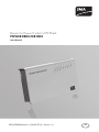
Device for Power Control of PV Plants
POWER REDUCER BOX
User Manual
REDUCERBOX-BA-en-16 | 98-0018716 | Version 1.6
EN
SMA Solar Technology AG
Table of Contents
Table of Contents
1
Information on this Document. . . . . . . . . . . . . . . . . . . . . . . 7
2
2.1
2.2
2.3
2.4
2.5
Safety . . . . . . . . . . . . . . . . . . . . . . . . . . . . . . . . . . . . . . . . . . 9
Intended Use. . . . . . . . . . . . . . . . . . . . . . . . . . . . . . . . . . . . . . . . 9
Supported Products. . . . . . . . . . . . . . . . . . . . . . . . . . . . . . . . . . 10
Qualification of Skilled Persons . . . . . . . . . . . . . . . . . . . . . . . . 11
Safety Precautions. . . . . . . . . . . . . . . . . . . . . . . . . . . . . . . . . . . 11
Operating Instructions. . . . . . . . . . . . . . . . . . . . . . . . . . . . . . . . 12
3
Scope of Delivery . . . . . . . . . . . . . . . . . . . . . . . . . . . . . . . . 13
4
4.1
4.2
4.3
4.4
4.5
Product Description . . . . . . . . . . . . . . . . . . . . . . . . . . . . . . 14
Power Reducer Box. . . . . . . . . . . . . . . . . . . . . . . . . . . . . . . . . . 14
Type Label . . . . . . . . . . . . . . . . . . . . . . . . . . . . . . . . . . . . . . . . 17
LEDs . . . . . . . . . . . . . . . . . . . . . . . . . . . . . . . . . . . . . . . . . . . . . 18
Sunny Portal . . . . . . . . . . . . . . . . . . . . . . . . . . . . . . . . . . . . . . . 18
System Requirements of the Computer . . . . . . . . . . . . . . . . . . . 19
5
5.1
5.2
5.3
5.4
5.5
5.6
The Power Reducer Box User Interface . . . . . . . . . . . . . . 20
User Groups and User Rights . . . . . . . . . . . . . . . . . . . . . . . . . . 20
Overview of the Login Page . . . . . . . . . . . . . . . . . . . . . . . . . . . 21
Overview of the User Interface . . . . . . . . . . . . . . . . . . . . . . . . . 22
Main menu . . . . . . . . . . . . . . . . . . . . . . . . . . . . . . . . . . . . . . . . 22
Context menu . . . . . . . . . . . . . . . . . . . . . . . . . . . . . . . . . . . . . . 23
Status Page . . . . . . . . . . . . . . . . . . . . . . . . . . . . . . . . . . . . . . . . 23
5.7
Events Page. . . . . . . . . . . . . . . . . . . . . . . . . . . . . . . . . . . . . . . . 24
User Manual
REDUCERBOX-BA-en-16
3
Table of Contents
SMA Solar Technology AG
6
6.1
6.2
6.3
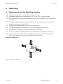
Mounting. . . . . . . . . . . . . . . . . . . . . . . . . . . . . . . . . . . . . . . 25
Requirements for the Mounting Location. . . . . . . . . . . . . . . . . . 25
Mounting the Power Reducer Box on the Wall . . . . . . . . . . . . 26
Mounting the Power Reducer Box on a Top-Hat Rail . . . . . . . . 26
7
7.1
7.2
7.3
Connection . . . . . . . . . . . . . . . . . . . . . . . . . . . . . . . . . . . . . 27
Overview of the Connection Area . . . . . . . . . . . . . . . . . . . . . . 27
Connecting the Power Reducer Box to the Ripple Control
Receiver . . . . . . . . . . . . . . . . . . . . . . . . . . . . . . . . . . . . . . . . . . 28
Lengthening the Connection Cable. . . . . . . . . . . . . . . . . . . . . . 30
8
8.1
Commissioning . . . . . . . . . . . . . . . . . . . . . . . . . . . . . . . . . . 31
Integrating the Power Reducer Box into the Local Network . . . 31
8.1.1
Procedure . . . . . . . . . . . . . . . . . . . . . . . . . . . . . . . . . . . . . . . . . . . . . . . . . . . 31
8.1.2
Connecting the Power Reducer Box to the Computer . . . . . . . . . . . . . . . . . . 31
8.1.3
8.1.4
Setting the Computer to the Standard Network Settings of the
Power Reducer Box. . . . . . . . . . . . . . . . . . . . . . . . . . . . . . . . . . . . . . . . . . . . 32
Setting up a Proxy Exception Rule in Internet Explorer . . . . . . . . . . . . . . . . . 34
8.1.5
Setting the Power Reducer Box to Local Network Settings . . . . . . . . . . . . . . 34
8.1.6
Resetting the Computer to Previous Network Settings. . . . . . . . . . . . . . . . . . 36
8.1.7
Connecting the Power Reducer Box to the Local Network . . . . . . . . . . . . . . 36
8.2
Sunny WebBox Registration in the Power Reducer Box . . . . . . 38
8.2.1
Registering the Sunny WebBox. . . . . . . . . . . . . . . . . . . . . . . . . . . . . . . . . . . 38
8.2.2
Editing/Removing a Sunny WebBox . . . . . . . . . . . . . . . . . . . . . . . . . . . . . . 39
8.3
Configuring Operating Modes . . . . . . . . . . . . . . . . . . . . . . . . . 40
8.3.1
Setting Active Power Limitation . . . . . . . . . . . . . . . . . . . . . . . . . . . . . . . . . . . 42
8.3.2
Setting the Reactive Power Setpoint . . . . . . . . . . . . . . . . . . . . . . . . . . . . . . . 42
8.3.3
Setting the Cos Phi Setpoint . . . . . . . . . . . . . . . . . . . . . . . . . . . . . . . . . . . . . 43
8.3.4
Configuring Combined Operating Modes . . . . . . . . . . . . . . . . . . . . . . . . . . 43
8.3.5
Setting General System Statuses. . . . . . . . . . . . . . . . . . . . . . . . . . . . . . . . . . 44
8.4
Configuring and Activating "Fallback" . . . . . . . . . . . . . . . . . . . 45
4
REDUCERBOX-BA-en-16
User Manual
SMA Solar Technology AG
Table of Contents
9
9.1
9.2
9.3
9.4
9.5
Operation . . . . . . . . . . . . . . . . . . . . . . . . . . . . . . . . . . . . . . 47
Logging In or Out of the Power Reducer Box . . . . . . . . . . . . . . 47
Accessing the Power Reducer Box via Sunny Portal . . . . . . . . . 48
Filtering and Displaying Events . . . . . . . . . . . . . . . . . . . . . . . . . 48
Downloading Events . . . . . . . . . . . . . . . . . . . . . . . . . . . . . . . . . 49
Saving Events to an SD Card . . . . . . . . . . . . . . . . . . . . . . . . . . 49
10
10.1
Settings . . . . . . . . . . . . . . . . . . . . . . . . . . . . . . . . . . . . . . . . 51
Sunny Portal . . . . . . . . . . . . . . . . . . . . . . . . . . . . . . . . . . . . . . . 51
10.1.1
Registering the Power Reducer Box in Sunny Portal . . . . . . . . . . . . . . . . . . . 51
10.1.2
Removing a Power Reducer Box Registered in Sunny Portal from a Plant . . 52
10.1.3
Deactivating Data Transmission to the Sunny Portal . . . . . . . . . . . . . . . . . . . 52
10.2
10.3
10.4
10.5
10.6
Changing your Password . . . . . . . . . . . . . . . . . . . . . . . . . . . . . 53
Resetting your Password . . . . . . . . . . . . . . . . . . . . . . . . . . . . . . 53
Setting the Date and Time. . . . . . . . . . . . . . . . . . . . . . . . . . . . . 54
Setting Protocol Files . . . . . . . . . . . . . . . . . . . . . . . . . . . . . . . . . 54
Firmware Update for the Power Reducer Box. . . . . . . . . . . . . . 55
10.6.1
Configuring an Automatic Firmware Update . . . . . . . . . . . . . . . . . . . . . . . . 55
10.6.2
Performing a Manual Firmware Update . . . . . . . . . . . . . . . . . . . . . . . . . . . . 55
10.6.3
Updating the Firmware via an SD Card . . . . . . . . . . . . . . . . . . . . . . . . . . . . 56
10.7
10.8
Resetting the Power Reducer Box . . . . . . . . . . . . . . . . . . . . . . . 57
Information on the "prb.cfg" File . . . . . . . . . . . . . . . . . . . . . . . . 57
11
11.1
11.2
11.3
11.4
Decommissioning . . . . . . . . . . . . . . . . . . . . . . . . . . . . . . . . 58
Switching the Power Reducer Box Off . . . . . . . . . . . . . . . . . . . 58
Disassembling the Power Reducer Box . . . . . . . . . . . . . . . . . . . 58
Packing the Power Reducer Box for Transportation . . . . . . . . . 58
Disposing of the Power Reducer Box . . . . . . . . . . . . . . . . . . . . 59
User Manual
REDUCERBOX-BA-en-16
5
Table of Contents
SMA Solar Technology AG
12
12.1
12.2
12.3
12.4
Troubleshooting . . . . . . . . . . . . . . . . . . . . . . . . . . . . . . . . . 60
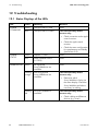
Status Displays of the LEDs . . . . . . . . . . . . . . . . . . . . . . . . . . . . 60
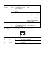
Explanation of the LEDs at the Ethernet Terminal . . . . . . . . . . . 62
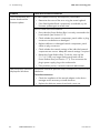
General Troubleshooting . . . . . . . . . . . . . . . . . . . . . . . . . . . . . 63
Error Messages in Connection with Sunny Portal . . . . . . . . . . . 65
12.4.1
Error Messages in the Events Logbook . . . . . . . . . . . . . . . . . . . . . . . . . . . . . 65
12.4.2
Errors During Registration in Sunny Portal. . . . . . . . . . . . . . . . . . . . . . . . . . . 69
13
13.1
13.2
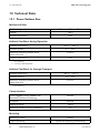
Technical Data . . . . . . . . . . . . . . . . . . . . . . . . . . . . . . . . . . 72
Power Reducer Box. . . . . . . . . . . . . . . . . . . . . . . . . . . . . . . . . . 72
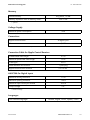
Plug-in Power Supply (CINCON, TRG30R 120) . . . . . . . . . . . 74
14
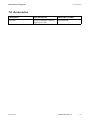
Accessories . . . . . . . . . . . . . . . . . . . . . . . . . . . . . . . . . . . . . 75
15
Contact . . . . . . . . . . . . . . . . . . . . . . . . . . . . . . . . . . . . . . . . 76
6
REDUCERBOX-BA-en-16
User Manual
SMA Solar Technology AG
1
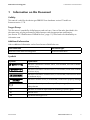
1 Information on this Document
Information on this Document
Validity
This manual is valid for the device type PRB.GR1 from hardware version C2 and from
firmware version 1.7.0.
Target Group
This document is intended for skilled persons and end users. Some of the tasks described in this
document may only be performed by skilled persons with the appropriate qualifications
(see Section 2.3 "Qualification of Skilled Persons", page 11). These tasks are identified by an
information note.
Additional Information
Links to additional information can be found at www.SMA-Solar.com.
Document title
Document type
Reactive Power and Grid Integration
Technical information
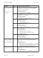
Symbols
Symbol
Explanation
Indicates a hazardous situation which, if not avoided, will result in death
or serious injury
Indicates a hazardous situation which, if not avoided, could result in death
or serious injury
Indicates a hazardous situation which, if not avoided, could result in minor
or moderate injury
Indicates a situation which, if not avoided, could result in property damage
Information that is important for a specific topic or goal, but is not
safety-relevant
☐
Indicates an essential requirement for achieving a specific goal
☑
Desired result
✖
A problem that might occur
User Manual
REDUCERBOX-BA-en-16
7
1 Information on this Document
SMA Solar Technology AG
Typography
Typography
Explanation
"Light"
Example
• Elements on a user interface
• The value can be read off in the
"Energy" field.
• Connections
• Select "Settings".
• Elements to be selected
• Enter the value 10 in the Minutes
field.
• Display messages
• Elements to be entered
>
• Connects several elements
that are to be selected
• Select "Settings > Date".
[Button/Key]
• Button or key to be selected or
pressed
• Select [Next].
Nomenclature
Full designation
Designation in this document
Electronic Solar Switch
ESS
SMA Bluetooth® Wireless Technology
Bluetooth
SMA inverter
Inverter
Sunny WebBox and Sunny WebBox with
Bluetooth® Wireless Technology
Sunny WebBox
Abbreviations
8
Abbreviation Designation
Explanation
AC
Alternating Current
‒
CSV
Comma Separated Values
File format
DC
Direct Current
‒
DHCP
Dynamic Host Configuration Protocol
Protocol for the dynamic assignment of
IP configurations
IP
Internet Protocol
‒
LED
Light-Emitting Diode
‒
PV
Photovoltaics
‒
XML
Extensible Markup Language
‒
REDUCERBOX-BA-en-16
User Manual
SMA Solar Technology AG
2
2 Safety
Safety
2.1 Intended Use
The Power Reducer Box is for PV plants that have to implement network operator setpoints for active
power limitation and reactive power operation under grid management. The Power Reducer Box
complies with the requirements of the German Renewable Energy Sources Act (EEG) for feed-in
management and the requirements of the medium-voltage directive for grid management set out by
the German Association of Energy and Water Industries (BDEW).
The network operator can use the Power Reducer Box to temporarily and remotely limit the feed-in
capacity of the PV plant in the case of a grid overload. The Power Reducer Box translates the control
commands of the network operator and transmits them to the Sunny WebBox. The Sunny WebBox
forwards the control commands to the inverter.
The Power Reducer Box primarily performs the following tasks:
• Active power limitation and reactive power setpoint
• Recording all control commands of the network operator
• Control of up to 2,500 SMA inverters via Sunny WebBoxes
• Data transfer to the Sunny Portal Internet portal for visualisation and optimal notification to the
plant operator
The Power Reducer Box is designed for indoor use only.
The Power Reducer Box is only to be operated using the supplied plug-in power supply and in the
voltage range intended for this.
The Power Reducer Box must only be used with supported products.
For safety reasons, it is not permitted to modify the product or install components that are not explicitly
recommended or distributed by SMA Solar Technology AG for this product. Only use the
Power Reducer Box in accordance with the information provided in the enclosed documentation.
Any other use may result in personal injury or property damage.
The enclosed documentation is is intregal of this product.
• Read and adhere to the documentation.
• Keep the documentation in a convenient place for future reference.
User Manual
REDUCERBOX-BA-en-16
9
2 Safety
SMA Solar Technology AG
2.2 Supported Products
SMA products
Inverters:
You will find an up-to-date list of the inverters supported by the Power Reducer Box in the user
interface of the Power Reducer Box ("Status configuration > Compatibility list") or at
www.SMA-Solar.com. If you have further questions on supported inverters, contact the
SMA Service Line.
Additional products:
• Sunny WebBox from firmware version 1.45*
• Sunny WebBox with Bluetooth firmware version 1.04 or later**
• Sunny Portal
• SMA Update-Portal
* Requirements: the transmission protocol of your plant must be set to SMA-NET and the Sunny WebBoxes must not be
operated in DHCP mode.
** The Sunny WebBoxes must not be operated in DHCP mode.
Products from other manufacturers
Digital signal sources:
• Signal sources with digital relay contacts
Routers and network switches:
• Routers and network switches for Ethernet with 10 Mbit/s or fast Ethernet with 100 Mbit/s
data transfer speed
Plug-in power supply units:
• Input voltage: 100 V … 240 V AC, 50/60 Hz
• Typical power consumption: 4 W
• Maximum power consumption: 12 W
SD cards:
• SD cards with 2 GB memory capacity
10
REDUCERBOX-BA-en-16
User Manual
SMA Solar Technology AG
2 Safety
2.3 Qualification of Skilled Persons
Some of the tasks described in this document may only be performed by skilled persons. These tasks
are identified by an information note. Skilled persons must have the following skills:
• Training in how to deal with the dangers and risks associated with installing and using electrical
devices and plants
• Training in the installation and commissioning of electrical devices and plants
• Knowledge of all applicable standards and directives
• Knowledge of and adherence to this document and all safety precautions
2.4 Safety Precautions
Safety-Relevant Parameters
Safety-relevant operating parameters of the inverters in your plant can be changed using the
Power Reducer Box. These parameters may normally only be changed after consultation with the
power supply company into whose electricity grid you are feeding.
• If you have any doubts, contact your power supply company.
Electrostatic Discharge
By touching electronic components, you may cause damage to or destroy the Power Reducer Box
through electrostatic discharge.
• Earth yourself before touching any components.
Data Security
You can connect the Power Reducer Box to the Internet. When accessing via the Internet, there is the
risk that unauthorised users may access and manipulate the data or devices in your plant.
• Take suitable protective measures (e.g. set up a firewall, close network ports that are not
required, only enable remote access via the VPN tunnel).
• After logging in for the first time, change the default password. Select a number-letter
combination with at least eight characters for your password (see Section 10.2 "Changing your
Password", page 53).
• Keep the password secret and prevent unauthorised persons from accessing it.
User Manual
REDUCERBOX-BA-en-16
11
2 Safety
SMA Solar Technology AG
2.5 Operating Instructions
Inverters Not Supported in the PV Plant
Inverters that are not supported do not implement the parameters via the Power Reducer Box.
The setpoint of the network operator can however be achieved. For this the status configuration of the
Power Reducer Box must be adjusted so that the output of the supported inverters is more strongly
controlled.
• If the network operator requires an active power limitation of 0%, the unsupported inverters must
be disconnected via a suitable switching unit.
• If in doubt, contact your network operator or the SMA Service Line before you commission the
Power Reducer Box.
No DCHP Mode in the Registered Sunny WebBoxes
In the event of changing IP addresses of the Sunny WebBoxes (e.g. in DHCP networks) the
Power Reducer Box does not function correctly. Reset all Sunny WebBoxes to be registered by the
Power Reducer Box to static IP addresses.
Data Traffic via the RPC Interface
Limitation commands from the Power Reducer Box are sent via the Sunny WebBox RPC interface.
Avoid additional data traffic via the Sunny WebBox RPC interface so as not to compromise the speed
of the limitation commands.
12
REDUCERBOX-BA-en-16
User Manual
SMA Solar Technology AG
3
3 Scope of Delivery
Scope of Delivery
Check the scope of delivery for completeness and any externally visible damage.
Contact your specialist dealer if the delivery is incomplete or damaged.
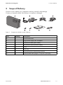
Figure 1:
Components included in scope of delivery
Item
Quantity
Description
A
1
Power Reducer Box
B
1
Plug-in power supply with 4 adapters
C
1
Red Ethernet cable (patch cable)
D
1
Blue Ethernet cable (crossover cable)
E
2
Screw
F
2
Wall plug
G
1
User manual and commissioning checklist
H
1
Pre-terminated cable (length: 2.5 m) with 7-pole plug
User Manual
REDUCERBOX-BA-en-16
13
4 Product Description
4
SMA Solar Technology AG
Product Description
4.1 Power Reducer Box
The Power Reducer Box is for PV plants that have to implement network operator setpoints for active
power limitation and reactive power operation under grid management. The network operator can
use the Power Reducer Box to temporarily and remotely limit the feed-in capacity of the PV plant in
the case of a grid overload. The Power Reducer Box translates the control commands of the network
operator and transmits them to the Sunny WebBox. The Sunny WebBox forwards the control
commands to the inverter.
The Power Reducer Box primarily performs the following tasks:
• Active power limitation and reactive power setpoint
• Recording all control commands of the network operator
• Control of up to 2,500 SMA inverters via Sunny WebBoxes
• Data transfer to the Sunny Portal Internet portal for visualisation and optimal notification to the
plant operator
Four digital states (e.g. a ripple control receiver) can be imported with the Power Reducer Box and
the inverters can be set according to the specifications of the network operator. The four inputs can
be freely configured via the integrated user interface on the Power Reducer Box. If a signal from the
ripple control receiver is present, the Power Reducer Box analyses the signal and relays an instruction
via the Ethernet network to the registered Sunny WebBoxes. The Sunny WebBoxes contacted transfer
the instruction to the connected inverters.
Events are recorded in the internal memory of the Power Reducer Box. It is also possible to save events
onto an SD card or to download events via the user interface.
The Power Reducer Box sends the event data to the Sunny Portal. The Sunny Portal can display the
sent data and inform the user of this by e-mail in the event of applied power limitations.
The Power Reducer Box can automatically update its firmware via the SMA Update-Portal if a new
update is available. For this purpose, the Power Reducer Box must have an Internet connection.
14
REDUCERBOX-BA-en-16
User Manual
SMA Solar Technology AG
4 Product Description
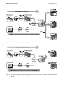
Figure 2:
Principle of implementing grid management with the Power Reducer Box and the Sunny WebBox
Figure 3:
Principle of implementing grid management with the Power Reducer Box and the Sunny WebBox with
Bluetooth
User Manual
REDUCERBOX-BA-en-16
15
4 Product Description
SMA Solar Technology AG
Connecting the Power Reducer Box to the local network
The diagram for the principle of implementing grid management does not replace the exact
terminal assignment for connecting the Power Reducer Box to the local network. The exact
terminal assignment can be found in Section 8.1.7 "Connecting the Power Reducer Box to the
Local Network", page 36.
Operating Mode
• Active power limitation
• Reactive power setpoint with active power output
16
REDUCERBOX-BA-en-16
User Manual
SMA Solar Technology AG
4 Product Description
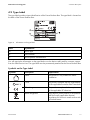
4.2 Type Label
The type label provides unique identification of the Power Reducer Box. The type label is located on
the back of the Power Reducer Box.
Figure 4:
Information on the type label
Item
Explanation
A
Device type
B
Serial number
C
Device-specific characteristics
You will require the information on the type label to use the device safely and for customer support
from the SMA Service Line. The type label must be permanently attached to the Power Reducer Box.
Symbols on the Type Label
Symbol
User Manual
Description
Explanation
Indoor
The product is only suitable for indoor
installation.
C-Tick
The product complies with the requirements
of the applicable Australian EMC standards.
CE marking
The product complies with the requirements
of the applicable EC directives.
WEEE designation
Only dispose of the product in accordance
with the locally applicable disposal
regulations for electronic waste and not with
household waste.
REDUCERBOX-BA-en-16
17
4 Product Description
SMA Solar Technology AG
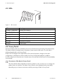
4.3 LEDs
Figure 5:
LED overview
LED
Meaning
POWER COMMAND
Validity of the setpoint
POWER STATUS
Status of the power limitation
WEBBOXCOM
Communication with Sunny WebBox
NETCOM
Activity in the Ethernet network
SD CARD
Status of the SD card
SYSTEM
Operational readiness
POWER
Power supply
4.4 Sunny Portal
The Power Reducer Box can send data to the Sunny Portal Internet portal (www.SunnyPortal.com).
This data includes for example status information, system statuses and events. The sent data is
displayed graphically in the Sunny Portal.
Events such as changes to the requirements of the network operator, changes to the status
configuration or disturbances can be saved in the Sunny Portal plant logbook. In addition,
the Sunny Portal can inform the user of actual events via e-mail (see Sunny Portal for Sunny WebBox
user manual).
Currentness of the data in Sunny Portal
The Power Reducer Box sends data to the Sunny Portal as soon as events occur or settings are
made via the user interface. The data in Sunny Portal can be displayed with a time delay,
depending on your Internet connection and the processing of data in Sunny Portal.
18
REDUCERBOX-BA-en-16
User Manual
SMA Solar Technology AG
4 Product Description
4.5 System Requirements of the Computer
Supported Internet browsers:
• Microsoft Internet Explorer from version 8
• Mozilla Firefox from version 3.6
• Google Chrome from version 23.0
• Apple Safari from version 5.1.7
• Opera from version 12
Recommended screen resolution:
• At least 1,024 pixels x 768 pixels
User Manual
REDUCERBOX-BA-en-16
19
5 The Power Reducer Box User Interface
5
SMA Solar Technology AG
The Power Reducer Box User Interface
5.1 User Groups and User Rights
The Power Reducer Box differentiates between three user groups:
• User
• Installer
• Service
"Service" user group
The "Service" user group is exclusively restricted to SMA service employees.
In order to prevent two users effecting contradictory settings at the same time, only one user can ever
be logged on to the Power Reducer Box at one time.
In addition to the rights of the "User" user group, the "Installer" user group has the following rights:
• Changing the status configuration
• Registering and editing Sunny WebBoxes in the Power Reducer Box
• Resetting the "User" user group password
20
REDUCERBOX-BA-en-16
User Manual
SMA Solar Technology AG
5 The Power Reducer Box User Interface
5.2 Overview of the Login Page
Figure 6:
Login page of the Power Reducer Box on the computer
Item
Description
A
Device status
B
Language selection
C
Login area
D
Serial number and software version
E
Last update to page content
User Manual
REDUCERBOX-BA-en-16
21
5 The Power Reducer Box User Interface
SMA Solar Technology AG
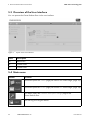
5.3 Overview of the User Interface
You can operate the Power Reducer Box via the user interface.
Figure 7:
Layout of the user interface
Item
Description
A
Main menu
B
Context menu
C
Content area
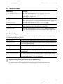
5.4 Main menu
Button
Function
This button opens the "Status" page (see Section 5.6 "Status Page", page 23).
This button opens the "Events" page (see Section 5.7 "Events Page", page 24).
This button opens the "Network and system settings" page of the
Power Reducer Box.
You can log out using this button.
22
REDUCERBOX-BA-en-16
User Manual
SMA Solar Technology AG
5 The Power Reducer Box User Interface
5.5 Context menu
Menu item
Function
Sunny WebBox registration
This menu item opens the "Sunny WebBox registration"
page (see Section 8.2 "Sunny WebBox Registration in the Power
Reducer Box", page 38).
Status configuration
This menu item opens the "Status configuration"
page (see chapter 8.3 "Configuring Operating Modes", page 40).
Password settings
This menu item opens the "Password settings" page.
Sunny Portal settings
This menu item opens the "Sunny Portal settings"
page (see Section 4.4 "Sunny Portal", page 18).
Update settings
This menu item opens the "Update settings" page (see Section
10.6 "Firmware Update for the Power Reducer Box", page 55).
5.6 Status Page
On the "Status" page, an overview of the current status of the PV plant is given in the upper area.
The following information is shown:
Device status
The device status displays the overall status of the Power Reducer Box.
Operating mode
The operating mode displays the setpoint that the Power Reducer Box
is currently implementing.
Setpoint (set)
The setpoint (target) displays the values that have been configured in
the Power Reducer Box for the parameter.
Setpoint (current)
The setpoint (current) displays the values that are currently being
implemented.
Status of the input ports
The status shows the current incoming signal from the ripple control
receiver. K1 to K4 relate to the respective connected relays. If no signal
is incoming, the value "Open" is displayed.
Display of the current status of the Power Reducer Box
The device status is also displayed on the login page of the Power Reducer Box.
User Manual
REDUCERBOX-BA-en-16
23
5 The Power Reducer Box User Interface
SMA Solar Technology AG
In the lower area all Sunny WebBoxes registered in the Power Reducer Box are listed with their
current communication status. A Sunny WebBox can have the following status:
Symbol
Status
Description
OK
The communication between the Power Reducer Box and
Sunny WebBox is functioning is correctly.
Configuration failure There is a communication error between the Power Reducer Box
and the Sunny WebBox. This error is displayed if no
Sunny WebBox is selected.
Error
There is a communication error between the Power Reducer Box
and the Sunny WebBox. There is communication with at least
one connected Sunny WebBox.
Error
There is no configured ripple control signal.
Updating the Device Status
Automatic update of the page content
The page content is automatically updated every 30 seconds.
You can update the device status manually:
1. Select "Status" in the main menu.
2. Select [Refresh].
5.7 Events Page
All events of the Power Reducer Box, such as change to status or communication error, are logged
and displayed on the "Events" page. All events are saved in the internal memory. Once the internal
memory has reached its capacity, the oldest events will be overwritten. In addition you can download
events in CSV format as well as save events to an SD card.
24
REDUCERBOX-BA-en-16
User Manual
SMA Solar Technology AG
6
6 Mounting
Mounting
6.1 Requirements for the Mounting Location
☐ The Power Reducer Box is only suitable for indoor mounting.
☐ The ambient temperature must be between ‒20°C and +60°C during operation.
☐ The Power Reducer Box should be protected from dust, wet conditions, corrosive substances
and vapours.
☐ The cable length of the digital connection between the Power Reducer Box and the ripple
control receiver must not exceed 30 m.
☐ The device should be located near to a 230 V socket-outlet.
☐ The cable feeds require approximately 15 cm of space below the enclosure.
☐ Lay the cables so that they cannot loosen due to their own weight.
☐ Do not cover the Power Reducer Box. This can lead to heat accumulation in the device.
☐ You can mount the Power Reducer Box together with the necessary network technology
(e.g. network switch, router, power supply units) in one enclosure.
Minimum clearances:
Figure 8:
User Manual
Minimum clearances
REDUCERBOX-BA-en-16
25
6 Mounting
SMA Solar Technology AG
6.2 Mounting the Power Reducer Box on the Wall
1. Determine the mounting location.
2. Mark the position of the drill holes on the wall (spacing of drill holes: 75 mm).
3. Drill holes with a diameter of 6 mm at the marked points.
4. Insert wall plugs into the holes.
5. Screw in the screws and leave approximately 6 mm protruding from the wall.
6. Hang the Power Reducer Box on the screws.
6.3 Mounting the Power Reducer Box on a Top-Hat Rail
1. Hook both lower brackets of the Power Reducer Box under the lower edge of the top hat rail.
2. Push the Power Reducer box upwards and snap the top-hat rail into the upper brackets.
26
REDUCERBOX-BA-en-16
User Manual
SMA Solar Technology AG
7
7 Connection
Connection
7.1 Overview of the Connection Area
Figure 9:
Overview of the connection area
Item
Description
A
Connection for the plug-in power supply
B
AUXCOM for connection to the ripple control receiver
C
Ethernet connection
D
SD card slot
All other connections on the Power Reducer Box have no function.
User Manual
REDUCERBOX-BA-en-16
27
7 Connection
SMA Solar Technology AG
7.2 Connecting the Power Reducer Box to the Ripple Control
Receiver
Danger to life due to electric shock from faulty cable connections between the
Power Reducer Box and the ripple control receiver
In the event of faulty cable connections to the Power Reducer Box, mains voltage may be present in
the Power Reducer Box enclosure.
• Do not connect wires from the Power Reducer Box cable to line conductors of the ripple
control receiver.
• The exact wiring is shown in the following circuit diagram.
• When connecting, ensure that no phase bridge has been used in the ripple control receiver.
If applicable, remove the phase bridge.
Damage to the Power Reducer Box or the ripple control receiver due to incorrect
connections
• The Power Reducer Box must only be connected to a ripple control receiver by an electrically
skilled person.
Configuration of the ripple control receiver
The configuration of the ripple control receiver depends on the device and manufacturer.
• Observe the manufacturer's technical documentation.
28
REDUCERBOX-BA-en-16
User Manual
SMA Solar Technology AG
7 Connection
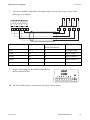
1. Connect the prefabricated cable to the ripple control receiver. The wiring is shown in the
following circuit diagram.
Insulated wire colour* Signal
Power Reducer Box
Description
AUXCOM terminal
grey
+5 V
6
Voltage Supply
white
K1
1
Relay contact 1
brown
K2
2
Relay contact 2
green
K3
4
Relay contact 3
yellow
K4
5
Relay contact 4
* DIN 47100 without colour repetition
2. Plug the 7-pole plug into the AUXCOM terminal on
the Power Reducer Box.
☑ The Power Reducer Box is connected to the ripple control receiver.
User Manual
REDUCERBOX-BA-en-16
29
7 Connection
SMA Solar Technology AG
7.3 Lengthening the Connection Cable
If the length of the prefabricated cable is not sufficient to connect the Power Reducer Box to the ripple
control receiver, a longer cable can be connected to the supplied plug and used.
Additional required mounting material (not included in the scope of delivery):
☐ LiYCY shielded connection cable, with 5 insulated wires, conductor cross-section 0.5 mm2,
max. 30 m long
☐ 11 bootlace ferrules
1. Open the plug and connect the supplied cable.
2. Remove 4 cm of the cable sheath from the cable to be connected.
3. Strip approximately 6 mm of insulation off the wires.
4. Twist the cable shield and plug it into a heat-shrink tubing.
5. Fit the cables with bootlace ferrules.
6. Connect the twisted cable shield to pin 7 on the
plug.
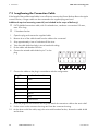
7. Connect the cables to the plug in accordance with the configuration.
Plug/Pin
Insulated wire colour
1
white
2
brown
3
−
4
green
5
yellow
6
grey
7
cable shield
8. Insert the plug into the connector housing and attach the connection cable to the strain relief.
9. Put the cover on the connector housing and close the connector housing.
10. At the other end of the cable, equip the wires with bootlace ferrules, shorten the cable shield
and insulate.
30
REDUCERBOX-BA-en-16
User Manual
SMA Solar Technology AG
8
8 Commissioning
Commissioning
8.1 Integrating the Power Reducer Box into the Local Network
8.1.1 Procedure
Procedure
See
1
Connecting the Power Reducer Box to the Computer
Section 8.1.2
2
Setting the computer to the Standard Network Settings of the Power Reducer Box Section 8.1.3
3
When using a proxy server: Setting up a Proxy Exception Rule in Internet Explorer Section 8.1.4
4
Setting the Power Reducer Box to Local Network Settings
Section 8.1.5
5
Resetting the Computer to Previous Network Settings
Section 8.1.6
6
Connecting the Power Reducer Box to the Local Network
Section 8.1.7
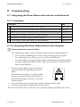
8.1.2 Connecting the Power Reducer Box to the Computer
Recommendation for network cabling
If the supplied patch cable is too short, observe the following patch cable requirements:
• You will need a shielded Ethernet crossover cable of cable type Cat5 or higher.
• For a total length of up to 50 m you can use a cable with AWG26/7.
• For a total length of no more than 100 m, observe the directives for structured cabling in
accordance with EIA/TIA-568, ISO/IEC 11801 and/or EN 50173 (cable for fixed
layout at least AWG24).
1. Connect the Power Reducer Box to the computer
with the blue Ethernet cable (Ethernet crossover
cable).
The terminal on the computer is usually identified
with the same symbol as the network terminal on
the Power Reducer Box. If necessary, refer to the
computer manual.
2. Connect the DC plug of the plug-in power supply to the Power Reducer Box.
3. Connect the plug-in power supply plug to the socket-outlet.
☑ The Power Reducer Box is switched on and is operational after approximately 90 seconds.
User Manual
REDUCERBOX-BA-en-16
31
8 Commissioning
SMA Solar Technology AG
8.1.3 Setting the Computer to the Standard Network Settings of the
Power Reducer Box
Changing network settings
Do not change any of the network setting values if you are not sure of the consequences of the
changes. It is possible to adjust the settings in such a way that your existing network no longer
works at all or only partially. In the worst case, the computer will no longer be able to
communicate with the Power Reducer Box. In order to be able to make changes to the network
settings, you will require the necessary user rights on the computer. If in doubt, contact your
network administrator.
Windows Vista, Windows 7
1. Start the computer.
2. In Windows, select "Start".
3. Enter "ncpa.cpl" in the search field and press the enter key.
☑ The "Network Connections" window opens.
4. Double click on the LAN connection used to connect the Power Reducer Box to the computer.
• If Windows displays several LAN connections, there are probably several network
connections installed on the computer. Ensure that you select the correct network connection
that the computer is using to connect to the Power Reducer Box. If necessary, refer to the
manual of your computer.
• If no LAN connection is displayed, read Section 12.3 "General Troubleshooting", page 63.
☑ The "Local Area Connection Status" window opens.
5. In the "General" tab, select [Properties].
☑ The "Local Area Connection Properties" window opens.
6. Select "Internet Protocol Version 4 (TCP/IPv4)" and click [Properties].
☑ The "Internet Protocol Version 4 (TCP/IPv4) Properties" window opens.
7. Make a note of the existing network settings in the "Internet Protocol Version 4 (TCP/IPv4)
Properties" window. With this, you can reset the computer to the previous network settings after
configuring the Power Reducer Box.
8. Adjust the following static network settings for the computer:
• Select the "Use the following IP address:" field.
• In the "IP address:" field, enter an IP address that is in the same subnet as the IP address for
the Power Reducer Box, e.g. "192.168.0.190". The Power Reducer Box is factory-set to the
IP address "192.168.0.200".
• Enter the subnet mask "255.255.255.0" into the "Subnet mask:" field.
• Delete any entries in the "Default gateway", "Preferred DNS server" and
"Alternate DNS server" fields.
32
REDUCERBOX-BA-en-16
User Manual
SMA Solar Technology AG
8 Commissioning
9. Select [OK].
10. In the "Local Area Connection Properties" window, select [OK].
☑ The computer is set to the network settings of the Power Reducer Box.
Windows XP, Windows 2000
1. Start the computer.
2. In Windows select "Start > Settings > Network Connections".
3. Double click on the LAN connection used to connect the Power Reducer Box to the computer.
• If Windows displays several LAN connections, there are probably several network
connections installed on the computer. Ensure that you select the correct network connection
that the computer is using to connect to the Power Reducer Box. If necessary, refer to the
manual of your computer.
• If no LAN connection is displayed, read Section 12.3 "General Troubleshooting", page 63.
☑ The "Local Area Connection Status" window opens.
4. In the "General" tab, select [Properties].
☑ The "Local Area Connection Properties" window opens.
5. Select "Internet Protocol (TCP/IP)" and click [Properties].
☑ The "Internet Protocol (TCP/IP) Properties" window opens.
6. Make a note of the existing network settings in the "Internet Protocol (TCP/IP) Properties"
window. With this, you can reset the computer to the previous network settings after configuring
the Power Reducer Box.
7. Select the "Use the following IP address:" field.
8. Adjust the following network settings:
• Select the "Use the following IP address:" field.
• In the "IP address:" field, enter an IP address that is in the same subnet as the IP address for
the Power Reducer Box, e.g. "192.168.0.190". The Power Reducer Box is factory-set to the
IP address "192.168.0.200".
• Enter the subnet mask "255.255.255.0" into the "Subnet mask:" field.
9. Delete any entries in the "Default gateway", "Preferred DNS server" and "Alternate DNS server"
fields.
10. Select [OK].
☑ The "Internet Protocol (TCP/IP) Properties" window closes.
11. In the "Local Area Connection Properties" window, select [OK].
12. In the "Local Area Connection Status" window, select [Close].
User Manual
REDUCERBOX-BA-en-16
33
8 Commissioning
SMA Solar Technology AG
8.1.4 Setting up a Proxy Exception Rule in Internet Explorer
If there is an active proxy server in your network, you must set up a proxy exception rule for the
Power Reducer Box in Internet Explorer.
Version of Internet Explorer
The following descriptions apply to Internet Explorer 6. The descriptions are similar and should
be recognisable when using Internet Explorer 5 and version 7 upwards.
1. Start Internet Explorer.
2. In Internet Explorer, select "Tools > Internet Options".
☑ The "Internet Options" window opens.
3. Select the "Connections" tab.
4. Select [Settings].
5. Select [Advanced].
6. In the field "Do not use proxy server for addresses beginning with:" enter "192.168.*".
If necessary, use semicolons to separate entries.
7. Confirm the entries with [OK] and close each further window with [OK].
☑ The proxy exception rule has now been set up.
8. Call up the home page of the Power Reducer Box in the Internet Explorer address bar
(http:\\192.168.0.200).
☑ The Power Reducer Box home page appears.
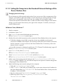
8.1.5 Setting the Power Reducer Box to Local Network Settings
Network administrator
If your local Ethernet is managed by a network administrator, contact him/her before
integrating the Power Reducer Box into your network.
You can allocate static network settings to the Power Reducer Box or obtain the network settings via
a Dynamic Host Configuration Protocol-Server (DHCP server):
• When using the DHCP method, the DHCP server (normally the router, a switch cannot do this)
automatically assigns an IP address to the Power Reducer Box.
• If the network works without a DHCP server, you must assign a fixed IP address to the
Power Reducer Box.
34
REDUCERBOX-BA-en-16
User Manual
SMA Solar Technology AG
8 Commissioning
Assigning Static Network Settings
For delivery, the static network settings of the Power Reducer Box are set to the following values:
IP address:
192.168.0.200
Subnet mask:
255.255.255.0
Http port:
80
Forwarding port
80
SSL port
443
1. Register as "Installer" on the home page of the Power Reducer Box (see Section 9.1 "Logging In
or Out of the Power Reducer Box", page 47).
☑ The "Plant overview" page opens.
2. Select [Network and system settings] in the main menu.
3. Enter the following settings in "Network settings":
• In the "Obtain IP address" field, select the "static" field (default setting).
Allocating IP addresses
Each IP address may only appear once in the local network. The IP address may never
end in 0 or 255.
• In the "IP address" field, enter the IP address under which the Power Reducer Box is to be
accessed.
• In the "Subnet mask" field enter the subnet mask of your network. This mask limits the Ethernet
network to certain IP addresses and separates the network areas from one another.
• In the "Gateway address" field, enter the gateway address of your network. The gateway
address is the IP address of the device that creates the connection to the Internet. Usually,
the address of the router is entered here.
• In the "DNS server address" field, enter the address of the DNS server. The DNS server
(Domain Name System) translates important Internet addresses (e.g.
www.sunnyportal.com) into the respective IP addresses. Type in the DNS server address that
your Internet service provider has given you or, alternatively, enter the IP address of your
router.
4. Select [Save].
☑ The static network settings have been set.
User Manual
REDUCERBOX-BA-en-16
35
8 Commissioning
SMA Solar Technology AG
Obtaining Network Settings Dynamically (DHCP)
Requirements:
☐ There must be an active DHCP server in your local network.
Using DHCP
Before you set the Power Reducer Box to DHCP, check whether your DHCP server can extend
the "lease time" of the IP address allocated. If the DHCP server allocates a new IP address after
the "lease time" has expired, SMA Solar Technology AG advises against using the DCHP
server.
DCHP servers can list all devices to which you have assigned an IP address. You can identify
the Power Reducer Box in the DHCP server by its MAC address. You can find the MAC address
of your Power Reducer Box on the type label.
1. Register as "Installer" on the home page of the Power Reducer Box (see Section 9.1 "Logging
In or Out of the Power Reducer Box", page 47).
☑ The "Plant overview" page opens.
2. Select [Network and system settings] in the main menu.
3. In the "Obtain IP address" field, select the value "dynamic".
4. Select [Save].
☑ The Power Reducer Box obtains its IP address from the local network DHCP server.
8.1.6 Resetting the Computer to Previous Network Settings
• Reset the computer to the previous network settings noted earlier. This allows you to access your
network again.
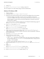
8.1.7 Connecting the Power Reducer Box to the Local Network
Recommendation for network cabling
If the supplied patch cable is too short, observe the following patch cable requirements:
• You will need a shielded patch cable of cable type Cat5 or higher.
• For a total length of up to 50 m you can use a cable with AWG26/7.
• For a total length of no more than 100 m, observe the directives for structured cabling as
described in EIA/TIA-568, ISO/IEC 11801 and/or EN 50173 (cable for fixed layout
at least AWG24).
36
REDUCERBOX-BA-en-16
User Manual
SMA Solar Technology AG
8 Commissioning
The Power Reducer Box has an integrated network terminal. It can use this to connect to every Ethernet
network. The terminal supports both Ethernet and fast Ethernet networks (10/100 Mbit/s). The speed
is switched automatically depending on the connected network switch, router or computer.
COM
ORY
ORT
USB
TEM
ER
REP
MEM
SYS
POW
NET
COM
SMA
COM
Sunny WebBox
Switch / Router
Power Reducer Box
NE
TCOM
SD
CA
RD
SYSTE
M
PO
WER
PO
WER
CO
MM
AN
PO
D
WER
STA
TUS
WEB
BO
XCOM
COM
ORY
ORT
USB
TEM
ER
REP
MEM
SYS
POW
NET
COM
SMA
COM
Sunny WebBox
COM
ORY
ORT
USB
TEM
ER
REP
MEM
SYS
POW
NET
COM
SMA
COM
Sunny WebBox
Figure 10: Power Reducer Box connection to the local network
1. Remove the Power Reducer Box plug-in power supply from the socket-outlet.
2. Remove the blue Ethernet cable.
3. Connect the Power Reducer Box and switch or
router together using the Ethernet terminals. Use the
red Ethernet cable to do this.
4. Connect the plug-in power supply plug to the socket-outlet.
☑ The Power Reducer Box is switched on and is operational after approximately 90 seconds.
User Manual
REDUCERBOX-BA-en-16
37
8 Commissioning
SMA Solar Technology AG
8.2 Sunny WebBox Registration in the Power Reducer Box
8.2.1 Registering the Sunny WebBox
These settings may only be configured by skilled persons
The settings in this section may only be configured by a skilled person
(see Section 2.3 "Qualification of Skilled Persons", page 11).
Only Sunny WebBoxes that are controlled by the Power Reducer Box must be registered in the
Power Reducer Box.
Requirements:
☐ The Sunny WebBoxes must not be operated in DHCP mode.
☐ For Sunny WebBox without Bluetooth: the transmission protocol of your PV plant must be set to
SMA-NET. For this purpose, the type of communication for the Sunny WebBox must be set to
"SMA-COM" (see Sunny WebBox user manual).
1. Select "Sunny WebBox registration" in the context menu.
2. In the upper area, enter the settings for each Sunny WebBox to be registered:
• In the "Name" field, enter the name of the Sunny WebBox. The name can be freely chosen
and serves the display on the "Status" page (maximum 20 characters). If no name is chosen,
the IP address of the Sunny WebBox is entered as default.
1. In the "IP address" field, enter the IP address at which the Sunny WebBox can be reached.
The Sunny WebBox must have a fixed IP address and must not be in DHCP mode.
Tip: if you do not know the IP address of the Sunny WebBox, you can find it in the file "prb.cfg"
(see Section 10.8).
• In the "Port" field, enter the web server port at which the Sunny WebBox can be reached.
The default setting is port 80.
2. Select [Add].
☑ The newly registered Sunny WebBox appears in a list in the lower area.
Valid IP addresses for the Sunny WebBox
It is not checked whether the IP address of the Sunny WebBox is valid. To check that the
Sunny WebBox has been correctly registered, refer to the status display on the "Status" page
(see Section 5.6 "Status Page", page 23).
You can enter additional IP addresses of Sunny WebBoxes in the same way. Please note that a
Power Reducer Box supports a maximum of 50 Sunny WebBoxes.
38
REDUCERBOX-BA-en-16
User Manual
SMA Solar Technology AG
8 Commissioning
8.2.2 Editing/Removing a Sunny WebBox
These settings may only be configured by skilled persons
The settings in this section may only be configured by a skilled person
(see Section 2.3 "Qualification of Skilled Persons", page 11).
Do not remove or edit Sunny WebBoxes while the Power Reducer Point is actively
sending setpoints
If you edit the configuration of Sunny WebBoxes in your plant or remove Sunny WebBoxes
from your plant while the Power Reducer Box is sending an instruction to the them, the signal
from the Power Reducer Box may not be translated correctly.
• Do not remove any Sunny WebBoxes and do not change any Sunny WebBox IP
addresses in the Sunny WebBox registration if an active power limitation (< 100%) or a
reactive power setpoint is currently active.
Editing a Sunny WebBox
1. Select "Sunny WebBox registration" in the context menu.
2. In the list of Sunny WebBoxes, click "Edit"
next to the desired Sunny WebBox.
☑ The Sunny WebBox to be edited is displayed in the upper area.
3. Adjust the Sunny WebBox settings.
4. Select [Save].
☑ The Sunny WebBox is displayed in the list of Sunny WebBoxes with the changed values.
Removing a Sunny WebBox
1. Select "Sunny WebBox registration" in the context menu.
2. In the list of Sunny WebBoxes, click "Remove"
next to the Sunny WebBox to be removed.
☑ The Sunny WebBox is deleted from the list.
User Manual
REDUCERBOX-BA-en-16
39
8 Commissioning
SMA Solar Technology AG
8.3 Configuring Operating Modes
Requirements for configuring operating modes
• Only trained electrically skilled persons may configure the operating modes.
• Only configure the operating modes in consultation with the responsible network
operator.
• Do not configure operating modes if an active power limitation, reactive power setpoint,
cos phi setpoint or a combined setpoint is currently being implemented.
The four digital inputs of the Power Reducer Box (K1, K2, K3, K4) can accept up to 16 different input
statuses. In consultation with the responsible network operator, each input status can be assigned a
different operating mode.
When the Power Reducer Box receives an instruction from the network operator, the inputs of the
Power Reducer Box take on a defined status. If the Power Reducer Box evaluates this input status as
valid, it switches to the operating mode that the input status was assigned with.
The Power Reducer Box evaluates an input status as valid under the following requirements:
• The input status is configured, i.e. the input status is assigned with an operating mode and the
operating mode is configured.
• The input status is activated.
The following operating modes can be configured via the user interface:
Simple operating modes
• "Effective power control"
• "Reactive power setpoint"
• "Cos phi setpoint"
Combined operating modes
• "Active power limitation and reactive power setpoint"
• "Active power limitation and Cos phi setpoint"
Standard factory configuration:
Input
Operating mode "Effective Power Control" Meaning
K1
0%
No active power
K2
30%
Maximum active power of 30%
K3
60%
Maximum active power of 60%
K4
100%
Full active power
40
REDUCERBOX-BA-en-16
User Manual
SMA Solar Technology AG
8 Commissioning
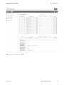
Figure 11: "Status configuration" page
User Manual
REDUCERBOX-BA-en-16
41
8 Commissioning
SMA Solar Technology AG
8.3.1 Setting Active Power Limitation
Active power limitation to 0%
At an active power limitation of 0%, the feed-in power of some string inverters cannot be
decreased to 0 watts. Depending on the inverter type used and the inverter parameters set,
the inverters may continue to feed in a low residual power.
1. Log in as "Installer".
2. Select "Status configuration" in the context menu.
3. Search for the row with the status to be configured in the "Status of the digital input ports" column.
4. Put a tick in the "active" column next to the status to be configured.
☑ The status is active. Upon saving, it will be evaluated by the Power Reducer Box.
5. In the "Operating mode" column, select the "Effective power control" value of the status to be
configured.
6. In the "Active power in %" column of the status to be configured, enter the active power for the
line conductors L1, L2 and L3 in percent.
Different line conductors are only interpreted by inverters with multiple line conductors. In the
case of single-phase inverters, enter the same value for all line conductors.
7. Configure additional statuses in the same way.
8. Adopt the general settings of the system statuses (see Section 8.3.5 "Setting General System
Statuses", page 44).
9. Select [Save].
☑ The active power limitation is set.
8.3.2 Setting the Reactive Power Setpoint
1. Log in as "Installer".
2. Select "Status configuration" in the context menu.
3. Search for the row with the status to be configured in the "Status of the digital input ports" column.
4. Put a tick in the "active" column next to the status to be configured.
☑ The status is active and will be evaluated by the Power Reducer Box upon saving.
5. In the "Operating mode" column, select the "Reactive setpoint value" of the status to be
configured.
6. In the "Reactive power in %" column of the status to be configured, enter the reactive power for
the line conductors L1, L2 and L3 in percent.
Different line conductors are only interpreted by inverters with multiple line conductors. In the
case of single-phase inverters, enter the same value for all line conductors.
7. Configure additional statuses in the same way.
42
REDUCERBOX-BA-en-16
User Manual
SMA Solar Technology AG
8 Commissioning
8. Adopt the general settings of the system statuses (see Section 8.3.5 "Setting General System
Statuses", page 44).
9. Select [Save].
☑ The reactive power setpoint is set.
8.3.3 Setting the Cos Phi Setpoint
1. Log in as "Installer".
2. Select "Status configuration" in the context menu.
3. Search for the row with the status to be configured in the "Status of the digital input ports" column.
4. Put a tick in the "active" column next to the status to be configured.
☑ The status is active and will be evaluated by the Power Reducer Box upon saving.
5. In the "Operating mode" column, select the "Cos phi setpoint" of the status to be configured.
6. In the "cos phi" column of the status to be configured, enter the cos phi values for the line
conductors L1, L2 and L3.
The cos phi value can be between 0.10 and 1.00. Different line conductors are only interpreted
by inverters with multiple line conductors (see inverter manual). In the case of single-phase
inverters, enter the same value for all line conductors.
7. In the "Excitation" column, select whether the cos phi value is overexcited or underexcited.
8. Configure additional statuses in the same way.
9. Adopt the general settings of the system statuses (see Section 8.3.5 "Setting General System
Statuses", page 44).
10. Select [Save].
☑ The cos phi setpoint is set.
8.3.4 Configuring Combined Operating Modes
Configuring combined operating modes
Note that for the combined operating modes, the respective settings must be defined in the
same way as the simple operating modes (see Section 8.3.1to 8.3.3). If you have any doubts,
contact SMA Solar Technology AG.
You can configure the following combined operating modes:
• "Active power limitation and reactive power setpoint"
• "Active power limitation and Cos phi setpoint"
User Manual
REDUCERBOX-BA-en-16
43
8 Commissioning
SMA Solar Technology AG
8.3.5 Setting General System Statuses
1. Log in as "Installer".
2. Select "Status configuration" in the context menu.
3. In the "Failure tolerance time" field, enter the desired failure tolerance time from when an invalid
input signal is recognised as an error. In practice, an invalid input status may be present for a
short time during a status change, e.g. if two relays activate simultaneously for 1 s. The failure
tolerance time should be set to long enough that no error message is generated during this
transition of statuses.
4. In the "Debounce time" field, enter the desired debouncing delay. The value states how long a
signal must be present at a minimum of one input port in order for it to be recognised as such
and subsequently processed by the system. This setting prevents short impulses that are caused
by mechanical contact bounces being falsely recognised as a signal during the status transition.
5. In the "Time interval in case of changed setting" field, enter the time interval in seconds during
which the control command should be sent to the registered Sunny WebBoxes once the setpoint
of the ripple control receiver has changed. Once the setpoint has been reached,
the Power Reducer Box switches to the status "Time interval in case of constant setting".
Example: if 60 seconds is entered, the Power Reducer Box would transmit a control command
to the registered Sunny WebBoxes every 60 seconds with the changed setpoint value.
6. In the "Time interval in case of constant setting" field, select the factor by which the value of the
"Time interval in case of changed setting" should be multiplied. The "Time interval in case of
constant setting" specifies the cycle in which the control command shall be sent to the
Sunny WebBoxes if the setpoint of the ripple control receiver is reached.
7. In the "Maximum change in case of power increase" field, enter the maximum percentage
change per minute after lifting an active power limitation (requirement for reconnecting plants
to the 20 kV electricity grid: max. 10% of the connected active power per minute.)* .
8. In the "Maximum change in case of power decrease" field, enter the maximum percentage
change per minute after a request for an active power limitation.
9. In the "Reference parameter" field, enter the reference parameter for the inverters. The reference
parameter specifies to which value the active power limitation will refer. Ensure that your
connected inverters support the set reference parameter (see "Compatibility list").
10. Select [Save].
☑ The configurations are saved.
* Technical directive "Generating plants connected to the medium-voltage network", BDEW (German Association of Energy and
Water Industries), June 2008
44
REDUCERBOX-BA-en-16
User Manual
SMA Solar Technology AG
8 Commissioning
8.4 Configuring and Activating "Fallback"
"Fallback" is an operating state into which the Power Reducer Box can enter if it evaluates an input
status as invalid.
The Power Reducer Box evaluates an input status as invalid under the following requirements:
• The input status is not configured.
• The input status is not activated.
• The connection between the Power Reducer Box and the ripple control receiver is interrupted
and in addition, the upper constellation of input statues (K1 = 0, K2 = 0, K3 = 0, K4 = 0) on
the "Status configuration“ page is not configured and activated.
The "fallback" prevents the Power Reducer Box from continuing to transmit instructions to the
Sunny WebBoxes in the event of an invalid input status that may no longer be up to date:
If the "fallback" is not activated and not configured, the Power Reducer Box retains the operating
mode of the last valid input status in the event of an invalid input status (e.g. "Effective power control",
"Reactive power setpoint" or "Cos phi setpoint"). If an invalid status is present during an active power
limitation for example, the Power Reducer Box will continue to work in the "Effective power control"
operating mode until a valid input status is again present. If the invalid input status remains unnoticed
over a long period of time, this can lead to yield losses.
If the "fallback" is activated and configured, the Power Reducer Box retains the operating mode of the
last valid input status in the event of an invalid input status for a limited period of time only. How long
the Power Reducer Box retains the operating mode of the last valid input status depends on the time
period that was set for the "fallback". A soon as the set time period expires, the Power Reducer Box
switches to the operating mode that was assigned in the "fallback". In this way, yield losses can be
avoided.
As soon as a valid input status is present, the "fallback" is reset and the Power Reducer Box again sets
the latest requirements of the distribution grid operator.
Time Measurement for "Fallback"
The time measurement begins as soon as an invalid input status is present.
Adjusting settings for the "fallback" during a running time measurement has the following effects on
the "fallback":
Setting
Effect on the fallback
• Changing the time interval for the
"fallback"
The time measurement begins at 0. The newly set
time interval is valid.
• Changing the operating mode (effective
power control, reactive power setpoint,
cos phi setpoint) for the "fallback"
The time measurement continues without
interruption. The newly set operating mode is
valid.
If the Power Reducer Box is reset during the running time measurement or the Power Reducer Box is
switched off (see Section 11.1), the time measurement resumes as soon as the Power Reducer Box is
operational again.
User Manual
REDUCERBOX-BA-en-16
45
8 Commissioning
SMA Solar Technology AG
Configuring and Activating "Fallback"
Configure and activate "fallback" in consultation with the network operator
• Only configure and activate the "fallback" in consultation with the responsible network
operator.
1. Log in to the Power Reducer Box as "Installer".
2. Select "Status configuration" in the context menu.
3. In the "Time" field in the "fallback" area, enter the time interval after which the Power Reducer Box
should switch to "fallback" in the event of an invalid input status. Enter a time interval of between
1 hour and 99 hours.
4. Select the "Active" checkbox.
Upper constellation of the status configuration with "fallback" activated
If the connection between the Power Reducer Box and the ripple control receiver is
interrupted, the following input status is present: K1 = 0, K2 = 0, K3 = 0, K4 = 0
This corresponds to the upper constellation of the input statuses on the
"Status configuration" page. If you have activated "fallback" you should not activate the
upper constellation of the input statuses there. The Power Reducer Box will only evaluate
an interrupted connection to the ripple control receiver as invalid and switch to
"feedback" when the upper constellation of the input statuses is not activated.
5. In the "Operating mode" drop-down list select the desired operating mode for the "fallback".
6. Configure the desired operating mode (see chapter 8.3 "Configuring Operating
Modes", page 40).
7. Select [Save].
46
REDUCERBOX-BA-en-16
User Manual
SMA Solar Technology AG
9
9 Operation
Operation
9.1 Logging In or Out of the Power Reducer Box
Logging in to the Power Reducer Box
Factory settings
User group:
User
Installer
Password:
0000
1111
1. In the browser, enter the IP address of your Power Reducer Box. Tip: if you do not know the IP
address of the Power Reducer Box, you can find it in the file "prb.cfg" (see Section 10.8).
☑ The Power Reducer Box login page appears. If the login page does not open, check the
electrical connection (page 27) and the network configuration (page 34).
2. Select the desired language in the "Language" field.
3. Select the user group in the "User group" field.
4. Enter the password in the "Password" field.
5. Select [Login].
☑ The Power Reducer Box home page appears.
Safety
Once you have logged in for the first time, change your password to protect against
unauthorised access (see Section 10.2).
Logging out of the Power Reducer Box
Logging direclty out of the user interface of the Power Reducer Box will protect your plant against
unauthorised access. If you only close the Internet browser, you will only be logged out of the
Power Reducer Box automatically after 5 minutes.
• Select "Log out" in the main menu.
User Manual
REDUCERBOX-BA-en-16
47
9 Operation
SMA Solar Technology AG
9.2 Accessing the Power Reducer Box via Sunny Portal
If the Power Reducer Box is integrated into a local area network with a router, you can also access
the user interface of the Power Reducer Box via the Sunny Portal.
Ensuring data security in Ethernet networks
When accessing via the Internet, there is the risk that unauthorised users may access and
manipulate the data or devices in your plant.
• Take suitable protective measures (e.g. set up a firewall, close network ports that are not
required, only enable remote access via the VPN tunnel). If in doubt, contact your
network administrator.
Requirements:
☐ The Power Reducer Box must be registered in Sunny Portal (see Section 10.1.1).
☐ Corresponding port forwarding must be set up in the router (see router manual).
The Power Reducer Box must be factory-set to the HTTP port 80 and the forwarding port 80.
• In the Sunny Portal, select the Power Reducer Box on the "Configuration > Device overview"
page.
☑ The Power Reducer Box login page appears.
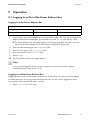
9.3 Filtering and Displaying Events
1. Select "Events" in the main menu.
☑ The events of the current day are displayed.
2. If necessary, filter the events. For this purpose, a tick must be placed in the relevant field.
Multiple selection is possible. The following filter settings are possible:
• Status change
• Information
• Warning
• Error
• Error
3. Select time period.
4. Select [Refresh].
☑ The events in the desired time period are displayed.
48
REDUCERBOX-BA-en-16
User Manual
SMA Solar Technology AG
9 Operation
9.4 Downloading Events
You can download events as a text file in CSV format via the user interface. Only events that are
currently displayed or have been filtered are downloaded. The CSV file uses UTF-8 character
encoding.
1. Select "Events" in the main menu.
2. Select [Download].
3. Select the save location and confirm.
☑ The events are downloaded.
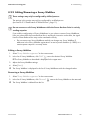
9.5 Saving Events to an SD Card
All events are automatically saved in the internal memory of the Power Reducer Box. You can also
save the events to an SD card. The saving process will begin as soon as you insert the SD card into
the SD card slot. The event of a certain day can only be saved to an SD card on the following day.
If the SD card has reached its capacity, saving is stopped. Old data files are not overwritten on the
SD card. If the "SD-CARD" LED on the Power Reducer Box is red, the SD card is full or write-protected.
Compatibility of the SD cards
In order to ensure the SD card functions properly, use SD cards available from
SMA Solar Technology AG. Compatibility with all SD cards available on the market cannot be
guaranteed. SD cards with a capacity of more than 2 GB and SDHC cards are not supported.
Formatting the SD card
Only use SD cards that have been formatted with the FAT16 file system.
All events are saved onto the SD card daily to the directory /Year/Month/
PREFIX_Year_Month_Day.csv. Example of a daily report from 1st July 2009 with the standard prefix:
/2009/07/PRB_09_07_01.csv All CSV files use UTF-8 character encoding.
Loss of data due to premature removal of the SD card
If the SD card is removed before the writing process has finished the Power Reducer Box restarts.
As a result, data on the SD card can be lost.
• Do not remove the SD card if the "SD CARD" LED is flashing orange or green.
User Manual
REDUCERBOX-BA-en-16
49
9 Operation
SMA Solar Technology AG
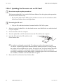
• Insert the SD card into the SD card slot on the
Power Reducer Box.
☑ The events are saved in the internal memory and additionally to the SD card.
You can carry out further settings on the protocol file in the system settings of the Power Reducer Box
(see Section 10.5 "Setting Protocol Files", page 54).
50
REDUCERBOX-BA-en-16
User Manual
SMA Solar Technology AG
10 Settings
10 Settings
10.1 Sunny Portal
10.1.1 Registering the Power Reducer Box in Sunny Portal
Requirements:
☐ Internet access must be available.
☐ All Sunny WebBoxes in your plant must be registered in the Power Reducer Box
(see Section 8.2).
☐ At least one Sunny WebBox in your plant must be registered in Sunny Portal
(see the Sunny WebBox manual).
1. Log in to the Power Reducer Box as "Installer".
2. Select "Sunny Portal settings" in the context menu.
3. In the "Settings" area, select "Yes" in the "Use Sunny Portal" field.
4. If you want to encrypt communication between the Power Reducer Box and the Sunny Portal
using SSL, select "Yes" in the "Use SSL" field. Tip: If necessary, you can change the factory-set
SSL port 443. To do this, select [Network and system settings] and enter the desired SSL port
under "Network settings".
5. Using the "Communication monitoring" drop-down list, set how often the Power Reducer Box
should report to the Sunny Portal. If the Power Reducer Box does not report to the Sunny Portal
within the set time period, the Sunny Portal can inform you via e-mail.
Frequency of communication monitoring when using a GSM modem
If your Internet connection is via a GSM modem, set a low frequency for the
communication monitoring. Depending on your GSM tariff, you will therefore avoid
increased costs.
6. If there is an active proxy server in your network, adopt the settings for the proxy server:
• Select [Network and system settings] and "Network settings" in the main menu.
• Select "Yes" in the "Use proxy server" field.
• Enter the address of the proxy server into the "Proxy server address" field.
• In the "Port" field, enter the network port at which the proxy server can be contacted.
• If you have to authenticate for your proxy server, select "Yes" in the "Use authentication" field
and enter the username and password for the proxy server in the "User ID" and "Password"
fields.
• Select [Save].
User Manual
REDUCERBOX-BA-en-16
51
10 Settings
SMA Solar Technology AG
7. In the "Registered plants request" area, enter the login details with which your plant is registered
in Sunny Portal.
• In the "Operator e-mail" field, enter the e-mail address.
• In the "Password" field, enter the password with which you log in to Sunny Portal.
• Select [Request].
☑ In the "Plant selection" area, a list of the plants registered in Sunny Portal is displayed in the
"Plant name" drop-down list.
8. Select the desired plant from the "Plant name" drop-down list.
9. Select [Select].
☑ In the "Settings" area the name of the plant appears in the "Plant name" field and the plant
identifier in the "Plant identifier" field. The Power Reducer Box is registered in Sunny Portal.
10.1.2 Removing a Power Reducer Box Registered in Sunny Portal
from a Plant
In the following cases, a Power Reducer Box registered in Sunny Portal must be removed from a plant:
• You selected the wrong plant during registration of the Power Reducer Box (see Section 10.1.1).
• You have reset the Power Reducer Box (see Section 10.7).
• If you no longer use the Power Reducer Box.
Procedure:
• Remove the Power Reducer Box in Sunny Portal (see Sunny Portal user manual,
Section "Deleting a Device").
☑ You can re-register the Power Reducer Box in Sunny Portal (see Section 10.1.1).
10.1.3 Deactivating Data Transmission to the Sunny Portal
1. Log in to the Power Reducer Box as "Installer".
2. Select "Sunny Portal settings" in the context menu.
3. In the "Sunny Portal settings" area deselect "Yes" in the "Use Sunny Portal" field.
☑ The Power Reducer Box does not transmit data to the Sunny Portal.
52
REDUCERBOX-BA-en-16
User Manual
SMA Solar Technology AG
10 Settings
10.2 Changing your Password
Password security
In order to increase security, note the following points when selecting a password:
• Minimum eight characters
• Mix upper-case and lower-case letters
• Use numbers and special characters
1. Select "Password settings" in the context menu.
2. In the "Change Passwords" area, adjust the corresponding settings:
• Enter the old password in the "Old password" field.
• Enter the new password in the "New password" field.
• Re-enter the new password in the "Repeat password" field.
3. Select [Save].
☑ The settings will be active at the next login.
10.3 Resetting your Password
Resetting passwords of other user groups
The password of the "User" user group can also be reset in the "Installer" user group.
1. Select "Password settings" in the context menu.
2. In the "Reset password" area, select the user group that is to be reset.
3. Select [Reset].
☑ The password is reset to the factory-set password and will be active at the next login.
User Manual
REDUCERBOX-BA-en-16
53
10 Settings
SMA Solar Technology AG
10.4 Setting the Date and Time
Automatic time synchronisation
If an automatic time synchronisation with Sunny Portal should take place (logging in to
Sunny Portal is not necessary for this), place a checkmark next to "Time synchronisation". Manually
entering the date and time is then no longer necessary. Note that the Power Reducer Box must
have an Internet connection.
1. Select [Network and system settings] in the main menu.
2. Select the current date in the Day-Month-Year format in the "New date: Day, Month, Year" field.
3. In the "New time (hh:mm) 24h time format" field, enter the current time in the hour: minutes
format.
4. In the "Timezone" field, select the time zone in which the PV plant is located.
5. Select [Save].
☑ The date and time are set.
10.5 Setting Protocol Files
1. Select [Network and system settings] in the main menu.
2. In the "Prefix for protocol files" field, select the prefix with which the file name of the protocol file
should begin.
3. In the "Language in protocol files" field, select the language to be used for writing events to the
SD card.
4. Select [Save].
☑ Events are written to the SD card in the selected language.
54
REDUCERBOX-BA-en-16
User Manual
SMA Solar Technology AG
10 Settings
10.6 Firmware Update for the Power Reducer Box
10.6.1 Configuring an Automatic Firmware Update
You can set the Power Reducer Box to automatically update its firmware if a new update is available
in the SMA Update-Portal.
Requirements:
☐ The Power Reducer Box must be integrated into the local network (see Section 8.1) and must
be connected to the Internet via a router. In addition, there must be a permanent Internet
connection set up in the router (see the router manual).
1. Select "Update settings > Automatic update" in the context menu.
2. Select "Yes" in the "Activate update" field.
3. Configure the time settings for the automatic update:
• In the "Install update at (hh:mm): 24-hour format" field, enter the time at which the update
should be installed in the Power Reducer Box.
• In the "Check for update at (hh:mm): 24-hour format" field, enter the time at which the
Power Reducer Box should search for available updates in the SMA Update-Portal.
• In the "Download update at (hh:mm): 24-hour format" field, enter the time at which the
Power Reducer Box should download the update.
4. Select [Save].
10.6.2 Performing a Manual Firmware Update
1. Select "Update settings > Manual update" in the context menu.
2. Select [Execute] in the "Check for new updates" field.
3. Select [Execute] in the "Download update" field.
☑ The firmware update is downloaded and the progress of the download is displayed in the
status bar. If the firmware update does not download, the SMA Update-Portal may be
temporarily unavailable or there may be a problem in the local network.
• Determine the cause of the error by troubleshooting (see Section 12.3 "General
Troubleshooting", page 63).
4. Select [Execute] in the "Install update" field.
☑ The Power Reducer Box installs the firmware update. The update procedure takes
approximately 15 minutes. A red LED light chaser indicates that the update procedure is
running. During the update, the Power Reducer Box restarts. During the restart,
the Power Reducer Box does not implement settings. The configured settings remain the
same. After the update has successfully completed, the Power Reducer Box is available
again via the user interface and the "POWER" and "SYSTEM" LEDs are red.
User Manual
REDUCERBOX-BA-en-16
55
10 Settings
SMA Solar Technology AG
10.6.3 Updating the Firmware via an SD Card
Do not interrupt the update procedure!
The firmware update fails if you switch off the Power Reducer Box during the update procedure
or remove the SD card too early.
• Do not switch off the Power Reducer Box and do not remove the SD card whilst the LEDs
of the Power Reducer show a red light chaser.
Formatting the SD card
• Only use SD cards that have been formatted with the FAT16 file system.
1. Select the required update file in the downloads area at www.SMA-Solar.com and download
it to your computer.
2. Connect the SD card to the computer.
3. Save the update file to the SD card and remove the SD card from the computer.
4. Insert the SD card into the SD card slot on the
Power Reducer Box.
☑ The update is performed automatically. The update procedure takes approximately
15 minutes. A red LED light chaser indicates that the update procedure is running. During
the update, the Power Reducer Box restarts. During the restart, the Power Reducer Box does
not implement settings. The configured settings remain the same. After the update has
successfully completed, the Power Reducer Box is available again via the user interface and
the "POWER", "SYSTEM" and "SD CARD" LEDs are green.
5. Remove the SD card from the Power Reducer Box.
56
REDUCERBOX-BA-en-16
User Manual
SMA Solar Technology AG
10 Settings
10.7 Resetting the Power Reducer Box
The reset button is situated in a small hole on the rear side of the Power Reducer Box. Depending on
how long you press the reset button, the Power Reducer Box performs the actions listed in the
following table:
Duration
Action
Up to 1 second
Reset network settings
1 … 5 seconds
Reset network settings and passwords
5 … 15 seconds
Reset all Power Reducer Box settings to the default settings
(= factory settings on delivery).
If you would like to restart the Power Reducer Box without resetting passwords and settings, you must
switch off the Power Reducer Box (see Section 11.1) and then reconnect the plug-in power supply of
the Power Reducer Box to the socket-outlet.
Requirements:
☐ You must be a trained electrically skilled person.
☐ The Power Reducer Box must be supplied with voltage.
• Using a sharp object, push the rest button in the
hole.
☑ The Power Reducer Box is reset.
10.8 Information on the "prb.cfg" File
The "prb.cfg" file is a configuration file that is written onto the SD card after the SD card has been
inserted into the SD card slot on the Power Reducer Box. The file contains the network settings for the
Power Reducer Box as well as the device names and IP addresses of the Sunny WebBoxes registered
in the Power Reducer Box.
User Manual
REDUCERBOX-BA-en-16
57
11 Decommissioning
SMA Solar Technology AG
11 Decommissioning
11.1 Switching the Power Reducer Box Off
Data on the SD card may be lost
If you switch the Power Reducer Box off whilst data is being saved to the SD card, data from the
SD card may be lost.
• Do not switch the Power Reducer Box off if the "SD CARD" LED is flashing orange or green
(see Section 4.3).
• Connect the plug-in power supply to the socket-outlet.
☑ The Power Reducer Box is switched off.
11.2 Disassembling the Power Reducer Box
1. Switch off the Power Reducer Box (see Section 11.1).
2. Remove the DC plug of the plug-in power supply from the Power Reducer Box.
3. Remove the SD card from the SD card slot on the Power Reducer Box.
4. Remove cabling to the ripple control receiver.
5. Remove the Ethernet cable from the Power Reduce Box.
6. Disassemble the enclosure:
Top-Hat Rail Mounting
Remove the enclosure of the Power Reducer Box from the top-hat rail. To do so, lightly press the
Power Reducer Box upwards, tilting the top edge forwards.
Wall Mounting
Remove the enclosure of the Power Reducer Box from the wall. To do so, press the
Power Reducer Box upwards and pull it forwards.
7. If you no longer want to use the Power Reducer Box and it is registered in Sunny Portal, remove
the Power Reducer Box in Sunny Portal (see Section 10.1.2).
☑ The Power Reducer Box is disassembled.
11.3 Packing the Power Reducer Box for Transportation
When returning the device to us, be sure to use packaging that adequately protects the device from
damage during transport (if possible, the original packing).
58
REDUCERBOX-BA-en-16
User Manual
SMA Solar Technology AG
11 Decommissioning
11.4 Disposing of the Power Reducer Box
Dispose of the Power Reducer Box at the end of its service life in accordance with the disposal
regulations for electronic waste that apply at the installation site at that time.
User Manual
REDUCERBOX-BA-en-16
59
12 Troubleshooting
SMA Solar Technology AG
12 Troubleshooting
12.1 Status Displays of the LEDs
LED
Status
Meaning
Measure
POWER
COMMAND
Green
The input status is valid.
None
Red
The input status is invalid.
Trained electrically skilled
persons only:
• Check connection to the ripple
control receiver.
• Check the ripple control
receiver.
• Check the status configuration
for completeness and validity
(see Section 8.3).
POWER
STATUS
Green
Setpoint = 100%
None
Red
Power limitation active
(< 100%)
None
All registered
Sunny WebBoxes are
available.
None
Not all registered
Sunny WebBoxes are
available.
Trained electrically skilled
persons only:
No Sunny WebBox is
available.
Trained electrically skilled
persons only:
WEBBOXCOM Green
Flashing
orange
Flashing
red
• Determine which
Sunny WebBox is faulty via
the status display. Check the
Sunny WebBox and where
necessary its cabling.
• Check cabling and Ethernet
devices (e.g. router).
60
REDUCERBOX-BA-en-16
User Manual
SMA Solar Technology AG
12 Troubleshooting
LED
Status
Meaning
Measure
NETCOM
Off
No network connectivity.
Status ok.
None
Flashing
green
Network activity
None
Flashing
orange
Network is partially impaired.
One or more
Sunny WebBoxes or the
Sunny Portal is/are not
available.
Determine the cause of the error
using the events logbook and fix it.
Network is impaired. The
Sunny WebBoxes and the
Sunny Portal are not
available.
Ensure that the Power Reducer Box is
correctly connected to the local
network (see Section 8.1.7).
Flashing
red
If there are connection problems
with the Sunny WebBox, see the
Sunny WebBox user manual.
If the Power Reducer Box is correctly
connected to the local network,
determine the cause of the error
using the events logbook
(see Section 9.3) and fix it.
If the problem persists, contact the
SMA Service Line (see Section
15 "Contact", page 76).
SD CARD
User Manual
Green
SD card is inserted and
writable, > 10% free
None
Flashing
green
Writing data, > 10% free
None
Orange
SD card is inserted and
writable, ≤ 10% free
Replace SD card in the near future.
Flashing
orange
Writing data, ≤ 10% free
Replace SD card in the near future.
Red
The SD card is full or writeprotected.
Replace SD card or remove the write
protection.
Off
No SD card is inserted.
None
REDUCERBOX-BA-en-16
61
12 Troubleshooting
SMA Solar Technology AG
LED
Status
Meaning
Measure
SYSTEM
Green
The Power Reducer Box is
ready for operation.
None
Orange
The Power Reducer Box is
booting.
None
Flashing
red
System error
Remove the plug-in power supply
from the socket-outlet and after
approximately 1 minute plug it back
in to the socket-outlet.
Trained electrically skilled
persons only:
Reset the Power Reducer Box
(see Section 10.7)
POWER
Green
The Power Reducer Box is
supplied with voltage.
None
Off
The Power Reducer Box is not Check power supply.
supplied with voltage.
12.2 Explanation of the LEDs at the Ethernet Terminal
Item
LED
Status
Function
A
Link
Off
No connection established
On
Connection established
Off
No activity
Flashing
Data is being transmitted or received
B
62
Activity
REDUCERBOX-BA-en-16
User Manual
SMA Solar Technology AG
12 Troubleshooting
12.3 General Troubleshooting
Problem
Cause and corrective measures
The Power Reducer Box is
not available via the user
interface.
The network connection of the Power Reducer Box is interrupted.
Corrective measures:
• Ensure that the Power Reducer Box is correctly connected to the
network (see Section 8.1.7)
The network settings of the computer do not correspond to the
Power Reducer Box network settings.
Corrective measures:
• Set the computer to the network settings of the Power Reducer Box
(see Section 8.1.3).
The network settings of the router do not correspond to the
Power Reducer Box network settings.
Corrective measures:
• Set the router to the Power Reducer Box network settings.
If necessary, refer to your router manual.
The proxy exception rule is not set for the Power Reducer Box in
Internet Explorer.
Corrective measures:
• Set the proxy exception rule (see Section 8.1.4).
The Power Reducer Box
does not transmit data to
the Sunny Portal.
The Power Reducer Box is not registered in Sunny Portal.
Corrective measures:
• Register the Power Reducer Box in Sunny Portal
(see Section 10.1.1).
Use of the Sunny Portal is deactivated on the Power Reducer Box user
interface.
Corrective measures:
• On the "Sunny Portal settings" page, select "Yes" in the
"Use Sunny Portal" field.
User Manual
REDUCERBOX-BA-en-16
63
12 Troubleshooting
SMA Solar Technology AG
Problem
Cause and corrective measures
The Power Reducer Box
cannot download the
firmware update.
The SMA Update-Portal may be temporarily unavailable.
• Determine the cause of the error using the events logbook.
• If the SMA Update-Portal is temporarily unavailable, try the
firmware update again at a later time.
There is a fault in the local network:
• Ensure that the Power Reducer Box is correctly connected to the
local network (see Section 8.1.7).
• Check whether the network components, patch cables or plug
connectors are defective or damaged.
• Replace defective or damaged network components, patch
cables or plug connectors.
• Check whether the network settings of the individual network
components are correct. Adapt the network settings if required.
• Restart the Power Reducer Box. To do this, wait until the
"SD-CARD" LED is no longer flashing and switch off the
Power Reducer Box (see Section 11.1). Then reconnect the
plug-in power supply plug to the socket-outlet.
• If the problem persists, contact the network administrator.
LAN connection cannot be No network card driver (Ethernet card) is installed or the network card
displayed in Windows.
is defective.
Corrective measures:
• Check the installation of the network adaptor in the device
manager and if necessary re-install the driver.
• Replace the defective network card with a new one.
64
REDUCERBOX-BA-en-16
User Manual
SMA Solar Technology AG
12 Troubleshooting
12.4 Error Messages in Connection with Sunny Portal
12.4.1 Error Messages in the Events Logbook
The following error messages will be displayed on the user interface of the Power Reducer Box and
saved. Certain error messages will be displayed in connection with an error type and an error code.
Message
Type
Code
Cause and corrective measures
"Communication with
the Sunny Portal is not
possible. Error:"
"Firmware
error"
(255)
The Power Reducer Box does not have
enough memory.
Corrective measures:
or
• Contact the SMA Service Line.
"Upload failed. Error:"
(1313)
Error during authentication.
Corrective measures:
• Contact the SMA Service Line.
(1484)
Invalid operating parameter.
Corrective measures:
• Contact the SMA Service Line.
"Network
error"
(1) … (27)
Internet error during sending and receiving.
(31) … (46)
Corrective measures:
• Contact the SMA Service Line.
(28), (30)
The Power Reducer Box is not correctly
connected to the local network.
Corrective measures:
• Ensure that the Power Reducer Box is
correctly connected to the network
(see Section 8.1.7)
User Manual
REDUCERBOX-BA-en-16
65
12 Troubleshooting
SMA Solar Technology AG
Message
Type
Code
Cause and corrective measures
"Communication with
the Sunny Portal is not
possible. Error:"
"Network
error"
(28), (30)
The network settings of the
Power Reducer Box do not correspond to
the network settings of the proxy server
and/or the router.
or
Corrective measures:
"Upload failed. Error:"
• Set the Power Reducer Box to the
network settings of the proxy server
and/or the router (see Section 8.1.5
and/or the router manual).
(305)
The settings for the proxy server are not
correct.
Corrective measures:
• Check the settings for the proxy server
on the "Sunny Portal settings" page.
(400)
Incorrect request of the Power Reducer Box.
Corrective measures:
• Contact the SMA Service Line.
(401)
The data requested from the
Power Reducer Box is access-protected.
Corrective measures:
• Contact the SMA Service Line.
(403)
Access denied.
Corrective measures:
• Contact the SMA Service Line.
(404)
The Sunny Portal website can not be found.
Corrective measures:
• Check network settings.
The Sunny Portal server is not available.
Corrective measures:
• If the Sunny Portal server is not
available for more that 8 hours,
contact the SMA Service Line.
66
REDUCERBOX-BA-en-16
User Manual
SMA Solar Technology AG
12 Troubleshooting
Message
Type
Code
Cause and corrective measures
"Communication with
the Sunny Portal is not
possible. Error:"
"Network
error"
(404)
The Power Reducer Box is not correctly
connected to the local network.
Corrective measures:
or
• Ensure that the Power Reducer Box is
correctly connected to the network
(see Section 8.1.7)
"Upload failed. Error:"
(405)
Transfer method of the Power Reducer Box
is not allowed on the Sunny Portal server.
Corrective measures:
• Contact the SMA Service Line.
(407)
Authentication of the proxy server is
necessary.
Corrective measures:
• Check the network settings of the
proxy server and activate
authentication on the "Sunny Portal
settings" page (see Section 10.1.1).
(408)
Timeout during request. The Sunny Portal
may be overloaded.
Corrective measures:
• Repeat the process at a later time.
User Manual
REDUCERBOX-BA-en-16
67
12 Troubleshooting
SMA Solar Technology AG
Message
Type
Code
Cause and corrective measures
"Communication with
the Sunny Portal is not
possible. Error:"
"Network
error"
(500)
Error in the Sunny Portal server.
Corrective measures:
• Repeat the process at a later time.
or
• If the error continues to persist, contact
the SMA Service Line.
"Upload failed. Error:"
(502)
The Sunny Portal server could not call up
another server required for the request.
Corrective measures:
• Check network settings.
(503)
Webservice is temporarily unavailable.
The Sunny Portal may be overloaded or is
currently down for maintenance.
Corrective measures:
• Repeat the process at a later time.
(504)
Gateway timeout. The Sunny Portal may be
overloaded or is currently down for
maintenance.
Corrective measures:
• Repeat the process at a later time.
"Sunny Portal (1312)
is busy"
The Sunny Portal may be overloaded or is
currently down for maintenance.
Corrective measures:
• Wait until the Power Reducer Box
automatically repeats the process at a
later point in time.
"Sunny Portal is
currently down for
maintenance."
−
−
The Sunny Portal is currently undergoing
maintenance work.
Corrective measures:
• Wait until the Power Reducer Box
automatically repeats the process at a
later point in time.
68
REDUCERBOX-BA-en-16
User Manual
SMA Solar Technology AG
12 Troubleshooting
12.4.2 Errors During Registration in Sunny Portal
Error messages that occur during registration are displayed on the user interface of the
Power Reducer Box on the "Sunny Portal settings" page.
Certain error messages will be displayed in connection with an error code.
Message
Code
Cause and corrective measures
"Sunny Portal not
available."
−
The Sunny Portal may be down for maintenance.
Corrective measures:
• Repeat the process at a later time.
"Device is already
registered in another
plant."
−
The Power Reducer Box is already registered for a plant in
Sunny Portal.
Corrective measures:
• If desired, remove the Power Reducer Box from the
plant in Sunny Portal (see Section 10.1.2) and
reregister it (see Section 10.1.1).
"The device cannot be (1) … (46) Internet error during sending and receiving.
registered. Error code: "
Corrective measures:
or
• Contact the SMA Service Line.
"Error. Please contact
(305)
The settings for the proxy server are not correct.
the service
department."
Corrective measures:
• Check the settings for the proxy server on the
"Sunny Portal settings" page.
(400)
Incorrect request of the Power Reducer Box.
Corrective measures:
• Contact the SMA Service Line.
(401)
The data requested from the Power Reducer Box is accessprotected.
Corrective measures:
• Contact the SMA Service Line.
(403)
Access denied.
Corrective measures:
• Contact the SMA Service Line.
User Manual
REDUCERBOX-BA-en-16
69
12 Troubleshooting
Message
SMA Solar Technology AG
Code
"The device cannot be (404)
registered. Error code:"
or
Cause and corrective measures
The Sunny Portal website can not be found.
Corrective measures:
• Check network settings.
"Error. Please contact
the service
department."
The Sunny Portal server is not available.
Corrective measures:
• If the Sunny Portal server is not available for more that
8 hours, contact the SMA Service Line.
(405)
Transfer method of the Power Reducer Box is not allowed on
the Sunny Portal server.
Corrective measures:
• Contact the SMA Service Line.
(407)
Authentication of the proxy server is necessary.
Corrective measures:
• Check the network settings of the proxy server and
activate authentication on the "Sunny Portal settings"
page (see Section 10.1.1 "Registering the Power
Reducer Box in Sunny Portal", page 51).
(408)
Timeout during request. The Sunny Portal may be overloaded.
Corrective measures:
• Repeat the process at a later time.
(500)
Error in the Sunny Portal server.
Corrective measures:
• Repeat the process at a later time.
• If the error continues to persist, contact the
SMA Service Line.
(502)
The Sunny Portal server could not call up another server
required for the request.
Corrective measures:
• Check network settings.
70
REDUCERBOX-BA-en-16
User Manual
SMA Solar Technology AG
Message
12 Troubleshooting
Code
"The device cannot be (503)
registered. Error code:"
or
"Error. Please contact
the service
department."
Cause and corrective measures
The Webservice of the Sunny Portal server is temporarily
unavailable. The Sunny Portal may be overloaded or is
currently down for maintenance.
Corrective measures:
• Repeat the process at a later time.
(504)
Gateway timeout. The Sunny Portal may be overloaded or is
currently down for maintenance.
Corrective measures:
• Repeat the process at a later time.
(1484)
Invalid operating parameter.
Corrective measures:
• Contact the SMA Service Line.
(1485)
Unknown firmware version.
Corrective measures:
• Contact the SMA Service Line.
(1312)
Error in Sunny Portal.
Corrective measures:
• Repeat the process at a later time.
• If the error continues to persist, contact the
SMA Service Line.
(1313)
Error during authentication.
Corrective measures:
• Contact the SMA Service Line.
"No plants available in −
Sunny Portal. Please
check operator e-mail
and/or password!"
There are still no plants registered for the given user in
Sunny Portal.
"No plants available in −
Sunny Portal."
There are still no plants registered for the given user in
Sunny Portal.
Corrective measures:
• Register at least one Sunny WebBox in Sunny Portal.
Register the Power Reducer Box with the user name and
password given in Sunny Portal (see 10.1.1).
Corrective measures:
• Register at least one Sunny WebBox in Sunny Portal.
User Manual
REDUCERBOX-BA-en-16
71
13 Technical Data
SMA Solar Technology AG
13 Technical Data
13.1 Power Reducer Box
Mechanical Data
Width x height x depth
Weight
255 mm x 130 mm x 57 mm
750 g
Degree of protection
IP20
Ambient Conditions during Operation
Ambient temperature
Relative humidity*
Maximum operating altitude above
Mean Sea Level
Degree of protection**
− 20°C … +60°C
5% … 95%
2,000 m
IP20
* non-condensing
** according to DIN EN 60529
Ambient Conditions for Storage/Transport
Ambient temperature
Relative humidity*
Maximum operating altitude above
Mean Sea Level
− 40°C … +70°C
5% … 95%
3,000 m
* non-condensing
Communication
Sunny WebBox/Sunny WebBox with
Bluetooth® Wireless Technology
Ethernet
Computer
Ethernet
Maximum range
100 m
Maximum number of Sunny WebBoxes
50
Mounting
Mounting location
Indoors
Type of mounting
Top-hat rail mounting, wall mounting
72
REDUCERBOX-BA-en-16
User Manual
SMA Solar Technology AG
13 Technical Data
Memory
Internal memory
Ring buffer, 16 MB
max. 2 GB
Memory expansion with SD memory cards*
* optional
Voltage Supply
Maximum power consumption
4W
Connections
Ripple control receiver
4 digital inputs
Ethernet
RJ45*
* Data rate 10 Mbit or 100 Mbit per second
Connection Cable for Ripple Control Receiver
Prefabricated cable length
2.5 m
Maximum permissible cable length
30 m
Cable type
LiYCY
Power Reducer Box terminal
7-pole plug
Ripple control receiver terminal
5 x 0.5 mm2
AUXCOM for Digital Inputs
Maximum closing resistance
1kΩ
Minimum opening resistance
1MΩ
Maximum input current per channel
20 mA
Output voltage
5 V*
* Nominal voltage
Languages
User interface languages
User Manual
German, English, French, Spanish, Czech
REDUCERBOX-BA-en-16
73
13 Technical Data
SMA Solar Technology AG
13.2 Plug-in Power Supply (CINCON, TRG30R 120)
Mechanical Data
Width x height x depth
Weight
107.8 mm x 57.5 mm x 33.5 mm
300 g
Voltage Supply
Voltage
100 V … 240 V AC, 50/60 Hz
Nominal current
74
REDUCERBOX-BA-en-16
0.8 A
User Manual
SMA Solar Technology AG
14 Accessories
14 Accessories
Description
Brief description
SMA order number
SD card
Memory card with a memory
capacity of 2 GB
SD-CARD2GB
User Manual
REDUCERBOX-BA-en-16
75
15 Contact
SMA Solar Technology AG
15 Contact
If you have technical problems concerning our products, contact the SMA Service Line. We require
the following information in order to provide you with the necessary assistance:
• Information on the Ethernet network used
• Information on the PV plant
• The "prb.cfg" configuration file and the log file from the SD card
• Firmware versions of the Power Reducer Box and the connected Sunny WebBoxes
SMA Solar Technology AG
Sonnenallee 1
34266 Niestetal, Germany
www.SMA.de/en
SMA Serviceline
Inverters:
+49 561 9522 1499
Communication: +49 561 9522 2499
Fax:
+49 561 9522 4699
E-Mail:
[email protected]
76
REDUCERBOX-BA-en-16
User Manual
SMA Solar Technology AG
Legal Provisions
Legal Provisions
The information contained in this document is the property of SMA Solar Technology AG. Publishing its content, either partially or
in full, requires the written permission of SMA Solar Technology AG. Any internal company copying of the document for the
purposes of evaluating the product or its correct implementation is allowed and does not require permission.
SMA Factory Warranty
The current warranty conditions come enclosed with your device. These are also available online at www.SMA-Solar.com and can
be downloaded and are available on paper from the usual sales channels if required.
Trademarks
All trademarks are recognised even if these are not marked separately. Missing designations do not mean that a product or brand
is not a registered trademark.
The Bluetooth® word mark and logos are registered trademarks owned by Bluetooth SIG, Inc. and any use of such marks by
SMA Solar Technology AG is under licence.
QR Code® is a registered trademark of DENSO WAVE INCORPORATED.
SMA Solar Technology AG
Sonnenallee 1
34266 Niestetal
Germany
Tel. +49 561 9522-0
Fax +49 561 9522-100
www.SMA.de
E-Mail: [email protected]
© 2004 to 2013 SMA Solar Technology AG. All rights reserved
User Manual
REDUCERBOX-BA-en-16
79
4."4PMBS5FDIOPMPHZ
XXX4."4PMBSDPN
4."4PMBS5FDIOPMPHZ"(
XXX4."EF
4.""NFSJDB--$
XXX4.""NFSJDBDPN
4."5FDIOPMPHZ"VTUSBMJB1UZ-UE
XXX4.""VTUSBMJBDPNBV
4."#FOFMVY413XXX4."#FOFMVYDPN
4."#FJKJOH$PNNFSDJBM$P-UE
XXX4."$IJOBDPN
4."$[FDI3FQVCMJDTSP
XXX4."$[FDIDPN
4."'SBODF4"4
XXX4."'SBODFDPN
4.")FMMBT"&
XXX4.")FMMBTDPN
4."*C©SJDB5FDOPMPHB4PMBS4-
XXX4."*CFSJDBDPN
4."*UBMJB4SM
XXX4."*UBMJBDPN
4."5FDIOPMPHZ,PSFB$P-UE
XXX4.",PSFBDPN