1
User Manual
Tablet Computer
Panther DR886EX
Panther DR886EX User Manual
roda
—————————————————————————
—————————————————————————
Page 2 of 110
Panther DR886EX User Manual
roda
—————————————————————————
roda computer GmbH
Landstrasse 6
77839 Lichtenau/Baden
Telefon: +49(0)7227/9579-0
Telefax: +49(0)7227/9579-20
roda Service Center Hüllhorst
Bredenhop 20
32609 Hüllhorst
Telefon: +49(0)5744/944-470
Telefax: +49(0)5744/944-475
—————————————————————————
Page 3 of 110
Panther DR886EX User Manual
roda
—————————————————————————
No part of this publication may be reproduced, transmitted,
transcribed, stored in a retrieval system, or translated into any
language, or computer language, in any form, or by any means,
electronic, mechanical, magnetic, optical, chemical, or other, without
the prior written permission of the manufacturer. The manufacturer
reserves the right to revise this publication and to make changes to
the contents hereof without obligation to notify any person of such
revision or changes. The manufacturer makes no representations or
warranties, either expressed or implied, with respect to the contents
hereof and specifically disclaims any warranties as to merchantability
or fitness for any particular purpose. Any of the software described in
this manual is sold or licensed "as is". Should the programs prove
defective following purchase, the buyer (and not the manufacturer, its
distributor, or its dealer), assumes the entire cost of all necessary
servicing, repair and any incidental or consequential damages
resulting from any software defects.
Copyright © 2009 roda computer GmbH Lichtenau, April 2009-04-14
Author: Christian Fessler
Version History:
Version
Description
Date
Written by
1.0
Created
14.04.09
C. Fessler
1.1
MSDS battery added
04.05.09
C. Fessler
1.2
Resolution reworked
22.10.10
C. Fessler
1.3
Revision
08.03.11
C. Fessler
—————————————————————————
Page 4 of 110
Panther DR886EX User Manual
roda
—————————————————————————
Trademark Acknowledgments
IBM and PC are the registered trademarks of International Business
Machines Corp.
MS-DOS and Windows are registered trademarks of Microsoft Corp.
Pentium, Pentium II, Pentium III, Pentium 4, and Pentium M are the
registered trademarks of Intel Corp.
All product and company names are trademarks or registered
trademarks of their respective holders.
—————————————————————————
Page 5 of 110
Panther DR886EX User Manual
roda
—————————————————————————
Conventions
This manual is divided into individual chapter with interdependent
contents. If you have experience with the use of computers, you may
skip individual chapters or directly look up the respective keywords.
Pictures and tables are numbered consecutively.
Keys and key combinations are written in square brackets, e.g.,
[Ctrl]+[Alt]+[F1] means that you must press Control, Alt and F1 keys
simultaneously.
Note
Notes contain important information in connection with the directly
related text or chapter.
Attention
You will find Attention notes where data loss or notebook damage
may be the result of non-compliance with this note.
Warning
Warnings inform you that personal damage or damage to the
notebook or individual components thereof may be the consequence
or carelessness or non-compliance with the respective warning.
—————————————————————————
Page 6 of 110
Panther DR886EX User Manual
roda
—————————————————————————
EMC and Safety Notice
Federal Communications Commission Statement
This standard equipment has been tested and found to comply with
the limits for a class B digital device, pursuant to part 15 of the FCC
Rules. These limits are designed to provide reasonable protection
against harmful interference in a residential installation.
This equipment generates, uses and can radiate radio frequency
energy and, if not installed and used in accordance with the
instructions,
may
cause
harmful
interference
to
radio
communications. However, there is no guarantee that interference
will not occur in a particular installation. If this equipment does cause
harmful interference to radio or television reception, which can be
determined by turning the equipment off and on, the user is
encouraged to try to correct the interference by one or more of the
following measures:
Reorient or relocate the receiving antenna.
Increase the separation between the equipment and receiver.
Connect the equipment into an outlet on a circuit different
from that to which the receiver is connected.
Consult the dealer or an experienced radio/TV technician for
help.
Regulatory information / Disclaimers
Installation and use of this Panther DR886 must be in strict
accordance with the instructions included in the user documentation
provided with the product. Any changes or modifications (including
the antennas) made to this device that are not expressly approved by
the manufacturer may void the user’s authority to operate the
equipment.
The manufacturer is not responsible for any radio or television
interference caused by unauthorized modification of this device, or
the substitution of the connecting cables and equipment other than
manufacturer specified. It is the responsibility of the user to correct
—————————————————————————
Page 7 of 110
Panther DR886EX User Manual
roda
—————————————————————————
any interference caused by such unauthorized modification,
substitution or attachment. Manufacturer and its authorized resellers
or distributors will assume no liability for any damage or violation of
government regulations arising from failing to comply with these
guidelines.
IMPORTANT NOTE (CO-LOCATION)
FCC RF Radiation Exposure Statement: This equipment complies
with FCC RF radiation exposure limits set forth for an uncontrolled
environment. This device and its antenna must not be co-located or
operating in conjunction with any other antenna or transmitter.
Note: Descriptions made in this manual are done for standard
Panther DR886EX. Depending on costumers configuration your
device may vary.
CE
Products with the CE Marking comply with both the EMC Directive
(2004/108/EC) and the Low Voltage Directive (2006/95/EC) issued by
the Commission of the European Community.
Compliance with these directives implies conformity to the following
European Norms:
EN 55022 ( CISPR 22 ) Radio Frequency Interference
EN 55024 ( EN61000-4-2, EN61000-4-3, EN61000-4-4, EN61000-45,
EN61000-4-6,EN61000-4-8,EN61000-4-11,EN61000-3-2,
EN61000-3-3) Generic Immunity Standard
EN 60950 ( IEC950 ) Product Safety
802.11b/g Restrictions:
European standards dictate maximum radiated transmit power of
100mW EIRP and frequency range 2.400-2.4835GHz. In France, the
equipment must be restricted to the 2.4465-2.4835GHz frequency
range and must be restricted to indoor use.
—————————————————————————
Page 8 of 110
Panther DR886EX User Manual
roda
—————————————————————————
CE Declaration of Conformity
Is herewith confirmed to comply with the requirements set out in the
Council Directive on the Approximation of the Laws of the Member
States relating to Electromagnetic Compatibility (2004/108/EC), Lowvoltage Directive (2006/95/EC) and the Amendment Directive
(93/68/EEC), the procedures given in European Council Directive
99/5/EC and 89/336EEC.
The equipment was passed. The test was performed according to the
following European standards.
EN 300 328 V.1.4.1 (2003-04)
EN 301 489-1 V.1.4.1 (2002-04) / EN 301 489-17 V.1.2.1 (200204)
EN 50371:2002
EN 60950:2000
UL, TÜV
AC Adapter (TÜV includes EN60950 LVD)
—————————————————————————
Page 9 of 110
Panther DR886EX User Manual
roda
—————————————————————————
Power Conservation
This computer consumes less power than conventional computers;
however, power consumption can be further reduced by properly
configuring the Power Management Setups.
It is recommended that the power saving functions be enabled even
not running on battery power.
Please read the power saving features and the setting procedures
described in this manual for setting your computer.
Recycling
All materials used in the construction of this unit are recyclable or
environmentally friendly. No CFC or related materials were used in
the manufacturing process or inside the product.
Please recycle the packing materials, and at the end of the
computer's life, all other materials in accordance with the local
regulations.
Please refer “Material and Recycling” for the contents of the
materials.
—————————————————————————
Page 10 of 110
Panther DR886EX User Manual
roda
—————————————————————————
Table of contents
1
1.1
1.2
1.2.1
1.2.2
1.2.3
1.2.4
1.2.5
1.2.6
1.3
1.4
1.5
1.6
Commissioning ....................................................................16
Introduction ..........................................................................16
View .....................................................................................17
Front view ............................................................................17
Rear view.............................................................................18
Left-side view.......................................................................19
Right-side view ....................................................................19
Top view ..............................................................................20
Bottom view .........................................................................20
Preparing the notebook for commissioning .........................21
Power-On Self Test (POST) ................................................23
Installing the Windows operating system ............................24
Adjusting screen brightness ................................................24
2
2.1
2.2
2.3
2.4
2.4.1
2.4.2
2.5
2.6
2.7
2.8
2.9
2.9.1
2.9.2
2.9.3
2.9.4
2.10
2.10.1
2.10.2
2.10.3
2.10.4
2.10.5
2.10.6
2.10.7
2.10.8
Components and Operation ................................................26
Location ...............................................................................26
Ruggedness.........................................................................26
Operating Systems ..............................................................27
Power supply for the Panther DR886EX .............................27
Mains adapter ......................................................................27
Battery operation .................................................................28
Shutdown.............................................................................33
Safe Guard the Computer ...................................................34
Replacing Modules ..............................................................35
Re-install Modules ...............................................................35
Components ........................................................................36
Hard Disk Drive....................................................................36
Touch Screen ......................................................................37
Interfaces .............................................................................37
Docking connector ...............................................................38
Optional components...........................................................39
External Backlight Keyboard ...............................................39
Floppy Disk Drive (FDD)......................................................40
CD-ROM/DVD Drive ............................................................40
Memory Card .......................................................................40
LAN Card .............................................................................40
Wireless LAN .......................................................................40
MDC Modem Card...............................................................41
Second Battery ....................................................................41
—————————————————————————
Page 11 of 110
Panther DR886EX User Manual
roda
—————————————————————————
2.10.9 Vehicle Adapter ................................................................... 41
2.10.10 Heater.................................................................................. 41
2.10.11 Dual Battery Charger........................................................... 41
2.10.12 Stand Unit............................................................................ 42
2.10.13 DockLite............................................................................... 42
3
3.1
3.1.1
3.1.2
3.1.3
3.1.4
3.1.5
3.1.6
3.1.7
3.1.8
3.1.9
3.2
3.2.1
3.2.2
3.2.3
3.2.4
3.2.5
3.2.6
3.2.7
3.2.8
3.2.9
3.3
3.3.1
3.3.2
3.3.3
Specifications ...................................................................... 46
Components ........................................................................ 46
System Unit ......................................................................... 46
AC adapter .......................................................................... 47
Options ................................................................................ 47
Industry/Military Models Configurations .............................. 48
Primary and secondary Battery ........................................... 48
Keypad/Keyboard ................................................................ 48
Vehicle Adapter ................................................................... 49
Stand Unit............................................................................ 49
Material and Recycling ........................................................ 49
Interfaces............................................................................. 50
DC jack industry .................................................................. 50
DC jack military.................................................................... 50
Serial port ............................................................................ 51
RGB port.............................................................................. 52
LAN jack .............................................................................. 53
USB ..................................................................................... 53
USB (proprietary, sealed on DockLite)................................ 54
Docking Connector .............................................................. 55
DockLite MIL........................................................................ 57
Environmental Ratings ........................................................ 61
MIL-STD-810 ....................................................................... 61
IEC IP .................................................................................. 62
MIL-STD-461 ....................................................................... 63
4
4.1
4.2
4.3
4.4
4.5
4.6
4.7
BIOS Setup.......................................................................... 65
The General Help Window .................................................. 65
Main Menu........................................................................... 65
IDE Channel 0 Master Sub-Menu ....................................... 66
IDE Channel 0 Slave Sub-Menu.......................................... 68
SATA Port 0 Sub-Menu....................................................... 69
SATA Port 1 Sub-Menu....................................................... 70
Advanced Menu................................................................... 71
—————————————————————————
Page 12 of 110
Panther DR886EX User Manual
roda
—————————————————————————
4.8
4.9
4.10
4.11
4.12
4.13
SIO SMC227 CONFIGURATION Sub-Menu ......................73
Security Menu......................................................................75
RF Security Control Sub-Menu............................................77
TPM State Menu..................................................................78
Boot Menu ...........................................................................79
Exit Menu.............................................................................80
5
5.1
5.1.1
5.1.2
5.1.3
5.1.4
5.1.5
5.1.6
5.1.7
5.1.8
5.1.9
5.1.10
5.1.11
5.1.12
5.2
5.2.1
Drivers and Utilities..............................................................82
Driver ...................................................................................82
Chipset.................................................................................82
Graphics card ......................................................................82
Resolution............................................................................83
Audio Driver .........................................................................83
USB 2.0 ...............................................................................84
Touch Screen ......................................................................84
PCMCIA...............................................................................84
PCIe Gigabit LAN ................................................................84
WLAN ..................................................................................84
Bluetooth..............................................................................85
Modem.................................................................................85
GPRS/GSM .........................................................................85
Utilities .................................................................................86
Wireless Manager................................................................86
6
6.1
6.2
6.3
6.3.1
6.3.2
Maintenance and Service ....................................................94
Cleaning...............................................................................94
Troubleshooting ...................................................................94
Service.................................................................................94
Service Supply Note ............................................................95
Downloads ...........................................................................96
Annex................................................................................................98
Annex A: List of abbreviations ..........................................................98
Annex B: Table of power supply connectors for different countries100
Annex C: List of figures...................................................................101
Annex D: List of tables....................................................................102
Annex E: Material Safety Data Sheet Battery ................................104
—————————————————————————
Page 13 of 110
Panther DR886EX User Manual
roda
—————————————————————————
—————————————————————————
Page 14 of 110
Panther DR886EX User Manual
roda
CHAPTER 1
—————————————————————————
Commissioning
—————————————————————————
Page 15 of 110
Panther DR886EX User Manual
roda
—————————————————————————
1
Commissioning
1.1
Introduction
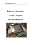
The Tablet Panther DR886EX allows operation under extreme
environmental conditions. All interfaces and slots are covered
separately. The casing is equipped with rubber bumpers and
provides a maximum of protection against shock, vibration, dust and
humidity. The technical details are listed in chapter 3 Specifications.
The following lists the standard scope of delivery for the notebook.
Please use this list to check the package contents for completeness.
Contact dealer if one or more of the following listed items are not
contained in the package.
power cable
external power supply unit
driver CD
tablet computer Panther DR886EX
battery (may be installed)
Figure 1: Panther DR886EX scope of delivery
—————————————————————————
Page 16 of 110
Panther DR886EX User Manual
roda
—————————————————————————
1.2
View
Note: Some functions are optional.
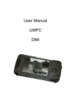
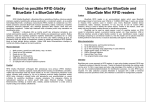
1.2.1
Front view
Figure 2: Front view
F1~F6:
Fn:
Function keys, blue font are alternative functions enabled
by pressing Fn and the key simultaneously
To enable alternative function keys
:
Sleep button (refer “Timeout/Standby/Wake up”)
:
Display brightness decrease
:
Display brightness increase
:
Power button (refer “Timeout/Standby/Wake up”)
:
Battery charge/Heater activity indicator
ON:
Charging
OFF:
Battery full (off if no battery intalled)
Flash:
Heater active (heater is an optional device)
:
HDD (Hard Disk Drive) activity indicator
:
Power indicator
—————————————————————————
Page 17 of 110
Panther DR886EX User Manual
roda
—————————————————————————
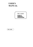
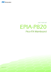
1.2.2
Rear view
1
2
Figure 3: Rear view
3
1.
2.
3.
4.
4
secondary battery connector
roda label with serial number
roda type label
Windows licence label (optional)
—————————————————————————
Page 18 of 110
Panther DR886EX User Manual
roda
—————————————————————————
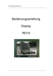
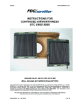
1.2.3
Left-side view
Figure 4: Left-side view
1
1.
2.
3.
4.
1.2.4
2
3
4
Battery
LAN
USB
PCMCIA Slot
Right-side view
Figure 5: Right-side view
1
2
1. DC jack (2 pin for DR886EX/AC-I, 3 pin for DR886EX/AC-M)
2. Serial port (COM1)
—————————————————————————
Page 19 of 110
Panther DR886EX User Manual
roda
—————————————————————————
1.2.5
Top view
Figure 6: Top view
1
1.
2.
3.
4.
1.2.6
2
3 4
Antenna (optional)
GPS/WLAN/Antenna/Camera module
HDD
Kensington lock slot
Bottom view
Figure 7: Bottom view
1
2
3
1. Warranty seal
2. Docking connector
3. External antenna jack (optional)
—————————————————————————
Page 20 of 110
Panther DR886EX User Manual
roda
—————————————————————————
1.3
Preparing the notebook for commissioning
Insert the battery module into the battery module slot and
tighten the safety screw.
Note: Please use a coin to turn the screw. Using screwdrivers
might damage the screw or case.
Connect the line cable with the power-supply unit and plug
the plug into the electrical outlet.
Note: The enclosed line cable complies with the specifications of
the country in which the tablet was purchased. Please ensure
that the line cable has been approved for the country in which the
notebook will be used. Find further information on countryspecific power plug version in the Annex.
Plug the DC plug of the power-supply unit into the DC input
of the tablet and tighten the knurled screw.
Charge the tablet for at least 10 minutes.
Note: There is no memory effect with the used Lithium-Ion
batteries. It is not necessary to discharge the battery completely.
Turn the Panther DR886EX on by pressing the power button
.
Turn OFF the computer using either one of the following
procedures:
o Press power button for 4 seconds to have a “Hard”
power off.
System shuts down without saving any data or parameters
o
Press power button momentarily to “Standby” or “Hibernate”
dependent on operating system (OS) and power scheme
settings.
—————————————————————————
Page 21 of 110
Panther DR886EX User Manual
roda
—————————————————————————
Note: Some operating systems may not support these functions.
If you are using Microsoft Windows operating system click
Start Shutdown or press the Windows button (you will
need an external keyboard to do so) to turn the computer off.
o
Note:
In temperatures below 0°C (32°F), the tablet may not
boot immediately.
while the notebook is
The system will create a signal
heating up. After 13 to 15 minutes, the notebook will have
reached its minimum temperature and boot automatically.
If required, you may skip the heating-up phase by
pressing the power-on button for about 10 seconds; the
system will then boot immediately. However, it cannot be
guaranteed that all components will function seamlessly
with power-on method.
Driver or application software installation may be necessary for
further operation.
—————————————————————————
Page 22 of 110
Panther DR886EX User Manual
roda
—————————————————————————
1.4
Power-On Self Test (POST)
Figure 8: Post screen
Shortly after the switching on the tablet, a series of information will be
displayed on the screen. You may now Press [F2] to start the BIOS
setup of the Panther DR886EX. Check chapter BIOS Setup for
further information.
The system will now run a Power-On Self Test (POST). During this
test the main tablet components are checked:
processor
memory
interrupt controller
inputs and outputs
DMA controller, clock unit and video controller
As part of this self test, the current hardware configuration is
compared with the system’s configuration data stored in the batterybased CMOS-RAM. In addition, all hardware components are
routinely checked. If during the power-on self test a deviation from
the current configuration and/or a hardware error is detected, the
tablet will automatically ask you with a message to start the Setup
service program (see chapter 4 BIOS Setup).
—————————————————————————
Page 23 of 110
Panther DR886EX User Manual
roda
—————————————————————————
1.5
Installing the Windows operating system
When you switch on the Panther DR886EX for the first time, the
Microsoft Windows XP start screen will appear.
Follow the instructions on the screen.
When switching on the computer for the first time, the enclosed
software will be installed and configured. Since this process may not
be interrupted, you should allow some time for it and should leave the
notebook connected to the line voltage via the mains adapter. During
installation, you may only reboot the Panther DR886EX when
requested to do so.
Note: Only applies, if an installed Windows XP was part of delivery.
1.6
Adjusting screen brightness
You can adjust LC display brightness to your needs with the following
keys:
Increase brightness:
Reduce brightness:
—————————————————————————
Page 24 of 110
Panther DR886EX User Manual
roda
CHAPTER 2
—————————————————————————
Components and
Operations
—————————————————————————
Page 25 of 110
Panther DR886EX User Manual
roda
—————————————————————————
2
Components and Operation
2.1
Location
A clean and moisture-free environment is preferred. Make room for
air circulation.
Avoid areas with:
Sudden or extreme changes in temperature.
Extreme heat.
Strong electromagnetic fields (near television set, motor
rotation area, etc.).
Dust or high humidity.
If it is necessary to work in a hostile environment, please regularly
maintain your computer by cleaning dust, water, etc. to keep it in
optimal condition.
2.2
Ruggedness
The computer is designed with rugged features as vibration, shock,
dust, and rain/water protection. However, it is still necessary to
provide appropriate protection while operating in harsh environments.
NEVER immerse the computer completely in water. Doing so may
cause permanent damages. Drop may cause parts break or
permanent damages.
The D-sub connector cap is for dust and shock protection only. The
connector itself is sealed internally. Other I/O ports and devices must
have caps tightly closed or cable inlets sealed while exposed to water
or dust.
All connectors will corrode if exposed to water or moisture. Corrosion
is accelerated if the power is ON. Please take proper measures in
cable connection to avoid water entering into connectors. The DC
jack and cables are sealed and may be operated with water
splashing while attached. All port covers should be in place when no
cable is attached.
—————————————————————————
Page 26 of 110
Panther DR886EX User Manual
roda
—————————————————————————
2.3
Operating Systems
The computer is compatible with most operating systems (OS).
However, not all functions are 100% compatible.
For example, ACPI, APM, Smart Battery, etc. are not available on
DOS, Windows NT, and other non-Microsoft OS. Consequently
“Standby”,
Note:
ACPI: Advanced Configurations and Power Interface
APM: Advanced Power Management
2.4
Power supply for the Panther DR886EX
The Panther may be power supplied either via the mains adapter or
the integrated battery. Optionally, a DC/DC converter is available; it
can be used to operate the tablet via a vehicle or similar battery.
2.4.1
Mains adapter
Figure 9 Mains adapter
The enclosed mains adapter automatically adjusts to the line voltage
of the respective country. Make sure you have the correct countryspecific power-plug version (see Annex B).
The mains adapter supplies the connected tablet with power and
charges the integrated Lithium-Ion battery. The green operation LED
—————————————————————————
Page 27 of 110
Panther DR886EX User Manual
roda
—————————————————————————
illuminates as soon as the adapter is connected with the power line,
regardless whether the adapter is connected with the tablet.
For power supply to the Panther DR886EX, only use original
manufacturer parts provided for this tablet. Otherwise you
may cause damage to the notebook and/or externally
connected peripherals. Moreover, the manufacturer’s
warranty will forfeit if you ignore these instructions
2.4.2
Battery operation
The exchangeable Lithium-Ion battery is the tablet’s main power
source when the mains adapter is not connected. As a standard, the
Panther DR886EX is equipped both with a primary and a real-time
clock (RTC) battery.
You may choose to purchase an additional battery for longer, powerline-independent operation. This additional battery can be mounted
on the rear side.
Figure 10: Battery
RTC-Battery
The RTC (Real Time Clock) battery provides power to the integrated
real-time clock and the calendar even when the notebook is switched
off and not connected with the mains adapter. In addition, the RTC
—————————————————————————
Page 28 of 110
Panther DR886EX User Manual
roda
—————————————————————————
battery is responsible for maintaining the system settings in BIOS.
The RTC battery is also charged via the connected mains adapter. In
order to avoid losing system settings when the tablet is not used for a
longer period of time, you should connect the tablet with the mains
adapter for a few hours a least once a month. When commissioning
the tablet, please make sure that date and time settings are correct;
otherwise, you will need to adjust them.
Note: If required, the RTC battery installed in the notebook should
only be replaced by authorised service staff, since it requires
opening the tablet.
Primary battery
The Panther’s primary battery is made up of 9 Lithium-Ion cells.
Before the battery is operated for the first time, the battery should be
fully charged.
Charging the battery
After connecting the notebook with the mains adapter and power line,
the battery will charge. The tablet can either be switched on or off
during this process. The Panther’s charge indicator
is illuminated
until the battery is fully charged. Upon completion of the charge
process, the indicator LED will switch off. You may now use the tablet
without power-line supply.
Monitoring battery capacity
If the tablet operates with the battery, you may monitor the remaining
battery energy as follows in the Windows operation system:
Click on “Battery” symbol in the task bar, or in Windows system
control, on the “Energy” symbol.
The following window will inform you on he charge status of the
integrated battery/batteries.
—————————————————————————
Page 29 of 110
Panther DR886EX User Manual
roda
—————————————————————————
Figure 11: Energy options (German)
Battery – Warnings
The Panther DR886EX is equipped with acoustic and optical
warnings to inform you when battery capacity is coming to an end.
These warnings should tell you to store your work as soon as
possible in order not to lose any data.
Note: The following information refers to the standard settings in
the Windows XP operating system. If another operating system is
installed, the energy settings may not function properly. This
particular applies to Windows NT and operating systems that are
not Windows based.
Warning with low battery-charge state
If the remaining battery power drops under 10% of the overall
capacity, the tablet will inform you about this situation as follows in
the standard settings:
A one-Time signal will sound
—————————————————————————
Page 30 of 110
Panther DR886EX User Manual
roda
—————————————————————————
A text will be displayed that warns you of low battery-charge
state
The tablet will remain switched on. As this time, you should
immediately store your work, since battery power will last for another
5 to 10 minutes only.
Warning with critical battery-charge state
If the remaining battery power has reached a rest capacity of 5%, the
tablet will automatically carry out the following measures in the
standard settings:
A one-time signal will sound
A text will be displayed that warns you of critical batterycharge state
The tablet will switch to idle state
If you have not done so, you must now connect the tablet with the
mains adapter or replace the low battery with a fully charged one.
If you switch on the Panther DR886EX after the automatic shutdown,
note, that the battery will allow operation for a very short time. During
the last minutes of battery power, the battery-charge state indicator
will indicate this critical state.
Note: Battery performance and lifecycle depend on a number of
factors, such as ambient temperature, age, number of charge and
discharge cycles, etc.
Using the energy-saving mode
If you operate the tablet with a battery, you may choose to use
different energy-saving functions in order to extend operation time.
Among other things, the duration of the battery depends on the
following factors:
—————————————————————————
Page 31 of 110
Panther DR886EX User Manual
roda
—————————————————————————
Processor type and CPU clock frequency
Screen brightness
LCD switch-off
Frequency and duration of access to the hard disk and
optical drives
Initial battery-charge status
Usage intensity of connected and inserted additional devices,
such as USB devices or Express cards that are powered via
the battery
Setting the energy-saving functions
Windows XP
Under Start System control Performance and maintenance
Energy options, you can set the tablet’s energy-saving functions.
Windows Vista
Under Start symbol System control Mobile PC Energy
options, you can set the tablet’s energy-saving functions.
Other operating systems
If you use other operating systems, ask the manual, distributor or
developer for energy-saving functions. You may use BIOS based
energy-saving functions.
You can configure the tablet in the way, that, e.g., the hard disk drive
or screen shut down after a defined period of time.
In addition to the regular operation mode, in which different devices
may be shut down, the notebook has two different energy-saving
levels: standby mode and idle state.
—————————————————————————
Page 32 of 110
Panther DR886EX User Manual
roda
—————————————————————————
Standby mode
If you wish to briefly interrupt your work, you may switch off the tablet
without closing the application. In standby mode, the LCD is switched
off, the hard disk drive shuts down and the processor is clocked to a
very low frequency. The tablet’s RAM continues to be supplied with
energy so that all the information remains in the RAM. When you turn
the notebook back on, you can continue your work where you left off.
Idle State
When idle state is activated, all data in the tablet’s RAM and the
information on the screen are stored on the hard disk drive.
Thereafter, the tablet shuts down. Depending on the open programs,
this process may take a few seconds.
Note: Activating standby mode will save energy, when you switch
the notebook on and off frequently. If you do not use the tablet for a
long period of time, end the energy-saving mode and switch off the
notebook.
2.5
Shutdown
The following procedure is recommended in shutting down the
computer:
Save any work you want to keep
Make sure none of the disk drives are active (HDD, FDD,
CD-ROM, DVD)
Remove any diskettes, CD-ROMs, or other Media
Follow the shut down procedure of you Operating System
Failure to shut down the computer properly may result in loss of data
or hardware damages.
Automatic shut down is activated at battery exhaust. Be sure to finish
your work and save all your data when the battery low warning
appears.
—————————————————————————
Page 33 of 110
Panther DR886EX User Manual
roda
—————————————————————————
2.6
Safe Guard the Computer
Figure 12: Kensington lock
Plug the Kensington lock into the slot near HDD and turn lock it. Both
the computer and HDD are secured.
—————————————————————————
Page 34 of 110
Panther DR886EX User Manual
roda
—————————————————————————
2.7
Replacing Modules
To remove the modules:
Turn OFF the computer and remove all cables from the
computer. Do not use Hibernate or Standby mode
Use a coin to turn loose the screws on the modules
Remove battery from the compartment
Remove the HDD from he computer
Be sure to turn OFF the computer before replacing any
module!
Figure 13: Replaceable modules
2.8
Re-install Modules
Gently push the module into the slot. Fasten the screw to fix the
module. Make sure the O-rings are firmly fixed. No sealant is
necessary for the O-rings.
—————————————————————————
Page 35 of 110
Panther DR886EX User Manual
roda
—————————————————————————
2.9
Components
2.9.1
Hard Disk Drive
Figure 14: Hard disk drive case
The Hard Disk Drive (HDD) is a 2.5” type standard SATA interface
data storage device. Capacity of the HDD may vary. The HDD is
removable. This provides convenience and security. It can ONLY be
removed while power is OFF.
NEVER drop your HDD module or expose it to high
temperature, high humidity, or any hazardous environment.
NEVER try to disassemble the module. Static discharge may
destroy your device and data. Always pick up the modules by
touching the case only.
—————————————————————————
Page 36 of 110
Panther DR886EX User Manual
roda
—————————————————————————
2.9.2
Touch Screen
Panther DR886EX comes with an integrated touch screen. It
facilitates direct pen input on the screen instead of mouse or touch
pad. Please use the pen delivered together with the Panther and do
not use your fingers to operate the touch screen. Fat naturally
produced by the body may soil the touch screen, decreasing input
accurateness and display quality. Use the driver software to calibrate
the touch screen.
Figure 15: Touch screen calibration
Use the touch screen by moving with the pen over the surface of the
touch screen. The mouse curser will follow your movements. You can
perform a one-time click by briefly tipping on the touch screen once, a
double click by tipping on the touch screen twice. Drag and drop is
also possible, by tipping a symbol, holding it, and moving the pen in
the respective direction.
2.9.3
Interfaces
PCMCIA
The computer supports 2x type-II PCMCIA card or 1x type-II PCMCIA
card and 1x Express Card. To remove the card, push the eject
button. The eject button can hide into the compartment by pushing it
inward gently. The PCMCIA slots are on the left side of the Panther
DR886EX.
—————————————————————————
Page 37 of 110
Panther DR886EX User Manual
roda
—————————————————————————
USB
Also on the left side, an USB 2.0 interface is located. Remove the
rubber cap to access it. The interface is compatible with USB 1.1.
RJ45
Next to the USB interface there is a RJ45 Interface for Ethernet
connections. The interface is able to support 10/100/1000 Mbit/s
Ethernet, depending on the configuration of the Panther DR886EX.
Sub D-9 (COM1)
On the right side of the Panther is the COM1 Port. It is a Sub D-9
interface for RS232 (standard configuration).
DC jack
The last connector on the right side is the DC jack. It can be a 3pin
(DR886EX/AC-M military) or 2pin (DR886EX/AC-I industrial) jack.
Only connect the mains adapter provided by roda computer
GmbH to this jack.
2.9.4
Docking connector
On the bottom side the Docking connector is located. You can
connect a DockLite or an adapter cable to this connector to increase
the amount of available interfaces.
Note: To avoid malfunctions keep all covers closed so the
interfaces will not be damaged and/or polluted.
—————————————————————————
Page 38 of 110
Panther DR886EX User Manual
roda
—————————————————————————
2.10
Optional components
2.10.1 External Backlight Keyboard
The external backlight keyboard is equivalent to a full size desktop
keyboard plus extra functions. The interface is via USB port or PS/2.
Figure 16: External backlight keyboard (USB)
Track Point:
The track point is functionally equivalent to a mouse. Pushing the
track point may move the cursor on the screen. The 2 buttons act
same as mouse buttons.
Backlight:
Pressing [I-O] key for approximately 1 second turns keyboard
backlight ON or OFF.
—————————————————————————
Page 39 of 110
Panther DR886EX User Manual
roda
—————————————————————————
2.10.2 Floppy Disk Drive (FDD)
The USB 3.5” 1.44MB floppy disk drive (FDD) is almost same as
conventional 3.5” FDD. The difference is interface via USB- To use
FDD the operating system must support USB.
2.10.3 CD-ROM/DVD Drive
CD-ROM/DVD drive is also an USB device. The interface
requirement is same as FDD. As USB function is active after
Windows boot up, Windows installation via USB CD-ROM is not
possible even the Windows itself supports USB. Audio CD output is
via the audio jack on CD-ROM drive only.
2.10.4 Memory Card
The memory card will expand main memory to facilitate better system
performance. The cards are available as following:
512 MB
1 GB
2 GB
Maximum memory is 4 GB. Please note 32 bit operating system can
only provide ca. 3.3 GB of memory. Around 700 MB will be reserved
for addressing.
2.10.5 LAN Card
Panther DR886EX can be equipped with 10/100/1000 Gbit/s Ethernet
LAN cards.
2.10.6 Wireless LAN
IEEE 802.11a,b,g wireless LAN card and rugged antenna are
available.
—————————————————————————
Page 40 of 110
Panther DR886EX User Manual
roda
—————————————————————————
2.10.7 MDC Modem Card
V.90 56K Fax/Modem can be added to the Panther’s configuration.
2.10.8 Second Battery
A Lithium-Ion rechargeable second battery may mount on the rear. It
has 1.5 times capacity of primary battery and same Smart Battery
compliance. The computer’s internal charger can detect the second
battery and perform charging accordingly.
2.10.9 Vehicle Adapter
Converting power from car lighters (12~14V) or truck batteries
(24~28V). It can
power the system and charge the batteries simultaneously.
2.10.10 Heater
Built-in heater and control circuit activates heating when computer is
turned ON
at temperature 0°C~-20°C (32°F~-4°F). The heating is automatically;
just turn ON power the heater controller will detect temperature and
take over. The power indicator flashes while heating. The computer
will boot up when the internal temperature reaches safe level. It may
take 5~20 minutes depends on how cold the temperature is. For
temperature below –20°C (-4°F) the computer may never heat up.
Plug in AC or vehicle adapter for heating as battery power may
become very low at low temperature.
2.10.11 Dual Battery Charger
The charger provides two slots for the Primary and Secondary battery
respectively. It allows charging of both batteries simultaneously and
accepts power from AC adapter or Vehicle adapter. It takes
approximately 3~4 hours to fully charge both batteries.
—————————————————————————
Page 41 of 110
Panther DR886EX User Manual
roda
—————————————————————————
2.10.12 Stand Unit
Stand unit can hold the system unit and DockLite with adjustable
view angle. It can be used in office or in vehicle.
There are two configuration options:
Stand unit only to accept system unit
Stand unit with DockLite hooked to accept system unit
Mount Stand Unit:
Open the rubber cap on the docking connector
Align the computer into stand unit
Push the lever to engage and fix
Lock the computer
Add DockLite e.g.
2.10.13 DockLite
DockLite acts as docking unit or port enhancer. It contains more ports
than the Panther DR886EX itself. Different configurations of DockLite
are available.
Mount DockLite:
Open the rubber cap on the docking connector
Align the docking connector
Attach DockLite
Fix the screws
—————————————————————————
Page 42 of 110
Panther DR886EX User Manual
roda
—————————————————————————
DockLite Industrial View
Top View:
Figure 17: DockLite top view
1
1. Docking connector
Front View:
S
1
2
3
4
5
6
7
8
Figure 18: DockLite front view
1.
2.
3.
4.
5.
6.
7.
8.
9.
S
Audio jacks (Microphone/Speaker)
RGB port
Modem jack (RJ11)
LAN jack (RJ45)
Serial port (COM3)
USB port 1,2 (standard type)
USB port 3,4 (proprietary sealed type)
Serial port (COM2)
DC jack
Screws
—————————————————————————
Page 43 of 110
S
Panther DR886EX User Manual
roda
—————————————————————————
DockLite Military View
Front View:
S
1
2
3
4
5
6
S
Figure 19: DockLite MIL
1.
2.
3.
4.
5.
6.
S
X5 interface (Ethernet)
X6 interface (DVI)
Serial port (Sub-D9 RS232)
X8/X9 interface (USB option)
X10 interface (RS232)
X11 interface (DC jack)
Screws
—————————————————————————
Page 44 of 110
Panther DR886EX User Manual
roda
CHAPTER 3
—————————————————————————
Specifications
—————————————————————————
Page 45 of 110
Panther DR886EX User Manual
roda
—————————————————————————
3
Specifications
3.1
Components
3.1.1
System Unit
Component
CPU
Level 2 Cache
Video Memory
North Bridge
South Bridge
RAM
VGA
Touch Screen
HDD
LAN card
Sound
Buttons (front)
Interfaces (left)
Interfaces (right)
Interfaces (rear)
Interfaces (bottom)
Interfaces (internal)
Primary battery
Power input
Dimensions
Weight
Case
Color
Environmental
Panther DR886EX
Intel Core2 Duo (ULV) U7500 1.1GHz
2MB
224MB (shared Memory)
Intel 945GM/GME
Intel 82801GHM ICH7
1GB ~ 4GB 400MHz
8.4“ XGA (1024x768 Pixel)
Brightness: 300 cd/m² Contrast: 400
Resistive polarized
Transparency: > 80%
Swappable 2.5“ SATA HDD
Realtek
AC97 sound with Speaker
ON/OFF, LCD Brightness up/down,
Standby, F1 – F6 & Fn
2x PCMCIA Type II or 1x PCMCIA Type II
und PCMCIA Express
1x USB
1x RJ45
DC jack (2Pin/3Pin), Serial Port Sub D-9
Secondary battery connector
Docking Connector
Mini PCI x 1, Mini PCI express x 1, USB
2.0 x 4, IEEE1394 x 2, Serial x 2 (TTL x
2, RS232 x 1)
11.1V/4800mAH Lithium-Ion Battery
DC 12V ~ 32V
250mm x 190mm x 46mm
1.9 Kg (depends on configuration)
Magnesium
black/NATO green
MIL-STD-810, IP54
Table 1: DR886EX components
—————————————————————————
Page 46 of 110
Panther DR886EX User Manual
roda
—————————————————————————
3.1.2
AC adapter
Features
Input: AC 100V ~ 240V 50/60Hz (47Hz~63Hz)
Output: DC 19V ± 1V, max. 90W
Also complies with military power source100V ~
240V 400Hz
Dimensions: 133mm x 58mm x 30mm
Weight: 400g
Table 2: AC adapter (mains adapter)
3.1.3
Options
Component
Secondary Battery
Modem
WLAN
GPS
HSDPA
Bluetooth
RS422/RS485
DockLite
Stand Unit
Dual Battery Charger
Isolated System
MIL-STD-461
LAN + Modem (MDC)
LAN + WLAN
LAN + WLAN + Modem
LAN +WLAN + Modem +
HSDPA/CDMA
LAN + WLAN + HSDPA/CDMA
Camera
Panther DR886EX
Available
Available
Available
Available
Available
Available
Available
Available (Industrial or MIL)
Available
Available
Available (not with WLAN)
Available
Available
Available
Available
Available
Available
Available
Table 3: Possible options
Note: Configuration of DockLite may vary.
—————————————————————————
Page 47 of 110
Panther DR886EX User Manual
roda
—————————————————————————
3.1.4
Industry/Military Models Configurations
Component
Case
Rubber jacket
DC power
connector
Operating
temperature
EMC
Industry Model
Black and grey
Black
2 Pin Industry
connector
0°C ~ +40°C
CE, FCC
Military Model
NATO green
Military green
3 Pin Military connector
-20°C ~ +50°C (w Heater)
0°C ~ +50°C (w/o Heater)
CE, FCC, MIL-STD-461
Table 4: Industry/Military models configuration
3.1.5
Primary and secondary Battery
Primary
battery
Secondary
battery
Type: 6x 18650 Lithium-Ion cells
Capacity: 11.1V 4400mAh
Dimensions: 150mm x 58mm x 20 mm
Weight: 300g
Type: 9x 18650 Lithium-Ion cells
Capacity: 11.1V 6600mAh
Dimensions: 150mm x 90mm x 20 mm
Weight: 500g
Table 5: Battery
3.1.6
Keypad/Keyboard
Keypad
(embedded)
Keyboard
(extern)
Function keys: F1 ~ F6
Number of keys: 89
Key travel: 1.5mm
Function: emulates standard 101/102 keys
keyboard
Trackpoint: equivalent to PS/2 or USB
mouse
Table 6: Keyboard/Keypad
—————————————————————————
Page 48 of 110
Panther DR886EX User Manual
roda
—————————————————————————
3.1.7
Vehicle Adapter
Features
Input voltage: 12V/24V (10~32V)
Input current: 2.5A/5.5A max.
Output voltage: 19V ± 5%
Output current: 2.8A
Connector: cigarette lighter, vehicle battery
Weight: 500g
Table 7: Vehicle adapter
3.1.8
Stand Unit
Features
Dimensions: 240mm x 290mm x 150mm
Weight: 1.6Kg
Table 8: Stand unit
3.1.9
Material and Recycling
Component
Plastic Cabinet
Magnesium
Cabinet
Bracket
Material
UL grade PC + ABS GE C2800 or C6200
Magnesium alloy AZ91D
Aluminium 5052
Steel with Nickel plating
Stainless steel S304
Trackpoint, keys
Rubber
Covers
Rubber
PCB
FR-4, UL 94 V0
Battery
Rechargeable Lithium Ion cells
Packing
Carton: Unbleached paper
Cushion: Recyclable PE
Carrying bag: Recyclable PE Fibre
Manual: Paper
Please recycle the parts according to local regulations.
Table 9: Material and recycling
—————————————————————————
Page 49 of 110
Panther DR886EX User Manual
roda
—————————————————————————
3.2
Interfaces
3.2.1
DC jack industry
GND
+19V
Figure 20: DC jack
Machine side: LTWS-02PMMS-LS
Mating plug: LTWAD-02AFFM-LL6000
3.2.2
DC jack military
+19V
CN
GND
Figure 21: DC MIL
Machine side: Amphenol 62GB-12E08-33PN
Mating plug: 62GB-56T08-33SN
—————————————————————————
Page 50 of 110
Panther DR886EX User Manual
roda
—————————————————————————
3.2.3
Serial port
Figure 22: Serial port
Machine side: Sub D-9 jack
Mating plug: Sub D-9 plug
Pin assignment:
Pin
1
2
3
4
5
6
7
8
9
Shell
RS232
/CD
/RXD
/TXD
/DTR
GNR
/DSR
/RTS
/CTS
/RI
GND
RS422
(Option)
TXDTXD+
RXD+
RXDGND
RTSRTS+
CTS+
CTSGND
RS485
(Option)
DataData+
(Data+)
(Date-)
GND
NC
NC
NC
NC
GND
Table 10: Pin assignment serial port
—————————————————————————
Page 51 of 110
Panther DR886EX User Manual
roda
—————————————————————————
3.2.4
RGB port
Figure 23: RGB port
Machine side: Sub D-15 jack
Mating plug: Sub D-15 plug
Pin assignment:
Pin
1
2
3
4
5
6
7
8
9
10
11
12
13
14
15
Assignment DR886EX
RED
GRENN
BLUE
GND
GND
GND
GND
GND
GND
GND
GND
SDA
BHSYNC
BVSYNC
SCL
VESA (for reference)
RED
GREEN
BLUE
RES.
GND
RGND
GGND
BGND
+5V
SGND
ID0
SDA
BHSYNC
BVSYNC
SCL
Table 11: Pin assignment RGB port
—————————————————————————
Page 52 of 110
Panther DR886EX User Manual
roda
—————————————————————————
3.2.5
LAN jack
8
1
Figure 24: LAN jack
Machine side: RJ45 jack
Mating plug: RJ45 plug
Pin assignment:
Pin
1
2
3
4
5
6
7
8
10/100 Mbit/s
LANTX+
LANTXLANRX+
NC
NC
LANRXNC
NC
1000 Mbit/s
LANTX+
LANTXLANRX+
LANTX1+
LANTX1LANRXLANRX1+
LANRX1-
Table 12: Pin assignment LAN jack
3.2.6
USB
Figure 25: USB
Machine side: USB A jack
Mating plug: USB A plug
—————————————————————————
Page 53 of 110
Panther DR886EX User Manual
roda
—————————————————————————
Pin assignment:
Pin
1
2
3
4
Assignment
Vcc
USBUSB+
GND
Table 13: Pin assignment USB
3.2.7
USB (proprietary, sealed on DockLite)
Figure 26: USB (on DL)
Machine side: proprietary lock and sealed USB connector
Mating plug: available via roda
Pin assignment:
Pin
1
2
3
4
Assignment
Vbus (Vcc)
D- (USB-)
D+ (USB+)
GND
Table 14: Pin assignment USB proprietary on DL
—————————————————————————
Page 54 of 110
Panther DR886EX User Manual
roda
—————————————————————————
3.2.8
Docking Connector
4
120
Figure 27: Docking connector
1
117
Machine side: Molex 52755-1200R
Mating plug: Molex 52758-120RR
Pin assignment:
PIN
1
2
3
Assignment
VA
VA
VB
4
VB
5
6
7
VA
P0
VB
8
V_5
9
10
11
12
reserve
P1
POWER_SW
V_5
13
EXT_ANT_MUX
14
15
16
P2
PSD_DDC
V_5
17
GND
Notes
AC input
AC input
Prim. Battery
(res.)
Prim. Battery
(res.)
Pin
61
62
63
Assignment
IDE_PDDREQ
IDE_PDD3
IDE_PDIORDY
Notes
nd
2 IDE
nd
2 IDE
nd
2 IDE
64
V_3
+3.3V
400mA
max.
AC input
1394 interface
Prim Battery
(res.)
+5V 400mA
max.
65
66
67
GND
IDE_PDD4
IDE_PDD6
2 IDE
nd
2 IDE
68
IDE_PDD5
2
69
70
71
72
IDE_PDD7
IDE_PDCS1#
IDE_PDD8
V_3
73
IDE_PDD9
2 IDE
nd
2 IDE
nd
2 IDE
+3.3V
400mA
max
nd
2 IDE
74
75
76
IDE_PDA0
IDE_PDD10
IDE_PDA1
2 IDE
nd
2 IDE
nd
2 IDE
77
IDE_PDD11
2
1394 interface
ON/OFF
+5V 400mA
max.
External
Antenna (res)
1394 interface
DVI (res.)
+5V 400mA
max.
nd
nd
IDE
nd
nd
nd
IDE
—————————————————————————
Page 55 of 110
Panther DR886EX User Manual
roda
—————————————————————————
PIN
18
19
20
Assignment
P3
PSD_DDC
P4
21
22
23
24
25
26
27
28
29
30
31
reserved
P5
reserved
P6
PLAN_BI D3+
P7
PLAN_BI D3reserved
PLAN-BI D4+
PLAN-BI D4RTXD3#
32
RDCD3#
33
GND
34
RDSR3#
35
RCTS3#
36
RRXD3#
37
RDTR3#
38
RRTS3#
39
RRI3#
40
41
Notes
1394 interface
DVI (res.)
1394 interface
Pin
78
79
80
Assignment
IRQ14
IDE_PDD12
V_3
81
82
83
84
85
86
87
88
89
90
91
GND
IDE_PDDACK#
IDE_PDD13
IDE_PDDOIR#
IDE_PDD14
IDE_PDDIOW#
IDE_PDD15
CD_R
IDE_PDCS3#
PLT_RST#
IDE_PDA2
2 IDE
nd
2 IDE
nd
2 IDE
nd
2 IDE
nd
2 IDE
nd
2 IDE
nd
2 IDE
nd
2 IDE
PLT_RST
nd
2 IDE
92
CD_L
2
93
USB_PP2
94
USB_PN2
95
DVI-TXC-
96
DVI-TXC+
DVI (res.)
97
GND
98
VSYNC
99
DVI-TXC2-
DCD3#
TXD3#
COM3
(RS232)
COM3
(RS232)
COM3
(RS232)
COM3
(RS232)
COM3
(RS232)
COM3
(RS232)
COM2 (TTL)
COM2 (TTL)
USB
interface
USB
interface
DVI (res.)
100
101
DVI-TXC2+
EXT_SPK_IN
42
DSR3#
COM2 (TTL)
102
DDC2BD
43
44
45
46
CTS3#
RXD3#
DTR3#
RTS3#
COM2 (TTL)
COM2 (TTL)
COM2 (TTL)
COM2 (TTL)
103
104
105
106
DVI-TXC1DVI-TXC1+
LAN-RX D2DDC2BC
47
48
49
50
51
RI3
GND
GND
Line_inR
EK_CLK
COM2 (TTL)
107
108
109
110
111
DVI-TX0DVI-TX0+
LAN-RX D2+
Ext_SP-Right
Ext-SP-Left
1394 interface
1394 interface
GLAN
1394 interface
GLAN
GLAN
GLAN
COM3
(RS232)
COM3
(RS232)
Sound
PS/2
Keyboard
Notes
nd
2 IDE
nd
2 IDE
+3.3V
400mA
max.
nd
nd
IDE
CRT
(VGA)
DVI (res.)
DVI (res.)
External
Speaker
CRT
(VGA)
DVI (res.)
DVI (res.)
GLAN
CRT
(VGA)
DVI (res.)
DVI (res.)
GLAN
Sound
Sound
—————————————————————————
Page 56 of 110
Panther DR886EX User Manual
roda
—————————————————————————
Pin
52
Notes
Pin
PS/2
112
Keyboard
53
MUCLK
PS/2
113
Mouse
54
PM_SLP_S3#
Suspend
114
(res.)
55
MUDATA
PS/2
115
Mouse
nd
56
IDE_PDD0
2 IDE
116
57
Line_inL
Sound
117
nd
58
IDE_PDD1
2 IDE
118
nd
59
CD-DASP
2 IDE
119
nd
60
IDE_PDD2
2 IDE
120
Table 15: Pin assignment docking connector
3.2.9
Assignment
EK_DATA
Assignment
HSYNC
Notes
CRT (VGA)
LINE-
Modem
LAN-TX D1-
GLAN
MIC-IN
Sound
CRT_R
LINE+
LAN-TX D1+
CRT_G
CRT_B
CRT (VGA)
Modem
GLAN
CRT (VGA)
CRT (VGA)
DockLite MIL
X5 - Ethernet
Figure 28: MIL DL X5
Machine side: Amphenol SJT00RT-08-35SN014
Mating plug: SJTG06RT-08-35PN014
Pin assignment:
Pin
1
2
3
4
5
6
Assignment
TX+
TXRX+
nc
nc
RX-
Table 16: Pin assignment MIL DL X5
—————————————————————————
Page 57 of 110
Panther DR886EX User Manual
roda
—————————————————————————
X6 – DVI
1
37
28
7
12
Figure 29: MIL DL X6
Machine side: Amphenol SJT00GS-14-35SN014
Mating plug: SJTG06GS-14-35PN014
Pin assignment:
Pin
1
2
3
4
5
6
7
8
9
10
11
12
13
14
15
16
17
18
19
Assignment
TDMS TX2 N
TDMS TX2 P
TMDS 2 GND
PWRSW
nc
DDC Clock (SCL)
DDC DATA (SDA)
nc
TDMS TX1 N
TDMS TX1 P
TDMS 1 GND
Speaker left
Speaker right
DVI +5V/50mA
GND
Hot Plug Detect (HTPLG)
TDMS TX0 N
TDMS TX0 P
TDMS 0 GND
—————————————————————————
Page 58 of 110
Panther DR886EX User Manual
roda
—————————————————————————
Pin
20
21
22
23
24
25
26
27
28
29
30
31
32
33
34
35
36
37
Assignment
USB N (TX)
USB P (TX)
GND
TDMS CLK P
TDMS CLK N
COM(n) TX (optional)
COM(n) RX (optional)
nc
COM(n) TX (optional)
GND
GND
nc
nc
nc
nc
nc
nc
nc
Table 17: Pin assignment MIL DL X6
X7 – RS232 port
See Chapter 3.2.4
X8, X9 – USB port
See Chapter 3.2.6
—————————————————————————
Page 59 of 110
Panther DR886EX User Manual
roda
—————————————————————————
X10 – MIL RS232
1
11
7
5
Figure 30: MIL DL X10
Machine side: Amphenol SJT00RT-10-35PN014
Mating plug: SJTG06RT-10-35SN014
Pin assignment:
Pin
1
2
3
4
5
6
7
8
9
10-13
Assignment
/CD
/RXD
/TXD
/DTR
/GND
/DSR
/RTS
/CTS
/RI
nc
Table 18: Pin assignment MIL DL X10
—————————————————————————
Page 60 of 110
Panther DR886EX User Manual
roda
—————————————————————————
X11 – DC
+19V
nc
GND
Figure 31: MIL DL X11
Machine side: Amphenol 62EN-12E8-33P
Mating plug: 62GB-56T08-33SN
3.3
Environmental Ratings
3.3.1
MIL-STD-810
Item
Low pressure
(Altitude)
Test Criteria
According to MIL-STD-810F, Method 500.4 procedure I, II
Operating : 4.572m (15,000ft)
Non Operating : 12.180m (40,000ft
High
temperature
According to MIL-STD-810F, Method 501.4 procedure I, II
Low temperature
According to MIL-STD-810F, Method 502.4 procedure I, II
Operating : +50°C (+122°F)
Non Operating : +70°C (+158°F)
Operating : -20°C (-4°F) with heater (0°C without
heater)
Non Operating : -40°C (-40°F)
Temperature
shock
According to MIL-STD-810F, Method 503.4 procedure I
Rain
According to MIL-STD-810F, Method 506.4 procedure I
Operating : -20°C ~ +60°C (-4°F ~ +140°F)
Operating : 276kPa (40 psig), 5 surfaces, 40
minutes/surface
—————————————————————————
Page 61 of 110
Panther DR886EX User Manual
roda
—————————————————————————
Item
Humidity
Test Criteria
According to MIL-STD-810F, Method 507 procedure I
Salt Fog
Vibration
Shock
Operating : (Aggravated) 24 hours/cycle, total of 10
cycles Between 30°C (86°F) and 60°C (140°F) with
the relative humidity at 95% constant)
According to MIL-STD-810F, Method 509.4 procedure I
Non Operating: Salt concentration of 5+-1%, 24 hours wet +
24hours dry/cycle. Total of 2 cycles/96 hours
1. According to MIL-STD-810D, Method 514.3 category 1
Tracked
vehicle vibration
Operating : M548 tracked vehicle
2. According to MIL-STD-810D, Method 514.5 category 14
procedure I
Helicopter vibration OH58A/C
Operating : OH58A/C helicopter
3. According to MIL-STD-810D, Method 514.5 category 20
procedure I
Composite wheeled vehicle vibration
Operating : Figure 514.5C-3 and Table 514.5C-VII
According to MIL-STD-810F, Method 516.5 procedure I
Operating : Figure 516.5-10, Table 516.5C-II, 40g,
11ms, terminal-peak saw tooth shock pulse
Solar radiation
According to MIL-STD-810F, Method 505.4 procedure I
Non Operating : Diurnal cycle A1 worldwide
deployment
Explosive
Atmosphere
According to MIL-STD-810F, Method 511.4 procedure I
Operating test
Table 19: MIL-STD-810
3.3.2
IEC IP
Standards
IEC 60529 IP5x
Dust-tight
IEC 60529 IPx4
Water spray (water jet)
Parameters
Powder type: Talcum
Dust quantity: 2kg
Chamber size: 1m³
Test duration: 8h
Tube radius: 400mm
Water flow: 1.8l/min
Number of open holes: 25
Test duration: 10min
Table 20: IEC IP
—————————————————————————
Page 62 of 110
Panther DR886EX User Manual
roda
—————————————————————————
3.3.3
MIL-STD-461
Standards
MIL-STD-461E
(M-models only)
Parameters
CE102: Conducted Emissions, Power Leads,
10KHz~10MHz
CS101: Conducted Susceptibility, Power Leads,
30Hz~150KHz
CS114: Conducted Susceptibility, Bulk Cable Injection,
10KHz~200MHz
CS115: Conducted Susceptibility, Bulk Cable Injection,
Impulse
Excitation
CS116: Conducted Susceptibility, Damper Sinusoidal
Transients, Cable and Power Leads, 10KHz to
100MHz
RE101: Radiated Emissions, Magnetic Field,
30Hz~100KHz
RE102: Radiated Emissions, Electric Field, 10KHz~18GHz
RS101: Radiated Susceptibility, Magnetic Field,
30Hz~100KHz
RS103: Radiated Susceptibility, Electric Field,
2MHz~40GHz
Table 21: MIL-STD-461
—————————————————————————
Page 63 of 110
Panther DR886EX User Manual
roda
CHAPTER 4
—————————————————————————
BIOS Setup
—————————————————————————
Page 64 of 110
Panther DR886EX User Manual
roda
—————————————————————————
4
BIOS Setup
Press [F2] at boot up to enter BIOS setup. Use arrow keys to select
options and [+/-] to modify them. When finished, move to ”Exit” and
press [Enter] then confirm save by pressing [Y].
Note: The contents
configurations.
4.1
may
vary
depending
on
computer
The General Help Window
Pressing <F1> or <Alt-H> on any menu brings up the General
Help window that describes in detail the keys and functions for
setup. The scroll bar on the right of any window indicates that
there is more than one page of information in the window. Use
<PgUp> and <PgDn> to display all the pages. Pressing <Home>
and <End> displays the first and last page. Pressing <Enter>
displays each page and then exits the window. Press <Esc> to
exit the current window.
4.2
Main Menu
Phoenix TrustedCore(tm) Setup Utility
Main
Advanced
Security
TPM State
[16:19:20]
[03/02/2007]
Legacy Diskette A:
[1.44/1.25MB 3½"]
[None]
[None]
• SATA Port 0
[None]
• SATA Port 1
[None]
System Memory:
F1 Help
Esc Exit
↑↓ Select Item
↔ Menu
Exit
Item Specific Help
System Time:
System Date:
• IDE Channel 0 Master
• IDE Channel 0 Slave
Boot
<Tab>, <Shift-Tab>, or
<Enter> selects field
640 KB Extended Memory:
522752 KB
–/+
Enter
Change Values
Select ► Sub-Menu
F9 Setup Defaults
F10 Save and Exit
Table 22: BIOS main menu
—————————————————————————
Page 65 of 110
Panther DR886EX User Manual
roda
—————————————————————————
Main Menu Selections
You can make the following selections on the Main Menu. Use the
sub menus for other selections.
Feature
Options
System Time
HH:MM:SS
System Date
MM/DD/YYYY
Diskette 1
3 ½" 1.44MB,
Disabled
System Memory
N/A
Extended
Memory
N/A
Description
Set the system time
Hour, Minute, Second.
Set the system date
Month, Day, Year.
Select the type of
floppy-disk drive
installed in your system.
Displays amount of
conventional memory
detected during boot up.
Displays the amount of
extended memory
detected during boot up.
Table 23: Main menu options
4.3
IDE Channel 0 Master Sub-Menu
Phoenix TrustedCore(tm) Setup Utility
Main
Advanced
Security
IDE Channel 0 Master
TPM State
[None]
Type:
[Auto]
Multi-Sector Transfers:
LBA Mode Control:
32 Bit I/O:
Transfer Mode:
Ultra DMA Mode:
[Disabled]
[Disabled]
[Disabled]
[Standard]
[Disabled]
F1 Help
Esc Exit
↑↓ Select Item
↔ Menu
–/+
Enter
Boot
Exit
Item Specific Help
User = you enter
parameters of hard-disk
drive installed at this
connection.
Auto = autotypes harddisk drive installed here.
CD-ROM = a CD-ROM
drive is installed here.
ATAPI Removable =
removable disk drive is
installed here.
Change Values
Select ► Sub-Menu
F9 Setup Defaults
F10 Save and Exit
Table 24: IDE channel 0 master sub-menu
—————————————————————————
Page 66 of 110
Panther DR886EX User Manual
roda
—————————————————————————
IDE Channel 0 Master Sub-Menu Selections
You can make the following selections on the IDE Channel 0 Master
sub menu.
Feature
Type
Options
Auto
None
ATAPI Removable
CD-ROM
IDE Removable Other
ATAPI
User
32 Bit I/O
Disabled
Enabled
Description
Auto = autotypes hard-disk
drive installed here.
None
ATAPI Removable =
removable disk drive is
installed here
CD-ROM = a CD-ROM drive
is installed here
IDE Device
Other ATAPI
User = you enter parameters
of hard-disk drive installed at
this connection
This setting enables or
disables 32 bit IDE data
transfers.
Table 25: IDE channel 0 master sub-menu selections
—————————————————————————
Page 67 of 110
Panther DR886EX User Manual
roda
—————————————————————————
4.4
IDE Channel 0 Slave Sub-Menu
Phoenix TrustedCore(tm) Setup Utility
Main
Advanced
Security
TPM State
IDE Channel 0 Slave
[None]
Type:
[Auto]
Multi-Sector Transfers:
LBA Mode Control:
32 Bit I/O:
Transfer Mode:
Ultra DMA Mode:
[Disabled]
[Disabled]
[Disabled]
[Standard]
[Disabled]
F1 Help
Esc Exit
↑↓ Select Item
↔ Menu
–/+
Enter
Boot
Exit
Item Specific Help
User = you enter
parameters of hard-disk
drive installed at this
connection.
Auto = autotypes harddisk drive installed here.
CD-ROM = a CD-ROM
drive is installed here.
ATAPI Removable =
removable disk drive is
installed here.
Change Values
Select ► Sub-Menu
F9 Setup Defaults
F10 Save and Exit
Table 26: IDE channel 0 slave sub-menu
IDE Channel 0 Slave Sub-Menu Selections
You can make the following selections on the IDE Channel 0 Slave
sub menu.
Feature
Type
Options
Auto
None
ATAPI Removable
CD-ROM
32 Bit I/O
IDE Removable Other
ATAPI
User
Disabled
Enabled
Description
Auto = autotypes hard-disk
drive installed here.
None
ATAPI Removable =
removable disk drive is
installed here
CD-ROM = a CD-ROM drive
is installed here
IDE Device
Other ATAPI
User defined
This setting enables or
disables 32 bit IDE data
transfers.
Table 27: IDE channel 0 slave sub-menu selections
—————————————————————————
Page 68 of 110
Panther DR886EX User Manual
roda
—————————————————————————
4.5
SATA Port 0 Sub-Menu
Phoenix TrustedCore(tm) Setup Utility
Main
Advanced
Security
SATA Port 0
TPM State
[None]
Type:
[Auto]
Multi-Sector Transfers:
LBA Mode Control:
32 Bit I/O:
Transfer Mode:
Ultra DMA Mode:
[Disabled]
[Disabled]
[Disabled]
[Standard]
[Disabled]
F1 Help
Esc Exit
↑↓ Select Item
↔ Menu
–/+
Enter
Boot
Item Specific Help
User = you enter
parameters of harddisk drive installed at
this connection.
Auto = autotypes harddisk drive installed
here.
CD-ROM = a CD-ROM
drive is installed here.
ATAPI Removable =
removable disk drive is
installed here.
Change Values
Select ► Sub-Menu
F9 Setup Defaults
F10 Save and Exit
Table 28: SATA port 0 sub-menu
SATA Port 0 Sub-Menu Selections
You can make the following selections on the SATA Port 0 sub menu.
Feature
Type
Options
Auto
None
ATAPI
Removable
CD-ROM
32 Bit I/O
IDE Removable
Other ATAPI
User
Disabled
Enabled
Description
Auto = autotypes hard-disk
drive installed here.
None
ATAPI Removable =
removable disk drive is
installed here
CD-ROM = a CD-ROM
drive is installed here
IDE Device
Other ATAPI
User defined
This setting enables or
disables 32 bit IDE data
transfers.
Table 29: SATA port 0 sub-menu selections
—————————————————————————
Page 69 of 110
Panther DR886EX User Manual
roda
—————————————————————————
4.6
SATA Port 1 Sub-Menu
Phoenix TrustedCore(tm) Setup Utility
Main
Advanced
Security
SATA Port 1
TPM State
[None]
Type:
[Auto]
Multi-Sector Transfers:
LBA Mode Control:
32 Bit I/O:
Transfer Mode:
Ultra DMA Mode:
[Disabled]
[Disabled]
[Disabled]
[Standard]
[Disabled]
F1 Help
Esc Exit
↑↓ Select Item
↔ Menu
–/+
Enter
Boot
Item Specific Help
User = you enter parameters of
hard-disk drive installed at this
connection.
Auto = autotypes hard-disk
drive installed here.
CD-ROM = a CD-ROM drive is
installed here. ATAPI
Removable = removable disk
drive is installed here.
Change Values
Select ► Sub-Menu
F9 Setup Defaults
F10 Save and Exit
Table 30: SATA port 1 sub-menu
SATA Port 1 Sub-Menu Selections
You can make the following selections on the SATA Port 1 sub menu.
Feature
Type
Options
Auto
None
ATAPI Removable
CD-ROM
32 Bit I/O
IDE Removable Other
ATAPI
User
Disabled
Enabled
Description
Auto = autotypes hard-disk
drive installed here.
None
ATAPI Removable =
removable disk drive is
installed here
CD-ROM = a CD-ROM
drive is installed here
IDE Device
Other ATAPI
User defined
This setting enables or
disables 32 bit IDE data
transfers.
Table 31: SATA port 1 sub-menu selections
—————————————————————————
Page 70 of 110
Panther DR886EX User Manual
roda
—————————————————————————
4.7
Advanced Menu
Incorrect settings may cause system malfunction.
To correct it, restore the Setup Defaults with <F9>.
Phoenix TrustedCore(tm) Setup Utility
Main
Advanced
Security
Legacy USB Support:
Summary screen:
Boot-time Diagnostic Screen:
QuickBoot Mode:
Testing
IGD – Boot Type:
PS/2 Mouse
PCI Express – Root Port 1:
USB – Device 29, Function 7:
Passive Cooling Trip Point:
• SIO SMC227 CONFGURATION
F1 Help
Esc Exit
↑↓ Select Item
↔ Menu
TPM State
Boot
[Enabled]
[Disabled]
[Enabled]
[Enabled] Ext Memory
[Just zero it]
[VBIOS Default]
[Auto Detect]
[Enabled]
[Enabled]
[79
C]
–/+
Enter
Change Values
Select ► Sub-Menu
Exit
Item Specific
Help
Display the
diagnostic
screen during
boot
F9 Setup Defaults
F10 Save and Exit
Table 32: Advanced Menu
Advanced Menu Selections
You can make the following selections on the Advanced Menu.
Feature
Legacy USB
Support
Summary screen
Boot-time
Diagnostic
Screen
QuickBoot Mode
Extended Memory
Testing
Options
Disabled
Enabled
Disabled
Enabled
Disabled
Enabled
Description
Enable support for Legacy
Universal Serial Bus
Display system
configuration on boot
Display the diagnostic
screen during boot
Disabled
Enabled
Allows the system to skip
certain tests while booting.
This will decrease the time
needed to boot the system
Determines which type of
tests will be performed on
extended memory (above
1M)
Normal
Just zero it
None
—————————————————————————
Page 71 of 110
Panther DR886EX User Manual
roda
—————————————————————————
Feature
IGD – Boot Type
PS/2 Mouse
Options
VBIOS Default
CRT LFP
CRT+LFP
TV
LFP-SDVO
EFP
TV-SDVO
CRT+LFP-SDVO
CRT+EFP
Disabled
Enable
Auto Detect
OS Controlled
PCI Express –
Root
Port 1
USB – Device
29, Function 7
Passive Cooling
Trip
Point
Disable
Enable
Auto
Disabled
Enabled
Disabled
15 C
23 C
.
.
111 C
119 C
Description
Select the Video Device
that will be activated
during POST
’Disabled’ prevents any
installed PS/2 mouse
from functioning, but
frees up IRQ 12
’Enabled’ forces the
PS/2 mouse port to be
enabled regardless if a
mouse is present
’Auto Detect’ will enable
the PS/2 mouse only if
present
’OS Controlled’ only
displayed if the OS
controls the mouse
Disabled – Port always
disabled.
Enabled – Port always
enabled.
Auto
Control USB 2.0
functionality
This value controls the
temperature of the ACPI
Passive Trip Point – the
point in which the OS
will begin throttling the
CPU.
NOTE: When the DTS is
enabled, only values
below 97C are valid.
Table 33: Advanced Menu selections
—————————————————————————
Page 72 of 110
Panther DR886EX User Manual
roda
—————————————————————————
4.8
SIO SMC227 CONFIGURATION Sub-Menu
Incorrect settings in RS485/RS422 of COMx mode may
cause SIO
component damage. Act with caution before setup.
Phoenix TrustedCore(tm) Setup Utility
Main
Advanced
Security
TPM State
Boot
SIO SMC227 CONFIGURATION
COM1 port:
COM1 mode:
COM2 port:
COM2 mode:
COM3 port:
COM3 mode:
COM4 port:
COM4 mode:
Printer1 mode:
Printer2:
F1 Help
Esc Exit
↑↓ Select Item
↔ Menu
Item Specific
Help
[3F8-IRQ 4]
[RS232]
[2F8-IRQ 3]
[RS232]
[3E8-IRQ 10]
[RS232]
[2E8-IRQ 5]
[RS232] Printer1: [X]
[Standard]
[Disabled]
–/+
Enter
Exit
Change Values
Select ► Sub-Menu
Configure COM1
using device options:
[Disabled]
No configuration
[3F8-IRQ 4]
Set the base I/O
address for COM1
F9 Setup Defaults
F10 Save and Exit
Table 34: SIO SMC227 Menu
SIO SMC227 CONFIGUARTION Sub-Menu Selections
You can make the following selections on the SIO SMC227
CONFIGURATION
sub menu.
Feature
COM1 port
COM1 mode
COM 2 port
Options
Disabled
3F8-IRQ 4
RS485
RS422
RS232
TTL1
Disabled
2F8-IRQ 3
Description
Disables COM1
Standard I/O address
External RS485 device
External RS422 device
External RS232 device
Internal device
Disables COM2
Standard I/O address
—————————————————————————
Page 73 of 110
Panther DR886EX User Manual
roda
—————————————————————————
Features
COM2 mode
COM3 port
COM3 mode
COM4 port
COM4 mode
Printer1
Printer 1 mode
Printer2
Options
RS485
RS422
RS232
TTL2
Disabled
3E8-IRQ 10
RS485
RS422
RS232
TTL3
Disabled
2E8-IRQ 5
RS485
RS422
RS232
TTL4
Disabled
378-IRQ 4
Standard
ECP
EPP
Disabled
3BC
Description
External RS485 device
External RS422 device
External RS232 device
Internal device
Disables COM3
Standard I/O Address
External RS485 device
External RS422 device
External RS232 device
Internal device
Disables COM4
Standard I/O address
External RS485 device
External RS422 device
External RS232 device
Internal device
Disables Printer1
Standard I/O address
Standard
ECP
EPP
Disables Printer2
Standard I/O address
Table 35: SIO SMC277 menu selections
—————————————————————————
Page 74 of 110
Panther DR886EX User Manual
roda
—————————————————————————
4.9
Security Menu
If you forget user/supervisor password, you have to send the
computer back to the manufacturer to have EEPROM
replaced.
Phoenix TrustedCore(tm) Setup Utility
Main
Advanced
Security
Processor Serial Number
Fixed disk boot sector:
Diskette access:
↑↓ Select Item
↔ Menu
Controls detection of
Processor Serial No.
System must be reset
or restarted from
power-on for settings
to take effect.
[Enabled]
[Auto]
[Auto]
[Auto]
–/+
Enter
Boot
Item Specific Help
[Disabled]
[Normal]
[Supervisor]
USB Interface:
AC97 Audio Interface:
AC97 Modem Interface:
Cardbus/1394 Interface
• RF Security Control:
F1 Help
Esc Exit
TPM State
Change Values
Select ► Sub-Menu
F9 Setup Defaults
F10 Save and Exit
Table 36: Security menu
—————————————————————————
Page 75 of 110
Panther DR886EX User Manual
roda
—————————————————————————
Security Menu Selections
You can make the following selections on the Security Menu.
Features
Processor Serial
Number
Options
Disabled
Enabled
Fixed disk boot
sector
Normal
Write Protect
Diskette access
Supervisor
User
Disabled
Enabled
USB Interface
AC97
Interface
Audio
Disabled
Auto
AC97 Modem
Interface
Disabled
Auto
Cardbus/1394
Interface
Disabled
Auto
Description
Controls detection of
Processor Serial No.
System must be reset or
restarted from power-on
for settings to take effect
Write protects the boot
sector on the hard disk
to protect against viruses
Control access to
diskette drives
Control the listed USB
Functions by setting the
item to the desired value
Control Detection of the
AC97 Audio Device
Auto = AC97 Audio will
be enabled if present,
disabled otherwise.
Disabled = AC97 Audio
will be unconditionally
disabled, regardless of
presence.
AC97 Modem Device
Function
Disable/Enable/Auto
Cardbus Device
Function
Disable/Enable/Auto
Table 37: Security menu selections
—————————————————————————
Page 76 of 110
Panther DR886EX User Manual
roda
—————————————————————————
4.10
RF Security Control Sub-Menu
Phoenix TrustedCore(tm) Setup Utility
Main
Advanced
Security
TPM State
RF Security Control:
Wireless Lan:
GPRS:
GPS:
Blue Tooth:
F1 Help
Esc Exit
↑↓ Select Item
↔ Menu
Exit
Item Specific Help
Wireless Lan Control
[Disabled]
[Disabled]
[Disabled]
[Disabled]
–/+
Enter
Boot
Change Values
Select ► Sub-Menu
F9 Setup Defaults
F10 Save and Exit
Table 38: RF security control sub-menu
RF Security Control Sub-Menu Selections
You can make the following selections on the RF Security Control
sub menu.
Features
Wireless LAN
Options
Disabled
Enabled
GPRS
Disabled
Enabled
Disabled
Enabled
Disabled
Enabled
GPS
Blue Tooth
Description
Wireless LAN Control
Enabled Wireless
function
GPRS Control
Enabled GPRS function
GPS Control
Enabled GPS function
Blue Tooth Control
Enabled Blue Tooth
function
Table 39: RF security control sub-menu selections
—————————————————————————
Page 77 of 110
Panther DR886EX User Manual
roda
—————————————————————————
4.11
TPM State Menu
Phoenix TrustedCore(tm) Setup Utility
Main
Advanced
Security
TPM State
Current TPM State:
Enabled and Activate
Change TPM State:
[No Change]
Boot
Item Specific Help
Change TPM State
F1 Help
↑↓ Select Item
–/+
Change Values
F9 Setup Defaults
Esc Exit
↔ Menu
Enter
Select ► Sub-Menu
F10 Save and Exit
Table 40: TPM state menu
TPM State Menu Selections
You can make the following selections on the TPM State Menu.
Features
Change TPM State
Options
No Change
Enable & Activate
Deactivate &
Disable
Clear
Description
Change TPM State
Table 41: TMP state menu selections
—————————————————————————
Page 78 of 110
Panther DR886EX User Manual
roda
—————————————————————————
4.12
Boot Menu
Phoenix TrustedCore(tm) Setup Utility
Main
Advanced
Security
Boot priority order:
1: USB KEY:
2: USB FDC:
3: USB HDD:
4: IDE CD:
5: IDE HDD:
6: Legacy Floppy Drives
7: PCI SCSI:
8:
Excluded from boot order:
: USB CDROM:
: USB ZIP:
: USB LS120:
: PCI BEV:
: Other USB:
: 1394 CDROM
F1 Help
Esc Exit
↑↓ Select Item
↔ Menu
–/+
Enter
TPM State
Boot
Exit
Item Specific Help
Keys used to view or configure
devices:
Up and Down arrows select a
device.
<+> and <–> moves the device up
or down .
<f> and <r> specifies the device
fixed or removable .
<x> exclude or include the device
to boot .
<Shift + 1> enables or disables a
device.
<1 – 4> Loads default boot
sequence.
Change Values
Select ► Sub-Menu
F9 Setup Defaults
F10 Save and Exit
Table 42: Boot menu
The system will try to boot from device on top then the 2nd and so
on. If there are more than one device in each category, only the
device on top of sub-menu is able to boot up.
—————————————————————————
Page 79 of 110
Panther DR886EX User Manual
roda
—————————————————————————
4.13
Exit Menu
Phoenix TrustedCore(tm) Setup Utility
Main
Advanced
Security
TPM State
Item Specific Help
Exit Saving Changes
Exit Discarding Changes
Load Setup Defaults
Discard Changes
Save Changes
F1 Help
Esc Exit
Boot
Exit System Setup and save
your changes to CMOS.
↑↓ Select Item
↔ Menu
–/+
Enter
Change Values
Select ► Sub-Menu
F9 Setup Defaults
F10 Save and Exit
Table 43: Exit menu
Exit Menu Selections
You can make the following selections on the Exit Menu.
Features
Exit Saving
Changes
Options
n/a
Exit Discarding
Changes
n/a
Load Setup
Defaults
n/a
Discard Changes
n/a
Save Changes
n/a
Description
Exit System Setup
and save your
changes to CMOS.
Exit utility without
saving Setup data to
CMOS.
Load default values
for all SETUP
items.
Load previous values
from CMOS
for all SETUP items.
Save Setup Data to
CMOS
Table 44: Exit menu selections
—————————————————————————
Page 80 of 110
Panther DR886EX User Manual
roda
CHAPTER 5
—————————————————————————
Drivers and
Utilities
—————————————————————————
Page 81 of 110
Panther DR886EX User Manual
roda
—————————————————————————
5
Drivers and Utilities
5.1
Driver
Note: Most device drivers are available in Windows 2000/XP.
Only when the default driver does not work properly you need to
install the factory bundled drivers. The utility CD includes most
drivers of the computer’s installed devices. Consult dealer if any
driver is missing. Re-install drivers or perform “Driver Update” to
replace the Windows default drivers.
Please check readme.txt file on utility CD to get the latest
information before starting to install drivers.
5.1.1
Chipset
Windows WIN2000/WINXP Driver Installation:
Insert the Driver CD into the CD-ROM. Click infinst_autol.exe in the
directory of DR8EX-RF8EXDR8EX\Drivers\Chipset\2kXpVista3264_8.2.0. then follow the
prompt to complete installation.
5.1.2
Graphics card
Windows WIN2000/WINXP Driver Installation:
Insert the Driver CD into the CD-ROM. Click win2k_xp1429.exe in the
directory of DR8EX\Driver\VGA\Intel_945GM\2kXp32 then follow
prompt to complete driver installation. Windows 2000/XP may
recommend using their driver, but you should confirm changing to the
factory bundled driver.
After restart and back to Settings window, choose proper Colors and
Screen Area.
—————————————————————————
Page 82 of 110
Panther DR886EX User Manual
roda
—————————————————————————
5.1.3
Resolution
The table lists typical display modes only. The system also supports
standard video modes with lower resolution and color.
Resolution & Color
640x 480x 16-bit
640x 480x 24-bit
640x 480x 32-bit
800x 600x 16-bit
800x 600x 24-bit
800x 600x 32-bit
1024x 768x 16-bit
1024x 768x 24-bit
1280x 1024x 16-bit
1280x 1024x 24-bit
1280x 1024x 32-bit
1600x 1200x 16-bit
1600x 1200x 24-bit
1600x 1200x 32-bit
LCD
RGB
О
О
О
О
О
О
О
О
X
X
X
X
X
X
О
О
О
О
О
О
О
О
О
О
О
О
О
О
LCD &
RGB
О
О
О
О
О
О
О
О
X
X
X
X
X
X
Table 45: Resolution and Color
5.1.4
Audio Driver
Windows WIN2000/WINXP Driver Installation:
Insert the Driver CD into the CD-ROM. Click WDM_A400.exe in the
directory of DR8EX\Driver\Audio\2kXp_3264 then follow the prompt
to complete installation.
—————————————————————————
Page 83 of 110
Panther DR886EX User Manual
roda
—————————————————————————
5.1.5
USB 2.0
Windows WIN2000/WINXP Driver Installation:
You will not need to install USB 2.0 drivers if you work with Windows
2000/XP.
5.1.6
Touch Screen
Windows WIN2000/WINXP Driver Installation:
Enter BIOS Setup and set COM1 port as “TTL1”. (COM1 has multiple
connectivity so it’s necessary to setup. Optional COM4 may be
configured as touch screen and does not need BIOS setup.)
Insert the Driver CD into the CD-ROM. Click Setup.exe in the
directory of DR8EX\Driver\Touchscreen\DP9000\2kxpVista3264\
PM..Universal…v1.0.0.8 then follow the prompt to complete
installation.
5.1.7
PCMCIA
Windows WIN2000/WINXP Driver Installation:
The driver is automatically installed under Windows.
5.1.8
PCIe Gigabit LAN
Windows WIN2000/WINXP Driver Installation:
Insert the Driver CD into the CD-ROM. Click Setup.exe in the
directory of DR8EX\Drivers\PCIe_1G Lan\2kXp3264\RTL8168_
8101E_664 then follow the prompt to complete installation.
5.1.9
WLAN
Windows WIN2000/WINXP Driver Installation:
Insert the Driver CD into the CD-ROM. Click v11.1.0.5_xp32.exe in
the directory of DR8EX\Driver\PCIe_Intel WLAN\2kXp32 then follow
the prompt to complete installation.
—————————————————————————
Page 84 of 110
Panther DR886EX User Manual
roda
—————————————————————————
5.1.10 Bluetooth
Windows WIN2000/WINXP Driver Installation:
Insert the Driver CD into the CD-ROM. Click setup.exe in the
directory of DR8EX\Drivers\BLU-BC4\2kXp\BlueSoleil_2.1.3.0_
Release_060429 then follow the prompt to complete installation.
5.1.11 Modem
Windows WIN2000/WINXP Driver Installation:
Insert the Driver CD into the CD-ROM. Click setup.exe in the
directory of DR8EX\Driver\MDC\mdc_w2kxp then follow the prompt
to complete installation.
5.1.12 GPRS/GSM
Windows WIN2000/WINXP Driver Installation:
Click Control Panel System Hardware Device Manager,
right click GPRS/GSM device and choose Update driver and follow
the instructions. If you want to chose the directory yourself enter
DR8EX\Drivers\GPRS_GSM Siemens MC75.
—————————————————————————
Page 85 of 110
Panther DR886EX User Manual
roda
—————————————————————————
5.2
Utilities
5.2.1
Wireless Manager
For flight safety and power saving reason, there is a utility provided
easily to enable/disable RF devices of Wireless
LAN/GPRS/GPS/Bluetooth in the run time. Insert the Driver CD into
the CD-ROM. Click setup.exe in the directory of
Utilities\WirelessManager then follow the prompt to complete
installation.
Figure 32: Wireless Manager
Input Management Services
Note:
This utility is valid for only Windows XP and/or Windows 2000.
Install:
Run setup.exe from the directory of “Input Management
Services”, and then follows the prompt to complete.
—————————————————————————
Page 86 of 110
Panther DR886EX User Manual
roda
—————————————————————————
Uninstall:
1. Left-click the icon
and then launch “Exit”
2. Run “Uninstall” from the path of “Start/All Programs/Input
Management Services”
3. Do not uninstall form Add/Remove Program on Control Panel
Icon Function:
Left-click the icon
, there are 5 items:
1. Function Key Manager
2. On-Screen Keyboard
3. Launch Function key manager at startup
4. Launch On-Screen keyboard at logon
5. Exit
As the title is named, you could activate Function Key Manager
and/or On- Screen Keyboard.
In addition, if you activate “Launch Function key manager at startup”,
will be on the task menu automatically after the system is
launched. If you activate “Launch On-Screen keyboard at logon”,
On-Screen keyboard will appear on the desktop automatically when
you logon, however, On-Screen keyboard will disappear after
password is input and enter the state of authentication.
Launch:
Launch Function Key Manager, and this window will be shown:
—————————————————————————
Page 87 of 110
Panther DR886EX User Manual
roda
—————————————————————————
Figure 33: Input Management Services main menu
As “Function Key Manager” is titled, there are eight function keys
(from F1 to F8) which can be defined by users. Each function key
has 10 built-in functions, “Toggle function 2” is only for “F1” in
“Function 1”, and “None” is for default.
1. Open / Execute a file
2. Open a URL in default browser
3. Replace with another key
4. Mouse cursor move to
5. Simulate mouse button click
6. Change display output
7. Rotate screen
8. Change desktop background color
9. Change desktop wallpaper
10. Launch On-Screen Keyboard
11. Toggle function 2
12. None
Some proper parameters have to be added to make functions
working correctly. Please follow these guides. Click the left button in
the blank of parameter column, to set the parameter.
1. Open / Execute a file
Select a file from the pop-up window.
Set the proper file type if necessary, Batch File (*.bat) is the default.
—————————————————————————
Page 88 of 110
Panther DR886EX User Manual
roda
—————————————————————————
2. Open a URL in default browser
Input the address of a web site, e.g., www.roda-computer.com
3. Replace with another Key
The single key or combination key can be used. For example, press
“Ctrl” and” “x” simultaneously, {Ctrl}x will be shown in the parameter
blank. It means the combination key of Ctrl and x.
However, some combination keys are excluded. For example,
“Ctrl+Alt+Del”, “Ctrl+Esc” and “Alt+Tab”; “Ctrl+Alt+Del” just jumps to
run REAL “Ctrl+Alt+Del” right away, “Ctrl+Esc” goes to Start Menu,
“Alt+Tab” will pop up a window for selecting the working window.
4. Mouse cursor move to
Used to define the four moving directions of the mouse cursor. “Up”,
“Down”, “Left” and “Right” are the candidates
5. Simulate Mouse Button Click
Used to define two button clicks of the mouse.
“Left button click” and “Right button click” are alternatives.
—————————————————————————
Page 89 of 110
Panther DR886EX User Manual
roda
—————————————————————————
6. Change display output
Switch display output among LCD, CRT and DVI. Just only one
single mode can exist.
“Enable External Monitor”, “Enable Notebook Display”, and “Enable
External
DVI” are the candidates.
Please connect the external monitor and or external DVI before
launching this function.
7. Rotate screen
The rotate setup provides four choices: Normal, 90, 180 and 270.
Please make sure Intel extreme graphics 2 is installed and this icon
will be on the task menu.
Activate the “Graphics Properties …” from “Graphics Options”.
—————————————————————————
Page 90 of 110
Panther DR886EX User Manual
roda
—————————————————————————
In the “Rotation”, activate “Enable Rotation” and set the “Rotation
Views” to
“Normal”.
8. Change Desktop Background Color
Used to change background color to make display more readable in
the day or night.
Select a color from the pop-up color palette.
—————————————————————————
Page 91 of 110
Panther DR886EX User Manual
roda
—————————————————————————
9. Change desktop wallpaper
Used to change wallpaper to make display more readable in the day
or night. Select a file from the pop-up window.
Set the proper file type if necessary, Bitmap Files (*.bmp) is the
default.
10. Launch On-Screen Keyboard
On–Screen Keyboard is a utility that displays a virtual keyboard on
the computer screen. It is especially useful for tablet PC users, users
can type data by using a pointing device or joystick. You can toggle
this function key to enable/disable the on-screen keyboard
11. Toggle function 2
This is only for “F1” in “Function 1” and no parameter has to be
added.
You can toggle this “F1” to launch the function key between “Function
1” and “Function 2”. The top banner of activated area will be
changed into pink and the icon will show
for “Function 1” or
for
“Function 2”. When you have set this “Toggle function 2”, you could
get additional 7 function keys in “Function 2”. In other words, 7
function keys in “Function 1” and 7 function keys in “Function 2” make
14 function keys in this Function Key Manager.
—————————————————————————
Page 92 of 110
Panther DR886EX User Manual
roda
CHAPTER 6
—————————————————————————
Maintenance and
Service
—————————————————————————
Page 93 of 110
Panther DR886EX User Manual
roda
—————————————————————————
6
Maintenance and Service
6.1
Cleaning
ALWAYS turn OFF the power, unplug the power cord and remove the
battery before cleaning. The exterior of the system and display may
be wiped with a clean, soft, and lint-free cloth. If there is difficulty
removing dirt, apply non-ammonia, non-alcohol based glass cleaner
to the cloth and wipe. An air gun is recommended for cleaning water
and dust. For salty water please clean with fresh water then blow-dry
with an air gun. Be sure not to turn the computer up side down while
there is water being applied.
6.2
Troubleshooting
Should the computer fail to function properly, the troubleshooting
steps below may be followed.
6.3
Check AC/vehicle adapter, battery, and the power source.
Minimize the configuration, i.e., remove extra peripherals and
devices.
Remove the modules one by one (HDD, CD-ROM, FDD,
Battery, etc.).
Remove the software suspected.
Set BIOS fail-safe default.
Re-install operating system and application software.
Service
If troubleshooting steps are unsuccessful, consult your dealer for
service.
If they can not help you please call roda Service Center.
Service address:
roda computer Center
Bredenhop 20
32609 Hüllhorst
Service:
Mon – Thu
&
Fri
&
8:30 am - 12:30 pm
1:00 pm - 4:30 pm
8:30 am - 12:30 pm
1:00 pm - 3:00 pm
Phone.: +49 5744-944 470
Fax: +49 5744-944 475
E-Mai: [email protected]
—————————————————————————
Page 94 of 110
Panther DR886EX User Manual
roda
—————————————————————————
Note: The roda Service Center needs a detailed description of
the problem and the serial number of the device.
If it is necessary to send in your computer for repairs, you can
download a service waybill (Service Supply Note) on the roda
homepage (www.roda-computer.com), which you have to fill in.
6.3.1
Service Supply Note
Figure 34: Service Supply Note (Geman Version)
Include this sheet with the following information:
Name
Address
Serial number, Customer number, Article number
Place and date of purchase or the original invoice number
—————————————————————————
Page 95 of 110
Panther DR886EX User Manual
roda
—————————————————————————
6.3.2
Date of failure
A DETAILED description of the problems you have
encountered
A list of the hardware/ software configuration, if applicable
Downloads
Check our website (www.roda-computer-com) for downloads:
Updates
Drivers
Manuals
Service Supply Note
—————————————————————————
Page 96 of 110
Panther DR886EX User Manual
roda
—————————————————————————
ANNEX
Annex
—————————————————————————
Page 97 of 110
Panther DR886EX User Manual
roda
—————————————————————————
Annex
Annex A: List of abbreviations
A
AC
ACPI
APM
ATA
BIOS
C
CDMA
CD-ROM
CE
COM
CMOS
CPU
CRT
DC
DL
DMA
DOS
D-sub
DVD
DVI
EMV
EN
F
FCC
FDD
GB
Gbit/s
GHz
GND
GPS
GPRS
GSM
H
HDD
HSDPA
Ampere (unit)
Alternating Current
Advanced Configuration and Power Management
Interface
Advanced Power Management
Advanced Technology Attachment
Basic Input Output System
Celsius (unit)
Code Division Multiple Access
Compact Disk Read only Memory
Conformité Européene
Communications Port
Complementary Metal Oxide Semiconductor
Central Processing Unit
Cathode Ray Tube
Direct Current
DockLite
Direct Memory Access
Disc Operation System
D-subminature (auch als Sub-D verwendet)
Digital Versatile Disc
Digital Visual Interface
Elektro-Magetische Verträglichkeit
Europäische Norm
Fahrenheit (unit)
Federal Communication Commision
Floppy Disc Drive
Giga-Byte (unit)
Giga-Bit per second (unit)
Giga-Hertz (unit)
Ground
Global Positioning System
General Packet Radio Service
Global System for Mobile Communication
Hertz
Hard Disk Drive
High Speed Downlink Packet Access
—————————————————————————
Page 98 of 110
Panther DR886EX User Manual
roda
—————————————————————————
IDE
IEC
IEEE
I/O
IP
KFZ
kHz
kPA
LAN
LCD
LED
mAh
MB
Mbit/s
MHz
PC
PCI
PCMCIA
POST
PSIG
PS/2
RAM
RJ(45)
RS(232)
RTC
SSD
SU
TÜV
UL
USB
V
VGA
W
WLAN
Integrated Drive Electronics
International Electrotechnical Commission
Institute of Electrical and Electronics Engineers
Input/Output
Ingress Protection
Kraftfahrzeug
Kilo-Hertz (unit)
Kilo-Pascal (unit)
Local Area Network
Liquid Crystal Display
Light Emitting Diode
Milliampere Hour (unit)
Mega-Byte (unit)
Mega-Bit per second (unit)
Mega-Hertz (unit)
Personal Computer
Peripheral Component Interconnect
Personal Computer Memory Card Industry
Association
Power On Self Test
Pounds-Force per Square Inch
Peripherie Standard Bus
Random Access Memory
Registration Jack(45)
Recommended Standard(232 etc.)
Real Time Clock
Solid State Disc
Stand Unit
Technischer Überwachungs Verein
Underwriters Laboratories
Universal Serial Bus
Volt (unit)
Video Graphics Adapter
Watt (unit)
Wireless LAN
—————————————————————————
Page 99 of 110
Panther DR886EX User Manual
roda
—————————————————————————
Annex B: Table of power supply connectors for different
countries
Version
Country/region
Europe
Technical
data
220V, 50Hz,
6A
Switzerland
220V, 50Hz,
6A
Great Britain
240V, 50Hz,
6A
Australia
240V, 50Hz,
6A
North America
120V, 60Hz,
7A
Table 46: Table of power supply connectors
—————————————————————————
Page 100 of 110
Panther DR886EX User Manual
roda
—————————————————————————
Annex C: List of figures
Figure 1: Panther DR886EX scope of delivery..................................16
Figure 2: Front view ...........................................................................17
Figure 3: Rear view............................................................................18
Figure 4: Left-side view......................................................................19
Figure 5: Right-side view ...................................................................19
Figure 6: Top view .............................................................................20
Figure 7: Bottom view ........................................................................20
Figure 8: Post screen.........................................................................23
Figure 9 Mains adapter......................................................................27
Figure 10: Battery ..............................................................................28
Figure 11: Energy options (German) .................................................30
Figure 12: Kensington lock ................................................................34
Figure 13: Replaceable modules.......................................................35
Figure 14: Hard disk drive case.........................................................36
Figure 15: Touch screen calibration ..................................................37
Figure 16: External backlight keyboard (USB) ..................................39
Figure 17: DockLite top view .............................................................43
Figure 18: DockLite front view ...........................................................43
Figure 19: DockLite MIL.....................................................................44
Figure 20: DC jack .............................................................................50
Figure 21: DC MIL .............................................................................50
Figure 22: Serial port .........................................................................51
Figure 23: RGB port...........................................................................52
Figure 24: LAN jack ...........................................................................53
Figure 25: USB ..................................................................................53
Figure 26: USB (on DL) .....................................................................54
Figure 27: Docking connector............................................................55
Figure 28: MIL DL X5.........................................................................57
Figure 29: MIL DL X6.........................................................................58
Figure 30: MIL DL X10.......................................................................60
Figure 31: MIL DL X11.......................................................................61
Figure 32: Wireless Manager ............................................................86
Figure 33: Input Management Services main menu..........................88
Figure 34: Service Supply Note (Geman Version) ............................95
—————————————————————————
Page 101 of 110
Panther DR886EX User Manual
roda
—————————————————————————
Annex D: List of tables
Table 1: DR886EX components....................................................... 46
Table 2: AC adapter (mains adapter) ............................................... 47
Table 3: Possible options ................................................................. 47
Table 4: Industry/Military models configuration................................ 48
Table 5: Battery ................................................................................ 48
Table 6: Keyboard/Keypad ............................................................... 48
Table 7: Vehicle adapter................................................................... 49
Table 8: Stand unit ........................................................................... 49
Table 9: Material and recycling ........................................................ 49
Table 10: Pin assignment serial port ................................................ 51
Table 11: Pin assignment RGB port................................................. 52
Table 12: Pin assignment LAN jack ................................................. 53
Table 13: Pin assignment USB ........................................................ 54
Table 14: Pin assignment USB proprietary on DL ........................... 54
Table 15: Pin assignment docking connector .................................. 57
Table 16: Pin assignment MIL DL X5............................................... 57
Table 17: Pin assignment MIL DL X6............................................... 59
Table 18: Pin assignment MIL DL X10............................................. 60
Table 19: MIL-STD-810 .................................................................... 62
Table 20: IEC IP ............................................................................... 62
Table 21: MIL-STD-461 .................................................................... 63
Table 22: BIOS main menu .............................................................. 65
Table 23: Main menu options ........................................................... 66
Table 24: IDE channel 0 master sub-menu...................................... 66
Table 25: IDE channel 0 master sub-menu selections..................... 67
Table 26: IDE channel 0 slave sub-menu ........................................ 68
Table 27: IDE channel 0 slave sub-menu selections ....................... 68
Table 28: SATA port 0 sub-menu..................................................... 69
Table 29: SATA port 0 sub-menu selections.................................... 69
Table 30: SATA port 1 sub-menu..................................................... 70
Table 31: SATA port 1 sub-menu selections.................................... 70
Table 32: Advanced Menu ............................................................... 71
Table 33: Advanced Menu selections .............................................. 72
Table 34: SIO SMC227 Menu .......................................................... 73
Table 35: SIO SMC277 menu selections ......................................... 74
Table 36: Security menu................................................................... 75
Table 37: Security menu selections ................................................. 76
Table 38: RF security control sub-menu .......................................... 77
Table 39: RF security control sub-menu selections ......................... 77
—————————————————————————
Page 102 of 110
Panther DR886EX User Manual
roda
—————————————————————————
Table 40: TPM state menu ...............................................................78
Table 41: TMP state menu selections ..............................................78
Table 42: Boot menu ........................................................................79
Table 43: Exit menu..........................................................................80
Table 44: Exit menu selections.........................................................80
Table 45: Resolution and Color ........................................................83
Table 46: Table of power supply connectors..................................100
—————————————————————————
Page 103 of 110
Panther DR886EX User Manual
roda
—————————————————————————
Annex E: Material Safety Data Sheet Battery
Includes certificate according to UN Manual of Test Criteria, Part III,
Subsection 38.3 (Test T1-T8).
Manufacturer and Product:
Manufacturer
Product
Capacity
Voltage
Type
J.S POWER CO., LTD.
Lithuim Ionen Battery DR8/DR7 for Panther
DR886/DR786
4800mAh
11.1V
Lithium ion
Dangerous Goods Classification Status:
According to the 50th Edition of the Dangerous Goods Regulation
effective January 2009, transporting a lithium ion battery is not
subject to Dangerous Goods Regulations if the total Watt-Hour rating
is no more than 100Wh.
Model
DR8/DR7
Total Watt-Hour
rating
53.28 Wh
Remarks
Not dangerous goods
Hazardous and Toxicity class:
Class Name
Hazard
Toxicity
Not applicable for regulated class
It may cause heat generation or
electrolyte leakage if battery terminals
contact with other metal. Electrolyte is
flammable. In case of electrolyte
leakage, move the battery from fire
immediately.
Vapor generated from burning batteries
may make eyes, skin and throat
irritiate.
—————————————————————————
Page 104 of 110
Panther DR886EX User Manual
roda
—————————————————————————
Handling and Storage:
When packing the batteries, do not allow battery terminals to
contact each other, or contact with other metals. Be sure to pack
batteries by providing partitions in the packaging box, or in a
separate plastic bag so that single batteries are not mixed
together.
Do not let water penetrate into packaging boxes during their
storage and transportation.
The batteries will be stored at room temperature, charged to
about 30~50% of capacity.
Do not store the batteries in places of the high temperature
exceeding 35 degree C or under direct sunlight or in front of a
stove. Please also avoid the places of high humidity. Be sure not
to expose the battery to condensation, water drop or not the store
it under frozen condition.
Please avoid storing the battery in the places where it is exposed
to the static electricity. It may cause the protection circuit to be
damaged.
Stability and Reactivity:
Since batteries utilize a chemical reaction they are actually
considered a chemical product. As such, battery performance will
deteriorate over time even if stored for a long period of time without
being used. In addition, the various usage conditions such as charge,
discharge, ambient temperature, etc. are not maintained within the
specified ranges the life expectancy of the battery may be shortened
or the device in which the battery is used may be damaged by
electrolyte leakage.
Toxicological Information:
Acute toxicity
Irritation
Chronic Toxicity
Oral (rat) LD50>2g/kg (estimated)
Irritating to eyes and skin
Not specified
—————————————————————————
Page 105 of 110
Panther DR886EX User Manual
roda
—————————————————————————
Ecological Information:
When properly used or disposed, this product do not present
environmental hazard.
Disposal Considerations (Precaution for Recycling):
When the battery is worn out, dispose it under the ordinance of each
local government or the law issued by relating government. Disposal
of the worn-out battery may be subjected to Collection and Recycling
Regulations.
Transport Information:
All Lithium ion and lithium polymer cells and bateries must be
tested in accordance with the „UN Manual of Tests and Criteria,
Part III, Subsection 38.1 (Test T1-T8) 2009“.
See Dangerous goods rating. The battery can be transported on
aircrafts.
Any person preparing or offering cells or batteries for transport
must receive adequate instruction on these requirements
commensurate with their responsibilities.
—————————————————————————
Page 106 of 110
Panther DR886EX User Manual
roda
—————————————————————————
Regulatory Information:
International
Conventions
*Air – IATA (International Air Transport Association)
Dangerous Goods Regulations (DGR) 50th Edition
Effective January 2009
*Air – ICAO (International Civil Aviation Organization)
Technical Instructions for the safe transport of
dangerous goods by air.
*Sea – IMDG (International Maritime Dangerous
Goods) regulations
*Land – ADR (Strasse), RID (Schiene)
United Nations „Recommendations on the Transport
of Dangerous Goods Manual of Tests Criteria, Part III,
Subsection 38.3, (Tests T1-T8) 2009.
United Nations “Recommendations on the Transport
of Dangerous Goods, Model Regulations”
United Nations “Recommendations on the Transport
of Dangerous Goods, Manual of Tests Criteria”
„Code of Federal Regulations (49CFR Ch. 1 & 173185)
IATA und ICAO Provision A45 und IMO Special
Provision 188
USA
IATA T1-T8
Nr.
T1
T2
Test Items
Results
Altitude Simulation – Stored batteries at a
pressure of 11.6kPa or less for at least six
hours at ambient temperature(20±5°C).
Pass – no mass
loss, no leakage,
no venting, no
disassembly, no
rupture and no fire
Pass – no mass
loss, no leakage,
no venting, no
disassembly, no
rupture and no fire
Thermal Test – Stored batteries for at least
six hours at a test temperature equal to
75±2°C, followed by storage for at least six
hours at a test temperature equal to 40±2°C. The maximum time interval
between test temperature extremes was 30
minutes. The procedure was repeated 10
times, after which all test batteries were
stored for 24 hours at ambient temperature
(20±5°C).
—————————————————————————
Page 107 of 110
Panther DR886EX User Manual
roda
—————————————————————————
Nr.
T3
T4
T5
Test Items
Results
Vibration – Batteries were firmly secured to
the platform of the vibration machine without
distorting the cells in such am manner as to
faithfully transmit the vibration. The vibration
was a sinusoidal waveform with a
logarithmic sweep between 7Hz and 200Hz
and back to 7Hz traversed in 15 minutes.
This cycle was repeated 12 times for a total
of 3 hours for each three mutually
perpendicular mounting positions of cell.
One of the directions of vibration was
perpendicular to the terminal face. The
logarithmic frequency sweep is as follows:
from 7Hz a peak acceleration of 1gη is
maintained until 18Hz is reached. The
amplitude is then maintained at 0.8mm and
the frequency increased until a peak
acceleration of 8gη occurs (approximately
50Hz). A peak acceleration of 8gη is then
maintained until the frequency is increased
to 200 Hz.
Shock – Batteries were secure to the
testing machine by means of a rigid mount
which will support all mounting surfaces of
each test battery. Each battery was
subjected to a half-sine shock of peak
acceleration of 150gη and pulse duration of
6 milliseconds. Each battery were subjected
to three shocks in the positive direction
followed by there shocks in the negative
direction off each of three mutually
perpendicular mounting positions of the cell
for a total of 18 shocks.
External Short Circuit – Batteries tested
were temperature stabilized so that its
external case temperature reaches 55±2°C
and then the battery was subjected to a
short circuit condition with a total external
resistance of less then 0.1ohm at 55±2°C.
This short circuit condition is continued for
at least one hour after the battery external
case temperature has returned to 55±2°C.
The battery must be observed for a further
six hours for the test to be concluded.
Pass – no mass
loss, no leakage,
no venting, no
disassembly, no
rupture, no fire
Pass – no mass
loss, no leakage,
no venting, no
disassembly, no
rupture and no fire
Pass – no mass
loss, no leakage,
no venting, no
disassembly, no
rupture and no fire
—————————————————————————
Page 108 of 110
Panther DR886EX User Manual
roda
—————————————————————————
Nr.
T6
T7
T8
Test Items
Results
Impact (for cells only) – The test sample
cell or component cell was placed on a flat
surface. A 15.8mm diameter bar was placed
across the centre of the sample. A 9.1kg
mass was dropped from a height of
61±2.5cm onto the sample.
Pass – external
temperature does
not exceed 170°C
and there is no
disassembly and
no fire within six
hours of the test
Pass – no
disassembly and
no fire within
seven days of the
test
Overcharge – the charge current was set at
twice the manufacturer’s recommended
maximum continuous charge current. The
minimum voltage of the test was as follows:
-when the manufacturers charge voltage is
not more than 18V, the minimum voltage of
the test shall be the lesser of two times the
maximum charge voltage of the battery or
22V.
-when the manufacturer’s recommended
charge voltage is more then 18V, the
minimum voltage of the test shall be 1.2
times the maximum charge voltage.
Forced Discharge (for cell only) – Each
cell was forced discharged at ambient
temperature by connecting it in series with a
12V D.C. power supply at an initial current
equal to the maximum discharge current
specified by the manufacturer.
Pass – no
disassembly and
no fire within
seven days of the
test
—————————————————————————
Page 109 of 110
Panther DR886EX User Manual
roda
—————————————————————————
—————————————————————————
Page 110 of 110