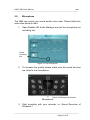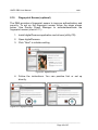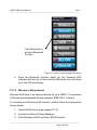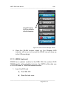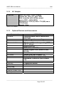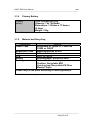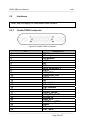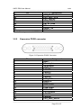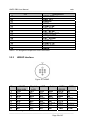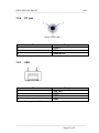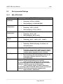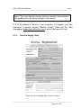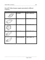
1
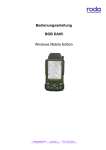
User Manual UMPC DB6 UMPC DB6 User Manual roda ————————————————————————— ————————————————————————— Page 2 of 87 UMPC DB6 User Manual roda ————————————————————————— roda computer GmbH Landstrasse 6 77839 Lichtenau/Baden Telefon: +49(0)7227/9579-0 Telefax: +49(0)7227/9579-20 roda Service Center Hüllhorst Bredenhop 20 32609 Hüllhorst Telefon: +49(0)5744/944-470 Telefax: +49(0)5744/944-475 ————————————————————————— Page 3 of 87 UMPC DB6 User Manual roda ————————————————————————— No part of this publication may be reproduced, transmitted, transcribed, stored in a retrieval system, or translated into any language, or computer language, in any form, or by any means, electronic, mechanical, magnetic, optical, chemical, or other, without the prior written permission of the manufacturer. The manufacturer reserves the right to revise this publication and to make changes to the contents hereof without obligation to notify any person of such revision or changes. The manufacturer makes no representations or warranties, either expressed or implied, with respect to the contents hereof and specifically disclaims any warranties as to merchantability or fitness for any particular purpose. Any of the software described in this manual is sold or licensed "as is". Should the programs prove defective following purchase, the buyer (and not the manufacturer, its distributor, or its dealer), assumes the entire cost of all necessary servicing, repair and any incidental or consequential damages resulting from any software defects. Copyright © 2010 roda computer GmbH Lichtenau, December 201012-13 Author: Christian Fessler Version History: Version Description Date Written by 1.0 Created 13.12.10 C. Fessler 1.1 Keypad Update 19.09.11 C. Fessler ————————————————————————— Page 4 of 87 UMPC DB6 User Manual roda ————————————————————————— Trademark Acknowledgments All product and company names are trademarks or registered trademarks of their respective holders. ————————————————————————— Page 5 of 87 UMPC DB6 User Manual roda ————————————————————————— Conventions This manual is divided into individual chapter with interdependent contents. If you have experience with the use of computers, you may skip individual chapters or directly look up the respective keywords. Pictures and tables are numbered consecutively. Keys and key combinations are written in square brackets, e.g., [Ctrl]+[Alt]+[F1] means that you must press Control, Alt and F1 keys simultaneously. Note Notes contain important information in connection with the directly related text or chapter. Attention You will find Attention notes where data loss or notebook damage may be the result of non-compliance with this note. Warning Warnings inform you that personal damage or damage to the notebook or individual components thereof may be the consequence or carelessness or non-compliance with the respective warning. ————————————————————————— Page 6 of 87 UMPC DB6 User Manual roda ————————————————————————— EMC and Safety Notice Federal Communications Commission Statement This standard equipment has been tested and found to comply with the limits for a class B digital device, pursuant to part 15 of the FCC Rules. These limits are designed to provide reasonable protection against harmful interference in a residential installation. This equipment generates, uses and can radiate radio frequency energy and, if not installed and used in accordance with the instructions, may cause harmful interference to radio communications. However, there is no guarantee that interference will not occur in a particular installation. If this equipment does cause harmful interference to radio or television reception, which can be determined by turning the equipment off and on, the user is encouraged to try to correct the interference by one or more of the following measures: Reorient or relocate the receiving antenna. Increase the separation between the equipment and receiver. Connect the equipment into an outlet on a circuit different from that to which the receiver is connected. Consult the dealer or an experienced radio/TV technician for help. This device complies with Part 15 of the FCC Rules. Operation is subject to the following two conditions: This device may not cause harmful interference This device must accept any interference received, including interference that may cause undesired operation. FCC Caution To assure continued compliance, any changes or modifications not expressly approved by the party responsible for compliance could void the user’s authority to operate this equipment. (Example – use only shielded interface cables when connecting to computer or peripheral devices). ————————————————————————— Page 7 of 87 UMPC DB6 User Manual roda ————————————————————————— Regulatory Information / Disclaimers Installation and use of this UMPC DB6 must be in strict accordance with the instructions included in the user documentation provided with the product. Any changes or modifications (including the antennas) made to this device that are not expressly approved by the manufacturer may void the user’s authority to operate the equipment. The manufacturer is not responsible for any radio or television interference caused by unauthorized modification of this device, or the substitution of the connecting cables and equipment other than manufacturer specified. It is the responsibility of the user to correct any interference caused by such unauthorized modification, substitution or attachment. Manufacturer and its authorized resellers or distributors will assume no liability for any damage or violation of government regulations arising from failing to comply with these guidelines. IMPORTANT NOTE (CO-LOCATION) FCC RF Radiation Exposure Statement: This equipment complies with FCC RF radiation exposure limits set forth for an uncontrolled environment. This device and its antenna must not be co-located or operating in conjunction with any other antenna or transmitter. Note: Descriptions made in this manual are done for standard UMPC DB6. Depending on costumers configuration your device may vary. ————————————————————————— Page 8 of 87 UMPC DB6 User Manual roda ————————————————————————— CE Products with the CE Marking comply with both the EMC Directive (2004/108/EC) and the Low Voltage Directive (2006/95/EC) issued by the Commission of the European Community. Compliance with these directives implies conformity to the following European Norms: EN 55022 ( CISPR 22 ) Radio Frequency Interference EN 55024 ( EN61000-4-2, EN61000-4-3, EN61000-4-4, EN61000-45, EN61000-4-6,EN61000-4-8,EN61000-4-11,EN61000-3-2, EN61000-3-3) Generic Immunity Standard LVD EN 60950 ( IEC950 ) Product Safety, IEC 60950-1:2005 802.11a/b/g/n Restrictions: European standards dictate maximum radiated transmit power of 100mW EIRP and frequency range 2.400-2.4835GHz. In France, the equipment must be restricted to the 2.4465-2.4835GHz frequency range and must be restricted to indoor use. CE Declaration of Conformity Is herewith confirmed to comply with the requirements set out in the Council Directive on the Approximation of the Laws of the Member States relating to Electromagnetic Compatibility (2004/108/EC), Lowvoltage Directive (2006/95/EC) and the procedures given in European Council Directive 99/5/EC. The equipment was passed. The equipment test was performed according to the following European standards. EN 300 328 V.1.7.1:2006 EN 301 893 V.1.4.1 (2007-07) EN 301 V1.8.1 2008-04 / EN 301 489-17 V1.3.2 2008-04 EN 50371:2002 EN 60950-1:2005 ————————————————————————— Page 9 of 87 UMPC DB6 User Manual roda ————————————————————————— UL, TÜV AC Adapter (TÜV includes EN60950 LVD) Power Conservation This computer consumes less power than conventional computers; however, power consumption can be further reduced by properly configuring the Power Management Setups. It is recommended that the power saving functions be enabled even not running on battery power. Please read the power saving features and the setting procedures described in this manual for setting your computer. Recycling All materials used in the construction of this unit are recyclable or environmentally friendly. Please recycle the packing materials, and at the end of the computer's life, all other materials in accordance with the local regulations. Please refer “Material and Recycling” for the contents of the materials. Note: The equipment may still contain tiny amount of hazardous substances for health and environment, though those are below control level. To avoid spreading such substances into the eco system, and to minimize the pressure on the environment, you are encouraged to use the appropriate take-back for reusing or recycling most of the materials in a safe way after the service life. The crossed bin symbol indicates proper disposal is required. For more information on collection, reuse and recycling, please consult the local or regional waste administration for more information. ————————————————————————— Page 10 of 87 UMPC DB6 User Manual roda ————————————————————————— Table of contents 1 1.1 1.2 1.2.1 1.2.2 1.2.3 1.2.4 1.2.5 1.2.6 1.3 1.4 1.5 1.6 Getting Started..................................................................... 14 Introduction .......................................................................... 15 View ..................................................................................... 16 Front View............................................................................ 16 Rear View ............................................................................ 17 Left-Side View (Side C) ....................................................... 17 Right-Side View (Side D) ..................................................... 18 Top View (Side A) ................................................................ 18 Bottom View (Side B) .......................................................... 19 Preparing the UMPC DB6 ................................................... 20 Power-On Self Test (POST) ................................................ 23 Installing the Windows Operating System ........................... 24 Adjusting screen brightness ................................................ 24 2 2.1 2.2 2.3 2.4 2.4.1 2.4.2 2.5 2.6 2.6.1 2.6.2 2.7 2.8 2.9 2.10 2.11 2.11.1 2.11.2 2.11.3 2.11.4 2.11.5 Components and Operation ................................................ 26 Location ............................................................................... 26 Ruggedness......................................................................... 26 Operating Systems .............................................................. 27 Power supply for the UMPC DB6 ........................................ 27 AC Adapter .......................................................................... 27 Battery Operation................................................................. 28 Shutdown ............................................................................. 35 Using Indicators and Keypad............................................... 36 Indicators ............................................................................. 36 Keypad Hotkeys................................................................... 37 Application Menu ................................................................. 38 Touch Screen ...................................................................... 39 Microphone .......................................................................... 41 Fingerprint Sensor (optional) ............................................... 42 Wireless Devices ................................................................. 43 Bluetooth.............................................................................. 43 Wireless LAN (optional) ....................................................... 44 WWAN (optional) ................................................................. 45 GPS (optional) ..................................................................... 47 Camera (optional) ................................................................ 48 3 3.1 3.1.1 Specifications....................................................................... 51 Components ........................................................................ 51 System Unit ......................................................................... 51 ————————————————————————— Page 11 of 87 UMPC DB6 User Manual roda ————————————————————————— 3.1.2 3.1.3 3.1.4 3.1.5 3.2 3.2.1 3.2.2 3.2.3 3.2.4 3.2.5 3.3 3.3.1 3.3.2 3.3.3 AC Adapter .......................................................................... 52 Optional Devices and Accessories ...................................... 52 Primary Battery .................................................................... 53 Material and Recycling ........................................................ 53 Interfaces ............................................................................. 54 Cradle POGO connector ..................................................... 54 Expansion POGO connector ............................................... 55 HRS8P Interface.................................................................. 56 DC jack ................................................................................ 57 USB ..................................................................................... 57 Environmental Ratings ........................................................ 58 MIL-STD-810G .................................................................... 58 IEC IP .................................................................................. 59 MIL-STD-461F (optional) ..................................................... 60 4 4.1 4.2 4.3 4.4 4.5 BIOS Setup .......................................................................... 62 Main Menu ........................................................................... 62 Advanced Menu................................................................... 63 Boot Menu ........................................................................... 63 Security Menu...................................................................... 64 Exit Menu ............................................................................. 64 5 5.1 5.1.1 5.1.2 5.1.3 5.1.4 5.1.5 5.1.6 5.1.7 5.1.8 5.1.9 5.1.10 5.1.11 5.1.12 5.2 5.2.1 Drivers and Utilities.............................................................. 66 Driver ................................................................................... 66 Chipset (XP only)................................................................. 66 Graphic Controller ............................................................... 67 Resolution ............................................................................ 67 Touch Screen ...................................................................... 67 Stickpointer .......................................................................... 67 Audio ................................................................................... 68 Fingerprint Sensor (optional) ............................................... 68 Bluetooth ............................................................................. 68 WLAN (optional) .................................................................. 68 WWAN (optional) ................................................................. 69 GPS (optional) ..................................................................... 69 Gigabit LAN (optional) ......................................................... 69 Utilities ................................................................................. 70 Device Power Manager ....................................................... 70 6 6.1 Maintenance and Service .................................................... 72 Cleaning .............................................................................. 72 ————————————————————————— Page 12 of 87 UMPC DB6 User Manual roda ————————————————————————— 6.2 6.3 6.3.1 6.3.2 Troubleshooting ................................................................... 72 Service ................................................................................. 72 Service Supply Note ............................................................ 73 Downloads ........................................................................... 74 Annex ............................................................................................. 76 Annex A: List of abbreviations .......................................................... 76 Annex B: Table of power supply connectors for different countries . 78 Annex C: List of figures..................................................................... 79 Annex D: List of tables ...................................................................... 80 Annex E: Material Safety Data Sheet Battery .................................. 81 ————————————————————————— Page 13 of 87 UMPC DB6 User Manual roda ————————————————————————— Getting Started 1 Getting Started ————————————————————————— Page 14 of 87 UMPC DB6 User Manual roda ————————————————————————— 1.1 Introduction The Ultra Mobile PC DB6 allows operation under extreme environmental conditions. All interfaces and slots are covered. The casing is equipped with rubber bumpers and provides a maximum of protection against shock, vibration, dust and humidity. The technical details are listed in chapter 3 Specifications. The following lists the standard scope of delivery for the UMPC. Please use this list to check the package contents for completeness. Contact dealer if one or more of the following listed items are not contained in the package. UMPC DB6 AC Adapter AC Power cord (not pictured) Utility CD Battery (may be installed) Stylus Pen (2x) Quick Guide Figure 1: UMPC DB6 scope of delivery ————————————————————————— Page 15 of 87 UMPC DB6 User Manual roda ————————————————————————— 1.2 View 1.2.1 Front View Figure 2: Front view and keypad 1. Embedded Antennas: Embedded antennas for wireless application 2. LCD: Displaying the visual output of DB6 3. LED Indicators: Indicating status by different colours and lighting methods 4. Keypad: For quick operation Figure 3: Front overview ————————————————————————— Page 16 of 87 UMPC DB6 User Manual roda ————————————————————————— 1.2.2 Rear View 1 1. Finger Print Scanner (optional) 2M AF Camera (optional) Speaker Stylus Pen Battery Lock Battery 2. 3. 4. 5. 6. 2 3 5 4 6 Figure 4: Rear side overview 1.2.3 Left-Side View (Side C) Figure 5: Left-side view 1 1. Cradle POGO Connector ————————————————————————— Page 17 of 87 UMPC DB6 User Manual roda ————————————————————————— 1.2.4 Right-Side View (Side D) Figure 6: Right-side view 1 2 3 1. SIM Card Slot 2. USB 2.0 Port (Host) 3. SD Card Slot 1.2.5 Top View (Side A) 1 Figure 7: Top view 2 1. Option 1 2. Option 2 Options (Select 2 out of 7): a) Sealed USB b) Bluetooth SMA Antenna c) Sealed Audio d) GPS SMA Antenna e) WI-FI SMA Antenna f) HSDPA Antenna g) Sealed Gigabit LAN (Trade Off: WLAN) ————————————————————————— Page 18 of 87 UMPC DB6 User Manual roda ————————————————————————— 1.2.6 Bottom View (Side B) 1 2 Figure 8: Bottom view 1. DC power jack 2. Option 3 Options: Expansion POGO Connector Signals consisted: a) USB 2.0 1x b) COM1 (RS232) c) Gigabit LAN d) DC In e) RGB (Trade Off: Cradle RGB) ————————————————————————— Page 19 of 87 UMPC DB6 User Manual roda ————————————————————————— 1.3 Preparing the UMPC DB6 Insert the battery module into the battery module slot and tighten the safety screw. Note: Please use a coin to turn the screw. Using screwdrivers might damage the screw or case. Figure 9: Mounting the battery Connect the line cable with the power supply unit and plug the plug into the electrical outlet. Figure 10: Connecting AC/DC Adapter ————————————————————————— Page 20 of 87 UMPC DB6 User Manual roda ————————————————————————— Note: The enclosed line cable complies with the specifications of the country in which the UMPC was purchased. Please ensure that the line cable has been approved for the country in which the notebook will be used. Find further information on countryspecific power plug version in the Annex. Plug the DC plug of the power supply unit into the DC input of the DB6 and lock the connector well clockwise. Charge the DB6 for at least 10 minutes. Note: There is no memory effect with the used Lithium-Ion batteries. It is not necessary to discharge the battery completely. Turn the UMPC DB6 on by pressing the power button. . Figure 11: Power Button Note: The power is able to be ON without any battery mounted once all power cords are connected. Turn OFF the computer using either one of the following procedures: o Press power button for 4 seconds to have a “Hard” power off. ————————————————————————— Page 21 of 87 UMPC DB6 User Manual roda ————————————————————————— System shuts down without saving any data or parameters o Press power button momentarily to “Standby” or “Hibernate” dependent on operating system (OS) and power scheme settings. Note: Some operating systems may not support these functions. o If you are using Microsoft Windows operating system click Start Shutdown or press the Windows button to turn the computer off. Driver or application software installation may be necessary for further operation. ————————————————————————— Page 22 of 87 UMPC DB6 User Manual roda ————————————————————————— 1.4 Power-On Self Test (POST) Figure 12: POST screen Note: It is recommended to use an external USB keyboard to set up BIOS. See chapter 4 BIOS Setup. After start press [DEL] to start the BIOS setup of the UMPC DB6. Check chapter BIOS Setup for further information. The system will now run a Power-On Self Test (POST). During this test the main UMPC components are checked: processor memory interrupt controller inputs and outputs DMA controller, clock unit and video controller As part of this self test, the current hardware configuration is compared with the system’s configuration data stored in the batterybased CMOS-RAM. In addition, all hardware components are routinely checked. If during the Power-On Self Test a deviation from the current configuration and/or a hardware error is detected, the ————————————————————————— Page 23 of 87 UMPC DB6 User Manual roda ————————————————————————— UMPC will automatically display a message requesting to start the Setup service program (see chapter 4 BIOS Setup). 1.5 Installing the Windows Operating System When you switch on the UMPC DB6 for the first time, the Microsoft Windows 7 start screen will appear. Follow the instructions on the screen. When switching on the computer for the first time, the enclosed software will be installed and configured. Since this process may not be interrupted, you should allow some time for it and should leave the UMPC connected to the line voltage via the AC adapter. During installation, you may only reboot the UMPC DB6 when requested to do so. Note: Only applies, if an installed Windows 7 was part of delivery. 1.6 Adjusting screen brightness You can adjust LCD brightness to your needs with the following keys: Increase brightness: Fn + Volume up Reduce brightness: Fn + Volume down ————————————————————————— Page 24 of 87 UMPC DB6 User Manual roda ————————————————————————— Components and Operations ————————————————————————— Page 25 of 87 UMPC DB6 User Manual roda ————————————————————————— 2 Components and Operation 2.1 Location A clean and moisture-free environment is preferred. Make room for air circulation. Avoid areas with: Sudden or extreme changes in temperature. Extreme heat. Strong electromagnetic fields (near television set, motor rotation area, etc.). Dust or high humidity. If it is necessary to work in a hostile environment, please regularly maintain your computer by cleaning dust, water, etc. to keep it in optimal condition. 2.2 Ruggedness The computer is designed with rugged features as vibration, shock, dust, and rain/water protection. However, it is still necessary to provide appropriate protection while operating in harsh environments. NEVER immerse the computer completely in water. Doing so may cause permanent damages. Drop may cause parts break or permanent damages. The I/O ports and devices must have caps tightly closed or cable inlets sealed while exposed to water or dust. All connectors will corrode if exposed to water or moisture. Corrosion is accelerated if the power is ON. Please take proper measures in cable connection to avoid water entering into connectors. The DC jack and cables are sealed and may be operated with water splashing while attached. All port covers should be in place when no cable is attached. ————————————————————————— Page 26 of 87 UMPC DB6 User Manual roda ————————————————————————— 2.3 Operating Systems The computer is compatible with most operating systems (OS). However, not all functions are 100% compatible. For example, ACPI, APM, Smart Battery, etc. are not available on DOS, Windows NT, and other non-Microsoft OS. Consequently “Standby”, “Hibernation”, “Battery Gauge”, etc. would not work under such operating systems. Note: ACPI: Advanced Configurations and Power Interface APM: Advanced Power Management 2.4 Power supply for the UMPC DB6 The DB6 may be power supplied either via the AC adapter or the integrated battery. 2.4.1 AC Adapter Figure 13: AC adapter The enclosed AC adapter automatically adjusts to the line voltage of the respective country. Make sure you have the correct countryspecific power-plug version (see Annex B). ————————————————————————— Page 27 of 87 UMPC DB6 User Manual roda ————————————————————————— The AC adapter supplies the connected UMPC with power and charges the integrated Lithium-Ion battery. The green operation LED illuminates as soon as the adapter is connected with the power line, regardless whether the adapter is connected with the DB6. For power supply to the UMPC DB6, only use original manufacturer parts provided for this PC. Otherwise you may cause damage to the notebook and/or externally connected peripherals. Moreover, the manufacturer’s warranty will forfeit if you ignore these instructions 2.4.2 Battery Operation The exchangeable Lithium-Ion battery is the DB6 main power source when the AC adapter is not connected. As a standard, the UMPC DB6 is equipped both with a primary and a real-time clock (RTC) battery. Figure 14: Battery ————————————————————————— Page 28 of 87 UMPC DB6 User Manual roda ————————————————————————— RTC-Battery The RTC (Real Time Clock) battery provides power to the integrated real-time clock and the calendar even when the notebook is switched off and not connected with the AC adapter. In addition, the RTC battery is responsible for maintaining the system settings in BIOS. The RTC battery is also charged via the connected AC adapter. In order to avoid losing system settings when the UMPC is not used for a longer period of time, you should connect the DB6 with the AC adapter for a few hours a least once a month. When commissioning the UMPC, please make sure that date and time settings are correct; otherwise, you will need to adjust them. Note: If required, the RTC battery installed in the UMPC should only be replaced by authorised service staff, since it requires opening the UMPC. Primary Battery Before the battery is operated for the first time, the battery should be fully charged. Charging the Battery An AC adapter, an AC power cord and a battery are required during battery charging. These are standard accessories for your handheld computer. Do always use the AC adapter, the AC power cord and the battery designed for your computer. After unpacking your UMPC, you need to start charging the battery for further use. Please connect your AC power cord and AC adapter well with the plug and mount your battery well before starting charging (see 1.3). We suggest you to charge the battery for about 8hours at the very beginning to give a full charge for your battery. When the battery is nearly exhausted, please save and close the files you are currently working on and plug in the AC adapter to recharge the battery or swap with a charged battery. ————————————————————————— Page 29 of 87 UMPC DB6 User Manual roda ————————————————————————— Monitoring Battery Capacity If the DB6 operates with the battery, you may monitor the remaining battery energy as follows in the Windows operation system: Click on “Battery” symbol in the task bar, or in Windows system control, on the “Energy” symbol. The following window will inform you on the charge status of the integrated battery/batteries. Figure 15: Energy options (German) Battery – Warnings When the battery is nearly exhausted, the OS will show a warning icon. Also, the Power Indicator LED will flash green when the battery level is under 15%. ————————————————————————— Page 30 of 87 UMPC DB6 User Manual roda ————————————————————————— Note: The following information refers to the standard settings in the Windows XP operating system. If another operating system is installed, the energy settings may not function properly. This particular applies to Windows NT and operating systems which are not Windows based. Warning with low Battery-Charge State If the remaining battery power drops under 10% of the overall capacity, the UMPC will inform you about this situation as follows in the standard settings: A one-time signal will sound A text will be displayed that warns you of low battery-charge state The UMPC will remain switched on. As this time, you should immediately store your work, since battery power will last for another 5 to 10 minutes only. Warning with critical Battery-Charge State If the remaining battery power has reached a rest capacity of 5%, the DB6 will automatically carry out the following measures in the standard settings: A one-time signal will sound A text will be displayed that warns you of critical batterycharge state The UMPC will switch to idle state If you have not done so, you must now connect the UMPC with the AC adapter or replace the low battery with a fully charged one. If you switch on the UMPC DB6 after the automatic shutdown, note, that the battery will allow operation for a very short time. During the last minutes of battery power, the battery-charge state indicator will indicate this critical state. ————————————————————————— Page 31 of 87 UMPC DB6 User Manual roda ————————————————————————— Note: Battery performance and lifecycle depend on a number of factors, such as ambient temperature, age, number of charge and discharge cycles, etc. Replacing Battery When the battery is nearly exhausted, there are two ways to keep your handheld computer working. Connect the AC adapter and the power cord designed for this handheld computer to start charging is one method; directly replace a charged batter designed for this handheld computer may be the other one. Note: Always remember to turn OFF the power before replacing the battery. You can change the battery in 30 seconds under standby mode; otherwise it may cause data loss or malfunction of your handheld computer. Power Saving Tips Turn OFF the LCD backlight when not using the UMPC Lower the intensity of the LCD backlight Use well with Shutdown, Standby and Hibernation Use well with the power management settings in your OS Supporting ACPI Your UMPC supports ACPI for power management. With ACPI and an ACPI-compliant operating system such as Windows, this feature will allow you to reduce the power consumption for energy saving. LED indicators will show the actual ACPI state: Standby: Power LED indicator is ON, other LED indicators are OFF Hibernate: All LED indicators are OFF Shutdown: All LED indicators are OFF ————————————————————————— Page 32 of 87 UMPC DB6 User Manual roda ————————————————————————— AC Adapter and AC Power Cord Safety There are specific power requirements for your UMPC: Only use an approved AC adapter designed for this computer. Use a grounded power outlet. When unplugging the AC power cord, please be sure to disconnect it from the plug head but from its wire. Make sure the socket and any other extension cords you use can support the total current load of all the connected devices. Before cleaning the computer, make sure it is disconnected from any external power supply. Battery Precautions Only use the batteries designed for this computer. The wrong battery may cause explosion, leakage or damage to the computer. Do not remove the battery from the UMPC while it is powered on. Do not continuously use a battery which has been dropped or which appears damaged (e.g. bent or twisted) in any way. Even if the computer is able to work with a damaged battery, circuit damage may occur and possibly cause fire. Always use the charger designed for this UMPC to recharge the battery. Incorrect recharging may damage the battery. Do not try to repair a battery by yourself. Refer to any battery repair or replacement, please contact with your service representative. Please dispose of a damaged battery promptly and carefully. Explosion or leakage may occur if the battery is exposed to fire, improperly handled or discarded. ————————————————————————— Page 33 of 87 UMPC DB6 User Manual roda ————————————————————————— Warning Before any upgrade procedures, make sure the power is turned OFF and all cables are disconnected (including telephone lines). Also, it is advisable to remove your battery to prevent turning the computer on accidentally. Battery Disposal and Caution The product you have purchased contains a rechargeable battery. The battery is recyclable. At the end of its service life, under various state and local laws, it may be illegal to dispose of this battery into the municipal waste stream. Check with your local solid waste officials for details in your area for recycling options or proper disposal. Danger of explosion may possibly occur if the battery is replaced incorrectly. Replace only with the same or equivalent battery recommended by the manufacturer. Discard the used battery according to the manufacturer’s instructions. Using the Energy-Saving Mode If you operate the DB6 with a battery, you may choose to use different energy-saving functions in order to extend operation time. Among other things, the duration of the battery depends on the following factors: Processor type and CPU clock frequency Screen brightness LCD switch-off Frequency and duration of access to the hard disk and optical drives Initial battery-charge status Usage intensity of connected and inserted additional devices, such as USB devices or Express cards that are powered via the battery ————————————————————————— Page 34 of 87 UMPC DB6 User Manual roda ————————————————————————— Setting the Energy-Saving Functions Windows 7 Under Start System control Performance and maintenance Energy options, you can set the DB6’s energy-saving functions. Standby Mode If you wish to briefly interrupt your work, you may switch off the UMPC without closing the application. In standby mode, the LCD is switched off, the hard disk drive shuts down and the processor is clocked to a very low frequency. The DB6’s RAM continues to be supplied with energy so that all the information remains in the RAM. When you turn the notebook back on, you can continue your work where you left off. Hibernate When hibernate is activated, all data in the DB6’s RAM and the information on the screen are stored on the hard disk drive. Thereafter, the UMPC shuts down. Depending on the open programs, this process may take a few seconds. Note: Activating standby mode will save energy, when you switch the notebook on and off frequently. If you do not use the UMPC for a long period of time, end the energy-saving mode and switch off the notebook. 2.5 Shutdown The following procedure is recommended in shutting down the computer: Save any work you want to keep ————————————————————————— Page 35 of 87 UMPC DB6 User Manual roda ————————————————————————— Make sure none of the disk drives are active (HDD, FDD, CD-ROM, DVD) Remove any diskettes, CD-ROMs, or other media Follow the shut down procedure of you operating system Failure to shut down the computer properly may result in loss of data or hardware damages. Automatic shut down is activated at battery exhaust. Be sure to finish your work and save all your data when the battery low warning appears. 2.6 Using Indicators and Keypad Your UMPC is designed with a keypad for easy and quick operation. LED indicators are showing the state of your UMPC. 2.6.1 Indicators Figure 16: LED indicators Power Indicator Green: Power Flashing red: Standby (S3) Consistent Green + Flashing Red: Battery power is lower than 15% during Standby Charger Indicator Orange: Charging battery ————————————————————————— Page 36 of 87 UMPC DB6 User Manual roda ————————————————————————— SSD Indicator Green: SSD access (read/write) Red: Input lock Wireless Device Indicator 2.6.2 Blue: Wireless Device active Keypad Hotkeys Figure 17: Keypad Note: Please install the Device Power Manager application to activate the hotkeys. ————————————————————————— Page 37 of 87 UMPC DB6 User Manual roda ————————————————————————— 1st Layer: 1. 2. 3. 4. 5. 6. 7. 8. 9. 10. 11. 12. 2.7 2nd Layer: Windowskey + U Application Menu Power ON/OFF Volume up Volume down Mouse left button Invisible mode ON/OFF Camera Mouse right button Screen rotation Login Function key a. Fn + Invisible mode ON/OFF = Keypad backlight ON/OFF b. Fn + Volume up/down = LCD brightness up/down c. Fn + Key 1 = Input lock d. Fn + Application Menu = Enter Application Menu Often used functions can be accessed with the help of the Application Menu hotkey. The Device Power Manager includes the driver of the keypad hotkeys. Install this application before activating the keypad hotkeys. Device Power Manager My Documents Camera Application Control Panel Internet Explorer Keyboard Media Player Mouse left button Notepad Standby Figure 18: Application Menu functions ————————————————————————— Page 38 of 87 UMPC DB6 User Manual roda ————————————————————————— 2.8 Touch Screen The DB6 is equipped with a high sensitive touch panel allowing you to navigate on the touch screen easily without using any other devices such as external keyboard or mouse. Before using touch screen, please follow the illustrations below to calibrate the touch screen. 1. Open PenMount Control Panel 2. Click “Configure” to start Figure 19: Configure 3. Click “Standard Calibration” and follow the instructions ————————————————————————— Page 39 of 87 UMPC DB6 User Manual roda ————————————————————————— Figure 20: Standard Calibration The DB6 is equipped with a stylus pen to use the touch screen. Touch screen usage: Single Click: Double Click: Drag and Drop: Right Click: Tap the touch screen with the stylus pen gently. Tap the touch screen quickly twice with the stylus pen. Tap and hold the object with the stylus pen and move to the destination you want (drag). Leave the stylus pen from the touch screen once you finished dragging (drop). Tap and hold for 2~3 seconds. Note: Under direct sunlight for a longer time, the touch screen could heat up over 70°C. ————————————————————————— Page 40 of 87 UMPC DB6 User Manual roda ————————————————————————— 2.9 Microphone The DB6 can record your sound and/or voice input. Please follow the instruction below to start. 1. Open Realtek HD Audio Manager and set the microphone as recording tool. Set as recording tool Figure 21: Set microphone 2. To increase the quality please make sure the sound sources are close to the microphone Figure 22: Microphone location Microphone 3. Start recording with your recorder i.e. Sound Recorder of Windows 7. ————————————————————————— Page 41 of 87 UMPC DB6 User Manual roda ————————————————————————— 2.10 Fingerprint Sensor (optional) The DB6 provides a fingerprint sensor to improve authentication and security. To set up the fingerprint sensor follow the steps shown below. Use Device Power Manager to activate/deactivate the fingerprint sensor (check 2.11). 1. Install digitalPersona application and drivers (utility CD). 2. Open digitalPersona 3. Click “Next” to initialize setting Figure 23: digitalPersona 4. Follow the instructions. You can practice first or set up directly. Figure 24: Fingerprint setup ————————————————————————— Page 42 of 87 UMPC DB6 User Manual roda ————————————————————————— 2.11 Wireless Devices Note: You can turn wireless devices ON/OFF with the help of the Device Power Manager application. You must install the “Device Power Manager” in order to use the wireless devices. To install the “Device Power Manager” application run “Utilities\Device Power Manager\DB6 Utility 20101122(1.0.0.6)\setup.exe” (name may change with new versions) and follow the instructions to install. 2.11.1 Bluetooth Bluetooth is a standard wireless device along with your UMPC. A Class 2 Bluetooth® v2.1 + EDR system is backward compatible with v1.1/1.2/2.0 devices. It supports a short range wireless communication to connect with other Bluetooth devices. To activate the Bluetooth function, please follow the illustrations below: 1. Install the Bluetooth driver (see chapter 5.1.8) 2. Launch the Device Power Manager 3. Click Bluetooth to activate Bluetooth function ————————————————————————— Page 43 of 87 UMPC DB6 User Manual roda ————————————————————————— Click Bluetooth to activate Bluetooth function Figure 25: Device Power Manager Bluetooth 4. Once the Bluetooth function starts up, the Wireless LED indicator will turn on in blue and the Bluetooth icon will show up in the OS accordingly. 2.11.2 Wireless LAN (optional) Wireless LAN card is an optional device for your UMPC. The wireless LAN card and embedded antenna support IEEE 802.11 a/b/g/n. To activate your Wireless LAN function, please follow the illustrations shown below. 1. Install WLAN driver (see chapter 5.1.9) 2. Launch the Device Power Manager 3. Click Wireless LAN to activate WLAN function ————————————————————————— Page 44 of 87 UMPC DB6 User Manual roda ————————————————————————— Click Wireless LAN to activate WLAN function Figure 26: Device Power Manager WLAN 4. Once the WLAN function starts up, the Wireless LED indicator will turn on in blue and the WLAN icon will show up in the OS accordingly. 2.11.3 WWAN (optional) WWAN is an optional module for the DB6. With the optional 3.5G WWAN module with embedded antenna, the UMPC will be able use a 3.5G SIM card for WWAN telecommunication. 1. Insert the SIM card a) Turn DB6 OFF b) Open the lock cover ————————————————————————— Page 45 of 87 UMPC DB6 User Manual roda ————————————————————————— c) Pull up the lock cover d) Put the SIM card into the SIM card slot e) Lock the cover 2. Install WWAN driver (see chapter 5.1.10) 3. Launch the Device Power Manager 4. Click WWAN to activate WWAN function ————————————————————————— Page 46 of 87 UMPC DB6 User Manual roda ————————————————————————— Click WWAN to activate WWAN function Figure 27: Device Power Manager WWAN 5. Once the WWAN function starts up, the Wireless LED indicator will turn on in blue. 2.11.4 GPS (optional) GPS is an optional module for the DB6. This GPS module supports GPS and Galileo systems. 1. Install GPS drivers (see chapter 5.1.11) and application 2. Launch the Device Power Manager 3. Click GPS to activate GPS function ————————————————————————— Page 47 of 87 UMPC DB6 User Manual roda ————————————————————————— Click GPS to activate GPS function Figure 28: Device Power Manager GPS 2.11.5 Camera (optional) The DB6 provides an optional 2 million-pixel CMOS camera to capture images at any time. Also, it supports video recording function. Press the camera button or the application menu button to enter the camera application main window. Figure 29: Camera main window ————————————————————————— Page 48 of 87 UMPC DB6 User Manual roda ————————————————————————— Taking pictures Click in the camera window or press the camera button again to take pictures. Pictures will automatically be saved in C:\Documents and Settings\User Name\My Documents\My Pictures. Recording videos Click in the camera window to record videos. To stop recording . Adjusting volume during recording is possible. click Videos will be saved in C:\Documents and Settings\User Name\My Video. Other functions Video Format Properties: Advanced video format settings Image Properties: Advanced image settings and camera control Volume Level: Adjust video recording volume Flash LED Settings: Advanced flash LED settings Exit: Exit the camera window/function Note: Rotating the screen vertically while using the camera is recommended. ————————————————————————— Page 49 of 87 UMPC DB6 User Manual roda ————————————————————————— Specifications ————————————————————————— Page 50 of 87 UMPC DB6 User Manual roda ————————————————————————— 3 Specifications 3.1 Components 3.1.1 System Unit Component CPU Level 2 Cache Video Memory Chipset RAM VGA Graphic Controller Touch Screen HDD Sound Communication Interfaces (side D) Interfaces (side C) Interfaces (side B) Interfaces (side A) Primary battery Power input Dimensions Weight Case Colour Certification TM UMPC DB6 Processor Z530 1.6GHz Intel® Atom 512KB Max. 509MB (shared Memory) Intel® SCH US15W 2GB DDR2 533MHz 5“ WVGA (800x480 Pixel) sunlight-readable, LED backlight Intel® GMA 500, supporting Microsoft® DirectX9 and Open GL 1.1 Rugged Touch Screen 1.8” PATA SSD HD Audio Codec and Amplifier with Mono Speaker Bluetooth® V2.1 + EDR (Class 2) USB 2.0 1x SD Card Slot 1x SIM Card Slot 1x Cradle POGO Connector DC Power Jack, Option Option 2x 7.4V/3900mAH Lithium-Ion Battery DC 12V ~ 32V 200 (L) mm x 94 (W) mm x 36 (H) mm 690 g (depends on configuration) Magnesium Alloy black/NATO green CE, FCC, WEEE, REACH, MIL-STD810G, IP55 (DB6-I)/IP65 (DB6-M), MILSTD-461F (DB6-M standard, DB6-I option) Table 1: UMPC components ————————————————————————— Page 51 of 87 UMPC DB6 User Manual roda ————————————————————————— 3.1.2 AC Adapter Features Input: AC 100V ~ 240V 50/60Hz Output: DC 12V ± 1V, max. 36W Also complies with military power source100V ~ 240V 400Hz Dimensions: 116.8 (L) mm x 77.8 (W) mm x 12.5 (H) mm Weight: 185g Table 2: AC adapter 3.1.3 Optional Devices and Accessories Component Camera UMPC DB6 2 Million-pixels CMOS camera with flashlight Supporting video recording Communication Wireless LAN card: supporting IEEE 802.11 a/b/g/n WWAN:HSDPA GPS: Ublox LEA-5H Sealed Gigabit LAN (trade off with WLAN) I/O Ports Sealed USB (see chapter 1.2) Sealed Audio (see chapter 1.2) Expansion Connector (see chapter 1.2) Security Fingerprint Reader Carry Bag Vehicle Power Cord Table 3: Possible options ————————————————————————— Page 52 of 87 UMPC DB6 User Manual roda ————————————————————————— 3.1.4 Primary Battery Primary battery Type: Lithium-Ion cells Capacity: 7.4V 3900mAh Dimensions: 116.8mm x 77.8mm x 12.5mm Weight: 185g Table 4: Battery 3.1.5 Material and Recycling Component Plastic Case Material Recyclable UL grade PC + ABS GE C2800 or C6200 Magnesium Case Magnesium alloy AZ91D Keypad Silicon Rubber PCB FR-4, UL 94 V0 Battery Rechargeable Lithium-Ion cells Packing Carton: Unbleached paper Cushion: Recyclable EPE Carrying bag: Recyclable PE Fibre Manual: Paper Please recycle the parts according to local regulations. Table 5: Material and recycling ————————————————————————— Page 53 of 87 UMPC DB6 User Manual roda ————————————————————————— 3.2 Interfaces Note: May not apply for customized DB6 models. 3.2.1 Cradle POGO connector Figure 30: Cradle POGO connector Pin 1 2 3 4 5 6 7 8 9 10 11 12 13 14 15 16 17 18 19 20 21 22 23 24 Assignment GND1 VA-adapter VA-adapter +V5S NC NC SCH_GPIOSUS_3 RST# USB_PN5 USBClient_PN2 GND2 NC VA-adapter VA-adapter CRT-GREEN NC Detect_Sense CRT_DDC_DATA RTCRST# USB_PP5 USBCLient_PP2 GND3 NC CRT_RED ————————————————————————— Page 54 of 87 UMPC DB6 User Manual roda ————————————————————————— Pin 25 26 27 28 29 30 31 32 Assignment CRT_BLUE CRT_DDC_CLK CRT_HSYNC CRT_VSYNC PM_S3_ON# NC Detect_OK GND4 Table 6: Pin assignment cradle POGO connector 3.2.2 Expansion POGO connector Figure 31: Expansion POGO Connector Pin 1 2 3 4 5 6 7 8 9 10 11 12 13 14 15 16 17 18 Assignment GND1 VA-adapter VA-adapter +V5S LAN-D1+ LAN-D1LAN-D2+ LAN-D2USB_DM1 USB-D3+ GND2 COM1-DCD COM1-RXD COM-DSR CRT-GREEN LAN-D4+ LAN-D4CRT_DDC_DATA ————————————————————————— Page 55 of 87 UMPC DB6 User Manual roda ————————————————————————— Pin Assignment COM1-RTS USB_DP1 LAN-D3GND3 COM1-TXD CRT_RED CRT_BLUE CRT_DDC_CLK CRT_HSYNC CRT_VSYNC COM1-RI COM1-CTS COM1-DTR GND4 19 20 21 22 23 24 25 26 27 28 29 30 31 32 Table 7: Pin assignment expansion POGO connector 3.2.3 HRS8P Interface Figure 32: HRS8P Pin 1 2 3 4 5 6 7 8 10/100 Mbit LAN TX+ TXRX+ NC RXNC NC NC Gigabit LAN TX+ TXRX+ D3+ RXD3D4+ D4- USB Audio D1+ D1NC GND NC GND 5V 5V H-R H-L MIC DET NC AGND NC NC COM RS232 DCD RXD DSR RI CTS RTS DTR TXD RGB R G B GND H-SYNC V-SYNC DATA CLK Table 8: Pin assignment HRS8P ————————————————————————— Page 56 of 87 UMPC DB6 User Manual roda ————————————————————————— 3.2.4 DC jack Figure 33: DC jack Pin 1 2 3 Assignment DCIn + NC GND/DCIn- Table 9: Pin assignment DC jack 3.2.5 USB Figure 34: USB Pin 1 2 3 4 Assignment Vcc +5V USBUSB+ GND Table 10: Pin assignment USB ————————————————————————— Page 57 of 87 UMPC DB6 User Manual roda ————————————————————————— 3.3 Environmental Ratings 3.3.1 MIL-STD-810G Item Low pressure (Altitude) High temperature Low temperature Test Criteria According to MIL-STD-810G, Method 500.5 procedure I, II Operating: 4.572m (15,000ft) Non Operating: 12.192m (40,000ft According to MIL-STD-810G, Method 501.5 procedure I, II Operating: +50°C (+122°F) Non Operating: +70°C (+158°F) According to MIL-STD-810G, Method 502.5 procedure I, II Operating: -20°C (-4°F) Non Operating: -40°C (-40°F) Temperature shock According to MIL-STD-810F, Method 503.5 procedure I-A Rain According to MIL-STD-810G, Method 506.5 procedure II Operating: -20°C ~ +60°C (-4°F ~ +140°F) Operating: 276kPa (40 psig), 5 surfaces, 40 minutes/surface Humidity According to MIL-STD-810G, Method 507.5 Salt Fog Vibration Operating: (Aggravated) 24 hours/cycle, total of 10 cycles Between 30°C (86°F) and 60°C (140°F) with the relative humidity at 95% constant) According to MIL-STD-810G, Method 509.5 Non Operating: Salt concentration of 5+-1%, 24 hours wet + 24hours dry/cycle. Total of 2 cycles/96 hours 1. According to MIL-STD-810G, Method 514.6 procedure 1 category 20 (Ground Vehicles-ground mobile) Table 514.6C-VII, Figure 514.6C-3, 60min/axis 2. According to MIL-STD-810G, Method 514.6 procedure I category 14 (Rotary wing aircraft-Helicopter) Table 514.6C-III, Figure 514.6D-3, 60min/axis 3. According to MIL-STD-810G, Method 514.6 procedure IV category 24 (all material-minimum integrity test) Figure 514.6E-1, 60min/axis ————————————————————————— Page 58 of 87 UMPC DB6 User Manual roda ————————————————————————— Item Test Criteria According to MIL-STD-810G, Method 516.6 procedure I, IV Shock Operating: Figure 516.6-10, Table 516.5C-II, 40g, 11ms, terminal-peak saw tooth shock pulse Non Operating: 122cm onto each face, edge and corner for a total of 26 drops Solar radiation According to MIL-STD-810G, Method 505.5 procedure I Explosive Atmosphere Operating : Figure 505.4-1 A1 According to MIL-STD-810F, Method 511.5 procedure I Operating test Table 11: MIL-STD-810 3.3.2 IEC IP Standards IEC 60529 IP6x Dust-tight IEC 60529 IPx5 Water spray (water jet) Parameters Powder type: Talcum Dust quantity: 2kg Chamber size: 1m³ Test duration: 8h Tube radius: 400mm Water flow: 1.8l/min Number of open holes: 25 Test duration: 10min Table 12: IEC IP Note: With all caps mounted. ————————————————————————— Page 59 of 87 UMPC DB6 User Manual roda ————————————————————————— 3.3.3 MIL-STD-461F (optional) Standards MIL-STD-461F (M-models only) Parameters CE101: Conducted Emissions, Power Leads 30Hz~10kHz CE102: Conducted Emissions, Power Leads, 10KHz~10MHz CS101: Conducted Susceptibility, Power Leads, 30Hz~150KHz Curve #2 CS114: Conducted Susceptibility, Bulk Cable Injection, 10KHz~200MHz CS115: Conducted Susceptibility, Bulk Cable Injection, Impulse Excitation CS116: Conducted Susceptibility, Damper Sinusoidal Transients, Cable and Power Leads, 10KHz~ 100MHz RE101: Radiated Emissions, Magnetic Field, 30Hz~100KHz RE102: Radiated Emissions, Electric Field, 10KHz~18GHz RS101: Radiated Susceptibility, Magnetic Field, 30Hz~100KHz RS103: Radiated Susceptibility, Electric Field, 2MHz~40GHz Table 13: MIL-STD-461F ————————————————————————— Page 60 of 87 UMPC DB6 User Manual roda ————————————————————————— BIOS Setup ————————————————————————— Page 61 of 87 UMPC DB6 User Manual roda ————————————————————————— 4 BIOS Setup Note: The contents configurations. may vary depending on computer Note: You need to connect a USB keyboard with the DB6 to change BIOS settings. Only experienced users should change BIOS settings. Wrong BIOS settings may cause malfunctions. After an USB keyboard is connected with the DB6 press “Del” during POST to enter BIOS. 4.1 Main Menu The Main Menu displays a system overview and the operating instructions. Figure 35: BIOS Main Menu ————————————————————————— Page 62 of 87 UMPC DB6 User Manual roda ————————————————————————— 4.2 Advanced Menu Advanced settings can be done in the Advanced Menu. Figure 36: BIOS Advanced Menu 4.3 Boot Menu Boot sequence can be adjusted in the Boot Menu. Figure 37: BIOS Boot Menu ————————————————————————— Page 63 of 87 UMPC DB6 User Manual roda ————————————————————————— 4.4 Security Menu Set the security settings in the Security Menu. Figure 38: BIOS Security Menu 4.5 Exit Menu Save and exit option settings in the Exit Menu. Figure 39: BIOS Exit Menu ————————————————————————— Page 64 of 87 UMPC DB6 User Manual roda ————————————————————————— Drivers and Utilities ————————————————————————— Page 65 of 87 UMPC DB6 User Manual roda ————————————————————————— 5 Drivers and Utilities 5.1 Driver Note: Most device drivers are available in Windows XP/7. Only when the default driver does not work properly you need to install the factory bundled drivers. The utility CD/DVD includes most drivers of the computer’s installed devices. Consult dealer if any driver is missing. Re-install drivers or perform “Driver Update” to replace the Windows default drivers. Please check readme.txt file on utility CD/DVD to get the latest information before starting to install drivers. The Utility DVD includes all the drivers for the installed devices of your DB6. You can use the Device Manager of Windows to check if any drivers are needed to be installed. You will need an external CD/DVD USB drive to read the Utility/Driver CD/DVD. You can copy the utility CD/DVD to the hard drive or a SD card if you need the drivers later when no external drive is available. Note: Please install the chipset driver always first. If there is any “reboot” showed during installation, please follow the instruction and reboot your device first and then continue your installation. 5.1.1 Chipset (XP only) Windows Driver Installation: Insert the Driver CD into the CD-ROM. Click infinst_autol.exe in the directory of DB6\Drivers\Windows XP\Chipset then follow the prompt to complete installation. ————————————————————————— Page 66 of 87 UMPC DB6 User Manual roda ————————————————————————— 5.1.2 Graphic Controller Windows Driver Installation: Insert the Driver CD/DVD into the CD/DVD-drive. Click setup.exe in the directory of DB6\Drivers\Windows 7\VGA then follow prompt to complete driver installation. 5.1.3 Resolution The table lists typical display modes only. The system also supports standard video modes with lower resolution and colour. Resolution & Colour 600 x 480 x 32bit 800 x 480 x 32bit (native) 800 x 600 x 32bit 1024 x 768 x 32bit LCD О О О О Table 14: Resolution and Colour 5.1.4 Touch Screen Windows Driver Installation: Insert the Driver CD/DVD into the CD/DVD-drive. Click setup.exe in the directory of DB6\Drivers\Windows 7\Touch Screen\V2-2-0283(Win7_32_64bit_WHQL) then follow the prompt to complete installation. 5.1.5 Stickpointer Stickpointer helps to navigate the cursor on the screen. Windows Driver Installation: Insert the Driver CD/DVD into the CD/DVD-drive. Click setup.exe in the directory of DB6\Drivers\Windows 7\stick-pintALPS\v7.2.2821.110-XP7-Logo (PW) then follow the prompt to complete installation. ————————————————————————— Page 67 of 87 UMPC DB6 User Manual roda ————————————————————————— 5.1.6 Audio Windows Driver Installation: Insert the Driver CD/DVD into the CD/DVD-drive. Click WDM_R253.exe in the directory of DB6\Drivers\Windows 7\Audio\R2.53 then follow the prompt to complete installation. 5.1.7 Fingerprint Sensor (optional) Windows Driver Installation: Insert the Driver CD/DVD into the CD/DVD-drive. Click setup.exe in the directory of DB6\Drivers\Windows 7\FingerPrint Validity\1.Application\DPPersonal\x86 then follow the prompt to complete installation. 5.1.8 Bluetooth Windows Driver Installation: Insert the Driver CD/DVD into the CD/DVD-drive. Click setup.exe in the directory of DB6\Drivers\Windows 7\ Bluetooth_V5.x\install then follow the prompt to complete installation. 5.1.9 WLAN (optional) Windows Driver Installation: Insert the Driver CD/DVD into the CD/DVD-drive. Click ICS_Dx32.exe in the directory of DB6\Drivers\Windows 7\WLAN\WIFI5100 then follow the prompt to complete installation. ————————————————————————— Page 68 of 87 UMPC DB6 User Manual roda ————————————————————————— 5.1.10 WWAN (optional) Windows Driver Installation: Insert the Driver CD/DVD into the CD/DVD-drive. Click Autorun.exe in the directory of DB6\Drivers\Windows 7\HSDPA_HC25\hc25_rev02050_conman_install then follow the prompt to complete installation. 5.1.11 GPS (optional) Windows Driver Installation: Activate Device Power Manager and turn GPS ON. The “Found New Hardware Wizard” window will show up. Select “No, not this time” “Install from a list… (Advanced)” “Include this location in the search: DB6\Drivers\Windows 7\GPS ublox5\Windows Win 7 then follow the prompt to complete installation. To install the GPS application run u-center_6.01_Installer.exe in the directory of DB6\Drivers\Windows XP (32bit)\GPS_ublox5\Windows WinXP\AP then follow the prompt to complete installation. 5.1.12 Gigabit LAN (optional) Windows Driver Installation: Insert the Driver CD/DVD into the CD/DVD-drive. Click setup.exe in the directory of DB6\Drivers\Windows XP (32-bit)\PCIe_1G LAN\PCIE_Install_5770_10202010 then follow the prompt to complete installation. Note: File and directory names may change due to newer software version. ————————————————————————— Page 69 of 87 UMPC DB6 User Manual roda ————————————————————————— 5.2 Utilities 5.2.1 Device Power Manager Device Power Manager is an exclusive application designed and developed for the Wireless Devices of DB6. Through Device Power Manager, turning the power ON or OFF become more convenient for being one of the power saving tips. Windows Driver Installation: Insert the Driver CD/DVD into the CD/DVD-drive. Click setup.exe in the directory of Utilities\Device Power Manager\DB6 Utility 20101122(1.0.0.6) then follow the prompt to complete installation. Note: The driver of AutoHotKey has been packed in Device Power Manager. To activate the keypad hotkeys, be sure to install this application. ————————————————————————— Page 70 of 87 UMPC DB6 User Manual roda ————————————————————————— Maintenance and Service ————————————————————————— Page 71 of 87 UMPC DB6 User Manual roda ————————————————————————— 6 Maintenance and Service 6.1 Cleaning ALWAYS turn OFF the power, unplug the power cord and remove the battery before cleaning. The exterior of the system and display may be wiped with a clean, soft, and lint-free cloth. If there is difficulty removing dirt, apply non-ammonia, non-alcohol based glass cleaner to the cloth and wipe. An air gun is recommended for cleaning water and dust. For salty water please clean with fresh water then blow-dry with an air gun. Be sure not to turn the computer up side down while there is water being applied. 6.2 Troubleshooting Should the computer fail to function properly, the troubleshooting steps below may be followed. 6.3 Check AC/vehicle adapter, battery, and the power source. Minimize the configuration, i.e., remove extra peripherals and devices. Remove the modules one by one (HDD, CD-ROM, FDD, Battery, etc.). Remove the software suspected. Set BIOS fail-safe default. Re-install operating system and application software. Service If troubleshooting steps are unsuccessful, consult your dealer for service. If they can not help you please call roda Service Center. Service address: roda Service Center Bredenhop 20 32609 Hüllhorst Service: Mon – Thu & Fri & 8:30 am - 12:30 pm 1:15 pm - 4:30 pm 8:30 am - 12:30 pm 1:15 pm - 3:00 pm Phone.: +49 5744-944 470 Fax: +49 5744-944 475 E-Mai: [email protected] ————————————————————————— Page 72 of 87 UMPC DB6 User Manual roda ————————————————————————— Note: The roda Service Center needs a detailed description of the problem and the serial number of the device. If it is necessary to send in your computer for repairs, you can download a service waybill (Service Supply Note) on the roda homepage (www.roda-computer.com), which you have to fill out. 6.3.1 Service Supply Note Figure 40: Service Supply Note (German Version) ————————————————————————— Page 73 of 87 UMPC DB6 User Manual roda ————————————————————————— Include this sheet with the following information: Name Address Serial number, Customer number, Article number Place and date of purchase or the original invoice number 6.3.2 Date of failure A DETAILED description of the problems you have encountered A list of the hardware/ software configuration, if applicable Downloads Check our website (www.roda-computer.com) for downloads: Updates Drivers Manuals Service Supply Note ————————————————————————— Page 74 of 87 UMPC DB6 User Manual roda ————————————————————————— Annex ————————————————————————— Page 75 of 87 UMPC DB6 User Manual roda ————————————————————————— Annex Annex A: List of abbreviations A AC ACPI APM ATA BIOS C CDMA CD-ROM CE CMOS CPU DC DMA DOS DVD EMV EN F FCC GB Gbit/s GHz GND GPS GPRS Hz HDD IDE IEC IEEE I/O IP kHz kPA Ampere (unit) Alternating Current Advanced Configuration and Power Management Interface Advanced Power Management Advanced Technology Attachment Basic Input Output System Celsius (unit) Code Division Multiple Access Compact Disk Read only Memory Conformité Européene Complementary Metal Oxide Semiconductor Central Processing Unit Direct Current Direct Memory Access Disc Operation System Digital Versatile Disc Elektro-Magetische Verträglichkeit Europäische Norm Fahrenheit (unit) Federal Communication Commision Giga-Byte (unit) Giga-Bit per second (unit) Giga-Hertz (unit) Ground Global Positioning System General Packet Radio Service Hertz Hard Disk Drive Integrated Drive Electronics International Electrotechnical Commission Institute of Electrical and Electronics Engineers Input/Output Ingress Protection Kilo-Hertz (unit) Kilo-Pascal (unit) ————————————————————————— Page 76 of 87 UMPC DB6 User Manual roda ————————————————————————— LAN LCD LED mAh MB Mbit/s MHz PC PCI PCMCIA POST PSIG RAM RJ(45) RS(232) RTC SSD TÜV UL UMPC USB V W WLAN WWAN Local Area Network Liquid Crystal Display Light Emitting Diode Milliampere Hour (unit) Mega-Byte (unit) Mega-Bit per second (unit) Mega-Hertz (unit) Personal Computer Peripheral Component Interconnect Personal Computer Memory Card Industry Association Power On Self Test Pounds-Force per Square Inch Random Access Memory Registration Jack(45) Recommended Standard(232 etc.) Real Time Clock Solid State Disc Technischer Überwachungs Verein Underwriters Laboratories Ultra Mobile PC Universal Serial Bus Volt (unit) Watt (unit) Wireless LAN Wireless Wide Area Network ————————————————————————— Page 77 of 87 UMPC DB6 User Manual roda ————————————————————————— Annex B: Table of power supply connectors for different countries Version Country/region Europe Technical data 220V, 50Hz, 6A Switzerland 220V, 50Hz, 6A Great Britain 240V, 50Hz, 6A Australia 240V, 50Hz, 6A North America 120V, 60Hz, 7A Table 15: Table of power supply connectors ————————————————————————— Page 78 of 87 UMPC DB6 User Manual roda ————————————————————————— Annex C: List of figures Figure 1: UMPC DB6 scope of delivery .............................................15 Figure 2: Front view and keypad .......................................................16 Figure 3: Front overview ....................................................................16 Figure 4: Rear side overview .............................................................17 Figure 5: Left-side view......................................................................17 Figure 6: Right-side view ...................................................................18 Figure 7: Top view .............................................................................18 Figure 8: Bottom view ........................................................................19 Figure 9: Mounting the battery...........................................................20 Figure 10: Connecting AC/DC Adapter .............................................20 Figure 11: Power Button ....................................................................21 Figure 12: POST screen ....................................................................23 Figure 13: AC adapter .......................................................................27 Figure 14: Battery ..............................................................................28 Figure 15: Energy options (German) .................................................30 Figure 16: LED indicators ..................................................................36 Figure 17: Keypad .............................................................................37 Figure 18: Application Menu functions ..............................................38 Figure 19: Configure ..........................................................................39 Figure 20: Standard Calibration.........................................................40 Figure 21: Set microphone ................................................................41 Figure 22: Microphone location .........................................................41 Figure 23: digitalPersona ...................................................................42 Figure 24: Fingerprint setup ..............................................................42 Figure 25: Device Power Manager Bluetooth ....................................44 Figure 26: Device Power Manager WLAN.........................................45 Figure 27: Device Power Manager WWAN .......................................47 Figure 28: Device Power Manager GPS ...........................................48 Figure 29: Camera main window .......................................................48 Figure 30: Cradle POGO connector ..................................................54 Figure 31: Expansion POGO Connector ...........................................55 Figure 32: HRS8P..............................................................................56 Figure 33: DC jack .............................................................................57 Figure 34: USB ..................................................................................57 Figure 35: BIOS Main Menu ..............................................................62 Figure 36: BIOS Advanced Menu ......................................................63 Figure 37: BIOS Boot Menu ..............................................................63 Figure 38: BIOS Security Menu .........................................................64 Figure 39: BIOS Exit Menu ................................................................64 ————————————————————————— Page 79 of 87 UMPC DB6 User Manual roda ————————————————————————— Figure 40: Service Supply Note (German Version) ........................... 73 Annex D: List of tables Table 1: UMPC components ............................................................. 51 Table 2: AC adapter .......................................................................... 52 Table 3: Possible options .................................................................. 52 Table 4: Battery ................................................................................. 53 Table 5: Material and recycling ......................................................... 53 Table 6: Pin assignment cradle POGO connector ............................ 55 Table 7: Pin assignment expansion POGO connector...................... 56 Table 8: Pin assignment HRS8P ....................................................... 56 Table 9: Pin assignment DC jack ...................................................... 57 Table 10: Pin assignment USB ......................................................... 57 Table 11: MIL-STD-810 ..................................................................... 59 Table 12: IEC IP ................................................................................ 59 Table 13: MIL-STD-461F ................................................................... 60 Table 14: Resolution and Colour ....................................................... 67 Table 15: Table of power supply connectors..................................... 78 ————————————————————————— Page 80 of 87 UMPC DB6 User Manual roda ————————————————————————— Annex E: Material Safety Data Sheet Battery Includes certificate according to UN Manual of Test Criteria, Part III, Subsection 38.3 (Test T1-T8). Manufacturer and Product: Manufacturer Product Capacity Voltage Type J.S POWER CO., LTD. Bat Pack BD62A 3900mAh 7.4V Lithium ion Dangerous Goods Classification Status: According to the 51st Edition of the Dangerous Goods Regulation effective January 2010, transporting a lithium ion battery is not subject to Dangerous Goods Regulations if the total Watt-Hour rating is no more than 100Wh. Model BD62A Total Watt-Hour rating 28.86 Wh Remarks Not dangerous goods Hazardous and Toxicity class: Class Name Hazard Toxicity Not applicable for regulated class It may cause heat generation or electrolyte leakage if battery terminals contact with other metal. Electrolyte is flammable. In case of electrolyte leakage, move the battery from fire immediately. Vapor generated from burning batteries may make eyes, skin and throat irritiate. ————————————————————————— Page 81 of 87 UMPC DB6 User Manual roda ————————————————————————— Handling and Storage: When packing the batteries, do not allow battery terminals to contact each other, or contact with other metals. Be sure to pack batteries by providing partitions in the packaging box, or in a separate plastic bag so that single batteries are not mixed together. Do not let water penetrate into packaging boxes during their storage and transportation. The batteries will be stored at room temperature, charged to about 30~50% of capacity. Do not store the batteries in places of the high temperature exceeding 35 degree C or under direct sunlight or in front of a stove. Please also avoid the places of high humidity. Be sure not to expose the battery to condensation, water drop or not the store it under frozen condition. Please avoid storing the battery in the places where it is exposed to the static electricity. It may cause the protection circuit to be damaged. Stability and Reactivity: Since batteries utilize a chemical reaction they are actually considered a chemical product. As such, battery performance will deteriorate over time even if stored for a long period of time without being used. In addition, the various usage conditions such as charge, discharge, ambient temperature, etc. are not maintained within the specified ranges the life expectancy of the battery may be shortened or the device in which the battery is used may be damaged by electrolyte leakage. Toxicological Information: Acute toxicity Irritation Chronic Toxicity Oral (rat) LD50>2g/kg (estimated) Irritating to eyes and skin Not specified ————————————————————————— Page 82 of 87 UMPC DB6 User Manual roda ————————————————————————— Ecological Information: When properly used or disposed, this product do not present environmental hazard. Disposal Considerations (Precaution for Recycling): When the battery is worn out, dispose it under the ordinance of each local government or the law issued by relating government. Disposal of the worn-out battery may be subjected to Collection and Recycling Regulations. Transport Information: All Lithium ion and lithium polymer cells and batteries must be tested in accordance with the „UN Manual of Tests and Criteria, Part III, Subsection 38.3 (Test T1-T8) 2010“. See Dangerous goods rating. The battery can be transported on aircrafts. Any person preparing or offering cells or batteries for transport must receive adequate instruction on these requirements commensurate with their responsibilities. ————————————————————————— Page 83 of 87 UMPC DB6 User Manual roda ————————————————————————— Regulatory Information: International Conventions *Air – IATA (International Air Transport Association) Dangerous Goods Regulations (DGR) 48th Edition Effective January 2007 *Air – ICAO (International Civil Aviation Organization) Technical Instructions for the safe transport of dangerous goods by air. *Sea – IMDG (International Maritime Dangerous Goods) regulations *Land – ADR (Strasse), RID (Schiene) United Nations „Recommendations on the Transport of Dangerous Goods Manual of Tests Criteria, Part III, Subsection 38.3, (Tests T1-T8) 2009. United Nations “Recommendations on the Transport of Dangerous Goods, Model Regulations” United Nations “Recommendations on the Transport of Dangerous Goods, Manual of Tests Criteria” „Code of Federal Regulations (49CFR Ch. 1 & 173185) IATA und ICAO Provision A45 und IMO Special Provision 188 USA IATA T1-T8 Nr. T1 T2 Test Items Results Altitude Simulation – Stored batteries at a pressure of 11.6kPa or less for at least six hours at ambient temperature(20±5°C). Pass – no mass loss, no leakage, no venting, no disassembly, no rupture and no fire Pass – no mass loss, no leakage, no venting, no disassembly, no rupture and no fire Thermal Test – Stored batteries for at least six hours at a test temperature equal to 75±2°C, followed by storage for at least six hours at a test temperature equal to 40±2°C. The maximum time interval between test temperature extremes was 30 minutes. The procedure was repeated 10 times, after which all test batteries were stored for 24 hours at ambient temperature (20±5°C). ————————————————————————— Page 84 of 87 UMPC DB6 User Manual roda ————————————————————————— Nr. T3 T4 T5 Test Items Results Vibration – Batteries were firmly secured to the platform of the vibration machine without distorting the cells in such am manner as to faithfully transmit the vibration. The vibration was a sinusoidal waveform with a logarithmic sweep between 7Hz and 200Hz and back to 7Hz traversed in 15 minutes. This cycle was repeated 12 times for a total of 3 hours for each three mutually perpendicular mounting positions of cell. One of the directions of vibration was perpendicular to the terminal face. The logarithmic frequency sweep is as follows: from 7Hz a peak acceleration of 1gη is maintained until 18Hz is reached. The amplitude is then maintained at 0.8mm and the frequency increased until a peak acceleration of 8gη occurs (approximately 50Hz). A peak acceleration of 8gη is then maintained until the frequency is increased to 200 Hz. Shock – Batteries were secure to the testing machine by means of a rigid mount which will support all mounting surfaces of each test battery. Each battery was subjected to a half-sine shock of peak acceleration of 150gη and pulse duration of 6 milliseconds. Each battery were subjected to three shocks in the positive direction followed by there shocks in the negative direction off each of three mutually perpendicular mounting positions of the cell for a total of 18 shocks. External Short Circuit – Batteries tested were temperature stabilized so that its external case temperature reaches 55±2°C and then the battery was subjected to a short circuit condition with a total external resistance of less then 0.1ohm at 55±2°C. This short circuit condition is continued for at least one hour after the battery external case temperature has returned to 55±2°C. The battery must be observed for a further six hours for the test to be concluded. Pass – no mass loss, no leakage, no venting, no disassembly, no rupture, no fire Pass – no mass loss, no leakage, no venting, no disassembly, no rupture and no fire Pass – no mass loss, no leakage, no venting, no disassembly, no rupture and no fire ————————————————————————— Page 85 of 87 UMPC DB6 User Manual roda ————————————————————————— Nr. T6 T7 T8 Test Items Results Impact (for cells only) – The test sample cell or component cell was placed on a flat surface. A 15.8mm diameter bar was placed across the centre of the sample. A 9.1kg mass was dropped from a height of 61±2.5cm onto the sample. Pass – external temperature does not exceed 170°C and there is no disassembly and no fire within six hours of the test Pass – no disassembly and no fire within seven days of the test Overcharge – the charge current was set at twice the manufacturer’s recommended maximum continuous charge current. The minimum voltage of the test was as follows: -when the manufacturers charge voltage is not more than 18V, the minimum voltage of the test shall be the lesser of two times the maximum charge voltage of the battery or 22V. -when the manufacturer’s recommended charge voltage is more then 18V, the minimum voltage of the test shall be 1.2 times the maximum charge voltage. Forced Discharge (for cell only) – Each cell was forced discharged at ambient temperature by connecting it in series with a 12V D.C. power supply at an initial current equal to the maximum discharge current specified by the manufacturer. Pass – no disassembly and no fire within seven days of the test ————————————————————————— Page 86 of 87 UMPC DB6 User Manual roda ————————————————————————— ————————————————————————— Page 87 of 87