1
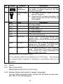
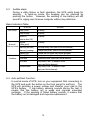
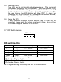
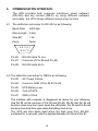
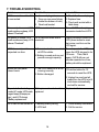
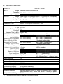
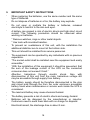
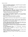
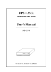
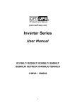
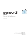
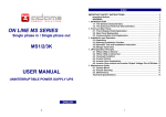
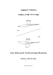
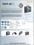
UPS + AVR
Uninterruptible Power System
User’s Manual
Sine Wave Line-Interactive
(Model : 5000VA)
5% or 8% for AVR
TABLE OF CONTENTS
FRONT PANEL --------------------------------------------------------------- Page 3
REAR PANEL ----------------------------------------------------------------- Page 3
1.
INTRODUCTION ----------------------------------------------------- Page 4
2.
MAIN FEATURES ---------------------------------------------------- Page 5
3.
CAUTION --------------------------------------------------------------- Page 5
4.
INSTALLATION AND OPERATION ----------------------------- Page 6 – 9
5.
INDICATION AND CONTROL ------------------------------------ Page 10 – 14
6.
COMMUNICATION INTERFACE -------------------------------- Page 15
7.
TROUBLE SHOOTING --------------------------------------------- Page 16
8.
SPECIFICATIONS --------------------------------------------------- Page 17
9.
IMPORTANT SAFETY INSTRUCTIONS ---------------------- Page 18 – 19
1
FRONT PANEL
Tower Type
Rack Mount Type
Introduction of LCD display
Load level
•
•
Mode & value
AC out
V
AC in
Hr. to ON
Min. to OFF
BATT.
SELECT
Battery level
1
TEMP.
POWER ON / OFF
SELF TEST
ALARM RESET
•
TIMER
•
•
LOW
HIGH
3
2
1
Main control button.
2
LCD screen.
3
Selection button for mode & value.
2
Rear Panel
I.
A.
B2.
B1.
H.
J.
K.
G.
F.
E.
D.
C.
A.
Inlet (screw type).
B.
Outlets
B1.
B2.
B3.
Universal sockets 2 x 2 + screw terminal x 1, or
IEC 5 sockets x 3, or
IEC 5 sockets x 2 + Germany type x 1
C.
Re-settable fuses for output.
D.
Re-settable fuse for input.
E.
SNMP slot.
F.
Cooling fan.
G.
RJ-11 port.
H.
DIP switch.
I.
Communication port (RS-232).
J.
Handles.
3
B3.
1.
INTRODUCTION
1.1 Overview:
The series UPS is an advanced Line-Interactive Uninterruptible Power
System which produces pure sine wave power to your equipment; unlike
the traditional off-line UPS, the series provide very short transference
when blackouts happen, and zero transference from AC mode to battery
mode or from battery mode to AC mode. The voltage regulation
performance of series is similar to an On-line UPS; however, the series
provide efficiency over 98% under normal power condition. Two charge
modes, quick charge and trickle charge, are provided to maintain the
batteries in the best condition.
1.2 Battery replacement warning
The self-test function (by pushing the button) will inform you with an
alarm when the batteries are weak and require replacement.
1.3 DIP Switches
DIP switches allow you to adjust the UPS for different line voltages and
frequencies in different areas. It also allows you to enable the green
power function to shut down the UPS automatically if the load is less than
25W, and then to extend the battery life.
1.4 Communication interface
3sets of communication ports (1set of RS-232/SNMP, and 2sets
RS-232/DB-9) for sensing input voltage, output voltage, battery
capacity, output power level, and UPS statuses are provided;
through this port, you can remote control the UPS for turning on and
off by customized schedule and setting the auto-test procedure.
1.5 Extra wide voltage of AVR
The AVR range for the model is made as precise as ±5% for output with
input range ±22% (or, upon request, ±8% for output with input range ±
35%).
1.6 Warning for failed battery (Real-time detection)
The battery self-detect function will run every 20 minutes (no need to
push the button by user). The “Battery replacement” symbol on LCD
panel will show up when battery failed or is in open circuit.
4
2.
MAIN FEATURES :
Pure sine wave output.
Zero Transference.
Line-Interactive structure.
Microprocessor based design.
RS-232 interface for communication.
‘Green Power’ designed with auto on/off function.
Protection for overload, short circuit, & over heat.
3.
CAUTION:
The UPS is designed to power computer loads and the associated
peripheral devices, such as monitors, modems, external H-Disk
drivers, etc. To ensure the performance of the UPS, Do Not load the
UPS with motor, or any type of inductive load.
Connecting the UPS to a two-pole, three-wire grounding mains
receptacle. Connection with any other type of receptacle may result
in a shock hazard and may violate local electrical codes.
Do not allow water or any foreign object to get inside the UPS.
do not put objects containing liquid on or near the unit.
And
Keep UPS away from fire or heating sources.
The standard models are shipped from the factory with fully charged
internal batteries; however, the batteries may lose some energy
during delivery and storage. To ensure that the UPS will provide
the expected run-time during a blackout, the UPS must be left in
charging for at least 5 hours before your first use. The batteries
are charged automatically by the UPS whenever the UPS is
connected with city power (No need to turn on the UPS).
5
4.
INSTALLATION13
& OPERATION:
4.1
Unpacking & Installation
4.1.1 Inspecting the packing carton for damage that may have occurred while
in transit. Immediately notify the carrier and place of purchase if any
damage is found. Retain the package for future use.
4.1.2 The packing of the UPS is separated into 3 units, main unit weight
39kgs, & 2 units of battery set weight 18kgs of each. Each battery
set contains 6pcs of 12V battery.
4.1.3 To move the units, main unit needs 2-3 persons; while the battery set
can be moved by one for each.
4.1.4 The UPS can be used as a rack-mount unit, or a tower one. Please
follow the steps to make it as a rack-mount unit or a tower one as
below:
4.1.4.1 Tower type --- To screw on the rubber pad (6pcs, as attached) at
the bottom side of the unit; or put on 4 wheels (optional).
Bottom side (with pads, or wheels)
4.1.4.2 Rack mount type --- to screw on the handling ears as a regular rack
mount unit, put it on the rack, and fix it.
Adjust the display panel between tower & rack mount types, you
can make it easily simply by screwing on/off the 4 screws around
the display panel with 90° turning on the panel.
6
4.1.5 To install the UPS, please fix the main unit first; then, put on the
battery set one by one, and finish the connection (Ref. 4.2); finally
make connection for input and output of the UPS.
4.1.6 To ensure that your computer or equipment will be protected during a
utility failure, it is important to make sure that the maximum power
needed by the equipment is not over the rated capacity of the UPS.
The over load mark on LCD panel will be lighted up and alarm will
beep if the load is over the rated value. Meantime, if the overload is
severe, the UPS will shut down immediately for protecting UPS itself.
4.2
Battery Installation / Replacement
4.2.1 This is a hot-swappable designed UPS, which means that when you are
replacing battery set, the UPS doesn’t need to be turned off.
4.2.2 To install or replace batteries, please screw off the 4 screws of front
panel, disconnect the cable connection to the LCD display module; then
please disconnect and pull out one of the two battery sets, and keep the
other set in connection so that your equipment can be still protected
during the period of time for battery replacement.
(DWG. 4.2.2-1
(DWG. 4.2.2-2
Front view of the unit)
Inside view when front panel is removed.
7
4.2.3 Please screw off the top cover of the battery set to be replaced, change
the batteries inside with the same spec. & number, and make it in series
connection.
(DWG. 4.2.3 Inside view of
battery pack when top cover
is removed.)
4.2.4 Put back the battery set in the main unit, finish the connection with the
UPS, and proceed the same steps for replacing the other battery set.
4.2.5 Once the battery replacement has been finished, please put back the
cable connection to the LCD module, and tightly screw on the front
panel.
4.2.6 The warranty will be void if to replace battery without the same spec or
number. The battery type is 12V 7Ah, 6pcs for each pack, and 12pcs
in total
4.3
Operation
4.3.1 After installation with normal city power, the UPS will charge the battery
automatically, and the battery symbol and battery level will blink every
second during charging. If AC auto turn-on function (Ref. 5.7) in
enabled, the UPS will turn on automatically when city power is green.
If auto turn on is disabled, please push the button about one second on
the front panel, then the UPS will give power to the outlets after a
short-time of self-test.
8
4.3.2 Pushing the button for 4 seconds, the UPS will turn off the power on the
outlets. But, the UPS will keep charging if city power is normal.
4.3.3 During a blackout, push the button for entering idle mode (Ref.
Indication Table of 5.3), then push again for one second, and the UPS
will be turned on and enter into backup mode. To turn off the power
from UPS; please push the button for 4 seconds, then UPS’s LCD
screen will show OFF, wait for 5 seconds, and UPS will turn off the
power automatically.
4.3.4 In idle mode, UPS will turn off the power automatically within 4
seconds during a utility failure; while UPS will keep charging the
batteries if the utility power is normal.
4.4
“Green mode” setting:
When “Green Power” function is enabled (Ref. to 5.7), the UPS will turn
off the power within 30 seconds after blackout occurs with the power
consumption lower than 25W.
4.5
Ring on function:
When you are connecting the phone line through the UPS. The UPS
may offer protection against damaging power fluctuations and surges
that travel through the phone line. The UPS also offers a ring on
function when the power is off. UPS power will be turned on
automatically when a ringing signal exists in the phone line, and the
UPS will keep power on until the UPS is turned off by button-pressing,
or by the green power function or by RS-232 interface.
4.6
Enable/disable silence mode:
The silence mode can be enabled or disabled only when the UPS is in
back up mode or test mode. To push the test button for 0.5 second
will enable/disable the silence mode. If UPS is in normal mode, UPS
will run test mode once you push the test button, silence mode can be
enabled/disabled during test mode.
9
5.
INDICATION AND CONTROL
5.1
Indication
LCD screen
5.
4.
15.
5 4
16
AC out
1.
2.
3.
V
AC in
2
BATT.
Min. to OFF
TEMP.
Hz
•
TIMER
3
No.
1.
Symbol
6 7
7.
8
8.
9
14.
14
15
LOW
HIGH
6.
13.
Hr. to ON
LOW
9.
10
10.
1111.12
12.
13
Indication
Over load
Description
The loading exceeds the rating of UPS.
2.
Load level
The higher the loading, the more bars will
illuminate.
3.
UPS is loaded
4.
Normal mode
When “Green Mode” is enabled, this symbol will
display if the loading is over 30W
(approximately), and disappears when it is under
25W (approximately). Refer to User’s Manual
4.3.5. If “Green Mode” is disabled, the symbol
will always display.
1) The sine wave symbol will display
steadily without battery symbol when
UPS is in the normal mode.
Battery mode
2) The sine wave symbol and battery
symbol will blink when the UPS is in
back-up (inverter) mode.
Test mode
3) The sine wave symbol will display
steadily with blinking battery symbol
when the UPS is in testing mode.
10
No.
5.
Indication
Buck mode
Description
The AVR (Auto Voltage Regulator) is reducing
the output voltage of the UPS (when the input
voltage is too high), and the sine wave symbol,
as mentioned in item 4, will also display steadily
to indicate that the output is in the normal mode.
6.
Boost mode
The AVR is increasing the output voltage of the
UPS (when the input voltage is too low), and the
sine wave symbol, as mentioned in item 4, will
display to indicate it’s in the normal mode
7.
Timer is enabled
8.
Symbol
HIGH
9.
10.
11.
12.
This symbol will show up in the following
situations:
1) A turn-on / turn-off schedule has been set
using the monitoring software. Refer to
User’s Manual 5.5 and the “Readme” file or
“Help” function of the monitoring software.
2) The Green Mode is enabled and the loading is
under 25W (approximately). The UPS will turn
itself off automatically in 30 seconds. Refer
to 4.4 of User’s Manual.
Thermal alarm
The temperature inside the UPS is over 55•. If the
user does not reduce the load, the temperature will
continue to rise and the UPS will shut down
automatically at 60•.
Fan is in “High This symbol is used only for long back-up
speed”
models and 5000VA model.
The symbol will display whenever the cooling
fan is running in high speed, and will disappear
at low speed.
Silence mode
The audible alarm has been silenced. To reset
the alarm in Back-up mode, push the control
button (not available during low battery level or
abnormal condition).
UPS fault
The UPS has failed and must be repaired.
Contact a qualified service person.
Battery normal
1) In normal operation, this symbol indicates a
charged battery.
Battery low
2)
LOW
11
When the battery charge level is low, the
word “LOW” will be added to the symbol.
No.
13.
Symbol
Indication
Battery
replacement
14.
Battery voltage
level
15. Mode
Value
Description
The battery has failed and must be replaced.
The battery is checked each time the Test
Function is executed.
1) The higher the battery voltage, the more
bars will illuminate.
2) When the UPS is charging the battery, the
battery symbol and the level indicator will
blink together.
Description
AC out
V
AC output voltage.
AC in
V
AC input voltage.
AC out
Hz
AC output frequency.
BATT.
V
DC battery voltage.
TEMP.
TIMER
•
Min. to off
UPS internal temperature.
The UPS will turn off when the displayed value
reaches zero. For example, if the timer
shows 0.5 Min to off, the UPS will shut down in
30 seconds.
TIMER
Hr. to on
The UPS will turn on when the displayed value
reaches zero. For example, if the timer shows
48.0 Hr to on, the UPS will turn on in 2 days.
BATT.
Min. to off
The estimated remaining run time in Back-up
mode. The accuracy of the value is influenced
by the loading type, ambient temperature and
battery condition (old or new).
Selection Button for mode & value.
All the operation data will be displayed on LCD screen.
By selecting
the required mode (upward or downward), the related value will be
displayed.
5.2
Control
5.2.1 Main control button:
Please refer to point 4 & 5 (4.3 & 5.3-5.4).
5.2.2 Selection Button (with symbol of upward / downward):
You may select a required mode, and the LCD will show you the value
(Ref. Item 15 of LCD description).
12
5.3
Audible alarm
During a utility failure or fault operation, the UPS emits beep for
warning. In back-up mode, the beeping can be silenced by
pushing the button. However, the warning of low battery will still
sound for urging user to leave computer without any data loss.
Basic Indication Table:
STATUS
Idle mode
Utility Good
No Beep
Utility outage
No Beep
Timer on,
(refer to Item 5.5)
No Beep
Normal
Normal /
(Utility good)
Back-up mode Back-up (No load)
Back-up (Loading)
Abnormal
Condition
ALARM
No Beep
One beep every 4 sec (alarm can be silenced).
2 beeps every 4 sec. (alarm can be silenced).
Battery Low
4 beeps per sec (alarm can Not be silenced).
Battery NG.
8 beeps per sec (alarm auto stop after 8 seconds).
Over load
UPS fault
Continuous alarm (alarm can Not be silenced).
Every other 2 sec., 32 beeps in 2 sec
(alarm can Not be silenced).
Every other 2 sec., 32 beeps in 2 sec
(alarm can Not be silenced).
Thermal alarm
5.4 Auto self-test Function:
In normal mode of UPS, turn on your equipment that connecting to
the UPS and push the button on the front panel for self-test. The
UPS will simulate a power outage and transfer your load to the
UPS’s battery. If low battery warning sounds during the test, it
means that the battery set is weak and requires extended
recharge. If the warning of failed battery sounds, it means that
the battery set is damaged and requires replacement.
13
5.5
Remote Control:
The UPS can be set for daily shutdown/wake up. This command
must be set through the RS-232 interface. When this function is set,
the timer inside the UPS will begin to run, and the load will be turned off
by the shutdown/wake up schedule. During the period of turn off to
the next turn on, the LCD display will show “OFF”, to check the
remaining time to the next turn on, please push the selection buttons,
the LCD will show the remaining time in hours.
5.6
Reset the UPS
If any abnormal condition occurs, and the item 4.3 can not be
executed, please push the button for at least 10 sec. when all the
LCD data disappear, then the UPS is reset.
5.7 DIP Switch Settings
DIP Switch
1
2
3
4
DIP switch setting
DIP 1
DIP 2
220V System
110V System
Down
Up
220V / 60Hz
100V / 50Hz
Up
Up
220V / 50Hz
110V / 60Hz
Up
Down
230V / 50Hz
115V / 60Hz
Down
Down
240V / 50Hz
120V / 60Hz
DIP 3 for AC Auto turn-on when city power returns
UP = Enable / Down = Disable
DIP 4 for Green Mode setting
UP = Enable / Down = Disable
P.S.: Program setting active only after the UPS is re-started.
14
6.
COMMUNICATION INTERFACE:
The UPS provides both computer interfaces, smart software
(RS-232) and dry contact (DB-9); by using different software
and cable, the UPS shows different monitoring function.
6.1 The definition and setup for RS-232 is as following:
Baud Rate
: 2400 dps
Data Length : 8 bits
Stop Bit
: 1 bit
Parity
: None
5 4 3 2 1
9 8 7 6
Pin #6 : RS-232 data Tx out.
Pin #7 : Common of Pin #6 and Pin #9
Pin #9 : RS-232 data Rx In
6.2 The definition and setup for DB9 is as following:
Pin #2 : AC Power Failure
Pin #4 : Common GND of Pin #2 & Pin #5
Pin #5 : UPS Battery Low
Pin #6 : Turn off UPS
Pin #7 : GND of Pin6
The interface with computer is diagramed as above for your reference.
Use Pin #4 as the common of Pin #2 and Pin #5, Pin #2 and Pin #4 will
become close loop from open when the utility fails, Pin #5 and Pin #4 will
become close loop from open when the battery level is low.
The UPS will shut down itself when the high level from RS-232,
sustained for 3 seconds, which is applied between Pin #6 and Pin #7.
15
7. TROUBLE SHOOTING
Problem
Possible Cause
UPS no reaction while AC 1. Line cord plug is loose
is connected
2. Fuse on rear panel blown
(Inside the drawer of inlet)
3. Dead wall socket
Action to Take
1. Check the line cord plug
2. Replace fuse
3. Check wall socket with a
table lamp.
Power output is normal, UPS UPS is over loaded
emits continuous beep, LCD
shows “Overload”.
Turn off UPS and unplug
excessive loads from UPS.
No power on outlets, UPS
UPS has shut down due to
emits continuous beep, LCD overload.
shows “Overload”.
Unplug excessive loads from
UPS, press button to reset
the buzzer, and turn on the
UPS again.
UPS does not provide
expected run time
1. Excessive loads connected
at UPS’s outlets.
2. Battery is weak and can not
provide enough capacity.
Do not operate the UPS, and
leave the UPS plugged in for
10 hours. Then, test it
again, if UPS still can not
provide expected run time,
battery should be replaced.
Button on front panel
doesn’t work
1. The CPU inside UPS is not
running correctly.
2. Button damaged.
1.Push the button for 10
seconds to reset the UPS.
2. Unplug line cord and all
loads from the UPS to let it
shut down automatically,
and call for service.
To push button for testing
under AC mode, UPS emits
urgent beep (8 beeps per
sec.), and LCD shows
“Battery replacement”.
Battery is weak and should be Replace batteries.
replaced
UPS can not be turned on. 1. Battery polarity wrong
2. UPS fault
16
1. Check battery connection.
2. Call for service.
8. SPECIFICATIONS:
CAPACITY
INPUT
OUTPUT
5000VA / 3500W
Voltage Selectable 200/220/230/240V 1ø
Frequency
50Hz/60Hz Auto detect
Current (220V) 25A
Voltage Rated voltage ±3% for Back-up Mode, or • ±5% for AVR (or• ±8% optional)
Frequency 50Hz or 60Hz ± 0.1Hz (Selectable under DC start)
Wave Form Pure Sine Wave
Current (220V) 22.7A
TRANSFER TIME
Blackout 3.5 ms typical or Brownout < 1ms
BATTERY
Lead-Acid, maintenance free
12V 7Ah
12pcs
YES
Within 2 hrs
LCD (symbol shown up)
Alarm
Sine Wave
No beep
Sine Wave+ Battery
B-B-----B-B----- (2 beeps/4sec.)
Sine Wave+ Battery
B-B-----B-B----- (2 beeps/4sec.)
(Transfer to backup mode)
Sine Wave+ Battery
B-B-----B-B----- (2beeps/4sec.)
(Transfer to backup mode)
Sine Wave
No beep
+ Buck or
(AVR in operation)
+ Boost
B-B-B-B-B-B-------- (4 beeps/sec.)
Sine Wave+ LOW+ Battery
Battery replacement
BBBBBBBB
(8 beeps/sec.)
Over load
B……….. (continuously)
High Temp.
G
. R
.
TYPE
Battery quantity
Level Ind.
Recharge Time (to 90%)
OPERATION INDICATION
Normal city power
Back up Mode
Abnormal Freq. of City power
(Freq. > 65Hz or < 47Hz)
Abnormal V. of City power
(Voltage > 122% or< 80%)
Abnormal V. of City power
(Voltage<122% but>105%or
>80% but <95%)
Low Battery Alarm
Battery Fail Alarm
Over load Alarm
Thermal Alarm
(G = 32beeps/2sec. R = silence / 2sec.)
Safety Approval
Remaining Backup Time
DC Start / Alarm Reset
Communication Interface
Environment Temp.
Environment Humidity
Dimensions (H x D)
Shipping Dimensions
CE
YES
YES
RS-232*1
0 - 40
30-95% Non-Condensing
4u x 52cm
Separate packing carton for main unit (64x60x40cm) & battery
packs (45x18x13cm) * 2sets; and, about 6 -10 sets per pallet.
Weight (N.W. / G.W. Kg)
70 / 74
• Specifications subject to change without prior notice.
17
9.
IMPORTANT SAFETY INSTRUCTIONS
•
When replacing the batteries, use the same number and the same
type of batteries.
•
Do not dispose of batteries in a fire; the battery may explode.
•
Do not open or mutilate the battery or batteries, released
electrolyte is harmful to the skin and eyes.
•
A battery can present a risk of electric shock and high short circuit
current. The following precaution should be observed when
working on batteries.
* Remove watches, rings or other metal objects.
* Use tools with insulated handles.
•
To prevent an overbalance of this unit, with the installation the
additional stabilizer are to mount at the bottom side.
•
This unit should be installed from service personnel.
•
The equipment can be operated by any individuals with no previous
experience.
•
“The socket-outlet shall be installed near the equipment and easily
accessible.”
•
“With the installation of this equipment it should be prevented, that
the sum of the leakage current of the UPS an the connected
consumer does not exceed 3.5mA.”
•
Attention, hazardous through electric shock. Also with
disconnection of this unit from the main, hazardous voltage still
may be accessible through supply from battery.
•
The battery supply should be therefore disconnected in the plus
and minus pole through the from the outer enclosure accessible
battery fuses when maintenance or service work inside the UPS is
considered.
•
The lead acid battery may cause chemical hazard.
•
The battery presents a risk of electric shock and energy hazard.
•
Batteries will be disposed by the manufacturer or importer.
Customers need to send them back with no charge for disposal.
•
Electrical hazard, the discharge time is about 5 min.
18
German wording:
•
•
•
•
•
•
•
Wenn Sie die Batterien austauschen, verwenden Sie bitte die gleiche
Anzahl und den gleichen Batterietyp.
Werfen Sie niemals die Batterien in das Feuer, die Batterien könnten
explodieren.
Öffnen oder beschädigen Sie nicht die Batterien, ausfileβendes Elektrolyt
ist schädlich für Haut und Augen.
Eine Batterie kann eine Gefahz eines elektrischer Schlages und sehr
groβer Kurzschluβströme beinhalten. Folgenda Vorkehrungen soiiten
getroffen warden, wenn Sie mit der Battery arbeiten.
* Entfernen Sie Uhren, Ring and andere metallische Objekte.
* Verwenden Sie Werkzeug mit isolierten Griffen.
Um ein Umkippen dieses Gerätes zu verhindern, sind mit der Installation
dieses Gerätes die zugätalichen Stützen an der Unterseite dieses
Gerätes anzubringen.
Dieses Gerät ist durch Elektrofachkräfte zu installieren.
Bedienung durch jedermann ohne dem Vorkenntnisse.
•
“Die Steckdose muβ nahe dem Gerät angebracht und leicht zugänglich
sein.”
•
“Bei der Installation dieses Gerätes ist darauf zu achten, daβ die Summe
der Ableitstöme der USV und der angeschlossenen Verbraucher den
Maximalwert von 3.5mA nicht Überschreiten.”
“Vorsicht, Gefahr durch elektrischen Schlag. Auch nach Trennung von
der Netzeingangsspannung werde Teile innerhalb der USV von der
Batterie gespeist und führen gefährliche Spannung.
Bei Instandhaltungsarbeiten ist daher die Versorgung durch die Batterie
an den von auβen zugänglichen Sicherungshaltern in beiden Polen zu
unterbrechen.”
Die Blei-Akkumulatoren Können bei unsachgemäβer Handhabung
chemische Gefahren hervorrufen.
Die Batterie birgt eine Gefahr eines elektrischen Schlages und sehr
hoher Kurzschluβstroeme.
Batterien werden durch den Hersteller oder Importeur entsorgt. Dazu
muessen die Batterien kostenfrei angeliefert werden.
Gegahr durch elektrischen Schlag, die Entladeit dieser Kondensatoren
beträgt 5 min.
•
•
•
•
•
•
19