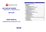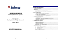
1
Index
SINUS SERIES
Uninterruptible Power System
ONLINE UPS
Single phase in / Single phase out
1kVA – 3kVA
USER MANUAL
0
.
Important Safety Instructions
Important Notices -----------------------------------------------------2
W arning --------------------------------------------------------------3
1. Introduction
1.1. T h e G e n e r a l C h a r a c t e r i s t i c s - - - - - - - - - - - - - - - - - - - - - - - - - - - - - - - - - 4
1.2. T h e A d v a nc ed T ec hnic al Char ac ter is tic s - - - - - - - - - - - - - - - - - - - - - 5
2. Front and Rear Panel
2.1.Front Display Panel Explanation----------------------------------6
2.2.Rear Panel Explanation-------------------------------------------7
2.2.1.G ener al Ex planation---------------------------------------------7
2.3.Communication Port Explanation------------------------9
3. Installation and Operation
3 . 1.Unpack ing-----------------------------------------------------------10
3.2.Selec ting Ins tallation Position----------------------------------10
3.3.O per ation T es t and Ins tallation Instruction-----------------11
3.4.Stor age Instruction------------------------------------------------12
4. UPS Operation Principle
4.1.W hen Utility is Norm al--------------------------------------------13
4.2.W hen Utility is Abnorm al-----------------------------------------13
4.3.Overload Condition--------------------------------------------------14
4.4.Inverter Failure------------------------------------------------15
4.5.Inverter Over Tem perature---------------------------------------15
4.6.Inverter Over-current and Inverter Output Voltage Out of Window--15
5. Maintenance Guide
5.1. System Block Diagram ------------------------------------------16
5.2. Troubleshooting-----------------------------------------------------16
5.3. Maintenanc e-------------------------------------------------------17
Technical Specification----------------------------------------------18
1
IMPORTANT SAFETY INSTRUCTIONS
•
*Save these instructions
This manual contains important instructions that should be followed during
installation and maintenance of the UPS and batteries.
WARNING:
Important Notices:
•
•
•
•
•
•
•
•
•
•
•
•
•
•
•
•
•
•
To ensure safety in all applications where an UPS is hard wired to the Electrical Supply,
ensure that the system is installed by authorized staff.
Those UPS systems supplied with a factory input lead can be safely connected to the
wall socket by the purchaser.
The UPS has its own internal energy source(battery). Should the battery be switched
on when no AC power is available, there could be voltage at the output terminals.
Make sure that the AC Utility outlet is correctly grounded.
Do not open the case as there are no serviceable parts inside. Your Warranty will be
void.
Do not try to repair the unit yourself, contact your local supplier or your warranty will
be void.
Please make sure that the input voltage of the UPS matches the supply voltage.
Use a certified input power cable with the correct plugs and sockets for the
appropriate voltage system.
To eliminate any overheating of the UPS, keep all ventilation openings free from
obstruction, and do not store "things" on top of the UPS. Keep the UPS 20 cm away
from the wall.
Make sure the UPS is installed within the proper environment as specified. (0-40°C
and 0-95% non-condensing humidity)
Do not install the UPS in direct sunlight. Your warranty may be void if the batteries
fail.
Install the UPS indoors as it is not designed for installation outdoors.
Dusty, corrosive and salty environments can do damage to UPS.
Install the UPS away from objects which give off excessive heat and areas which are
excessively wet.
If liquids are split onto the UPS or foreign objects dropped into the unit, the warranty
will be null and void.
The battery will discharge naturally if the system is unused for any length of time.
It should be recharged every 2-3 months if unused. If this is not done, then the
warranty will be null and void. When installed and being used, the batteries will be
automatically recharged and kept in top condition.
This UPS supports electronic equipment in offices, telecommunications, process
control, medical and security applications.
2
This UPS has been designed and constructed to protect your assets from the wide
range of power aberrations experienced on Utility power lines today. It is your
insurance for reliable, clean and stable voltage supply. It is worth taking care to
install the system correctly and to have it maintained correctly by your local distributor.
•
•
•
•
•
•
•
•
This is a Class A-UPS Product. In a domestic environment,
This product may cause radio interference, in which case,
The user may be required to take additional measures.
Intended for Installation in a Controlled Environment.
Servicing of Batteries Should be Performed or Supervised by Personnel
Knowledgeable of Batteries and the Required Precautions. Keep Unauthorized
Personnel Away from Batteries.
When Replacing Batteries, Replace With the Same Number and Type.
CAUTION – Do Not Dispose of Battery or Batteries in a fire. The Battery May Explode.
CAUTION – Do not open or mutilate the battery or batteries. Released electrolyte is
harmful to the skin and eyes. It may be toxic.
CAUTION – Risk of Electric Shock – Battery Circuit is not isolated from ac, hazardous
Voltage may exist between battery terminals and ground. Test before touching.
CAUTION – A Battery can present a Risk of Electrical Shock and High Short Circuit
Current. The Following Precaution Should be Observed When Working on Batteries:
A. Remove watches, rings, or other metal objects.
B. Use tools with insulated handles.
C. Wear rubber gloves and boots.
D. Do not lay tools or metal parts on top of batteries.
E. Disconnect charging source prior to connecting or disconnecting battery terminals.
CAUTION – To reduce the risk of fire, connect only to a circuit provided with
50 amperes maximum branch circuit over current protection in accordance
with the National Electric Code, ANSI/NFPA 70.( 3KVA)
3
INTRODUCTION
1.1.
•
•
•
•
•
•
•
.
.
The General Characteristics
True online architecture continuously supplies in your critical device with
a stable, regulated, transient-free pure sine-wave AC Power.
50KHz PWM sine-wave topology yields an excellent overall performance.
The high crest factor of the inverter handles all high-inrush current
loads without a need to upgrade the power rating.
To protect the unit from overloading, it automatically switches to bypass mode
in case loading exceeds 120% of rating. It will automatically switch back to
inverter mode once overload condition ceases.
Should the output becomes short-circuited, the UPS holds the system
and cuts the output automatically till the short circuit situation is removed.
Should the unit become overheated, the internal thermistor will detect
the heat and switch to bypass mode and vice versa.
Maintenance-free sealed-type battery minimizes after-sales service.
1.2. The Advanced Technical Characteristics
Market leading light and compact design for modern OA environment.
Powerful CPU integrates all power stages, control and communication
functions necessary for maximized UPS protection and functionality, including
Power management status monitoring, configuration setting operation
Scheduling, remote control and self-diagnosis.
Slick CPU communication design allows full function remote control from any
computer environment via standard RS-232 interface.
State of the art IGBT Technology and Industrial Grade quality ensures
Highest efficiency and reliability under tough operating condition.
Industry leading inverter protection technology incorporates 2-stage output
Current sensor, smart overload output current control, improved crest factor,
and feedback failure proof circuit, elevating the availability of power service.
Guarantees an exclusive protection against DC damage for inductive load,
Such as motor based devices, entirely eliminating application limitation.
Advanced Input PFC control guarantees the PF performance and maximum
energy efficiency.
Unique electronic over-current protection detects output short-circuit and
faults, and halts output before damages done to output fuse or equipment,
thereby minimizing the need for service.
Expanded input voltage working range minimizes battery usage and
enhances battery utilization and life.
Automatic Frequency Sensor reduces troubles in frequency shift.
Cold start function makes sure of the start-up of UPS during power outages.
On-demand self-diagnosis function ensures UPS reliability and availability.
Built-in supplementary charger enables speediest charging of external battery
Bank.
User's adjustable Output DIP switches allow you to select an accommodate
Output voltage for your critical device.
4
5
Front and Rear Panel
2.1.
.
1.
2.
3.
Main Switch
Self Test OK LED
Test/Silence
4.
5.
6.
Fault LED
Bypass LED
Utility LED
7.
Inverter LED
8.
Battery low LED
9.
Over load LED
2KVA
Rear Panel Explanation
2.2.1 General Explanation
Front Display Panel Explanation
1KVA
2.2.
3KVA
This is control the on/off of the UPS
Green LED lights up if self test is O.K.
a. To silence alarm by pressing the button.
b. To execute the self test of the UPS by pressing
the button over 10 sec.
c. To illustrate the percentage of output load level at
AC Mode, and the battery energy level at Backup
Mode by pressing the button.
Red LED lights up if UPS is faulty.
Amber LED lights up when UPS is in Bypass mode.
a. AC normal: Green LED lights up.
b. 100% for load & battery level
a. Inverter On: Green LED lights up
b. 75% for load & battery level.
a. Battery low : Red LED lights up
b. 50% for load & battery level
a. Over load condition: Red LED lights up
b. 25% for load & battery level.
6
7
1) AC Inlet
2) AC Input
Fuse/
Breaker
3) External
Battery
Terminal
This is to be connected with an AC power cord for plugging
into the wall receptacle.
This is to disconnect line input to protect application from
Output overload or short circuit.
Fuse/Breaker Rating for 220V/230Vac systems
1KVA
2KVA
3KVA
220V/230Vac:
220V/230Vac:
220V/230Vac:
10A/250V
20A/250V
25A/250V
This is a battery terminal to be connected with additional
battery banks for longer backup time purpose. Only a
qualified technician is permitted to proceed the installation.
4) AC OUTLET Socket Type 1KVA
2KVA
3KVA
IEC
3pcs
3pcs
N/A
Schuko
1pc
2pcs
2pcs
Sockets
6) Comm Port This is an interface to send signals to and receive signals
from the computer. An optional computer software may be
required. Please refer to Chapter 2.3 for its pin
assignments.
7) RJ11/RJ45 This is to offer you a modem/internet(RJ11) and 10-Base T
Jack
Network(RJ45) protection against line interference.
8) DIP
Switches
2.3.
Communication Port Explanation
The communication port on the rear panel of the UPS is a true RS232
serial type. It may be connected to a computer and allows the computer
to monitor the status of UPS, and controls the operation of the UPS, via
an additional UPS software kits. The bundled software of the UPS is for
Windows environment, such as Windows 3.1, Windows 95 & 98,
Windows NT. For other applications, such as Novell NetWare, Unix,
etc., please contact your local distributor for a proper solution.
2.3.1. The RS232 interface settings
The RS232 interface shall be set as follows:
Baud Rate
: 2400 bps
Data Length
: 8 bits
Stop Bit
: 1 bit
Parity
: None
2.3.2.
The Pin Assignments of true RS232 type
The Pin Assignments of true RS232 type are illustrated as follows:
9
8
7
6
For Calibration.
8
5
4
3
2
1
Pin 6: RS232 Rx
Pin 9: RS232 Tx
Pin 7: Ground
9
Installation and Operation
.
The packing condition and the external outlook of the unit should be inspected
carefully before installation. Retain the packing material for future use.
4. Do not place the UPS in an
environment near dusty, corruptive or salty
material or flammable objects.
3.1.Unpacking
1. Take the UPS out of the PE foam.
2. Unwrap the UPS.
a. The UPS itself is approx. 12.5~39kgs, so be careful when unpacking and
lifting the unit. Improper use of force might harm yourself.
b. The plastic bag holding the UPS is very slippery, so be careful in
Unpacking and holding the unit. The unit might drop accidentally
and harm yourself.
3. Standard Package includes:
- User's Manual
- AC Input Power Cord ( Not available for hard wiring connection models)
- IEC output cables ( for the UPS with IEC sockets only)
- RJ11 Phone Jack Cable
- UPS communication kit (optional)
3.2.Selecting Installation Position
It is necessary to select a proper environment to install the unit, in order to
minimize the possibility of damage to the UPS and extend the life of the UPS.
Please follow the advice below:
1. Keep at least 20cm(8 inches) clearance
from the rear panel of the UPS to the wall.
5. Do not expose the UPS to outdoors.
3.3.Operation Test and Installation
Instruction
The installation should be conducted or
supervised by a qualified technician to
avoid accident. Charge the UPS for
more than 8 hours after unpacking to
ensure the UPS is fully charged before
usage.
1. Make sure the grounding of wall
receptacle is properly done.
2.Verify if the voltage and frequency
ratings match that of Utility, then
connect the AC Input power cord to a
verified grounded 3-wire receptacle.
2. Do not block the air-flow to the ventilation
openings of the unit.
3. Please check the installation site to avoid
overheat and excessive moisture.
3.Turn on the Main switch on the front
panel to start the UPS, then the fan
on the rear panel will spin.
4. After 7~10 seconds, the start-up of
UPS will be completed, then the
"Utility" LED and Inverter" LED will
light up simultaneously.
5.Disconnect the input power cord of the UPS to see whether the UPS
remains operation when Utility is abnormal.
10
11
6. Re-connect the input power cord of the UPS to wall receptacle, then
connect the power cord of your device to the output receptacle of the
UPS.
7.Turn on the Main switch on the front panel. The "Utility" LED and "Inverter"
LED will light up in 7~10 seconds, then turn on the switch of the device
connected. Do not execute any critical application yet!
8.Disconnect the UPS from the wall receptacle to simulate Utility failure. The
"Utility" LED should extinguish and the alarm will sound continuously till
battery cutoff. The device connected to the UPS shall operate continuously.
To mute the audible alarm, please push the Test/Silence Button on the front
panel.
9.Your installation is done successfully.
3.4.
UPS Operation Principle
.
4.1. When Utility is Normal
The working principle of the UPS under Utility normal condition is
illustrated as follows,
RECTIFIER
O/P
OUTPUT
Storage Instruction
For extended storage through moderate climate, the batteries should be
charged for 12 hours every 3 months by plugging the UPS power cord into
the wall receptacle. Repeat this every 2 months under high temperature
environment.
--- 4-1 ---
When Utility is normal, the AC source is rectified to DC, partially fed into the
charger to charge battery and partially fed into inverter. The inverter reverts the
DC to AC to supply energy to the load connected. The Utility LED and Inverter
LED Light up.
4.2. When Utility is Abnormal
The working principle of the UPS under Utility abnormal condition is
illustrated as follows,
O/P
OUTPUT
--- 4-2 ---
12
13
When Utility is abnormal, the UPS will use the battery energy automatically to
energize the Inverter, and turn off the charger and AC/DC converter. The inverter
revert DC to AC to supply energy to the output load connected. The Inverter LED
lights up.
When Utility is back to Normal, the UPS will turn on the AC/DC converter, turn off
DC/DC converter and turn back charger to charging position. It has the same
working principle as figure 4.1.
During a blackout, the UPS will work as illustrated in figure 4.2. When Battery is
low, buzzer will beep continuously till battery is completely cut off. The battery low
protection of the UPS will cut off battery supply before battery drains to avoid from
battery over-drain. The Inverter LED and Bat. Low LED will light up till the UPS is
completely cut off. The UPS will re-start automatically when Utility is back to
Normal. The working principle is the same as figure 4.1.
4.4. Inverter Failure
4.4.1. Output short circuit under inverter mode
If output load is short circuited under inverter mode, the UPS will turn off the
output to prevent load from damage. The Fault LED lights up and the
buzzer sounds continuously. The UPS can not turn on automatically after
short circuit condition is eliminated. You are required to re-start the UPS
manually. To re-start the UPS after short circuit condition is removed, you
shall push the Main Switch on the front panel to "OFF" position first, then
to "ON" position again.
O/P
OUTPUT
4.3. Overload Condition
The working principle of the UPS when overloading is illustrated as follows;
--- 4-4 ---
4.4.2. Output Short circuit under bypass Mode
O/P
OUTPUT
If output load is short circuited under bypass mode, the AC fuse will trip
open to prevent the output load from damage. You shall replace a new
fuse with same rating after the short circuit condition is eliminated.
4.5. Inverter Over temperature
--- 4-3 ---
Normally, an inrush current is generated when switching on the connected device.
If the UPS is in 105~120% loading, it will switch to bypass mode in 60 seconds. If
The UPS is in 120%-150% loading, it will switch to bypass mode in 10 seconds. If
The UPS is over 150% loading, it will switch to bypass mode immediately. The
Utility LED, Bypass LED and Over Load LED light up. If overload condition is
eliminated by reducing the load to 80%~90%, the UPS will switch back to Inverter
mode automatically.
If the UPS experiences over-temperature when Utility is normal, it will
switch to bypass loop. The UPS will switch back to inverter mode when the
over-temperature situation is eliminated. If it happens when Utility is
abnormal, the buzzer will beep continuously and the Fault LED will light up.
The output of the UPS will also be cut off.
4.6. Inverter Over-current and Inverter Output Voltage Out of Window
If the UPS inverter delivers over-current and out-of-window voltage to
output, the UPS is out of order. The UPS will switch to bypass loop when
Utility is normal. The Utility LED, Bypass LED and Fault LED will light up.
If these two conditions occur when Utility is abnormal, the UPS will turn off
the Output and the Fault LED will light up.
14
15
Maintenance Guide
.
Situation
Battery Low LED lights up
5.1. System Block
Fault LED lights up
PFC
AC/DC
INVERTER
DC/AC
Control
Circuit
BOOST
DC/DC
CHARGER
System fails to backup when
Utility fails.
BATTERY
UPS is normal but no Output
to load
5.2 Trouble Shooting
When the UPS malfunctions during operation, you may check the list
Below for proper adjustment. Should the problem persists, please Contact
your local distributor for help.
Situation
Utility LED is not on and the
UPS is on battery mode, when
Utility is normal.
Check Items
AC Input cord is
loose or AC Input
fuse is broken.
The UPS switches to battery
3. Check if any
mode then back to Utility
power strip is
mode, when connected device
connected
is turned on. Or, the UPS
to the UPS.
Switches back and forth
4. Any damage of
between battery and Utility.
Wall Receptacle.
Overload LED lights up
16
Solution
1.Connect the AC Input
cord to wall receptacle.
2.Replace the AC fuse
with same rating one.
3.If problem persists,
please call for service.
1. Do not use power strip.
2. Replace the wall
receptacle.
Strange noise and smell
Check Items
Solution
Battery is running out.
Please proceed to shutdown
your load & application
Immediately then recharge
the battery.
Disconnect the output load
immediately and re-switch
on the UPS to see if the
"Fault" LED Is still on. If not,
your output load has
probably been shorted.
Otherwise, call for service.
Disconnect the input power
cord from the rear panel and
re-turn on the front Switch to
see if the UPS is on again.
If not, call for service.
Check to see if all Check all outlets to see if
cords are properly they are properly connected.
connected as
desired.
Immediately shut down the
whole System. Disconnect
the power from the UPS and
call for service.
5.3. Maintenance
Clean the dust from the ventilation openings and intakes on the rear panel.
1. Turn off the UPS and wipe the casing with a damp cloth.
2. Periodically unplug the power cord of the UPS from the wall
Receptacle to test the batteries condition.
3. Be sure you have already saved your application before you proceed the battery
discharging capability test.
UPS is overloaded.
Please remove some load
at the output end of the
UPS till the RED LED
extinguishes.
17
Technical Specifications
MODEL
INPUT
Voltage (Vac)
Frequency (Hz)
Phase
Input Power
Factor
OUTPUT
Voltage (Vac)
Capacity(VA/W)
Wave Form
Voltage Regulation
Frequency Stability
Synchronization
Crest Factor
Transfer Time
(Line Fault)
Efficiency (AC to
AC)
Run Time(Full
Load)
Cold Start
BATTERY
Type
Quantity (pcs)
Voltage (Vdc)
Recharge Time
DISPLAY
LED
1KVA
MODEL
2KVA
3KVA
160~280
50 / 60±5%(Auto Sensing)
Single
> 0.98(Full Load)
PROTECTION
Overload
Short Circuit
Overheat
220/230/240
1000/700
2000/1400
3000/2100
Sine Wave, THD<3%(no load to full load)
±2%
±0.5Hz (Free Running)
1 Hz/Sec. Slew Rate: Inverter Free Running If Input
Frequency Over ±5% Range
3:1
0 ms
> 85%
8 Min.
7 Min.
8 Min.
Yes
Sealed Maintenance Free Lead Acid
3
6
36
72
8 Hours To 90%
8
96
Utility, Battery Low, Inverter, Bypass, Self-Test, Load
Level, Battery Level, Overload, Fault Conditions
18
High Voltage
Trip-Off
Battery Low
Noise Suppression
Spike Suppression
ALARM
Audible and Visual
1KVA
2KVA
3KVA
100%~120% delay 60 seconds before switching to
bypass; 120%~150% delay 10 seconds before switching
to bypass; >150% immediately switch to bypass
a) Inv. Mode: UPS shutdown and Cut the Output.
b) Bypass Mode: AC Input fuse Breaks down.
a) Utility Normal: Switch to Bypass.
b) Utility Abnormal: Buzzer sounds continuously,
Fault LED lights up then cut the output.
Switch to Backup Mode
Alarm continuously till battery cutoff
Comply with EN50091-2.
Comply with EN61000-4-5.
Line Failure, Battery Low, Transfer to Bypass, Overload,
System Fault Conditions
PHYSICAL
147x223x401
130x365x479
190x365x453
Dimensions
(WxHxD, mm)
Net Weight (Kgs)
15
27
36
ENVIRONMENT
Temperature
0C~40C
Humidity
0~95% RH Maximum, Non-Condensing
Noise
<45 dB (at 1 meter)
COMPUTER INTERFACE
Interface Type
Standard RS232 Interface
SAFETY CONFORMANCE
Safety Standard
EN50091-1
EMC Standard
EN50091-2
Marks
CE,
19