1
WooKong Multi-Rotor
User Manual
V 3.9
2013.03.22 Revision
www.dji-innovations.com
1
Warning & Disclaimer
WKM is an excellent autopilot system offering excellent flight features for low altitude multi rotor, working in
restricted space compared to a conventional RC helicopter. It is not a toy when installed in multi rotors of any
size. Despite our efforts in making the operation of the controller as safe as possible when the main power
battery is connected, such as: disabling MC signal to ESCs when USB is connected; disabling throttle input
and stick command when throttle stick is not at the lowest position on power up, we strongly recommend
users to remove all propellers, use power supply from R/C system or flight pack battery, and keep children
and animals away during firmware upgrade, system calibration and parameter setup.
As DJI Innovations has no control over use, setup, final assembly, modification (including use of
non-specified DJI parts i.e. motors, ESCs, propellers, etc.) or misuse, no liability shall be assumed nor
accepted for any resulting damage or injury. By the act of use, setup or assembly, the user accepts all
resulting liability.
DJI Innovations accepts no liability for damage(s) or injuries incurred directly or indirectly from the use of this
product. Please read this manual carefully and strictly follow the steps to mount and connect the WooKong
for Multi Rotor (WKM) system on your multi rotor, as well as to install the Assistant software on your
computer.
Please observe all local laws and regulations of the country you are operating the equipment in.
For example:
AMA’s (Academy of Model Aeronautics) National Model Aircraft Safety Code, USA
BMFA (British Model Flying Association) Model Aircraft Safety Code.
CAA (Civil Aviation Authority) Model Aircraft and UAV Codes of practice.
DMFV (German Model Flying Association) Model Aircraft Safety Code.
These are only a few examples; please investigate the laws and regulations for your particular location.
Never fly over others or near crowds.
DJI and WooKong is registered trademark of DJI Innovations. Names of product, brand, etc., appearing in
this manual are trademarks or registered trademarks of their respective owner companies. This product and
manual are copyrighted by DJI Innovations with all rights reserved. No part of this product or manual shall be
reproduced in any form without the prior written consent or authorization of DJI Innovations. No patent liability
is assumed with respect to the use of the product or information contained herein.
©2012 DJI Innovations. All Rights Reserved.
2|
WKM Profile
DJI WooKong for multi-motors (WKM) is an autopilot system designed for serious multi-rotor enthusiasts
providing excellent self-leveling and position holding, which completely takes the stress out of flying RC
multi-rotors for both professional and hobby applications. WKM can be installed in a variety of models from
quad-rotor to octo-rotor.
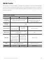
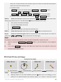
WKM Control Modes
GPS Atti. Mode
Atti. Mode
Manual Mode
Maximum angular velocity is 150°/s.
Command
Multi attitude control; Stick center position for
Stick Meaning
0˚ angle, stick endpoint is 35˚ angle.
No attitude angle limitation and
vertical velocity locking.
Command
YES
Linearity
Locks multi-rotor
Only attitude
Stick Released
position when GPS
NOT Recommend
stabilization.
signal is adequate.
Maintains the altitude, best above 1 meter
NO
Altitude Lock
from the ground.
When the GPS signal
Only attitude
is lost for more than
stabilization, GPS /
GPS Lost
10seconds, the
GPS not used
position lock not
system enters Atti.
used in this mode.
Mode automatically.
Mixture of Attitude & speed control ensures
Depends on experience.
Safety
stability; Enhanced FailSafe
Applications
AP work
©2012 DJI Innovations. All Rights Reserved.
Sports flying.
Extreme flying
3|
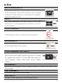
In Box
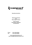
Main Controller (MC) ×1
The Main Controller (MC) is the brain of the system, it communicates with
the IMU, GPS/Compass,ESC’s and RC transmitter to carry out autopilot
functionality. The Main Controller has a USB interface for configuration
and firmware updates via a PC.
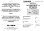
IMU ×1
The
Inertial
Measurement
Unit
(IMU)
consists
of
one
3-axis
accelerometer, one 3-axis gyroscope and a barometer. It is used for
sensing the attitude.
GPS & Compass ×1
The GPS/Compass module is for sensing the position and direction.
LED Indicator ×1
The LED indicates different states of system.
Power Management Unit (PMU) ×1
Specially designed for the WKM to convert the higher voltage of the
power circuit to the lower voltage required for the receiver etc. It contains
two regulated power outputs for the entire WKM control system and
receiver separately, a battery voltage monitor, and two CAN-Bus
interfaces.
GPS Bracket ×1
Because the GPS & Compass are sensitive to magnetic interference, you should use this bracket to mount
the GPS module.
PMU Connecter ×1
For connections between battery, ESCs and PMU.
USB Cable ×1
This cable is used to configure the MC and to update the firmware.
©2012 DJI Innovations. All Rights Reserved.
4|
3-PIN Servo Cable ×10
Cables used to connect the Main Controller to the RC receiver.
Mounting Pads ×4
For fixing WKM components on the multi-rotor’s frame.
Warranty Information Card ×1
It lists the necessary steps for using the WKM system and related safety advice. Please fill out the
customer & multi rotor information card and return to DJI Innovations to register your product warranty.
©2012 DJI Innovations. All Rights Reserved.
5|
Index
WARNING & DISCLAIMER ............................................................................................ 2
WKM PROFILE ............................................................................................................. 3
IN BOX ........................................................................................................................ 4
INDEX ......................................................................................................................... 6
IMPORTANT INFORMATION ........................................................................................ 7
ASSEMBLY ................................................................................................................... 9
ASSISTANT SOFTWARE............................................................................................... 10
SOFTWARE AND DRIVER INSTALLATION.....................................................................................10
GUI (GRAPHICAL USER INTERFACE) .........................................................................................10
FIRMWARE UPGRADE ...........................................................................................................12
PRODUCT INFO ...................................................................................................................12
CONFIGURATION ....................................................................................................... 13
1.
MOUNTING .............................................................................................................13
2.
MOTOR MIXER ........................................................................................................15
3.
TX MONITOR ...........................................................................................................17
4.
AUTOPILOT ..............................................................................................................21
5.
GIMBAL ..................................................................................................................33
6.
VOLTAGE MONITOR ..................................................................................................35
FLIGHT ...................................................................................................................... 39
DIGITAL COMPASS CALIBRATION ............................................................................................39
TEST FLYING .......................................................................................................................41
FLYING WITH GPS ...............................................................................................................43
ENHANCED FEATURES................................................................................................ 44
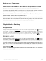
ATTITUDE CONTROL WHEN ONE MOTOR OUTPUT HAS FAILED ....................................................44
FLIGHT LIMITS SETTING ............................................................................................. 44
HEIGHT LIMIT .....................................................................................................................44
DISTANCE LIMIT ..................................................................................................................44
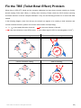
FIX THE TBE (TOILET BOWL EFFECT) PROBLEM ........................................................... 45
APPENDIX ................................................................................................................. 46
CUSTOMIZE MOTOR MIXER ...................................................................................................46
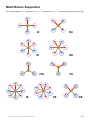
MULTI-ROTORS SUPPORTED ..................................................................................................51
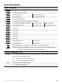
PORT DESCRIPTION ..............................................................................................................52
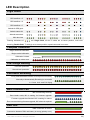
LED DESCRIPTION ...............................................................................................................53
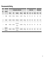
RECOMMENDED SETTING ......................................................................................................54
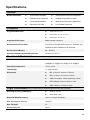
SPECIFICATIONS ..................................................................................................................55
©2012 DJI Innovations. All Rights Reserved.
6|
Important Information
For safety reasons, please pay serious attention to all following items:
1
Please disconnect the ESCs from the power battery or remove all propellers during firmware
upgrade, configuration and system setup.
2
Pay attention to the IMU mounting direction; Do not mount the IMU upside-down.
3
You have to reboot the MC and redo the TX calibration after you change the RC system.
4
In the TX Calibration menu of assistant software:
5
Throttle: Screen slider left is craft down, slider right is craft up
Rudder: Screen slider left is nose left, slider right is nose right
Elevator: Screen slider left is craft back, slider right is craft front
Aileron: Screen slider left is craft left, slider right is craft right
GPS/Compass is sensitive to magnetic interference; it should be mounted far away from any
electronic devices and motors.
6
Make sure you switch on the transmitter first, then power on the multi-rotor. Power off the
multi-rotor first, then switch off the transmitter after landing
7
Do not fly in GPS Mode when the signal is not good (red light blinks)
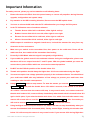
8
If you enable the gimbal control in the assistant software during the configuration, please note
that there will be an output from the F1 and F2 ports. With the gimbal enabled you must not
connect these ports to ESCs which are connected to motors/propellers.
9
Do NOT set the FailSafe position of the throttle below 10%.
10
Throttle stick position should always be higher than 10% from cut-throttle during the flight
11
You must set up the Low voltage protection properly in the assistant software. You should land
your multi-rotor ASAP after any indication of low voltage, to prevent your multi-rotor from
crashing or other harmful consequences
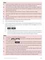
12
Using Immediately mode to stop motors: To start the motors you execute Combination Stick
Command (CSC) and push the throttle above 10% within 3 seconds, if the throttle is not above
10% within 3 seconds then the motors will stop. In any control mode, once motors start and
throttle stick is above 10%, motors will stop immediately when throttle stick is lowered below 10%
again. At this point, if you raise the throttle stick above 10%, within 5 seconds after motors stop,
motors will re-start with no need for Combination Stick Command (CSC). After 5 seconds you
will need to execute Combination Stick Command (CSC) to restart the motors.
13
Using Intelligent mode to stop the motors: The motors will start or stop immediately when you
execute Combination Stick Command (CSC). During normal flight, lowering the throttle stick
below 10% will not stop the motors in any control mode. If you execute CSC during flight then
©2012 DJI Innovations. All Rights Reserved.
7|
the motors will stop, you will have to execute CSC again to re-start the motors if they stop
during the flight.
14
When you set Mixer Type from Octo-rotor to Quad-rotor / Hexa rotor, the gimbal setting will
automatically switch to off for safety, which may lead the gimbal to tilt to one side, please turn
to the Gimbal section for reconfiguration.
15
It is strongly recommended to install the receiver under the bottom board of the center frame,
with the antennas pointing downwards without any obstacle. Control of the aircraft could be
lost if the radio signal is lost due to an obstacle (such as the base plate).
16
Make sure all connections are correct, secure and in good condition before flight.
17
Keep wireless video transmission equipment a distance away from the main controller (>25cm),
to prevent interference to the main controller.
©2012 DJI Innovations. All Rights Reserved.
8|
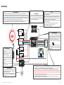
Assembly
IMU
GPS/COMPASS
·
·
·
·
·
GPS/Compass is sensitive to magnetic interference, should be far away from any electronic devices.
You should use epoxy resin AB glue to assemble the GPS bracket first as the figure showed in previous page.
Mount the bracket on the center plate of craft first, then fix the GPS on the plate of the bracket (by 3M glue
provided). The GPS is sensitive to vibration interference, so position the bracket at least 10 cm from any rotor.
The DJI logo marked on the GPS should face the sky, with the orientation arrow pointing directly forward. The
GPS/Compass is packaged with a special indication line for mounting for the first time.
If you are uncertain whether materials near the GPS/Compass module are magnetic or not, you can use a
compass or magnet to check it. If you use your own mounting rod, make sure it is NOT magnetic!
·
R/C System
·
These are example connections. Please setup
Aileron, Elevator, Throttle, Rudder channels on your
Tx first, and choose one 2 or 3 positions switch/
channel as control mode switch, then connect your
receiver to the right ports on MC.
·
·
·
·
·
·
The IMU is best positioned near the multi rotor’s center of gravity, where
vibration is relatively low.
Orient the IMU such that the arrow marked on the printed surface of the
IMU faces the sky and points directly forward, backward, left or right.
The sides of the IMU should be precisely parallel to the multi rotor body.
Use double-sided foam tape for secured installation.
Check the double faced adhesive tape regularly to ensure that the IMU
is securely positioned.
DO NOT cover the ventilation holes, keep them unobstructed.
The IMU module is NOT water-proof or oil-proof.
Do not mount the IMU upside-down.
AUX2
R/C Receiver
(JR)
Main Controller
RUDD
ELEV
GEAR
AILE
AUX1
THRO
AUX2
R/C Receiver
(Futaba / Hitec)
·
M6
M5
M4
M3
M2
M1
M8
M7
1
2
3
4
7
Futaba
S-Bus/S-Bus2
·
·
·
·
·
There is no requirement for PMU
mounting.
Use our PMU Connecter (red line
depicts in figure) to connect
battery, PMU and ESCs.
For safety reason, please
disconnect ESCs and battery
connecter during the firmware
upgrade and configuration
procedure.
You can choose 2S-6S LiPo
battery.
Sufficient air flow over the PMU is
highly recommended.
Battery
PMU & Battery
LED Indicator
·
·
Place the LED indicator at an appropriate location of
craft body far away from the GPS. Do not mount it
on other electronic devices.
Make sure You can see the light during the flight.
You can connect LED to the CAN-Bus port on GPS
connection wire.
·
After choosing a location to mount the MC, it is
recommended that you DO NOT mount the MC
until all wirings and software configurations are
completed.
Roll
R/C Receiver
(PPM)
PPM
Pitch
F1
ESC & Motor
·
·
·
·
©2012 DJI Innovations. All Rights Reserved.
ESC
F2
S-Bus/S-Bus2
·
·
·
There is no orientation requirement for the Main
Controller. Choose a mounting location where
as shorter ESC extension wires are needed as
possible. Please make sure all ports are
accessible when installing the MC so as to
facilitate wiring and software configuration.
In three-pin ports, pins near the nicks are signal
pins.
Please make sure you are using the ESCs and motors recommended by the manufacturer of your multi rotor first. We
recommend you use DJI motors and ESCs. WKM output is 400Hz refresh frequency.
Connect all ESCs to MC by the motor numbering method introduced in Multi-Rotors Supported of Appendix.
If you use 3rd party ESCs, please make sure the ESCs travel midpoint is at 1520us. DO NOT use 700us travel
midpoint ESC, as it may lead aircraft to fly away or cause injury and damage. After connect ESCs, calibrate ESCs one
by one through the receiver directly before connect them to your MC, Make sure program all of them into Governor
off, Break off and Normal Start up to get best experience.
If you use 3rd party ESCs, please cut the red wire (power wire) of your ESCs , as the power from V-SEN on PMU is
suitable to most of receivers and other electronic devices.
If you use extra BEC, please use a servo cable without power wire to connect V-SEN to X1. (Not recommend)
9|
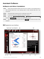
Assistant Software
Software and Driver Installation
STEP1:
Please download assistant software and driver from our website. If your operating system is
32bit, download 32bit driver; if your operating system is 64bit, download 64bit driver. Then
decompress;
STEP2:
Connect MC (Main Controller) and PC via USB cable, power on MC;
STEP3:
If operating system tries to install driver automatically, cancel it.
STEP4:
Open folder DJI_Wookong_M_Driver_32bit or DJI_Wookong_Multi_Rotor_Driver_64bit,
double click Driver Setup.bat file and follow the steps to finish installation.
STEP5:
Open the assistant software folder, double click Setup.exe file and follow the steps to finish
installation.
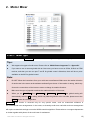
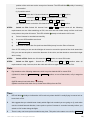
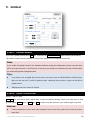
GUI (graphical user interface)
1
13 14
5
2
6
3
7
4
15
©2012 DJI Innovations. All Rights Reserved.
9
8
12
11
10
10 |
1
TOOL
Flight Limits: Set the height limit or distance limit if necessary, please refer to the section of “Flight
Limits” for details.
Firmware upgrade: Update your firmware from DJI server, keep your WKM system up-to-date.
Disable All Knob: Set remote gains in “Autopilot” menu to INH
Check for Updates: Check for latest versions of assistant software and firmware. If necessary,
you can follow the links displayed to find the download page.
2
ABOUT
Info: Information regarding your WKM.
Error Code : Error code list
3
中文: Chinese interface.
4
ENGLISH: English interface.
5
WRITE: Write data of the current page to your MC. The parameter or the title of which will turn red and
bold when modified, make sure you click the Write button or press Enter to update your system.
Optional parameters will be written to MC directly after modification.
6
READ: Read parameters from MC for current page.
7
EXPORT: Export configuration data.
8
IMPORT: Import version compatible configuration data.
9
Graphical guidance
10
Text guidance
11
CONTROL MODE: Control mode indication.
12
MC Output On: Indicates the outputs of the ESCs are enabled; when communication is established
between MC and assistant software via the USB cable, MC Output Off appears, it indicates no output
to the motors, and then you can safely configure your multi rotor with the assistant software.
13
Red light: WKMPC has been disconnected.
Green light: WKMPC is connected.
Blue light: WKMPC communication.
14
Configuration sub menus.
15
Configuration step.
Note:
Please power the MC first, then connect your MC to a internet enabled computer by the USB cable
before you open the assistant software. You have to register at the first time you use the assistant
software. It will auto detect the software version when you open the assistant software and will give
you a prompt message if your version is not the latest one.
Do not disconnect MC and PC when you are importing or exporting data. You can only import
version compatible configuration data.
©2012 DJI Innovations. All Rights Reserved.
11 |
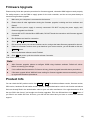
Firmware Upgrade
Please strictly follow the operation procedure for firmware upgrade, otherwise WKM might not work properly.
For safety reasons, use the PMU to supply power for the main controller, and do not use power battery to
motors during firmware upgrade.
1.
Make sure your computer is connected to the Internet.
2.
Please close all other applications during the firmware upgrade, including anti-virus software and
firewall.
3.
Make sure the power supply is securely connected. DO NOT un-plug the power supply until
firmware upgrade has finished.
4.
Connect MC to PC with the Micro-USB cable; DO NOT break the connection until firmware upgrade
is finished.
5.
Run Software and wait for connection.
6.
Select TOOLFirmware Upgrade.
7.
DJI server will check your current firmware version, and get the latest firmware prepared for the unit.
8.
If there is a firmware version more up-to-date than your current version, you will be able to click the
Upgrade button.
9.
Wait until Assistant software reads Finished.
10.
Click OK and power cycle the unit after at least 5 seconds.
Your unit is now up-to-date.
Note:
After firmware upgrade, please re-configure WKM using Assistant software. Default all values
before re-entering your settings.
If it is notified that the network or DJI server is busy, please try again later with above procedures.
If firmware upgrade failed, WKM will enter waiting for firmware upgrade status automatically, please
try again with the above procedures.
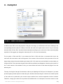
Product Info
You can check the MC product version via ABOUT Info. This includes software version, firmware version,
IMU version, hardware ID and loader version. S/N is a 32 digit authorization code for unit function activations.
We have already filled in the authorization code for your unit after manufacture. You might be asked to fill in
the new S/N in the future if you brought new function upgrades. Fill-in the S/N and then click Write button. If
you filled in an invalid S/N over 30 times, your MC will be locked and you have to contact our customer
support.
©2012 DJI Innovations. All Rights Reserved.
12 |
Configuration
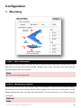
1. Mounting
STEP1: IMU Orientation
Select IMU mounting orientation. Orientate the IMU such that the arrow marked on the printed surface of the
IMU faces the sky and points directly forward, backward, left or right. The sides of the IMU should be
precisely parallel to the multi rotor body.
Note:
Do not mount the IMU upside-down.
STEP2: Mounting Location
Install all payloads that will be used during the flight, including batteries, camera mount and camera. Balance
the multi rotor as you would normally, with the center of gravity (C.G.) directly on the center plate. Fill in the
distance between the center of the IMU / GPS case and the C.G. of the multi rotor in X, Y & Z axis as showed
in the figure.
Notices:
Note:
©2012 DJI Innovations. All Rights Reserved.
13 |
1
You must re-measure and re-configure if the ALL-UP-WEIGHT of the multi rotor has changed.
2
If measured locations are not accurate enough or the signs (+/-) are wrong, then the error on the X,
Y,Z axis will lead to an oscillation of your multi rotor.
3
Make sure you follow the diagram in our assistant software: red is positive, green is negative; unit of
measurement is CM, NOT INCH…i.e. centimeters.
©2012 DJI Innovations. All Rights Reserved.
14 |
2. Motor Mixer
STEP1: Mixer Type
Set your transmitter into AEROPLANE mode. Then select the right mixer type according to your multi-rotor.
Tips:
We support nine types of multi-rotors. Please refer to “Multi-Rotors Supported” in “Appendix”:
If you want to use a camera gimbal with an Octo-rotor, you have to use an S-Bus, S-Bus2 or PPM
receiver, and then you can use port T and R for gimbal control. Otherwise, there will be no ports
available on the MC for gimbal control.
Note:
Do NOT follow the instructions from your multi-rotor manufacturer! Make sure the rotation direction
of each motor is the same as the assistant software figure shows. If the rotation is wrong, switch any
of two wire connections of the incorrect motor to change its rotation direction.
Make sure the type of propeller matches the rotation direction of the motor.
When you set Mixer Type from Octo-rotor to Quad-rotor / Hexa rotor, the gimbal setting will
automatically switch to off for safety, which may lead the gimbal to tilt to one side, please turn to the
Gimbal section for reconfiguration.
Customize: This section is reserved only for very special cases, such as customized airframes in
non-conventional rotor arrangements. In the event, an airworthy multi-rotor craft with such rotor arrangement
will require customized settings to meet the WKM controller algorithm. Please write to our support department
or dealer together with photos of the multi-rotor for assistance.
©2012 DJI Innovations. All Rights Reserved.
15 |
Tips:
Please refer to “Customize Motor Mixer” section in “Appendix” for how to customize a central
symmetry multi rotor.
If you customize the motor mixer of a quad-rotor or hexa-rotor, F1 and F2 ports can still be used for
gimbal servo control.
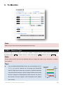
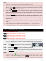
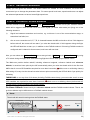
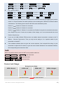
STEP2: Motor Idle Speed
Motor Idle Speed: is the lowest speed after motor start. Set Motor Idle Speed will affect the motor lowest
speed after motor start. There are five levels from LOW speed to HIGH speed, and the default is
RECOMMEND. You can click and drag the cursor
to the corresponding level, to change Motor Idle
Speed.
LOW
RECOMMEND
Lower motor idle speed
HIGH
Higher motor idle speed
Set Motor Idle Speed as LOW, the motor idle speed will be lowest.
Set Motor Idle Speed as HIGH, the motor idle speed will be highest.
RECOMMEND is the advised level.
You can reset the Motor Idle Speed according to the real situation.
Note:
For users whose aircraft takes off at a low throttle position, please set the idle speed at a low level.
For common users, please set Motor Idle Speed to RECOMMEND or above, since setting idle
speed too low may affect the motor(s) spool up.
Tips:
The output pulse width for every point of Motor Idle Speed is as follows
LOW
output pulse width
1144 us
RECOMMEND
1160 us
1176 us
HIGH
1192 us
1208 us
There is a relationship between the output pulse width and the max/min pulse width when the TX
End Point is 100%.
output pulse width=(max pulse-min pulse) x proportion + min pulse
You can get the proportion value by calculating according to the above formula for a special TX. Use
Futaba TX for example. Notice that Futaba TX End Point is 100%.
LOW
proportion value
3%
©2012 DJI Innovations. All Rights Reserved.
RECOMMEND
5
7%
HIGH
9%
11%
16 |
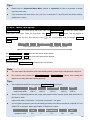
3. Tx Monitor
Note:
Make sure you have removed all propellers before this step!
STEP1: Receiver Type
Choose the type of your receiver. If you use an S-Bus or S-Bus2 receiver, please choose S-Bus/S-Bus2
compatible option: D-Bus. If a PPM receiver is used, please choose PPM. Otherwise choose Tradition.
Note:
Please reboot the MC and redo the calibration after you change the setup of your transmitter or change
your receiver!
Tips:
If you use S-Bus/S-Bus2/PPM receiver, the communication of A, E,
T, R, U, X2 and X3 channels are all through the D-Bus/PPM
channel. Right figure shows the connection of default transmitter
channels and MC channels in S-Bus/ S-Bus2/ PPM receivers (Only
the first 8 channels of S-Bus/S-Bus2/ PPM receivers are used at
the moment). Then the original T and R channels are for Gimbal
Transmitter
Channels
1
2
3
4
5
6
7
MC
Channels
A
E
T
R
U
X2
X3
servo control.
©2012 DJI Innovations. All Rights Reserved.
17 |
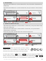
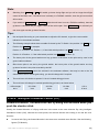
STEP2: Cut Off Type
Please read the introductions of start and stop motor in this step first, and then choose a cut off type.
1
Start Motor: When using WKM, pushing the throttle stick before takeoff will not start the motors. You
have to execute any one of following four Combination Stick Commands (CSC) to start the motors:
2
Stop Motor: We provide two options to stop motors: Immediately, or Intelligent.
Immediately Mode: By using this mode, in any control mode, once the motors start and the
throttle stick is above 10%, the motors will stop immediately when the throttle stick is back
below 10% again. In this case, if you push the throttle stick above 10% within 5 seconds after
the motors stop, then the motors will re-start, CSC is not needed. If you don’t increase the
throttle stick within 3 seconds of the motors starting, then the motors will stop automatically.
Intelligent Mode: By using this mode, different control modes have a different way of
stopping the motors. In Manual Mode, only executing CSC can stop the motors. In Atti. or
GPS Atti. Mode, any one of the following four cases will stop the motors:
a)
If you don’t increase the throttle stick within 3 seconds of the motors starting
b)
Executing CSC
c)
Throttle stick under 10%, and after landing for 3 seconds.
d)
The angle of the multi-rotor is over 70°, and throttle stick under 10%.
Tips (Intelligent Mode):
1
You have to execute CSC to start the motors. “Only” raising the throttle stick will not start the
motors.
2
In Atti. / GPS Atti. Mode, it has landing judgment, which will stop the motors.
3
Start motors in Atti. / GPS Atti. Mode, you have to execute CSC and then push throttle stick over
10% within 3 seconds, otherwise motors will stop after 3 seconds.
4
During normal flight, only lowering the throttle stick under 10% will not stop the motors in any control
mode.
5
For safety reasons, when the slope angle of the multi-rotor is over 70°during the flight in Atti. / GPS
Atti. Mode (may be caused by collision/crash, motor and ESC error or propeller broken), and throttle
stick is under 10%, the motors will stop automatically.
6
You can stop the motors by executing CSC in any control mode.
©2012 DJI Innovations. All Rights Reserved.
18 |
Note:
1.
The two cut off types will only work correctly if the Tx calibration is correct.
2.
When Tx commands are valid under any control modes, the motors will start or stop immediately
when you execute CSC. It has nothing to do with the current throttle stick position. Please DO NOT
executes CSC during flight without a good reason.
3.
If you choose Immediately mode, you should not lower the throttle stick under 10% during
flight, because this will stop the motors. If you do it accidentally, you should push the throttle
stick above 10% within 5 seconds to re-start the motors.
4.
If you choose Intelligent mode, throttle stick below 10% will trigger landing judgment in any control
mode. In this judgment, pitch, roll and yaw controls are disabled except throttle, but the multi-rotor
will still auto level.
5.
In any control mode, DO NOT lower the throttle stick below 10% during normal flight without a good
reason.
In any auto action caused by FailSafe or low voltage protection (e.g. auto Go Home),any
6.
commands applied to start or stop the motors are denied by the MC, motors will auto control.
STEP3: Command Sticks Calibration
On screen Slider Definition:
T
: Slider left is craft down, slider right is craft up
R
: Slider left is nose left, slider right is nose right
E
: Slider left is craft back, slider right is craft front
A
: Slider left is craft left, slider right is craft right
STEP1:
Set endpoints of all channels to default values (100%) and set all trims and sub-trims of sticks
to 0 on your transmitter first. Keep all curves’ settings as default since the end-point of transmitter
sticks will be recorded here.
STEP2:
Click START button, and move all of the sticks throughout
their complete range several times.
STEP3:
After that, click FINISH button when you finished above procedures.
STEP4:
If the moving direction of the slide is opposite to the Slides Moving Definition, click the reverse
button REV/NORM at the right side of the screen.
Note:
1.
All sliders should become
when all the Tx sticks are in the middle positions. If the sliders cannot
go back to center points (become ), just click FINISH, then the sliders will be at center
automatically. If still not centered, please reboot the MC, and do not apply any Tx command during
©2012 DJI Innovations. All Rights Reserved.
19 |
the reboot.
2.
CSC may not start motors If trims and sub-trims of Tx sticks are not 0!
STEP4: Sticks Monitor
This step is optional. X2 and X3 is for remote gain tuning; X3 is also for gimbal pitch control. Setup the
channel on your RC correctly.
STEP5: Control Mode Switch
Whichever 2 or 3 position switch on your transmitter you have selected to use as control mode switch,
connect the correct channel of the receiver to the U port of the MC. At each switch position, use end-point fine
tuning on your transmitter. Move the Transmitter slider/switch of the channel U to GPS (GPS Atti Mode), A
(Atti. Mode), M (Manual Mode) and adjust the Tx end-points and mid-point to turn the corresponding area on
the assistant software blue shown at the bottom of the TX MONITOR screen.
Tips:
To move the slider is to adjust end-points of the channel selected.
For
3-position switch,
you should assign:
Position-1 to Manual Mode; Position-2 to Atti.
Mode; Position-3 to GPS Atti. Mode; or reverse
3 Position
Switch
1
2
3
Tx
the assignment for Position-1 and Position-3.
For 2-position switch, you can assign any two of the three control modes as you like.
Important: You must setup the FailSafe of your Transmitter so during a FailSafe situation the area which
reads FailSafe Mode turns blue. Once FailSafe is setup, if you switch off your transmitter, the U channel
slider should move to FailSafe Mode and turn the corresponding area to blue. Otherwise please reset the
FailSafe. Please refer to your RC manual for the details of FailSafe setup.
Note:
Do NOT set the FailSafe position of the throttle below 10% endpoint.
MC will not execute the FailSafe protection if you don’t set it properly. You can verify the
FailSafe settings by switching off your transmitter, and then you can use the following
methods to check whether the MC is in FailSafe mode.
Check the Assistant Software status bar at the bottom of the software interface.
Control mode will change to FailSafe.
Check the LED indicator. Read the appendix in this manual for details. LED will give blue
blinking if in FailSafe mode.
©2012 DJI Innovations. All Rights Reserved.
20 |
4. Autopilot
STEP1: Basic Parameters
Usually, the default parameters are ready to go. However, different multi rotors have different gains because
of different size, ESC, motor and propeller. If the gain is too large, you will find the multi rotor oscillating in the
corresponding direction (About 5~10Hz). If too small, the multi rotor maybe hard to control. So you can setup
the basic Gain of Pitch, Roll, Yaw and Vertical manually according to your multi rotor to have a pleasing flight
experience. We suggest you change the values by 10% to 15% at a time and test fly.
For the gains of Pitch and Roll, if you release the Pitch or Roll stick after a command stick input, the
multi-rotor will revert back to the hovering state. If the reaction of the multi-rotor in this procedure is too soft
(large delay), please increase the basic gain slowly (10%-15% each time) until oscillation is noticed after you
release the stick. Then decrease the gain a little until the oscillation just disappears. Now the gain is perfect. If
the Tx stick reaction of the attitude is slow, you should follow the section a little down the page to tune the
attitude gains.
The way of tuning the Yaw gain is the same as the way of adjusting the Tail Gyro of a helicopter. If you want
quicker stopping reaction speed, increase the gain, otherwise decrease the gain. However, the rotation speed
of the multi-rotor is produced by the counter torque reaction force, and the magnitude of which is limited.
Therefore, a large gain value will not produce tail oscillation like on a helicopter, but severe reaction of the
©2012 DJI Innovations. All Rights Reserved.
21 |
start or stop of the motors, which will affect the stabilization of other axis.
You can use two methods to judge if the Vertical gain is good enough: 1) The multi-rotor can lock the altitude
when the throttle stick is at the center position; 2) The change of altitude is small during the flight along a
route. You can increase the gain slowly (10% each time) until an oscillation in the vertical direction appears or
the reaction of the throttle stick is too sensitive, then decrease 20% of the gain. Now you should have a
suitable Vertical gain.
Attitude gains determine the reaction speed of attitude from a Tx command stick input. The bigger the value
the quicker the reaction from the Tx command. Also, an increased value will also give a sharper and quicker
leveling action after the command stick is released. The control feeling will be stiff and rigid if the value is too
high; and sluggish leveling action and slow braking if too small.
Note:
You MUST click the Default button before configuring the gains for the first time, and also after a
firmware upgrade, before re-entering your settings.
The vertical gain has no effect in manual mode.
Tips:
If you are a new user to this system, you can tune the basic parameters first as follows:
1
Increase the basic parameters 10% at a time so as to make your multi rotor hover or lightly
oscillate after small angular command inputs.
2
Decrease the basic parameters until your multi rotor can just hover without oscillation, then
decrease 10% more.
If the basic parameters are far away from the required values, the advanced parameters will not
work.
You can use the remote gain-tuning channels to tune the gains during the flight:
1
Follow the instructions in “Assembly” R/C System section to connect and setup correctly;
2
Choose the X2 or X3 channels in Remote Adjust for the gain you want to tune. One channel to
one gain.
3
The range of the remote tuning is from half of the current entered value to twice current value.
Usually the Pitch, Roll, Attitude Pitch and Attitude Roll Gains of a hexa-rotor are higher than a
quad-rotor.
You will find example settings at the end of this manual
©2012 DJI Innovations. All Rights Reserved.
22 |
STEP2: Advanced Parameters
Usually you can ignore this section. The default values are suitable for most conditions, so we do NOT
recommend you to change the parameters here. For some special multi rotor, experienced users can adjust
the advanced parameters to have a better flight experience.
STEP3: Enhanced FailSafe Methods
FailSafe methods include Hover, Go-home, and Altitude Go-home. Choose one as your FailSafe method,
which will be triggered when the MC loses the control signal (no matter what mode you flying) one of the
following situations:
1)
Signal lost between transmitter and receiver, e.g. multi-rotor is out of the communication range, or
transmitter has failed, etc.
2)
One or more connections of A, E, T, R, U channels between the MC and receiver is lost. If this happens
before take-off, the motors will not start if you raise the throttle stick. If this happens during the flight,
the LED will flash blue to warn you, in addition to the FailSafe method. If Hovering FailSafe method is
configured and U channel is disconnected, multi-rotor will auto land.
Also, you can select the Go-Home Switch item to start go-home (Go-home, and Altitude Go-home) by using
a TX switch during the flight, when selected during flight the LED will flash purple instead of blue.
The Multi-rotor position before takeoff, including reference longitude, reference latitude and reference
altitude, is saved as home point by the MC automatically when you raise the throttle stick for the first time
AND it has 6 or more GPS satellites acquired for more than 8 seconds (
blinks once or no blinking >8secs)
After taking off, every time the aircraft recorded a home-point successfully the LED will blink Cyan quickly for
indicating.
THEREFORE: to use any form of Go-home (including FailSafe return home), you must make sure 6 or more
GPS satellites are acquired for more than 8 seconds (
blinks once or no blinking >8secs) before take-off,
this will assure correct recording of the Home position.
Go-Home Altitude: Determined by the reference altitude and the FailSafe method chosen. That is, the
go-home altitude may be different due to FailSafe method chosen.
Hover
The aircraft will remain hovering when the FailSafe starts.
Home Location
(Reference longitude, latitude, altitude )
If GPS satellite found >= 6 and last 8s,
at the first time you pull the throttle
stick, then record Home Location
1 Record
Aircraft
Stay hover
Signal lost
Tx
2 Flight
Tx
3 Hover
Fail-safe
©2012 DJI Innovations. All Rights Reserved.
23 |
Go-H (Go-home)
Flight altitude when FailSafe starts > (reference altitude+20m),then go-home altitude=flight altitude when
FailSafe starts
Flight altitude when FailSafe starts <= (reference altitude+20m),then go-home altitude=reference altitude
+20m
Home Location
(Reference longitude, latitude, altitude )
If GPS satellite found >= 6 and last 8s,
at the first time you pull the throttle
stick, then record Home Location
1 Record
Stay hover
Signal lost
Tx
Tx
2 Flight
3 Hover
Flight altitude when fail-safe starts
>(reference altitude+20m)
Ready to
Go-Home
Tx
Flight altitude when fail-safe starts
<=(reference altitude+20m)
Tx
4 Ready to go home
Aircraft
Home
Hover 15s ,
Then land.
20m
Signal lost > 3s
Fail-safe/Enable Go-Home Switch
Tx
6 Land
5 Go home
Go home
Altitude Go-H (Altitude Go-home)
Flight altitude when FailSafe starts > (reference altitude + entered value),then go-home altitude=flight
altitude when FailSafe starts.
Flight altitude when FailSafe starts <= (reference altitude + entered value),then go-home altitude=
reference altitude + entered value.
Entered value: 20m~300m, the default value is 20m, and has an accuracy of 1m.
Home Location
(Reference longitude, latitude, altitude )
If GPS satellite found >= 6 and last 8s,
at the first time you pull the throttle
stick, then record Home Location
1 Record
Stay hover
Tx
4 Ready to go home
Aircraft
Home
3 Hover
Flight altitude when fail-safe starts
>(reference altitude+ input value)
Ready to
Go-Home
Tx
Tx
2 Flight
Signal lost > 3s
Signal lost
Input value
Tx
Hover 15s ,
Then land.
Flight altitude when fail-safe starts
<=(reference altitude+ input value)
5 Go home
Fail-safe/Enable Go-Home Switch
Tx
6 Land
Input value
Go home
Go-Home Switch: Before using this function, you have to choose a
2-Position
2-position switch on your transmitter as the Go-Home switch. Then
1
2
Tx
connect the correct channel of the receiver to the X3 port of the MC.
You should assign: Position-1 to Start; Position-2 to Standby; or reverse the assignment for Position-1 and
Position-2. Move the Tx switch of the channel X3 and check that the corresponding area Start and Standby
turns blue on the assistant software screen. If required adjust the Tx channel end points.
©2012 DJI Innovations. All Rights Reserved.
24 |
Note:
Switching from Standby to Start will enable go-home during flight and you will no longer have flight
control of the Multi rotor. If the Multi rotor is already in a FailSafe condition, then the go-home switch
will not work.
If you switch to Manual Mode or Atti. Mode, (and the multi rotor is not in a FailSafe condition), then the
go-home is cancelled and you regain control of the multi copter. Once GPS. Mode is re-selected you
can once again use the go-home function.
Tips:
Use end-point fine tuning on your transmitter to adjust the X3 channel, to give the correct switch
indication in the assistant software.
The following example shows how to enable Go-home by the Tx Switch. Use position-1 to Start and
Position-2 to Standby for example.
Position -1 Position -2 Position -1, if the initial switch position is at Start (Position -1).
Position -2 Position -1, if the initial switch position is at Standby (Position -2).
The home point of the ground station one key go-home is the same as the point set by user in the
ground station software.
If the home point is not set by the ground station, the home point of the ground station one key
go-home function is the point recorded by the MC.
If the Go-Home Switch cannot be selected in the assistant software, that may be due to the X3
channel been set for remote gain tuning, you should change this if required.
The multi rotor will climb at a speed of 1.5m/s if needed during go-home.
The multi rotor will change its vertical speed during go-home, as shown below:
>100m height
50~100m
20~50m
10~20m
<10 m
4m/s
3m/s
2m/s
1m/s
0.3m/s
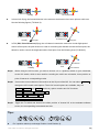
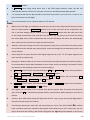
STEP4: Intelligent Orientation Control (IOC)
Forward Direction: The Multi-rotor will fly along this direction when you
push the elevator stick.
Usually, the forward direction of a flying multi-rotor is the same as the nose direction. By using Intelligent
Orientation Control (IOC), wherever the nose points, the forward direction has nothing to do with the nose
direction:
In course lock flying, the forward direction is the same as a recorded nose direction. See the following
figures (TX Mode 2):
©2012 DJI Innovations. All Rights Reserved.
25 |
Usually
In course lock
In home lock flying, the forward direction is the same as the direction from home point to multi-rotor.
See the following figures (TX Mode 2):
In home lock
Usually
Home point
Home point
In POI (POI, Point Of Interest) flying, the roll channel controls the multi rotor circular flight speed
around a fixed point, the pitch channel is used for controlling the diameter around the fixed point, the
throttle is used to control the height around the fixed point. See the following chart (Tx Mode 2):
Semi-diameter
POI
Usually
Step1:
Point of Interest
Before using the IOC function, you have to choose a 2 or 3 positions switch on your transmitter
as the IOC switch, which is also used for recording the multi rotor orientation, home position or
point of interest in corresponding modes.
Step2:
Connect the correct channel of the receiver to the X2 port of the MC. You can select Control 1 to
change the IOC control mode options. Three IOC control options are available; they are
Control 1, Control 2 and Control 3, and every option contains two IOC functions.
Control 1: Home Lock, Course Lock, OFF
Control 2: POI, Course Lock, OFF
Control 3: Home Lock, POI, OFF
Step3:
Toggle the Tx switch and observe the slider position of channel X2 on the assistant software
screen, the corresponding area should turn blue.
Tips:
3 Position
Switch
1
2
Tx
3
2-Position
1
2
Tx
For 3-position switch (or exchange Position-1 and Position-3):
©2012 DJI Innovations. All Rights Reserved.
26 |
Control 1: Position-1 is OFF; Position-2 is Course Lock; Position-3 is Home Lock.
Control 2: Position-1 is OFF; Position-2 is Course Lock; Position-3 is POI.
Control 3: Position-1 is OFF; Position-2 is POI; Position-3 is Home Lock.
For 2-position switch:
Control 1: Position -1 is OFF; Position-2 is Course Lock. Or Position -1 is OFF; Position-2 is Home Lock .
Control 2: Position -1 is OFF; Position-2 is Course Lock. Or Position -1 is OFF; Position-2 is POI .
Control 3: Position -1 is OFF; Position-2 is POI . Or Position -1 is OFF; Position-2 is Home Lock.
The course, home point and point of interest can be recorded manually by toggling the 3-position
switch 3 to 5 times between two switch positions, the recorded point is different for different switch
combinations. The following shows how the MC will record the different points.
Position-1
Position-2: Position-2 is recorded.
Position-2
Position-3: Position-3 is recorded.
Position-1
Position-3: Position-3 is recorded, but Position-2 may also be recorded at the same
time. Danger may occur if users are not aware of the change, so it is not recommended to record
Position-3 by this way.
If you use an S-Bus /S-Bus2 /PPM receiver, the default channel connection is shown in the Tx
Monitor – Receiver Type section. Then you only need to assign a 2 or 3-position switch of your
transmitter to channel 5.
If the assistant software does not give the correct response, Use end-point fine tuning on your
transmitter to adjust the X2 channel, to give the correct switch indication in the assistant software,
the corresponding area should turn blue.
NotE:
When a 2-position switch is used, do NOT set a 2-position switch as:
Control 1 : Course Lock and Home Lock at the same time.
Control 2 : Course Lock and POI at the same time.
Control 3 : POI and Home Lock at the same time.
Course Lock Usage:
During the same flight:
STEP1: Record
STEP2: ON
Nose direction;
©2012 DJI Innovations. All Rights Reserved.
STEP3: OFF
STEP4: ON again
Forward direction
27 |
STEP1:
Record forward direction: There are two ways: Manually and Automatically. The LED will
blink
a)
quickly if recording is successful.
Automatically: The MC will record the current nose direction as forward direction, 30 seconds
after you power on the multi-rotor. **PLEASE BE AWARE OF THE FORWARD DIRECTION
WHEN YOU SWITCH ON THE MULTI ROTOR IF YOU USE COURSE LOCK**
b)
Manually: You can switch the X2 channel between OFF and Course Lock position quickly 3
to 5 times to record the current nose direction as the new forward flight direction at any time
after you power on the multi-rotor for longer than 30 seconds.
STEP2:
Switch on course lock: Switch the X2 channel from OFF to Course Lock position, when all
the following requirements are met the LED will blink
a)
The forward direction is recorded successfully
b)
The MC is in Atti. or GPS Atti. Mode
slowly to indicate the IOC mode.
STEP3:
Switch off course lock: Switch the X2 channel to OFF position to quit course lock.
STEP4:
Switch on course lock again: When all requirements in step 2 are met, Switch the X2
channel from OFF to Course Lock position.
Note:
Pay attention to the following statement, which may also lead the MC to cancel the course lock:
Switch U channel to Manual Mode position, or switch off transmitter, or fly in waypoint mode.
Home Lock Usage:
During the same flight:
STEP1: Record
Nose direction;
STEP 1:
STEP2: ON
Forward direction;
STEP3: OFF
Home point;
STEP4: ON again
Over 10m distance
Record home point: The home point mentioned here is the same home point as the enhanced
FailSafe. There are two ways to record this point: Manually and Automatically. The LED will blink
quickly
if recording is successful.
a)
Automatically: Before takeoff, the current position of the multi-rotor will be saved as the home
point by the MC automatically when you raise the throttle stick for the first time AND it has 6 or
b)
more GPS satellites acquired for more than 8 seconds (
blinks once or no blinking >8secs)
Manually: When 6 or more GPS satellites are found (
blinks once or no blinking), you can
©2012 DJI Innovations. All Rights Reserved.
28 |
switch the X2 channel between two positions quickly 3 to 5 times to record the current position
of the multi-rotor as the new home point.
(1) 3-position switch:
Control 1: switch the X2 channel between Course Lock and Home Lock position,
or OFF and Home Lock (NOT Recommended);
Control 3: POI and Home Lock, or OFF and Home Lock (NOT Recommended).
(2) 2-position switch: switch the X2 channel between OFF and Home Lock position.
STEP 2:
Switch on home lock: Switch the X2 channel from OFF to Home Lock position when all the
following requirements are met. The LED will blink
slowly to indicate the IOC mode.
a)
Home point is recorded successfully
b)
6 or more GPS satellites are found
c)
In GPS Atti. Mode;
d)
Multi-rotor is further than 10m away from the home point.
STEP 3:
Switch off home lock: Switch the X2 channel to OFF position to cancel home lock.
Step 4:
Switch on home lock again: When all requirements in the second step are met, switch X2
channel from OFF to Home Lock position to enter home lock mode again.
Note:
Pay attention to the following statement, which may also lead the MC to cancel home lock:
Switch U channel to Manual Mode or Atti. Mode position, or turn off transmitter, or fly in waypoint
mode.
If you select Atti. Mode during home lock flight, then course lock is set using the current (not
recorded) forward flight direction.
POI (Point Of Interest) Usage:
During the same flight:
STEP1: Record
Nose direction;
STEP1:
a)
STEP2: ON
Forward direction;
STEP3: OFF
Point of interest;
STEP4: ON again
Semi-diameter
Record point of interest:
Manually: When 6 or more GPS satellites are found (
blinks once or no blinking), you can
switch the X2 channel between two positions quickly 3 to 5 times to record the current
©2012 DJI Innovations. All Rights Reserved.
29 |
position of the multi-rotor as the new point of interest. The LED will blink
quickly if recording
is successful.
(1) 3-position switch:
Control 2: switch the X2 channel between Course Lock and POI position,
or between OFF and POI position (NOT Recommended);
Control 3: switch the X2 channel between OFF and POI position.
(2) 2-position switch: switch the X2 channel between OFF and POI position.
STEP2:
Switch on POI: Switch X2 channel from OFF to POI position when all the following
requirements are met. After switching on POI, the multi rotor will rotate slowly until the multi rotor
nose points to the point of interest. The LED will blink
slowly to indicate the IOC mode.
a)
Point of interest is recorded successfully
b)
6 or more GPS satellites are found
c)
In GPS Atti. Mode
d)
Multi-rotor is further than 5m (and less than 500m) away from the Point of Interest.
Once in POI mode you can use the left/right roll control to control the speed of the circle around the
POI, you can use the pitch to control the diameter of the circle, and the throttle to control the height
while circling.
STEP3:
Switch off POI: Switch the X2 channel to OFF position to cancel POI mode.
STEP4:
Switch on POI again : Switch the X2 channel from OFF to POI position when all
requirements in step 2 are met, then the multi rotor will once again turn towards the POI.
Note:
Pay attention to the following statement, which may also lead the MC to cancel POI:
(1)Switch U channel to Manual Mode or Atti. Mode position, or turn off transmitter, or fly in waypoint
mode.
(2)GPS status is bad, with three
blinking.
(3)Multi-rotor flies back within 5m (or further than 500m) from the POI.
Tips:
1
LED will blink
slowly to indicate the IOC mode only when the MC is really flying in course lock or
home lock or POI.
2
We suggest that you should know clearly which flight lock method you are going to fly, and make
sure the locked forward direction, home point or point of interest is recorded correctly before you
switch on IOC mode during the flight.
3
There is only one home point recorded at any time. This point is the same one used by Go-Home
©2012 DJI Innovations. All Rights Reserved.
30 |
and Landing FailSafe.
4
In Control 1, when flying using home lock, if the GPS signal becomes weak, the MC will
automatically switch to course lock using the current (not recorded) forward flight direction.
5
It is recommended that the pilot should be near the home point to use home lock, or near to the
point of interest to use POI flight.
6
It is recommended to use a 3-position switch for X2 channel.
Note:
1
Before home lock flight, you’d better fly the multi-rotor out of the 10m range around home point, then
slide X2 channel switch to Home Lock position to fly in home lock when all the requirements are
met. If you have already slide X2 channel switch to Home Lock position when the multi-rotor is still
in 10m range around home point, and this is the first time you are going to fly in home lock during
the current flight, then if all the requirements are met, MC will change into home lock automatically
when multi-rotor flies out the 10m range around home point.
2
When the multi-rotor is flying in home lock at a distance away from you and the home point, please
do not switch the X2 channel many times quickly, as this will change the recorded home point to the
current location.
3
Avoid using POI in areas where the GPS signal might be lost or the TX / RX signal might be lost
(such as built up urban areas)
4
By using a 3-position switch, if you want to record a new home point and point of interest manually, it
is recommended to record them separately so as to make sure the recording is successful. Please
pay attention to the following contents for correct recording.
Control 1: DO NOT switch X2 channel between OFF and Home Lock position, but only between
OFF and Course Lock, or Course Lock and Home Lock position.
Control 2: DO NOT switch X2 channel between OFF and POI position, but only between OFF
and Course Lock, or Course Lock and POI position.
Control 3: DO NOT switch X2 channel between OFF and Home Lock position, but only between
OFF and POI, or Home Lock and POI position.
5
We suggest you use home lock in a limited area which is greater than 10m away from the home
point; and use POI in a limited area greater than 5m (and less than 500m) away from the Point of
Interest
6
If there is poor GPS quality during the flight, then the M.C. may not give an accurate flight path for
the radius around the point of interest.
7
Continuously spinning the multi rotor will accumulate yaw errors. The LED will blink
to indicate
huge cumulative yaw errors caused by spinning the craft continuously in IOC. In this case, you can
stop or slow down the spinning, and continue flying after the
©2012 DJI Innovations. All Rights Reserved.
blinking has stopped, so as to have
31 |
better flight performance.
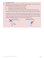
8
When flying in Home Lock mode, if any of the following situations happen, then the system will quit
Home Lock flying and automatically enter Course Lock flying.
The aircraft fly’s within 10m range of the home point.
You toggle the control mode switch to the ATTI. Mode.
The GPS signal becomes bad (The GPS signal LED is blinking Red twice or three times).
Important, in the Course Lock flying we mentioned above, if the IOC switch is still at the HL position,
the system will use a new forward direction (Example, Fig1) recorded at the moment, which is
pointing from the home point to the aircraft when changing from Home Lock to Course Lock flying.
However, if you toggle the IOC switch to the Course Lock, the aircraft will fly in Course Lock using a
different forward direction, which was recorded previously (Example, Fig2).
new forward direction
(related with the home point)
previous forward direction
(nothing with the home point)
Home Point
Fig.1
©2012 DJI Innovations. All Rights Reserved.
Fig.2
32 |
5. Gimbal
STEP1: Gimbal Switch
If you use a gimbal, please select On here, and select an Output Frequency (50Hz/100Hz/200Hz/400Hz).
The chosen output frequency should not exceed the maximum servo supported frequency.
Note:
If you enable the gimbal control in the assistant software during the configuration, please note that there
will be an output from the F1 and F2 ports. In this case you should not connect these ports to ESCs which
are wired with propeller equipped motors.
Tips:
If you want to use a gimbal with an Octo-rotor, you have to use an S-Bus/S-Bus2 or PPM receiver,
then you can use port T and R for gimbal control. Otherwise, there will be no ports on the MC for
gimbal control.
WKM supports servo center of 1520us.
STEP2: Servo Travel Limit
Range: -1000 to+1000.
MAX/MIN are servo travel limits; adjust them to avoid mechanical binding; Place your multi rotor on level
ground, adjust Center value of Pitch and Roll direction to set the camera to your desired angle-to-ground.
Notices:
If servo expansion is used, which may enlarge the servo travel limit, make sure to reset your servo
travel limit.
©2012 DJI Innovations. All Rights Reserved.
33 |
STEP3: Automatic Control Gain
Range: 0 to 100.
Adjust the reaction angle of automatic control. The initial value 100 is full angle. The bigger the gain, the
bigger the reaction angle. Click REV/NORM, and then you can reverse the feedback control directions.
STEP4: Manual Control Speed
Range: 0 to 100.
You should assign one of the knobs on your transmitter to the X3 channel for controlling the Pitch direction
(angle) of the camera gimbal during flight. Then adjust the reaction speed of the pitch direction manual
control; the initial value 100 is full speed.
When X3 is set as remote gain or for switch “go-home”, users can not adjust the gimbal pitch using the X3
channel, while WKM still provides enhanced stability for the gimbal; the gimbal pitch and roll will return to the
center position.
Note:
If the X3 channel is used for controlling the Pitch of the gimbal, then the X3 cannot be used for
remote gain tuning or Go-Home switch.
©2012 DJI Innovations. All Rights Reserved.
34 |
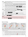
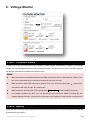
6. Voltage Monitor
STEP1: Protection Switch
In order to prevent your multi-rotor from crashing or other harmful consequences caused by low battery
voltage, we have designed two levels of low voltage protection. You can choose to not to use them, however
we strongly recommend to enable the protection here!
Note:
Make sure the two connections between the PMU and the MC (PW to CAN interface, V-SEN to X1)
are correct; otherwise the low voltage protection will not work correctly.
Both protections have LED warning as default. First level will blink yellow light
second level will blink red light
continuously;
continuously.
Both protections will only have LED warning under Manual Mode, NO AUTOMATIC functions.
Low voltage conditions are NOT fun! You should land your multi-rotor ASAP on seeing any low
voltage warning indication, to prevent your multi-rotor from crashing or other harmful consequences!
STEP2: Battery
Power the MC using your normal flight battery and connect the MC with a PC, the current battery voltage will
be displayed in this column.
©2012 DJI Innovations. All Rights Reserved.
35 |
If the battery voltage displayed here is different from the voltage you measure using
a voltmeter, you have to calibrate. Click the Calibration, enter the voltage you have
just measured in the Calibration column of the dialogue box, and then click OK.
Meanwhile you need to select the battery type you are using, so that the MC can provide default warning
voltages and ranges of warning voltages for you.
STEP3: First Level Protection
No Load (No Load Voltage): No load warning voltage. You need to enter this value.
Loss (Line Loss Voltage): The battery voltage drop during the flight. You need to enter this value.
Loaded (Loaded Voltage): The real-time battery voltage during the flight. This is the actual warning voltage
monitored by the MC. Does not require your input, calculated by No Load and Loss.
Tips:
Voltage Magnitude Relation:
No Load: First level > Second level.
Loss: First level = Second level.
Loaded: Calculated, First level > Second level.
Method of Acquiring Line Loss Voltage:
1
Make sure you can fly your multi-rotor normally with a fully charged battery.
2
Use a fully charged battery, switch on the low voltage protections in assistant software, and observe
the current voltage. Enter a reasonable warning voltage in the No Load of first protection (We
recommend to enter a voltage 1V lower than the current voltage and higher than the minimum
battery voltage rating). Enter 0V for the Loss at the moment.
3
Fly the multi-rotor until the first level protection is triggered, and the LED is flashing yellow. Now land
your multi-rotor ASAP.
4
Connect the MC to PC, open the assistant software and read the current voltage. The Loss (Line
loss voltage) is the difference between the new current voltage and the first level No Load voltage
you filled in.
©2012 DJI Innovations. All Rights Reserved.
36 |
Note:
If the line loss voltage of a battery is over 0.3V per cell (e.g. 3S battery over 0.9V), it’s because the
internal resistance of the battery is high or the battery is old, we suggest you replace it!
Generally the line loss voltage of different batteries is different. For the consideration of safety, we
recommend that you acquire all the line loss voltages of all the batteries you intend to use, and enter
the lowest value for the Loss.
When you change the payload or multi-rotor, you have to obtain the new line loss voltage.
The line loss voltage will be higher after many flights; you should obtain a new value after charging
30 times.
Make sure your ESCs protection voltage is lower than 3.1V (1S), otherwise the WKM low voltage
protection will not work.
1
Acquire the line loss voltage by the method above, and enter the value.
2
Enter a reasonable warning voltage in the No Load.
3
Choose a safeguard method: 1) LED warning: This is the default safeguard when you switch on the low
voltage protection; 2) Go Home and Landing: This safeguard will NOT be triggered if any of the
following conditions are true:
a)
Manual or Atti. Mode;
b)
GPS signal is not good;
c)
The distance between the Home Location and multi-rotor is less than 25m, and the altitude is
lower than 20m relative to the Home Location. Here the recorded Home Location is the same as
the one used for Enhanced FailSafe. Please refer to Enhanced FailSafe in “Autopilot”.
Note:
There will be a 4 second LED warning before Go Home.
If you switch to Manual or Atti. Mode during Go Home, you will regain the control. LED warning will
be still on, please land ASAP.
If you switch back into the GPS Mode when you are in first level protection, you will have 15s time to
control your multi-rotor, you should land ASAP in this 15s to prevent your multi-rotor from crashing
or other harmful consequences! After this time if the Go Home and landing requirements are
satisfied, the multi-rotor will Go Home and Land automatically.
If you choose LED warning, please land ASAP after you see the LED warning to prevent your
multi-rotor from crashing or other harmful consequences!
Compare the Go Home and Landing of low voltage protection and the Go Home and Landing in
Enhanced Failed-safe, the recording of the Home Location are the same; the Go Home routes are
the same; the difference is that there is no hovering before landing in low voltage protection.
©2012 DJI Innovations. All Rights Reserved.
37 |
STEP4: Second Level Protection
1
Fill the warning voltage and line loss voltage in No Load and Loss, using the method introduced in
previous steps.
2
When the second level protection is triggered, the LED warning will be on. Meanwhile the center point
of the throttle stick will move up slowly to 90% of endpoint, you should land ASAP to prevent your
multi-rotor from crashing or other harmful consequences!
3
When the throttle center point is at 90% of endpoint, the multi-rotor will still ascend slowly if you
continue to raise the throttle stick, and the control of Pitch, Roll and Yaw are the same as before.
Please land ASAP to prevent your multi-rotor from crashing or other harmful consequences!
Note:
If your multi-rotor goes into the second level protection during Go Home in the first level protection, it will
land immediately. If you switch into Manual or Atti. Mode, you will regain the control, and the center point
of the throttle stick will move up slowly to 90% of endpoint. Please land ASAP to prevent your multi-rotor
from crashing or other harmful consequences!
©2012 DJI Innovations. All Rights Reserved.
38 |
Flight
Digital Compass Calibration
Why calibrate the compass?
Ferromagnetic substances placed on the multi rotor or around its working environment will affect the reading
of magnetic earth for the digital compass, it also reduces the accuracy of the multi rotor control, or even reads
an incorrect heading. Calibration will eliminate such influences, and ensure the MC system performs well in a
non-ideal magnetic environment.
When to do it?
The first time you install WKM on your multi rotor.
When the multi rotor mechanical setup is changed:
a) If the GPS/Compass module is re-positioned.
b) If electronic devices are added/removed/ re-positioned (Main Controller, servos, batteries, etc).
c)
When the mechanical structure of the multi rotor is changed.
If the flight direction appears to be shifting (meaning the multi rotor doesn’t “fly straight”).
The LED indicator often indicates abnormality blinking when the multi rotor yaws. (It is normal for this to
happen occasionally.)
Note:
Don’t calibrate your compass where there is strong magnetic interference, such as magnetite, car
park, and steel reinforcement under the ground.
DO NOT carry ferromagnetic materials with you during calibration, such as keys or cell phones.
You don’t need to rotate your multi rotor on a precise horizontal or vertical surface, but keep at least
45°difference between horizontal and vertical calibration.
The MC cannot work in the polar circle.
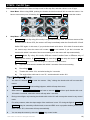
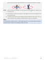
Calibration procedure
STEP1:
Enter calibration mode: quickly switch the control mode switch from Manual Mode to GPS Atti.
Mode and back to Manual Mode
for 6 to 10 times, The LED indicator will turn on constantly
blue;
STEP2:
Calibration in horizontal: rotate your multi rotor along the horizontal axis until the LED changes
to constant green, then go to the next step;
STEP3:
Calibration in vertical: while the LED is green, hold your multi rotor vertically and rotate it along
©2012 DJI Innovations. All Rights Reserved.
39 |
with its vertical axis, keep rotating until the LED turns off, meaning the calibration is finished.
STEP4:
After you finished the calibration, The LED indicator will show whether the calibration was
successful or not:
If the LED turns on white for 3 seconds, then the calibration was successful, calibration mode
will exit automatically.
If the LED quickly flashes red, the calibration has failed. Switch the control mode switch one
time to cancel the current calibration, and then re-start from step 1 for re-calibration.
Tips:
If you keep having calibration failure, it might suggest that there is very strong magnetic interference
around the GPS & Compass module, please avoid flying in this area.
©2012 DJI Innovations. All Rights Reserved.
40 |
Test Flying
Before First Flight
Note:
Make sure you have assembled your multi rotor correctly.
Make sure you have done the configuration procedure correctly.
Any of the following may lead to a possible dangerous accident if incorrect, double check all these
items:
Rotation direction of all motors is correct
Propellers are installed correctly and on the correct motors
IMU installation is correct
All Connections are correct, including between the MC and ESC
In Atti and GPS Atti mode, throttle stick center position is for 0m/s in the vertical direction. If you
lower the throttle stick to the bottom during the flight, the multi-rotor will descend; If you lower the
stick to the bottom on the ground, it will stop the motors after 3 seconds. However, slow spinning
motors will affect the flight performance; we advise to keep the throttle stick position higher than
10% during the flight! In Manual Mode it will stop the motors when the throttle stick is below 10%.
Make sure you switch on the transmitter first, then power on the multi-rotor! (Power off the
multi-rotor first then switch off the transmitter, after landing!)
Please carry out the test flights and gain adjustment with Atti. Mode in an open area without a heavy
wind! Please read the first step of Autopilot in Configuration to learn how to adjust the gains.
Flying
STEP1:
Make sure your batteries are fully charged for your transmitter, the MC and all the devices on
your multi rotor;
STEP2:
Check all connections and wiring, and make sure they are in good condition and secure
STEP3:
Switch on the transmitter first, then power on your multi-rotor!
STEP4:
Switch the control mode switch on your transmitter, and make sure it is working properly.
Check using the LED indicator to specify the current working mode for the MC. See Appendix for
details about LED indicator;
STEP5:
Switch the controller to Atti. Mode. Use any safe method to do the following test: Increase
the throttle to 20% slowly within 3 seconds after executing CSC and make sure all the motors are
working, and then try to move the transmitter sticks lightly in Roll, Pitch and Yaw to feel if your multi
rotor moves in the corresponding direction. If not, go back to the Configuration Procedure and
correct your settings.
©2012 DJI Innovations. All Rights Reserved.
41 |
Tips:
After a successful test flight, the preparation before taking off can be simplified: Put your multi rotor on
level ground, turn on the transmitter first, power on the multi rotor, when the LED light starts to blink
normally, you can take off in Atti. Mode.
©2012 DJI Innovations. All Rights Reserved.
42 |
Flying with GPS
Before Flying with GPS
Note:
When the system is powered on, you must not move your multi rotor or sticks on the transmitter until
the system initialization is finished (about 5 second).
Make sure the GPS signal is good, without red blinking LED. Otherwise the multi rotor will drift without
stick commands.
Please avoid using the MC system in the following areas, where the GPS signal is most likely weak or
totally obstructed:
Built-up Urban area with many buildings
Tunnels
Under bridges
Tips:
Should you find the multi-rotor does not fly straight in forward flight, you might need to re-mount the GPS
module in an offset angle as shown in the diagram below. Θ in the diagram is the offset angle.
Actual fli
ion
ght direct
θ
Objective flight direction
GPS mounting direction
1
Without GPS offset angle
With GPS offset angle
2
3
θ
Actual flight direction
Objective flight direction
GPS mou
nting dire
ction
©2012 DJI Innovations. All Rights Reserved.
43 |
Enhanced Features
Attitude Control When One Motor Output Has Failed
This feature is for Hexa-rotor, including Hexa-rotor I, Hexa-rotor V, Hexa-rotor IY and Hexa-rotor Y.
The WKM can still control the attitude of the Hexa-rotor for a safe landing when one motor output of the
Hexa-rotor has failed, for example, one motor is stopped or one propeller is broken, etc.
The control mode of WKM should be in Atti. Mode or GPS Atti. Mode. The aircraft will rotate, due to an
imbalance of torque; however, it can still be controlled by the TX.
Select Course lock or home lock mode for flying the aircraft into a safe area to land when the aircraft is far
away or the attitude can’t be recognized. Even when the multi rotor is rotating, using Course lock or home
lock mode will allow you to move the multi rotor in the corresponding Tx stick direction.
Flight Limits Setting
Height Limit
If height restriction is needed, please turn to the “Tool” tab of the assistant software. Click ON and write a
value (Range: 20~300m) to the Max Height box, so that the aircraft flight height will not higher than the
max-height in any control mode (Manual/ATTI./GPS ATTI. Mode). However, the FailSafe and the Ground
Station operation are not restricted to this height limit. If no height limit is needed, please click OFF.
Distance Limit
If distance restriction is needed, please turn to the “Tool” tab of the assistant software. Click ON and write a
value (Range: 30~500m) in the Max Radius box, so that the distance from the aircraft to the Home-point will
not be longer than the max-radius you set. The Distance Restriction function ONLY works in GPS ATTI. Mode.
The aircraft may fly out of the restriction when emergency brake is carried out at the border (the buffer zone is
about 10m), if it flies out of the restricted distance the Control Mode LED will blink Cyan. However, the
FailSafe and the Ground Station operation are not restricted to this distance limit. If no distance limit is
needed, please click OFF.
However, the FailSafe and the Ground Station operation are not restricted to this distance limit. If no distance
limit is needed, please click OFF.
©2012 DJI Innovations. All Rights Reserved.
44 |
Fix the TBE (Toilet Bowl Effect) Problem
When flying in GPS ATTI. Mode and the compass calibration has been done correctly, should you find the
aircraft rotating (Toilet bowl effect), or drifting when hovering. Please check the GPS module mounting
orientation and then re-do the compass calibration. Carry out the following procedure to re-mount the GPS
module.
In the following diagram (view from the top), the aircraft can appear to be rotating in both clockwise and
counter-clockwise direction, please re-mount the GPS module correspondingly.
is the rotating direction of aircraft,
is the nose direction of aircraft,
is the arrow direction on the GPS module, θ is the offset angle for GPS re-mounting(about 10~30o)
Clockwise rotating
GPS re-mounting
θ
Counter Clockwise rotating
GPS re-mounting
θ
©2012 DJI Innovations. All Rights Reserved.
45 |
Appendix
Customize Motor Mixer
For a multi rotor, the roll, pitch, yaw and vertical axes are contributed by the combination of rotors’ outputs.
This procedure is called Mix Control. The proportion of rotors’ outputs is decided by the mechanical structure.
Customers can setup the motor output coefficients C in Motor Mixer Customize so as to realize the Mix
Control.
Before customization, you should following knowledge:
1.
Motor output = C ×Stick position (A or E or T or R).
Torque produced by motor = Motor output × Force arm of motor (L) = C × Stick position (A or E or T or
R) × L
2.
The range of C is from -100% to 100%. Maximum C in the same column is 100%. The bigger
absolute value of C, The great effect of stick position on motor output. Stick position will not
affect motor output when C is 0, which means the motor output is fixed.
3.
Each motor has four different output coefficients: CT, CY, CP, CR. E.g. CY2 represents coefficient of M2
in yaw control; CR5 represents coefficient of M5 in roll control.
4.
Motor output is relative to its rotation speed. The bigger output, the faster rotation speed. Negative
output does not represent counter rotation, but slower rotation speed. Motor is still spinning if its output
is 0.
5.
Throttle stick position (T): Pull stick T<0, multi-rotor moves down; Push stuck T>0 multi-rotor moves up;
Rudder stick position (R): Stick left R<0, multi-rotor nose left; Stick right R>0, multi-rotor nose right;
Elevator stick position (E): Pull stick E<0 multi-rotor moves backward; Push stuck E>0, multi-rotor moves
forward;
Aileron stick position (A): Stick left A<0, multi-rotor moves left; Stick right A>0, multi-rotor moves right.
6.
Multi-rotor should keep balance along all the other axes when moves along one axis:
To keep throttle direction balance, sum of all motors’ output should be 0 when apply
rudder or pitch or roll stick command;
To keep yaw direction balance, sum of counter clockwise motors’ output should be
equal to sum of clockwise motors’ output when apply throttle or pitch or roll stick
command;
To keep pitch direction balance, total torques produced by motors at each side of pitch
axis should be the same when apply throttle or rudder or roll stick command;
To keep roll direction balance, total torques produced by motors at each side of roll axis
©2012 DJI Innovations. All Rights Reserved.
46 |
should be the same when apply throttle or rudder or pitch stick command。
7.
To pitch or roll control, proportion of coefficients of the motors at the same side of pitch or roll axis
should be equal to the proportion of force arms of those motors: Cm/Cn = Lm/Ln; Coefficient is 0%
if the force arm of that motor is 0.
M2
M2
M1
Roll Axis
M1
d
2d
M6
M5
M6
Yaw Axis
a
M4
M3
M4
Pitch Axis
a
M3
M1
M5
Now we take the Hexa-rotor V as an illustration to introduce how to customize motor mixer.
Throttle
Usually, we want push the throttle stick to ascend the multi-rotor; pull the throttle stick to descend the
multi-rotor; put the throttle stick at center point to hover the multi-rotor. We also want multi-rotor to keep
balance along all the other axes when apply the throttle stick command:
{
(𝐶𝑇1 +
(𝐶𝑇1
(𝐶𝑇2
+
(𝐶𝑇2 + 𝐶𝑇4 + 𝐶𝑇6 ) × 𝑇 (To keep yaw direction balance)
+ 𝐶𝑇2 ) × 𝑇 × 𝑎 = (𝐶𝑇4 + 𝐶𝑇5 ) × 𝑇 × 𝑎 (To keep pitch direction balance)
𝐶𝑇4 + 2𝐶𝑇3 ) × 𝑇 × 𝑑 = (𝐶𝑇1 + 𝐶𝑇5 + 2𝐶𝑇6 ) × 𝑇 × 𝑑 (To keep roll direction balance)
𝐶𝑇3 + 𝐶𝑇5
)×𝑇
=
1
As we defined before: Pull stick T<0, multi-rotor moves down; Push stuck T>0 multi-rotor moves up, we can
choose the following setup:
M2
M2
M1
Roll Axis
M1
d
M6
M5
Yaw Axis
M4
M6
a
M4
2d
M3
Pitch Axis
a
M3
M1
M5
Now if push the throttle stick, the sum of all motors output (CT1 + CT2 + CT3 + CT4 + CT5 +CT6)×T is positive,
then multi-rotor moves up; pull the throttle stick, the sum of all motors output (CT1 + CT2 + CT3 + CT4 + CT5
+CT6)×T is negative, then multi-rotor moves down. And the balance along all the other axes can be derived by
substituting the throttle stick command into equations set 1.
©2012 DJI Innovations. All Rights Reserved.
47 |
Yaw
The movement about yaw axis is produced by the counter torque force from the rotation of propeller. In our
example, M1 M3 M5 produce clockwise torque force; M2 M4 M6 produce counter clockwise torque force.
When the hexa-rotor is hovering, all the rotors are spinning at the same angular velocity, which means the
clockwise torque force equals to counter clockwise torque force, and this produces exactly 0 angular
acceleration about yaw axis. Therefore, when the rotate speed of M1 M3 M5 is larger than M2 M4 M6,
hexa-rotor spins clockwise; when the rotate speed of M1 M3 M5 is smaller than M2 M4 M6, hexa-rotor spins
counter clockwise. We also want multi-rotor to keep balance along all the other axes when apply the yaw stick
command:
(𝐶𝑅1 + 𝐶𝑅2 + 𝐶𝑅3 + 𝐶𝑅4 + 𝐶𝑅5 + 𝐶𝑅6 ) × 𝑅 = 0 (To keep throttle direction balance)
(𝐶𝑅1 + 𝐶𝑅2 ) × 𝑅 × 𝑎 = (𝐶𝑅4 + 𝐶𝑅5 ) × 𝑅 × 𝑎 (To keep pitch direction balance)
{
(𝐶𝑅2 + 𝐶𝑅4 + 2𝐶𝑅3 ) × 𝑅 × 𝑑 = (𝐶𝑅1 + 𝐶𝑅5 + 2𝐶𝑅6 ) × 𝑅 × 𝑑 (To keep roll direction balance)
2
As we defined before: Stick left R<0, multi-rotor nose left; Stick right R>0, multi-rotor nose right, we can
choose the following setup:
M2
M2
Roll Axis
M1
M1
d
M6
M5
Yaw Axis
M4
M6
a
M4
M3
Pitch Axis
a
2d
M3
M1
M5
Now if move the yaw stick right, the sum of M1, M3, M5 output (CR1 + CR3 + CR5) ×R is positive, the sum of M2,
M4, M6 output (CR2 + CR4 + CR6) ×R is negative, then the clockwise torque force is larger than counter
clockwise torque force, multi-rotor nose right; if move the yaw stick left, the sum of M1, M3, M5 output (CR1 +
CR3 + CR5) ×R is negative, the sum of M2, M4, M6 output (CR2 + CR4 + CR6) ×R is positive, then the clockwise
torque force is smaller than counter clockwise torque force, multi-rotor nose left. And the balance along all the
other axes can be derived by substituting the yaw stick command into equations set 2.
Pitch
The movement about the pitch axis is produced by the differential output of M1+M2 and M4+M5. Since M3
and M6 are on the pitch axis, they do not contribute and torque. You can just keep the rotation speed of M3
and M6 the same as hovering, so CP3 and CP6 are 0. Increase output of M4, M5 and decrease output of M1,
M2, multi-rotor moves forward; decrease output of M4, M5 and increase output of M1, M2, multi-rotor moves
backward. We also want multi-rotor to keep balance along all the other axes when apply the pitch stick
©2012 DJI Innovations. All Rights Reserved.
48 |
command:
(𝐶𝐸1 + 𝐶𝐸2 + 𝐶𝐸3 + 𝐶𝐸4 + 𝐶𝐸5 + 𝐶𝐸6 ) × 𝐸 = 0 (To keep throttle direction balance)
{ (𝐶𝐸1 + 𝐶𝐸3 + 𝐶𝐸5 ) × 𝐸 = (𝐶𝐸2 + 𝐶𝐸4 + 𝐶𝐸6 ) × 𝐸 (To keep yaw direction balance)
(𝐶𝐸2 + 𝐶𝐸4 + 2𝐶𝐸3 ) × 𝐸 × 𝑑 = (𝐶𝐸1 + 𝐶𝐸5 + 2𝐶𝐸6 ) × 𝐸 × 𝑑 (To keep roll direction balance)
3
Also proportion of coefficients of the motors at the same side of pitch axis should be equal to the proportion of
force arms of those motors: 𝐶𝐸1 ∶ 𝐶𝐸2 = 𝐶𝐸4 ∶ 𝐶𝐸5 = 𝑎: 𝑎 = 1: 1 . As we defined before: Pull stick E<0
multi-rotor moves backward; Push stuck E>0, multi-rotor moves forward, we can choose the following setup:
M2
M2
M1
Roll Axis
M1
d
M6
M5
Yaw Axis
M4
M6
a
M4
2d
M3
Pitch Axis
a
M3
M1
M5
Now if push the pitch stick, the sum of M1, M2 output (CE1 + CE2) ×E is negative, the sum of M4, M5 output
(CE4 + CE5) ×E is positive, then multi-rotor moves forward; if pull the pitch stick, the sum of M1, M2 output (CE1
+ CE2) ×E is positive, the sum of M4, M5 output (CE4 + CE5) ×E is negative, then multi-rotor moves backward.
And the balance along all the other axes can be derived by substituting the pitch stick command into
equations set 3.
Roll
The theory of movement about the roll axis is the same with pitch axis. However there is no motor on the axis
in this case, no coefficient is 0%. We also want multi-rotor to keep balance along all the other axes when
apply the roll stick command:
(𝐶𝐴1 + 𝐶𝐴2 + 𝐶𝐴3 + 𝐶𝐴4 + 𝐶𝐴5 + 𝐶𝐴6 ) × 𝐴 = 0 (To keep throttle direction balance)
{(𝐶𝐴1 + 𝐶𝐴3 + 𝐶𝐴5 ) × 𝐴 = (𝐶𝐴2 + 𝐶𝐴4 + 𝐶𝐴6 ) × 𝐴 (To keep yaw direction balance)
(𝐶𝐴1 + 𝐶𝐴2 ) × 𝐴 × 𝑎 = (𝐶𝐴4 + 𝐶𝐴5 ) × 𝐴 × 𝑎 (To keep pitch direction balance)
4
Also proportion of coefficients of the motors at the same side of roll axis should be equal to the proportion of
force arms of those motors: 𝐶𝐸2 ∶ 𝐶𝐸3 ∶ 𝐶𝐸4 = 𝐶𝐸1 ∶ 𝐶𝐸6 ∶ 𝐶𝐸5 = 𝑑: 2𝑑: 𝑑 = 1: 2: 1. As we defined before: Stick left
A<0, multi-rotor moves left; Stick right A>0 multi-rotor moves right, we can choose the following setup:
©2012 DJI Innovations. All Rights Reserved.
49 |
M2
M2
Roll Axis
M1
d
M1
M6
M5
Yaw Axis
M4
M6
a
M4
M3
Pitch Axis
a
2d
M3
M1
M5
Now if move the roll stick right, the sum of M2, M3, M4 output (CA2 + CA4 + 2CA3) ×A is positive, the sum of M1,
M5, M6 output (CA1 + CA5 + 2CA6) ×A is negative, then multi-rotor moves right; if move the roll stick left, the
sum of M2, M3, M4 output (CA2 + CA4 + 2CA3) ×A is negative, the sum of M1, M5, M6 output (CA1 + CA5 + 2CA6)
×A is positive, then multi-rotor moves left. And the balance along all the other axes can be derived by
substituting the roll stick command into equations set 4.
Summary
1.
Once you choose to customize, all coefficients are configurable. However, you only have to setup as
many as you need. Leave the rest 0%.
2.
Make sure you are clear about the definition of the positive and negative. Make sure you are also clear
about the relationship between the output quantity and motor rotation speed.
3.
Usually, the coefficients of throttle and yaw are 100% or -100%. The rest of the coefficients should be
decided by the proportion of force arms of the motors.
4.
The method introduced in this section is only suitable for central symmetry multi rotor.
©2012 DJI Innovations. All Rights Reserved.
50 |
Multi-Rotors Supported
For coaxial propellers: Blue propeller is at Top; Red propeller is at Bottom. Otherwise all propellers are at top.
M1
M2
M2
M1
M3
M4
M4
I4
M3
X4
M1
M2
M2
M1
M6
M3
M1
M5
M3
M4
M4
I6
M1,4
M2,5
M3,6
M2
X6
M2,5
M1,4
IY6
M8
M3
M5
M3,6
M1
M2
M6
Y6
M1
M3
M8
M4
M7
M2,6
M1,5
M3,7
M4,8
M7
M4
M6
M5
I8
©2012 DJI Innovations. All Rights Reserved.
M5
M6
V8
X8
51 |
Port Description
Main Controller
A
For roll control (left/right)
E
For pitch control (front/back)
T
For throttle control
Or to gimbal roll servo
R
For rudder control
Or to gimbal pitch servo
U
For Control Mode Switch
X1
For voltage monitor (Connect with PMU V-SEN port)
X2
For D-Bus (S-Bus/S-Bus2 compatible)
Or for gain tuning
Or for IOC switch
X3
For gimbal pitch control
Or for gain tuning
Or for switch go-home
M6
To #6 rotor
M5
To #5 rotor
M4
To #4 rotor
M3
To #3 rotor
M2
To #2 rotor
M1
To #1 rotor
F2
To gimbal pitch servo
Or to #8 rotor
F1
To gimbal roll servo
Or to #7 rotor
Micro-B USB port: PC connection for configuration and firmware upgrades.
CAN-Bus port: MC uses CAN-Bus to power and communicate with other WKM modules.
(In three-pin ports, pins near the nicks are signal pins.)
Power Management Unit
V-SEN
For monitoring battery voltage and supplying power to receiver and other electronic
devices. (Connect with MC X1 port)
PW
White wire (signal wire) output: ±3.3V
Red wire (power wire) output: 3A@5V
For supplying power to WKM system.
Output: Max [email protected]
©2012 DJI Innovations. All Rights Reserved.
52 |
LED Description
Flight States
Manual Mode
Atti. Mode
GPS Atti. Mode
IOC
Tx Signal Lost
GPS satellites < 5
GPS satellites < 6
GPS satellites < 7
Attitude & GPS good
Attitude status fair
Attitude status bad
IMU data Lost
Flashing indications of
,
,
are: Single flash, all the Tx sticks are at center position, multi rotor
hovering; Double flash, Tx stick(s) not at center position, speed command is not zero.
Compass Calibration
Begin horizontal calibration
Begin vertical calibration
Calibration finished
3 seconds
Calibration or others error
Low Voltage Warning
First level protection
Second level protection
Successful Recording
Every time the aircraft records a home-point successfully
Manually or Automatically Recording is successful
in Couse Lock and POI flying
Main Controller LED
MC is functioning correctly.
Boot loader mode, MC is waiting for firmware upgrade.
Firmware upgrade has finished. MC is waiting for reboot.
Error occurred during firmware upgrade, MC reboot is required.
or
PMU LED
PMU connection is correct.
Connection between PMU and battery is wrong (polarity error).
©2012 DJI Innovations. All Rights Reserved.
53 |
Recommended Setting
Configuration Information
No.
Basic Gain
Attitude Gain
Aircraft
Motor
ESC
Propeller
Battery
Weight
Pitch
Roll
Yaw
Vertical
Pitch
Roll
1
F450
DJI-2212
DJI-30A
DJI-8 Inch
3S-2200
1070 g
155
155
125
150
165
165
2
F550
DJI-2212
DJI-30A
DJI-8 Inch
4S-3300
1640 g
170
170
150
140
170
170
3
S800
DJI-4114
DJI-40A
6S-15000
4770 g
200
200
195
175
190
190
DJI-4114
DJI-40A
6S-10000
6100 g
240
240
200
200
220
220
4
S800&Z15
&Camera
DJI-15 Inch
Carbon
DJI-15 Inch
Carbon
54
Specifications
General
Built-In Functions
Three Modes Autopilot
S-Bus/S-Bus2 Receiver Supported
PPM Receiver Supported
Intelligent Orientation Control
2-axle Gimbal Support
Multi Output Frequency Supported
Enhanced Fail Safe
Low Voltage Protection
Peripheral
Supported Multi-rotor
Quad-rotor: I4, X4;
Hexa-rotor: I6, X6, Y6, IY6;
Octo-rotor: X8, I8, V8.
Supported ESC output
400Hz refresh frequency.
Recommended Transmitter
Only PCM or 2.4GHz with minimum 7 channels and
FailSafe function available on all channels.
Recommended Battery
2S ~ 6S LiPo
Assistant Software System Requirement
Windows XP SP3 / 7
Electrical & Mechanical
Power Consumption
MAX 5W
(0.9A@5V, [email protected], [email protected], 0.4A@8V)
Operating Temperature
-5°C to +60°C
Total Weight
<= 118g (overall)
Dimensions
MC: 51.2mm x 38.0mm x 15.3mm
IMU: 41.4mm x 31.1mm x 27.8mm
GPS & Compass: 50mm (diameter) x 9mm
LED Indicator: 25mm x 25mm x 7mm
PMU: 39.5mm×27.5mm×9.7mm
Flight Performance (can be effected by mechanical performance and payloads)
Hovering Accuracy (GPS Mode)
Vertical: ± 0.5m
Horizontal: ± 2m
Maximum Wind Resistance
<8m/s (17.9mph / 28.8km/h)
Max Yaw Angular Velocity
150deg/s
Max Tilt Angle
35°
Ascent / Descent
±6m/s
55