1
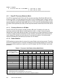
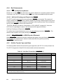
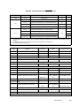
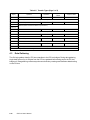
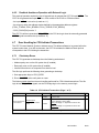
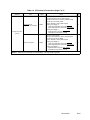
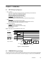
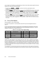
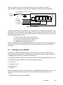
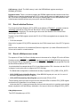
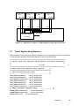
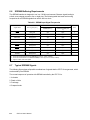
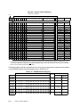
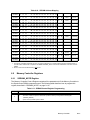
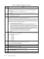
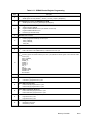
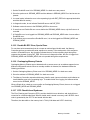
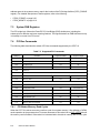
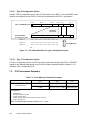
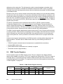
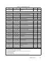
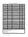
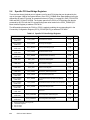
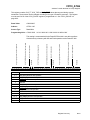
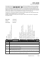
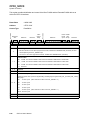
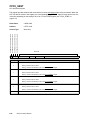
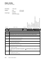
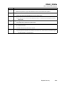
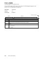
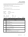
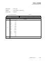
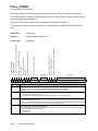
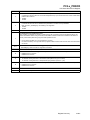
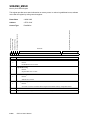
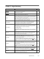
address space in the system memory map for the location of the PCI bridge facilities (PCP0_PCIBAR
register). For detailed descriptions of these registers, refer to the following:
• “CPC0_PCIBAR” on page 9-23
• “CPC0_ABCNTL” on page 9-10
7.3
System PHB Registers
The PCI bridge logic follows the PowerPC PCI Host Bridge (PHB) Architecture, including the
enhanced error detection and error reporting features. The logic deviates from PHB Architecture only
in its ability to recover from PCI errors.
7.4
PCI Bus Commands
The following table describes the subset of PCI bus commands supported by the CPC710.
Table 7-3. Supported PCI Commands
C/BE[3:0]
7.4.1
Command
Support as Initiator
Support as Target
0000
Interrupt Acknowledge
Yes
No
0001
Special Cycle
Yes
No
0010
I/O Read Cycle
Yes
No
0011
I/O Write Cycle
Yes
No
0100
Reserved
0101
Reserved
0110
Memory Read
Yes
Yes
0111
Memory Write
Yes
Yes
1000
Reserved
1001
Reserved
1010
Configuration Read
Yes
Yes (PCI64 only)
1011
Configuration Write
Yes
Yes (PCI64 only)
1100
Memory Read Multiple
No
Yes
1101
Dual Address Cycle
No
No
1110
Memory Read Line
Yes
Yes
1111
Memory Write and Invalidate
Yes
Yes
PCI Master Memory Read Cycles
When the CPC710 receives a memory read bus cycle from system memory, it first initiates a CLEAN
cache operation to the processor bus. Processor accesses to this cache line are SYS_ARTRYed until
the memory read is finished. If the cache line is determined to be stale in memory, the PCI bus cycle
7-2
CPC710 User’s Manual