1
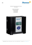
Solar pumping inverter
Installation and user
manual
D o c u m e n t a t i o n
PN-AP
320046A_UM_EN
February 2011
Phaesun France SAS
145 rue de la Marbrerie
Boîte aux lettres n°4
34740 Vendargues, France
Tel: +33 (0) 4 67 04 38 40
Fax: +33 (0) 4 67 41 09 79
www.phaesun.fr
[email protected]
PN-AP
Installation and user manual
320046A_UM_EN
February 2011
Page 2 / 22
PN-AP
Installation and user manual
Summary
1.
Safety recommendations.......................................................................................... 4
1.1.
1.2.
1.3.
1.4.
Compulsory safety instructions ....................................................................................................... 4
What NOT to do .............................................................................................................................. 4
Safety protection for installation, handling and maintenance ...................................................... 5
Responsible behavior....................................................................................................................... 5
1.4.1.
1.4.2.
1.4.3.
1.4.4.
2.
Presentation and technical features ......................................................................... 7
2.1.
2.2.
2.3.
Application....................................................................................................................................... 7
Presentation of the PN-AP inverter ................................................................................................. 7
The main features of the PN-AP...................................................................................................... 7
2.3.1.
2.3.2.
2.3.3.
2.4.
2.5.
2.6.
Use ................................................................................................................................................................ 9
Operating information .............................................................................................................................. 10
Installation .............................................................................................................. 14
3.1.
3.2.
Installation instructions ................................................................................................................. 14
Wiring and commissioning ............................................................................................................ 15
3.2.1.
3.2.2.
3.2.3.
3.2.4.
4.
Managing the start-up phase after the night ........................................................................................... 7
Managing phases where the power available is not sufficient ............................................................... 7
Optimizing available input power (MPPT) ................................................................................................ 8
Technical features ............................................................................................................................ 8
Safety features ................................................................................................................................. 9
Use and operation ........................................................................................................................... 9
2.6.1.
2.6.2.
3.
Safety training ............................................................................................................................................. 5
Handling structures ..................................................................................................................................... 6
Working on photovoltaic modules ............................................................................................................ 6
Electrical wiring............................................................................................................................................ 6
Order of wiring : ........................................................................................................................................ 16
Wiring the modules ................................................................................................................................... 17
Electrical connection of the inverterr....................................................................................................... 18
Commissioning........................................................................................................................................... 19
EMC and RoHS certifications .................................................................................. 20
320046A_UM_EN
February 2011
Page 3 / 22
PN-AP
Installation and user manual
1. Safety recommendations
1.1. Compulsory safety instructions
General danger
When installing a solar-powered pumping system, it is vital to adhere to
standard safety recommendations and working practices related to
international standards (electrical and handling)
Risk of electric shock
High voltage and / or current. Do not touch connectors or terminals without
using adequate protective insulation. Use insulated tools. Remove all items
liable to generate a short circuit (jewellery, etc.)
A fire extinguisher must be kept close by (e.g. in the vehicle)
In case of fire, use a CO2 or foam extinguisher. Spray on to the fire from a
distance of more than 50 cm
1.2. What NOT to do
Do not try to extinguish a fire with water
If the inverter or any other electrical device catches fire, do not try to extinguish
it with water, as you will risk being electrocuted.
Access prohibited unless authorized
Access to the generator assembly area is strictly forbidden to unauthorised
individuals.
Do not approach sources of heat or ignition near the inverter
Gases given off may well catch fire.
320046A_UM_EN
February 2011
Page 4 / 22
PN-AP
Installation and user manual
Strictly no smoking
This might damage electrical apparatus.
1.3. Safety protection for installation, handling and maintenance
The photovoltaic panels must be covered when working on any electrical
part of the installation (cloths, cardboard packaging used for the modules,
carpets, etc.)
Helps to avoid electrocution. Be careful not to scratch the modules!
Protective goggles must be worn
An electric arc may cause eye injuries.
Suitable footwear must be worn
Safety shoes must be worn whenever carrying out a handling operation.
Protective clothing recommended
Clothing made with synthetic materials should not be worn. Wear cotton
clothing that covers the whole body.
1.4. Responsible behavior
1.4.1. Safety training
Out of a concern to prevent accidents, we recommend that all staff receive suitable training
related to the contents of this document before installing or working on the system
concerned.
320046A_UM_EN
February 2011
Page 5 / 22
PN-AP
Installation and user manual
1.4.2. Handling structures
Any installation or other work on structures making up the photovoltaic field should be
avoided during high winds.
Particular attention should be paid to handling parts of the structure, especially when working
at height on high structures. We strongly recommend that a safety helmet is worn.
For more detailed information, please refer to the corresponding chapter on structure
assembly.
1.4.3. Working on photovoltaic modules
When altering the wiring on modules, you are strongly advised to cover all the modules in the
sub-field concerned [e.g. with the modules packaging]. The current generated by a single
module may be enough to kill beyond a certain voltage (50 Volts of continuous current). It is
therefore vital to guard against any electric shock.
1.4.4. Electrical wiring
Poor quality wiring may lead to electrical accidents. All electrical wiring must be carried out in
compliance with standard NFC15-100 by qualified technicians or a suitably trained individual.
320046A_UM_EN
February 2011
Page 6 / 22
PN-AP
Installation and user manual
2. Presentation and technical features
2.1. Application
Photovoltaic pumping helps meeting the vital water supply needs of populations and to solve
the problems of providing energy for agricultural and trade uses in areas where there is no
reliable electrical supply.
Prior to from the pumping system, the photovoltaic generator produces continuous current
that has to be converted into alternating current to supply the motor-pump further down the
line. In a system that works on sunlight, i.e. without a battery, motor speed has to be adjusted
to the light intensity available at any given moment.
This function is carried out by the inverter.
2.2. Presentation of the PN-AP inverter
The PN-AP converter is a three-phase, variable frequency inverter for use on standard pumps
(3 x 230VAC).
The product is specially designed to meet the specific conditions involved in solar-powered
pumping and takes account of all the requirements. It offers an effective, compact solution to
meet the special demands of this application.
2.3. The main features of the PN-AP
2.3.1. Managing the start-up phase after the night
As the only energy source is the photovoltaic generator, the PN-AP is designed to start up
gradually in the morning, ensuring that the energy available is sufficient.
2.3.2. Managing phases where the power available is not sufficient
In some cases (evening, cloud passing over, shadow), the energy source falls rapidly and,
sometimes, the power available is not sufficient to operate the pump properly. The PN-AP
inverter is designed to manage these events, thus avoiding the pump having to start up
repeatedly, and power supply at too low a frequency, causing damaging bubbling in the
pump.
320046A_UM_EN
February 2011
Page 7 / 22
PN-AP
Installation and user manual
2.3.3. Optimizing available input power (MPPT)
Phaesun has designed and developed an innovative procedure for Maximum Power Point
Tracking (MPPT).
MPPT is used to get the best from the input power available. The power supplied by the solar
panels will depend on the level of sunshine and the temperature of the solar cells.
To maximise the effectiveness of the energy conversion device and therefore get the best use
of the solar panels, it needs to be permanently working as near as possible to the point where
the power, according to the voltage in the generator, is at its maximum.
2.4. Technical features
PN-AP pumping inverter
Unit
Specifications / details
Nominal input voltage
[VDC]
325
Over voltage
[VDC]
450
Acceptable input voltage without
degradation
[VDC]
500
Operating input range
[VDC]
200 à 360
Nominal voltage per phase
[VAC]
230
Maximum output frequency
[Hz]
53
Minimum output frequency
[Hz]
6
Nominal maximum power of the
standard asynchronous motor
[kW]
5.5
[%]
> 97
Operating temperatures
[°C]
-10 à 75
Relative humidity
[%]
95
Input
Output
Output efficiency
Main characteristics
Type of protection
IP55
Casing
Beige Anodized
Cover
Stainless steel
Tropicalized version
Yes
Table 1. General features of the PN-AP inverter
320046A_UM_EN
February 2011
Page 8 / 22
PN-AP
Installation and user manual
2.5. Safety features
The inverter contains a manually operated multipolar switch to provide load cut-off or shut
down and safety cut-out. In addition, in position O, the lid may be opened.
A number of safety features are incorporated into our product to provide greater reliability.
These include protection against:
•
•
•
•
•
•
•
too high input voltage on the continuous bus,
overload on the pump side (jamming),
inversion of module polarity,
inverter at too high a temperature,
lack of water in the well,
short-circuit on the pump side,
full tank (combined with a tank fitted with a ballcock, optional),
2.6. Use and operation
2.6.1. Use
The various operating situations are shown by leds on the front of the inverter. These are
explained below:
Figure 1. Front of the PN-AP inverter
320046A_UM_EN
February 2011
Page 9 / 22
PN-AP
Installation and user manual
2.6.2. Operating information
2.6.2.1. Green “Operation” / “Fonctionnement” led on
State
Operating,
System behavior
The inverter is operating normally. Operating parameters (DC input current,
Motor frequency, etc.) may be accessed on the LCD display.
Display messages
V entree : xxxV
V in
: xxxV
I entree : xx.xA
I in
: xx.xA
P entree : xxxxW
P in
: xxxxW
Temp
Temp
: xx°C
: xx°C
Frequence: xxHz
Frequency: xxHz
Moves automatically from one to the other every 2 seconds
2.6.2.2. No led on
State
The inverter is not operating but is not signalling any fault.
Possible causes
Insufficient sunlight (night-time, clouds, mist, etc…)
System behavior
If input power allows, the inverter attempts to start-up. If available input power is
not sufficient to operate the pump properly (risk of damage to the motor due to
lack of cooling), the inverter stops the operation and will make a new attempt
every 2 minutes, until available power is sufficient.
320046A_UM_EN
February 2011
Page 10 / 22
PN-AP
Installation and user manual
Display messages
P entree faible
Low input power
2.6.2.3. “Lack of water “/ “manque d’eau” led on
State
The inverter is stopped.
Possible causes
Lack of water in the well,
Bubbling in the pump,
System behavior
The inverter stops and then tries to start up again 2 hours later. If the problem has
not disappeared, the same procedure occurs again. If the two attempts are
unsuccessful, the inverter switches itself off for the day.
The inverter automatically resets every night, which means that a test procedure
can be carried out daily (detection plus 2 trials) to detect a return to normal
operation.
Display messages
Manque d’eau
Lack of water
2.6.2.4. “ Full Tank “ / “Château d’eau plein” led on
State
The inverter is stopped.
Possible causes
The tank is full.
System behavior
The level detector in the tank indicates that the tank is full via a switch (dry
contact).
The inverter stops until the water level drops below the lower threshold. When
the level drops below the lower threshold (change of state of TOR input), the
inverter and pump start up again.
320046A_UM_EN
February 2011
Page 11 / 22
PN-AP
Installation and user manual
Display messages
Reservoir plein
Full tank
2.6.2.5. “Overheating” / “surchauffe” led on
State
The temperature of the system is too high. The operating cannot be assumed.
Possible causes
Le PN-AP has been placed in the sun in poor conditions of ventilation,
The converter has been subjected to too high a load.
An internal problem (in particular, the power module has become separated from
the heat sink) requires manual intervention.
System behavior
The inverter switches into fault mode (ceases operation), then attempts to start up again 2
hours later. If the problem has not been resolved, the same procedure occurs as before. If
the two attempts are unsuccessful, the inverter switches itself off for the day
The inverter is re-configured every night, which means that a test procedure can
be carried out daily (detection plus 2 trials) to detect a return to normal operation.
Display messages
Surchauffe
Overheating
2.6.2.6. “serious failure”/ “panne grave” led on
State
Overload (current absorbed by the pump too high) or overvoltage (input voltage
too high).
Possible causes
Pump blocked,
Phase fault on the alternating current side,
Overload on the PV input,
Short-circuit on the pump side,
Poor wiring on the PV generator, causing too high a voltage.
320046A_UM_EN
February 2011
Page 12 / 22
PN-AP
Installation and user manual
System behavior
Once it has detected a current or voltage higher than reference values, the
inverter switches itself off. The inverter will only start up again :
•
•
after manual action (engaging the switch: switching to OFF, waiting for 2
minutes, then switching to ON),
on the following day, when the sun is shining again.
Display messages
Surcharge AC
320046A_UM_EN
AC Overload
February 2011
Page 13 / 22
PN-AP
Installation and user manual
3. Installation
Important reminder:
The modules must be covered while they
are being wired together (cloths,
cardboard module packaging, carpet,
etc.)
Operating voltages may be fatal!
Be careful not to scratch the modules!
3.1. Installation instructions
The inverter is installed beneath the photovoltaic generator, on two specially designed
supports. To avoid subjecting the inverter to bad weather, it should be fixed under a panel, as
shown in the diagram, and not on one of the structure’s feet. The inverter should be mounted
or dismantled before any wires are connected.
Figure 2. Installing the inverter at the back of the photovoltaic field nearest to the well
320046A_UM_EN
February 2011
Page 14 / 22
PN-AP
Installation and user manual
3.2. Wiring and commissioning
The safety recommendations set out at the beginning of this document must be followed in
order to guard against electric shock. The system is powered by a generator operating at 500V
(maximum) and under continuous current: direct accidental contact is fatal to humans.
Risk of fatal electric shock!
Follow the wiring instructions in chronological order. The installer should take particular
care to ensure that the PCU / photovoltaic field connection is made at night only, with the
modules covered.
320046A_UM_EN
February 2011
Page 15 / 22
PN-AP
Installation and user manual
3.2.1. Order of wiring :
Figure 3. General block diagram of the pumping system, order of wiring for the inverter
Refer to figures 4 and 5 for stages 1, 2 et 5.
320046A_UM_EN
February 2011
Page 16 / 22
PN-AP
Installation and user manual
3.2.2. Wiring the modules
Figure 4. Wiring modules in series
320046A_UM_EN
February 2011
Page 17 / 22
PN-AP
Installation and user manual
3.2.3. Electrical connection of the inverterr
Take great care whilst wiring; the generator supplies high-voltage current.
Check that the switch on the front face is set at “O",
Open the inverter casing to gain access to the connection terminals,
Connect the motor supply wire to the three-phase inverter output (cf. diagram),
Connect the earth to the external threaded rod provided,
Check that the open-circuit voltage on the photovoltaic modules does not exceed 480
VDC,
Connect the solar-powered generator to the PN-AP, ensuring that polarity is correct.
The wires between the panels and the inverter should be as short as possible to avoid
loss of voltage,
Warning : Connection should be from the inverter to the modules to
avoid handling a live wire.
Where a system is fitted with the “full tank” option, the level regulator is connected to the
terminal block in the inverter casing.
+
Figure 5. Terminal block diagram with wiring instructions
320046A_UM_EN
February 2011
Page 18 / 22
PN-AP
Installation and user manual
3.2.4. Commissioning
Check that all connections have been made and that the pump is properly installed,
Place the switch in position “|”,
The PN-AP converter does not require any adjustments. It will start up
automatically. After the start-up period, it will turn the pump at a frequency
proportional to the level of sunlight.
Check the pump flow,
Stop the system using the switch and wait 2 minutes before handling to give the
capacitors time to discharge,
Risk of fatal electric shock!
Reverse two motor cable wires on the terminal block,
Repeat the commissioning procedure and check pump flow again. The better flow rate
indicates the pump’s correct rotation direction,
Once the whole procedure is completed, the system does not need to be handled again.
320046A_UM_EN
February 2011
Page 19 / 22
PN-AP
Installation and user manual
4. EMC and RoHS certifications
320046A_UM_EN
February 2011
Page 20 / 22
PN-AP
Installation and user manual
320046A_UM_EN
February 2011
Page 21 / 22
PN-AP
Installation and user manual
[email protected]
320046A_UM_EN
February 2011
Page 22 / 22