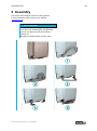
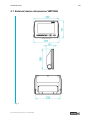
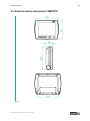
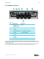
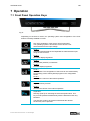
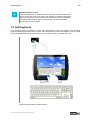
1
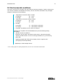
Version 2.2 Translation of the original instruction manual Instruction manual Terminals VMT8000 series Effective as of 06.07.2015 VMT8000 series 1 Table of Contents 1 Notes 1.1 1.2 1.3 1.4 General remark Limitation of liability Manufacturer Relevant device documentation 2 Safety instructions 2.1 2.2 2.3 2.4 2.5 2.6 2.7 2.8 2.9 3 3 3 3 3 4 Structure of safety instructions Graduation of risk level Explanation of used symbols Symbols Data, figures and modifications Trademarks Copyright Environmental conditions Standards 4 4 4 5 5 5 5 6 7 3 Operating and safety instructions 8 3.1 3.2 3.3 3.4 3.5 3.6 3.7 Operating location Damage due to improper use Warranty / repairs Intended use Improper use Treatment and disposal of lithium batteries Safety instructions 4 Product description 4.1 Device features 4.2 24 V/48 V DC* power supply 4.2.1 Release contact (IGN) 4.3 Autostart function 4.4 USB connections 4.4.1 Service slot 4.4.2 Front panel 4.5 Network connection 4.6 Serial interface COM1 4.7 Heater (optional) 5 Assembly 5.1 5.2 5.3 5.4 External device dimensions VMT8008 External device dimensions VMT8010 External device dimensions VMT8012 External device dimensions VMT8015 © ads-tec GmbH • Heinrich-Hertz-Str. 1 • 72622 Nürtingen 9 9 9 9 9 10 10 11 11 13 14 15 15 15 15 16 17 17 18 20 21 22 23 VMT8000 series 6 Putting into operation 6.1 6.2 6.3 6.4 6.5 6.6 Scope of delivery Check for operational readiness Order of steps during commissioning Operation Taking out of operation Available interfaces 7 Operation 7.1 7.2 7.3 7.4 7.5 Front Panel Operation Keys Soft keyboard Touch screen Status displays Speakers 8 Wireless 8.1 WLAN (optional) 8.2 Bluetooth (optional) 8.3 RFID reader (as an option) 8.4 RFID configuration 8.4.1 MIFARE 8.4.2 LEGIC 2 24 24 24 25 25 25 26 28 28 29 30 31 32 33 33 34 35 36 36 37 9 Drives 38 10 Software & driver installation 39 11 Maintenance 40 11.1 11.2 Information on maintenance Information on storage 40 40 12 Technical details 41 13 Service & support 42 13.1 13.2 ads-tec support Company address © ads-tec GmbH • Heinrich-Hertz-Str. 1 • 72622 Nürtingen 42 42 VMT8000 series 3 1 Notes 1.1 General remark This instruction manual is intended to ensure safe and efficient handling of the device. It must be accessible to all persons who are involved in installation and commissioning of the device and must be read and understood before any work is started. The instruction manual must be passed on to the device/system operator after commissioning has been completed. All of the safety notices and handling instructions given in the manual must be obeyed in order to ensure that work is carried out safely. Figures used in this instruction manual are provided for basic understanding and may differ from the actual design. The original version of this instruction manual was written in German. All non-German versions of this instruction manual are translations of the German instruction manual. 1.2 Limitation of liability ads-tec GmbH shall not be liable for personal injury, property damage or damage caused to the device as well as consequential damage that is/was the result of non-compliance with this instruction manual, improper use of the device, repairs and other actions on the device by unqualified electricians and electricians not certified by ads-tec, or that is/was the result of using unapproved replacement parts. Failure to observe the maintenance intervals shall also result in exclusion from liability. Furthermore, it is strictly forbidden to make any unauthorised alterations or technical modifications to the device. 1.3 Manufacturer The manufacturer of the product is ads-tec GmbH. The company is referred to in the following as adstec. 1.4 Relevant device documentation The following documents are decisive to device setup and operation: Instruction manual (this documentation): Contains information for installation, commissioning and operation of the device along with technical data of the device hardware. Website You can download drivers, software, user manuals, leaflets and flyers about the product from our website www.ads-tec.de. Recommendation for use: We would recommend to make use of our website contents www.ads-tec.de in order to use current data and to be quickly and comprehensively informed of any technical modification. © ads-tec GmbH • Heinrich-Hertz-Str. 1 • 72622 Nürtingen VMT8000 series 4 2 Safety instructions 2.1 Structure of safety instructions The signal word classifies the hazard. Reference to the type/consequences and source of the hazard is made underneath the signal word. Instructions for preventing the hazard are identified by an arrow (). SIGNAL WORD Type/consequences of hazard! - Source of hazard Measures to prevent hazard 2.2 Graduation of risk level The signal word classifies the hazard. Instructions for preventing the hazard are identified by an arrow (). 2.3 Explanation of used symbols DANGER Indicates an imminent danger. If not avoided, death or severe injury will result. WARNING Indicates a possible danger. If not avoided, death or severe injury could result. CAUTION Indicates a possible danger. If not avoided, light or minor injuries could result. ATTENTION Indicates a possibly damaging situation. If not avoided, the system or something in its surroundings could be damaged. Recommendation for use: The symbol "Recommendation for use" indicates terms and/or conditions that strictly need to be observed to ensure optimised and/or zero-defect operation. Tips and suggestions for the efficient use of the device and software optimisation are also provided. © ads-tec GmbH • Heinrich-Hertz-Str. 1 • 72622 Nürtingen VMT8000 series 5 2.4 Symbols Symbol Meaning Designation of batteries in accordance with § 13 of the German Battery Act (BattG). Batteries may not be disposed of with household waste, but must rather be disposed of separately. Used batteries must be returned to the point of sale or a disposal system. Labelling of electrical and electronic devices in accordance with § 7 of the German Electrical and Electronic Equipment Act (ElektroG). Electrical and electronic devices must not be disposed of with household waste, but must rather be taken to a collection point for waste electrical equipment. Such a collection point is generally operated by public waste management authorities, i.e., by municipalities. Symbol for the protective earth connection 2.5 Data, figures and modifications All data, text and figures were prepared to the best of our knowledge. They do not represent any assurance for the properties themselves. Despite taking utmost care, no liability can be assumed for accuracy, completeness and actuality of the information. Subject to changes. 2.6 Trademarks It is noted that any software and/or hardware trademarks and any company brand names mentioned in this documentation are all subject to the general trademark protection rights. StoraXe® and Big-LinX® are registered trademarks of ads-tec. All other third-party trademarks used are hereby acknowledged. In the case of infringement of trademark rights, ads-tec reserves the right to exercise all rights. 2.7 Copyright This instruction manual is protected by copyright. For the authorised user, simple usage rights are granted within the scope of the intent of the contract. Any modified use or exploitation of the provided content, particularly duplication, modification or publishing in whatever form is permitted only with the prior consent of ads-tec. In the case of copyright infringement, ads-tec reserves the right to exercise all rights. © ads-tec GmbH • Heinrich-Hertz-Str. 1 • 72622 Nürtingen VMT8000 series 6 2.8 Environmental conditions The device can be put into operation and used under the following conditions. Failure to observe any one of these conditions will invalidate the warranty. ads-tec cannot be held liable for any damages arising from improper use and handling. Temperature for devices without a heater in operation* -20 ... 55°C** for storage -30 ... 60°C Temperature for devices including a heater in operation* -30 ... 55°C for storage -30 ... 60°C Humidity In operation For storage 10 … 85% without condensate 10 … 85% without condensate Air quality: Air pollution level 3 or lower according to This device is compliant to the DIN EN 60068-2-27 (shock and bump) testing specification Vibration and shock resistance EN 60721-3-5 (06.1998), class 5M2 for HDD version, class 5M3 (terrestrial vehicles) for SSD version, 5 hours of noise-type vibrations; 3.6 g rms and 30 g peak value Additionally applies MIL-STD 810F (01.2000), annex C, figure 514.5C (US highway truck transportation) *(depending on mass storage device) ** The UL marking applies for operating temperatures up to max. 40°C and for devices without heater. © ads-tec GmbH • Heinrich-Hertz-Str. 1 • 72622 Nürtingen VMT8000 series 7 2.9 Standards This device is compliant with the provisions and safety objectives of the following EU directives: Standards This device is compliant with the CE mark test requirements as defined in the European test standards EN 55022 and EN 61000-6-2 This device is compliant with the DIN EN 60950 (VDE0805, IEC950) testing specifications on “Information technology equipment – Safety" This device is compliant with the DIN EN 60068-2-6 testing specifications (sinusoidal vibration) This device is compliant to the DIN EN 60068-2-27 (shock and bump) testing specification By using the CE conformity declaration in this document, you can find detailed information about the standards applicable to this device. For full compliance with the EMC legislation, all components and cables used for device connection must also be compliant with these requirements. Recommendation for use: Always use shielded bus and LAN cables with shielded plugs. ATTENTION Interference in residential environments This is a class A device. Class A devices may cause interference when used in residential environments. In this case, the operator can be requested to take appropriate measures and to pay any costs incurred as a result. © ads-tec GmbH • Heinrich-Hertz-Str. 1 • 72622 Nürtingen VMT8000 series 8 3 Operating and safety instructions The device operates under electrical voltage and contains highly sensitive components. Intervention by the user is required only for connecting the power supply lines. Should any further modifications be required, it is necessary to consult either with the manufacturer directly or with service personnel authorised by the manufacturer. The device must be de-energised during work. Appropriate measures must be taken to prevent electrostatic discharges on components. If the device is opened up by an unauthorised person, the user may be subject to hazards and the warranty is invalidated. General information All users must read this manual and have access to it at all times. Assembly, commissioning and operation may only be performed by qualified and trained personnel. The safety notices and the manual itself must be observed by all persons who work with this device. At the installation site the valid guidelines and regulations for accident prevention must be observed. The manual contains the most important instructions on how to use this device in a safe way. Appropriate storage, proper transport, installation and commissioning, as well as careful operation are prerequisites for ensuring safe and proper operation of the device. The device can be cleaned by using a soft cloth and a commercially available glass cleaning agent (e.g. Sidolin) with low alcohol content. ATTENTION Hazard due to damage to device Damage caused by connected peripherals or data loss All cable lines (power supply, interface cables) should only be connected while the device is switched off and de-energised. © ads-tec GmbH • Heinrich-Hertz-Str. 1 • 72622 Nürtingen VMT8000 series 9 3.1 Operating location The device is designed for use on support arm systems, wall and table mounting or on vehicles (commissioning trolleys, forklifts or similar). You have to take care that the environmental conditions specified in the technical data are met. Use in non-specified environments, i.e., on board ships, in explosive atmospheres or at extreme elevations, is prohibited. The device must not be used to control vehicles. It must be ensured that the device is installed properly. ATTENTION Hazard due to condensation Damage to electronic components caused by condensation resulting from temperature fluctuations. The device should only be switched on after it has acclimated to the ambient temperature! To avoid overheating in operation: The device must not be exposed to direct radiation by sunlight or any other heat source. 3.2 Damage due to improper use Should the control system have evident signs of damages caused, e.g., by improper operation or storage conditions or due to improper use or handling, the device must be shut down immediately. Ensure that it is secured against being started up accidentally. 3.3 Warranty / repairs During the device warranty period, any repairs must only be performed by the manufacturer or by service personnel that has been authorised by the manufacturer. 3.4 Intended use The device is used for visualisation and control as well as the acquisition of operating and machine data in the production environment. Another typical application is in logistics. Here, the device can be used for mobile data acquisition. The device is only to be assembled, installed and operated within the permissible specifications. Use in non-specified environments is prohibited. 3.5 Improper use Operation other than or beyond that described for the device shall be deemed improper use. The device is not allowed to be used to control vehicles or for applications for which further approvals beyond the manufacturer's declaration are necessary, e.g. applications with explosion hazard, medical technology, shipping industry. The device must not be put into operation in the case of transport damage or nonconformity with the specifications and, if necessary, must be taken out of operation in the case of changing conditions. In the case of improper use, ads-tec shall not accept responsibility or liability for injury or damage that is directly or indirectly attributable to the handling of the device. Should the device have evident signs of damages caused, e.g., by improper operation or storage conditions or due to improper use or handling, it must be shut down immediately. Ensure that it is secured against being started up accidentally. © ads-tec GmbH • Heinrich-Hertz-Str. 1 • 72622 Nürtingen VMT8000 series 10 3.6 Treatment and disposal of lithium batteries This device contains a lithium battery for supplying the system clock with power as long as the supply voltage is not connected. The battery has a life cycle of 3-5 years depending on which load is applied. ATTENTION Hazard due to thermal loads The more the battery is exposed to higher temperatures, the faster it ages. Avoid thermal loads. WARNING Hazard due to explosion Danger of explosion if using incorrect battery types. Use the battery type recommended by the manufacturer. Lithium batteries should not be exposed to fire, soldered, recharged, opened, short-circuited, reversed or heated above 100 °C and they should be disposed of properly as well as protected against sunlight, moisture and condensation. The battery type to be used is: ½ AA 3V Lithium Battery Type: FDK Corp. CR14250SE ads-tec part number: DZ-SONS-04100-0 The used lithium battery should be disposed of in accordance with local legal regulations. 3.7 Safety instructions ATTENTION Damage due to electrostatically sensitive components Damage to the device can be caused by electrostatically sensitive components. All installation and service work performed on the device must be performed only under safe, secure and de-energised conditions. Recommendation for use: Always adhere to the safety measures applicable when handling components at risk of being damaged by electrostatic discharges. The provisions of DIN EN 61340-5-1 / DIN EN 61340-5-2 apply © ads-tec GmbH • Heinrich-Hertz-Str. 1 • 72622 Nürtingen VMT8000 series 11 4 Product description 4.1 Device features Front view No. Description 1 Display with touch function 2 Front buttons 3 Front USB 4 Power-ON button © ads-tec GmbH • Heinrich-Hertz-Str. 1 • 72622 Nürtingen VMT8000 series 12 Rear view No. Description 6 Service slot 7 Mounting bracket (optional) 8 Cover for third WLAN antenna 9 Mounting points for device attachment Information: Detailed information on the device can be found in chapter "Technical details". © ads-tec GmbH • Heinrich-Hertz-Str. 1 • 72622 Nürtingen VMT8000 series 13 4.2 24 V/48 V DC* power supply The device is available with a 24V DC and a 48V DC* power supply. The power supply is fed in via a 4-pin plug. (The figure shows the socket inside the device). PIN number Signal name 1 PE 2 0V DC 3 IGN 4 24V / 48V DC* Recommendation for use: The power supply must be protected with a 4A fuse (slow-blow). ATTENTION Hazard due to overvoltage If the protective earth is not attached, there is a danger of overvoltage at the device. Always attach the protective earth! The power supply is realized by means of a transformer. The primary side of the transformer, which is connected to mains, is electrically insulated from the secondary side of the transformer, which provides the internal power supply. Functional EMC protection is provided only if the PE-pin of the power supply is connected to earth. When mounting on mobile vehicles, a functional earth must be established for this purpose. * The UL marking only applies to 24 V DC power supply © ads-tec GmbH • Heinrich-Hertz-Str. 1 • 72622 Nürtingen VMT8000 series 14 4.2.1 Release contact (IGN) The device is capable of being externally started by using an additional signal input. This function is well known from the automotive industry (switch-on by using an ignition contact). The device is here continuously supplied with a 24V / 48V DC power supply, and only if the additional signal is present at the ignition contact, e.g. as a result of turning the ignition key of the forklift, the computer is switched on or the blocking is released. This function protects the system from unauthorised use. If the device is installed onboard of vehicles or other mobile and battery driven equipment, the ignition function also saves energy. This function can be configured by using the Ignition Key Locking software tool. For example, the computer can be shut down in a time-controlled manner if voltage is no longer present at the ignition contact. Prefabricated supply cables are available from ads-tec for using the ignition function. Recommendation for use: Switching the device on or off by using the ON/OFF pushbutton will override the ignition function. That means, if the device is switched off by using the Power button, the system is shut down and can be restarted by using the Power button. However, it can also be restarted by using the ON/OFF function of the ignition. ATTENTION Hazard due to overvoltage There is an acute risk of irreparable damage if the permissible threshold is exceeded. Do not operate on vehicles that exceed the permissible system voltage. The following thresholds for system voltage must be observed: 24V DC system voltage 5V DC – 36V DC 48V DC system voltage 5V DC – 60V DC Recommendation for use: The ignition function must never be used together with the autostart function! Recommendation for use: The functional description of the program Ignition Key Locking can be found in the chapter of the same name. Pos : 27 /D atentec hni k/Schnitts tell en/Autostart/Autostart für VMT 60xx @ 1\mod_1246631044840_6.doc @ 5885 @ © ads-tec GmbH • Heinrich-Hertz-Str. 1 • 72622 Nürtingen VMT8000 series 15 4.3 Autostart function The autostart function allows the automatic start-up of the device upon application of the supply voltage of 24V / 48V DC. Information: The Autostart switch in the service slot must be set to ON in order to use this function. Pos : 28 /D atentec hni k/Schnitts tell en/Lauts prec her/Lauts prec her für VMT 60xx @ 1\mod_1228482989111_6.doc @ 4247 @ 4.4 USB connections The USB interfaces are used for connecting peripherals with USB connection. These interfaces comply with the USB 2.0 standard requirements. PIN number Signal name 1 VDC 2 D- 3 D+ 4 GND 4.4.1 Service slot There are 3 USB connections in the service slot of the device. Recommendation for use: The device supports a maximum of 8 external USB mass storage devices. If a USB Flash SSD is installed, a maximum of 7 USB mass storage devices can be connected. Recommendation for use: The USB interfaces can be individually locked by using the "Lock USB" software tool. Pos : 30 /D atentec hni k/Schnitts tell en/PS2/Kombi Buc hs e für VMT 60xx @ 2\mod_1268840073235_6.doc @ 7482 @ 4.4.2 Front panel There is a USB interface on the front side. It is protected against dust and dirt by a cover. Recommendation for use: It should remain closed when not in use in order to ensure the IP protection. Pos : 31 /D atentec hni k/Schnitts tell en/Netz werkansc hlus s RJ 45/Netz wer kansc hluss RJ 45 für VMT 60xx @ 2 \mod_1260451135970_6.doc @ 6856 @ © ads-tec GmbH • Heinrich-Hertz-Str. 1 • 72622 Nürtingen VMT8000 series 16 4.5 Network connection If the drivers required for functioning are installed on the device, the control system may be integrated in an Ethernet network supporting the 10/100/1000Mbit standard by using the Ethernet 10/100/1000 BaseT network connector. The specifications of this network topology must be observed. If the drivers necessary for the function are not installed, they can be downloaded from the website www.ads-tec.de. 110/100Mbit Pin-Nummer Signal-Name 1 TX + 2 TX - 3 RX + 4 NC 5 NC 6 RX - 7 NC 8 NC 1000 BaseT Pin-Nummer Signal-Name 1 D1+ 2 D1- 3 D2+ 4 D3+ 5 D3- 6 D2- 7 D4+ 8 D4- The device contains the Network-Controller Intel I211 GbE Ethernet Controller. Information: PXE booting is only possible by using the LAN1 port. © ads-tec GmbH • Heinrich-Hertz-Str. 1 • 72622 Nürtingen VMT8000 series 17 4.6 Serial interface COM1 Pos : 33 /D atentec hni k/Schnitts tell en/Seriell e Schnitts tell e C OM RS232/Serielle Sc hnitts tell e C OM (RS232) für VMT 60xx @ 1 \mod_1246373571514_6.doc @ 5876 @ The serial interface is used for digital data transmission. The RS232 interface can be connected by using a shielded 9-pin SUB-D cable. Information: Pin 9 of the serial interface connector can be used for additional connection of a 5V power supply, e.g. for operating a serial barcode scanner. The COM +5V switch in the service slot of the device must be put in the ON position in order to use this function. A subsequent restart of the computer is required in order to properly activate this function. Interface IRQ Address COM1 4 3F8h PIN number Signal name 1 DCD 2 RxD 3 TxD 4 DTR 5 GND 6 DSR 7 RTS 8 CTS 9 RI or + 5V DC (max. 1 A) Information: This interface is not electrically isolated. 4.7 Heater (optional) As an option, the device can be equipped with a heater. The heater can be used in, for example, the low-temperature range down to -30°C. The exact temperature ranges are specified in the data sheet. The heater is controlled automatically by the firmware. If the temperature falls or rises to a predefined value, the heater is activated or deactivated. Intervention by the user is not necessary. © ads-tec GmbH • Heinrich-Hertz-Str. 1 • 72622 Nürtingen VMT8000 series 18 5 Assembly The device series supports various mounting options. Further information can be found on our website: www.ads-tec.de ATTENTION Hazard due to excessive tightening torque - The device can be damaged if the tightening torque is not observed when the bracket is screwed on! Tighten the VESA bracket to max. 5 Nm! © ads-tec GmbH • Heinrich-Hertz-Str. 1 • 72622 Nürtingen VMT8000 series 19 No. Description 1 Bracket for Rittal housing connector top 2 VESA 75 Standard bracket 3 Table/vehicle bracket 4 Mounting bracket left/right 5 Bracket for Rittal housing connector bottom © ads-tec GmbH • Heinrich-Hertz-Str. 1 • 72622 Nürtingen VMT8000 series 5.1 External device dimensions VMT8008 Fig. 1: © ads-tec GmbH • Heinrich-Hertz-Str. 1 • 72622 Nürtingen 20 VMT8000 series 5.2 External device dimensions VMT8010 Fig. 2: © ads-tec GmbH • Heinrich-Hertz-Str. 1 • 72622 Nürtingen 21 VMT8000 series 5.3 External device dimensions VMT8012 Fig. 3: © ads-tec GmbH • Heinrich-Hertz-Str. 1 • 72622 Nürtingen 22 VMT8000 series 5.4 External device dimensions VMT8015 Fig. 4: © ads-tec GmbH • Heinrich-Hertz-Str. 1 • 72622 Nürtingen 23 VMT8000 series 24 6 Putting into operation 6.1 Scope of delivery Please check that all of the following components are contained in the packaging: 1 x device 1 x 4-pin plug for power supply in service slot Optional scope of delivery: Operating system (license / opt. DVD*) Installation kit for brackets Power adapter with power cable and 4-pin plug for power supply ads-tec cable kit for forklifts * depending on operating system 6.2 Check for operational readiness Check the device to determine whether hidden damages have been caused by improper transport, incorrect operation / storage conditions or improper handling. If you find any damage, contact the manufacturer immediately. The device must not be put into operation. The power supply and the device interfaces are located in the service slot. It has to be removed in order to connect the power supply lead and the interface cables. All necessary cables must be connected at the beginning of commissioning. ATTENTION Hazard due to condensation Damage to electronic components caused by condensation resulting from temperature fluctuations. The device should only be switched on after it has acclimated to the ambient temperature! To avoid overheating in operation: The device must not be exposed to direct radiation by sunlight or any other heat source. ATTENTION Damage due to electrostatically sensitive components Damage to the device can be caused by electrostatically sensitive components. All installation and service work performed on the device must be performed only under safe, secure and de-energised conditions. © ads-tec GmbH • Heinrich-Hertz-Str. 1 • 72622 Nürtingen VMT8000 series 25 Recommendation for use: The shielding of a data cable must always be connected with the connector housing (EMC). 6.3 Order of steps during commissioning Removing the lid from the service slot Loosen the undetachable screws on the service slot cover by using a Torx Tx10 screw driver and subsequently remove the service slot cover from the device. Fig. 5: Connecting the cables Please connect all required cables. Always use the grommets to correctly install the cables. ATTENTION Breaching of IP protection The device can be damaged if the service slot cover is not attached or is attached incorrectly! Make sure that the service slot cover is attached correctly before starting operation! Recommendation for use: Before attaching the service slot cover, make sure that the seal is clean, undamaged and dry. 6.4 Operation The device should be operated by trained and instructed personnel only. The manufacturer must be contacted if damage is found. 6.5 Taking out of operation The device can be shut down using the ON/OFF pushbutton, the ignition function and using the software. The method to be used depends on the application case. © ads-tec GmbH • Heinrich-Hertz-Str. 1 • 72622 Nürtingen VMT8000 series 26 6.6 Available interfaces Service slot No. Designation Description 1 X1:PE/0V/IGN/24V (optional) X1:PE/0V/IGN/48V DC IN 2 S1:AUTOSTART OFF/ON Autostart function 3 X2:WLAN S2:COM+5V:OFF/ON Preparation for ext. WLAN 5V connection at port COM1 4 X3:COM COM1 port (RS232) 5 X4:LAN1 X5:LAN2 LAN ports (RJ45 10/100/1000 Mbit) 6 X6:USB1 X7:USB2 X8:USB3 USB ports (USB 2.0) 7 - Cable entry grommets / seals The power supply is realized by means of a transformer. The primary side of the transformer, which is connected to mains, is electrically insulated from the secondary side of the transformer, which provides the internal power supply. Functional EMC protection is provided only if the PE-pin of the power supply plug is connected to earth. When mounting on mobile vehicles, a functional earth must be established for this purpose. © ads-tec GmbH • Heinrich-Hertz-Str. 1 • 72622 Nürtingen VMT8000 series 27 The device is designed for an LPS supply (LPS/Class2). ATTENTION Hazard due to damage to device Damage caused by connected peripherals or data loss All cable lines (power supply, interface cables) should only be connected while the device is switched off and de-energised. Pos : 18 /D atentec hni k/Inbetri ebnahme/R eihenfolg e der Inbetriebnahme/R ei henfolge der Inbetriebnahme für VMT 60xx- Seri e @ 1\mod_1222073159179_6.doc @ 4100 @ : 19 /D atentec hni k/Inbetriebnahme/Betriebsber eitsc haft prüfen/Betriebsberei tsc haft prüfen für OPC /CPC/PLC/OTC/ITC /VMT- Serie(+M onitor e) / IPC 5100/5500/2400/1100 @ 0\mod_1158905578361_6.doc @ 381 @ © ads-tec GmbH • Heinrich-Hertz-Str. 1 • 72622 Nürtingen VMT8000 series 28 7 Operation 7.1 Front Panel Operation Keys Fig. 6: Depending on the device version, an operating system and configuration of the front buttons is already installed ex works. ON / OFF pushbutton of the device (ATX functionality) The operating system is shut down, but the device is not disconnected from the input voltage. Level 1: Activate and deactivate the soft keyboard for letter/character input using the touch screen. Level 2: Decrease display brightness. Level 1: Change task (Alt+ESC) in Windows. Level 2: Increase display brightness. Level 1: Not allocated. The configuration of this level can be customised by programming via the soft keyboard program in the configuration center Level 2: Decrease the volume of the internal speakers. Level 1: Right mouse-key function. Level 2: Increase the volume of the internal speakers. Capacitive: Shift key (SHIFT) for activating the second keyboard level. This key must be pressed simultaneously with the desired function key. Resistive: The Shift key needs to be pressed. Afterwards the desired function key can be pressed. © ads-tec GmbH • Heinrich-Hertz-Str. 1 • 72622 Nürtingen VMT8000 series 29 Recommendation for use: If the soft keyboard is not installed, only the functions for display settings and volume control are active. If the values are changed, no visible change takes place on the display. The key functions can have been previously modified in accordance with customer specific requirements. The above described functions are pre-set ex works. Pos : 21 /D atentec hni k/Bedienung/Softkeyboard/Softkeyboar d für VM T 60xx @ 1\mod_1228750145198_6.doc @ 4251 @ 7.2 Soft keyboard If an operating system is installed ex works, the soft keyboard is also preinstalled. If the operating system is delivered separately with the device, the soft keyboard must also be installed on site. By using the soft keyboard, data can be entered via the touch screen like with an external keyboard. Graphical representation of soft keyboard © ads-tec GmbH • Heinrich-Hertz-Str. 1 • 72622 Nürtingen VMT8000 series 30 Operating the soft keyboard: Activate and deactivate the soft keyboard for character input using the touch screen Switches numeric keys on and off (only if numeric keys are visible) Switching between different representations (Alphanumeric keys Numeric keys Position keys) View of numeric keys View of position keys Soft keyboard representation, zoom in Soft keyboard representation, zoom out Recommendation for use: If functions are to be called for which two keys must be pressed simultaneously on a standard keyboard (e.g., Alt + F4), these keys are to be pressed in sequence on the soft keyboard. The Shift, Alt and Ctrl special keys must always be pressed first. Due to differences in programming of a large variety of software programs, we cannot ensure that the soft keyboard works properly with all available software. When deactivating the soft keyboard, the previously active state (alphanumeric / numeric keys or function keys) will be stored and will be displayed when re-activating the keyboard. Recommendation for use: The functional description of the program Soft keyboard can be found in the chapter of the same name for the Configuration Center. Pos : 22 /D atentec hni k/Bedienung/T ouch Scr een/T ouch Scr een für VMT 60xx @ 1\mod_1246361069977_6.doc @ 5853 @ 7.3 Touch screen The control system is equipped with a touch screen monitor. The driver software necessary for use is already included in the respective operating system or can be downloaded from the company's website www.ads-tec.de/. Pos : 23 /D atentec hni k/Bedienung/Status-Anzeig en/SYS- LED/SYS- LED für VMT 60xx- Serie @ 2\mod_1260525540269_6.doc @ 6876 @ © ads-tec GmbH • Heinrich-Hertz-Str. 1 • 72622 Nürtingen VMT8000 series 31 7.4 Status displays SYS LED (bicoloured) Depending on the colour and type of flashing different device states are displayed by the SYS LED. System LED The following signals are displayed: System LED indicators Pos : 24 /D atentec hni k/Sondergeräte-M odule/VMT 6000-Serie/R FID-Reader für VMT 6000- Seri e @ 2\mod_1260527463758_6.doc @ 6885 @ © ads-tec GmbH • Heinrich-Hertz-Str. 1 • 72622 Nürtingen Behaviour Description green / static Device is connected to a power supply and switched on orange/fl ashing Volume / display brightness is being modified orange/ static Minimum / maximum value for volume / display brightness is reached VMT8000 series 7.5 Speakers The VMT8000 devices have two internal speakers. Speaker positions The volume can be set up by using the device front keys. When activating the described key combinations, the volume level is modified accordingly. If the soft keyboard has been installed, the system volume is additionally displayed by a bar graph. If the Fn button is touched, the backlighting of the buttons changes from white to blue. Level 2 is now active and the required volume can be set. Button combination - increase volume Pos : 29 /D atentec hni k/Schnitts tell en/USB-Ansc hlus s/U SB-Ansc hl uss für VMT 60xx @ 2\mod_1260457598122_6.doc @ 6860 @ Button combination - reduce volume © ads-tec GmbH • Heinrich-Hertz-Str. 1 • 72622 Nürtingen 32 VMT8000 series 33 Pos : 25 /D atentec hni k/Schnitts tell en/Sc hnitts tell eneinstellung/Sc hni ttstelleneins tell ung für VMT-Serie / PLC 500 @ 0\mod_1158916296612_6.doc @ 517 @ Pos : 26 /D atentec hni k/Schnitts tell en/Spannungs versorgung/Spannungs versorg ung für VMT60xx- Seri e @ 2\mod_1260450284020_6.doc @ 6853 @ Pos : 32 /D atentec hni k/Schnitts tell en/Funknetz wer kkar te/Funknetz wer kkarte für VMT 6000 Serie @ 2\mod_1260517076470_6.doc @ 6872 @ 8 Wireless 8.1 WLAN (optional) WLAN antenna emission at front and rear As an option, the device can be equipped with a Mini-PCI Express WLAN card. Two integrated antennas are behind the front panel. There is a third, internally installed antenna on the rear side of the device. The Mini PCI Express WLAN card supports standards: 802.11a/b/g/n. Additionally, the following security standards are supported: WEP 64 bit, 128 bit 802.11i WPA TKIP, CCMP (AES) WPA2 TKIP, CCMP (AES) WPA PSK (preshared key) WPA enterprise: EAP-TLS The specifications of this network topology must be observed. © ads-tec GmbH • Heinrich-Hertz-Str. 1 • 72622 Nürtingen VMT8000 series 34 Recommendation for use: The device can optionally be equipped with an external antenna. Make certain that this antenna is connected in order to retain the expanded antenna concept. This antenna is connected in the service slot by means of an R-SMA plug. This function is optional and must be installed at the factory. ATTENTION Hazard due to violation of transmit frequencies Due to the use of non-approved antennas If an external antenna is used, which is not approved by ads-tec, the operator/operating company shall be responsible for compliance with the regulatory and legal requirements. Pos : 33 /D atentec hni k/Schnitts tell en/Seriell e Schnitts tell e C OM RS232/Serielle Sc hnitts tell e C OM (RS232) für VMT 60xx @ 1 \mod_1246373571514_6.doc @ 5876 @ 8.2 Bluetooth (optional) As an option, the device can be equipped with a Bluetooth wireless module at the factory. The following Bluetooth standards are available: Option Name Range Option 1 Bluetooth 2.0 Class 1 Approx. 100m Option 2 Bluetooth 2.0 Class 2 Approx. 1050m © ads-tec GmbH • Heinrich-Hertz-Str. 1 • 72622 Nürtingen VMT8000 series 8.3 RFID reader (as an option) By using the RFID reader, passive RFID TAGS (RFID chip / key card) are available for automatic system login. The user applies the RFID tag like a key and requires neither user name nor password. For authentication, the transponder is raised to the position indicated in the image. The information on your transponder is read by the device and evaluated by a software solution. The MIFARE and LEGIC technology are used in the VMT series. Position of RFID reader © ads-tec GmbH • Heinrich-Hertz-Str. 1 • 72622 Nürtingen 35 VMT8000 series 8.4 RFID configuration On delivery, the devices are preconfigured so that a test of the RFID functionality can be performed without configuration. Recommendation for use: Check the functionality of your RFID reader using the following steps before starting commissioning via software in order to exclude any possible transport damages or other error sources. Depending on hardware equipment, a MIFARE or LEGIC RFID reader is installed. 8.4.1 MIFARE To test the RFID function, select the "ads-tec RFID example application" via the pre-installed Configuration Center. Recommendation for use: Detailed information on the Configuration Center can be found in chapter "Configuration Center". Ads-tec RFID-Reader tool This application is configured automatically, i.e. when the program is started, all COM ports are searched for the RFID reader. Fig. 7: If an RFID reader was detected, the device cyclically queries to check whether a serial number (CSN) was read. If a transponder serial number is read during this process, it is output directly on the user interface. © ads-tec GmbH • Heinrich-Hertz-Str. 1 • 72622 Nürtingen 36 VMT8000 series 37 If no RFID reader was found, one has the option to select the serial interfaces at which the RFID reader is connected. Fig. 8: After the COM port is selected, the application opens the interface which is then ready to receive data. The data from a transponder are output on the user interface. 8.4.2 LEGIC To test the RFID function, select a suitable editor (Notepad, Word) and hold the RFID tag up to the RFID reader. The corresponding information is output. Recommendation for use: The data that are output can be adjusted in advance in consultation with ads-tec to meet customer requirements . © ads-tec GmbH • Heinrich-Hertz-Str. 1 • 72622 Nürtingen VMT8000 series 38 9 Drives The storage medium is selected according to the customer requirements. The following options are available for storage: mSATA Flash: A flash with a storage capacity of at least 1GB is used. Its capacity depends on the desired operating system and the additional programs to be installed. Hard disk/SSD: A 2.5" hard disk with at least 80 GB (SATA) capacity is used. The device can alternatively be equipped with an SSD. Its capacity depends on the desired operating system and the additional programs to be installed. Pos : 35 /D atentec hni k/Laufwer ke/Exter ne Laufwerke/Exter ne Laufwer ke für OPC 5112 / 5115 / 5117 / IPC 1100 / CPC / PLC / OTC / ITC / VMT-Serie @ 0\mod_1158926656205_6.doc @ 563 @ External drives: The device includes no drive for removable media (CD/floppy). Instead, the system provides a USB interface, to which an external drive can be connected. In this case you'd have to ensure that the used device is suitable for industrial environments. ATTENTION Connecting or disconnecting external drives during operation is not admissible, since it cannot be excluded that the drive might be in use while connecting or disconnecting it. Data loss might result in the event of non-compliance! © ads-tec GmbH • Heinrich-Hertz-Str. 1 • 72622 Nürtingen VMT8000 series 39 10 Software & driver installation The device is equipped with a touch screen monitor. The touch-screen is connected internally via the USB interface. The driver software necessary for use as well as the software for the soft keyboard are already included in the respective operating system. In the case of devices without preinstalled operating system, the drivers/software can be downloaded from the website. Recommendation for use: If the hard drive has been reformatted, the operating system can be reinstalled by using one of the existing interfaces. An external keyboard is required for installation. Installing the operating system The device does not have any integrated CD drive. The installation of the operating system can therefore only be carried out by using the USB interface. Procedure for installation: The boot drive in the system Bios must be switched to USB in order to boot the device from the USB interface. Restart the device and insert a Windows CD. Install Windows and set up the basic data. With devices including touch screens, the touch screen driver as well as the soft keyboard should be installed in order to ensure their full functionality. © ads-tec GmbH • Heinrich-Hertz-Str. 1 • 72622 Nürtingen VMT8000 series 40 od_1159175310134_6.doc @ 667 @ 11 Maintenance 11.1 Information on maintenance ATTENTION - Maintenance should be performed only by qualified electricians certified by ads-tec. The following components of the system are maintenance parts. Use dry cleaning cloths to clean the system. Component Type of maintenance Maintenance interval BIOS battery Replace ½ AA 3V buffer battery. Type: FDK Corp. CR14250SE ads-tec part number: DZ-SONS-04100-0 3 years Fuse Replace 7A / 32Vdc Littelfuse INC. F200 / F1200 Type: 453007 Replace only if damaged Exterior Clean device with dry cloth. As necessary, dependent on installation site Earth connections Secure connection and correct operation According to VDE0113 11.2 Information on storage Always observe the environmental conditions for storing batteries (no direct sun light, dry room, no frost,…). © ads-tec GmbH • Heinrich-Hertz-Str. 1 • 72622 Nürtingen VMT8000 series 41 12 Technical details /Servic e and Support/Ser vic e & Support @ 2\mod_1254312498746_6.doc @ 6472 @ Device data VMT8008 Housing Diecast aluminium, powder-coated Front panel 3 mm glass panel, toughened and anti-reflective Display Resolution Represented colours 8" TFT 800 x 480 pixels max. 16.2 million VMT8010 VMT8012 10.4" TFT 1024 x 768 pixels max. 16.2 million 12.1" TFT 800 x 600 pixels 1024 x 768 pixels max. 16.2 million colours Touch PCAP multi-touch / Automatic or manual brightness adjustment of the display Processor Intel® Atom™ N2600 1.6 GHz (Dual Core) 15.1" TFT 1024 x 768 pixels max. 16.2 million Intel® Atom™ 1,75 GHz (Dual Core) RAM 4 GB DDR3 Mass storage mSATA 8, 16, 32, 120 GB - VMT8015 Alternatively: 2.5 " automotive hard disk with a minimum of 80 GB (SATA) 2.5" SSD 8, 16, 32, 64 GB Interfaces COM 1 (RS232 5V, supply can be activated for scanner) 1 x USB 2.0 in front panel 3 x USB 2.0 (All external USB interfaces in high current design up to 1A) Optional: COM2 (RS232, RS485 or CAN) Network 2 x Ethernet (10/ 100/1000Mbit) RJ 45 Sound Sound output via two internal speakers Wireless Optional: Integrated WLAN module 802.11 (a/b/g/n) with 3 WLAN antennas for 3 x 3n Optional: Connection for external antenna (R-SMA connector in service slot) Power adapter 24 V DC** 48 V DC** Typ. power* Operating system Typ. 0.80 A Typ. 1.10 A Typ. 1.20 A Typ. 1.30 A Windows® 7 Embedded Windows Embedded 8.1 Industry Pro Windows® 7 Ultimate Protection class IP65 Operating temperature –20 to +55 °C (depending on mass storage device) - Optional: -30 to +55°C (depending on mass storage medium) Dimensions (W x H x D) 259 x 187 x 60 mm 299 x 246 x 60 mm 344 x 266 x 57 mm 405 x 310 x 61 mm Weight Approx. 2.2 kg Approx. 3.1 kg Approx. 3.5 kg Approx. 4.5 kg Vibration and shock resistance EN 60721-3-5 (06.1998), class 5M2 for HDD version, class 5M3 (terrestrial vehicles) for SSD version, 5 hours of noise-type vibrations; 3.6 g rms and 30 g peak value MIL - STD 810F (01.2000) Annex C. Fig. 514.5C (US Highway Truck Transportation) Humidity 10 to 85% non-condensing *The figures given for the typ. current consumption do not take into consideration any peripherals connected to the Universal Serial Bus (USB) interfaces. ** The UL marking applies for operating temperatures up to max. 40°C, 24V DC power supply and for devices without heater. © ads-tec GmbH • Heinrich-Hertz-Str. 1 • 72622 Nürtingen VMT8000 series 42 13 Service & support ads-tec and its partner companies offer you comprehensive maintenance and support services, ensuring quick and competent support should you have any questions or concerns with regard to adstec products and equipment. Because ads-tec products are also used by partner companies, these devices may have customised configurations. Should any questions arise with regard to these specific configurations and software installations, please contact them as ads-tec will not be able to answer such questions. ads-tec does not provide support services for any device that was not purchased directly from ads-tec. In this case, maintenance and support is provided by the partner company. 13.1 ads-tec support The ads-tec support team is available for inquiries from direct customers between 8:30am and 5:00pm, Monday to Friday. The support team can be reached via phone, fax or e-mail: Phone: +49 7022 2522-202 Fax: +49 7022 2522-2602 Email: [email protected] Alternatively, you can contact us by completing a support form on our website www.ads-tec.de. Our Support team will then get in touch with you as soon as possible. 13.2 Company address ads-tec GmbH Heinrich-Hertz-Str.1 72622 Nürtingen Germany Phone: Fax: Email: Web: +49 7022 2522-0 +49 7022 2522-400 [email protected] www.ads-tec.de © ads-tec GmbH • Heinrich-Hertz-Str. 1 • 72622 Nürtingen