1
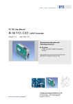
PZ184E User Manual E-802 Release: 1.0.0 Servo-Controller Submodule Date: 2006-10-26 This document describes the following Product(s): E-802.56 Servo-Controller Submodule, Revision BB-B or higher © Physik Instrumente (PI) GmbH & Co. KG Auf der Römerstr. 1 ⋅ 76228 Karlsruhe, Germany Tel. +49-721-4846-0 ⋅ Fax: +49-721-4846-299 [email protected] ⋅ www.pi.ws E-802.56 Servo-Control Submodule User Manual PZ184E Table of Contents 1 Safety Precautions ........................................................... 2 2 Introduction....................................................................... 3 3 Board Description............................................................. 4 3.1 Block Diagram.............................................................................. 4 3.2 Component Locations .................................................................. 5 3.3 Adjustment Potentiometers.......................................................... 5 3.4 Notch Filter Settings..................................................................... 6 3.5 Voltage Ranges and Over-Voltage Recognition Settings ............ 7 3.6 Test Points ................................................................................... 7 3.7 Solder Bridges ............................................................................. 8 3.8 Pinouts ......................................................................................... 9 3.8.1 Connector J1................................................................................ 9 3.8.2 Connector J2................................................................................ 9 4 Servo-Loop Calibration .................................................. 10 4.1 Equipment Needed for Calibration............................................. 10 4.2 Preparations............................................................................... 11 4.3 Zero-Point Adjustment ............................................................... 11 4.4 Static Gain Adjustment .............................................................. 11 4.5 Dynamic Calibration................................................................... 12 4.5.1 Finding Resonant Frequency and Setting Notch Filter .............. 12 4.5.2 Step Response Optimization ..................................................... 12 4.5.2.1 Empirical Method ....................................................................... 12 4.5.2.2 Advanced Tuning ....................................................................... 13 © Copyright 2006 by Physik Instrumente (PI) GmbH & Co. KG Release: 1.0.0 File:E-802UserPZ184E100.doc, 278528 Bytes Release 1.0.0 www.pi.ws Page 1 E-802.56 Servo-Control Submodule 1 User Manual PZ184E Safety Precautions CAUTION E-802 submodule boards are ESD-sensitive (electrostatic discharge sensitive) devices. Observe all precautions against static charge buildup before handling these devices. Avoid touching circuit components, pins and PCB traces. Discharge any static charge you may have on your body by briefly touching a conductive, grounded object before you touch any electronic assembly. Pose PCBs only on conductive surfaces, such as ESD-safe transport containers (envelopes, foam). Electronic subassemblies must always be kept and transported/shipped in conductive packaging. Make sure that no conductive particles of any kind (metallic dust or shavings, broken pencil leads, loose screws) get on the card. CAUTION Calibration of the controller the E-802 is a part of is done prior to delivery by the manufacturer. Do not adjust potentiometers unnecessarily. Only the zero point will have to be realigned from time to time to compensate for temperature changes. Further adjustments are not required as long as system components are not replaced or modified. Any calibration procedures are to be carried out by qualified authorized personnel only. CAUTION Some adjustment elements on the main board of the controller and on E-802 submodules are covered with sealing lacquer. Damage to the seal will void the warranty except in consultation with PI. Release 1.0.0 www.pi.ws Page 2 E-802.56 Servo-Control Submodule 2 User Manual PZ184E Introduction The E-802.56 is a small add-on printed circuit board (PCB) that processes the control signal for the power amplifier driving piezoelectric translators. Slew rate limitation, two notch filters and servo-control loop are all implemented on the E802.56. Fig. 1: E-802.56 servo-control submodule The servo-loop logic compares the control voltage input and the position sensor signal to generate the power amplifier input control signal. An analog proportionalintegral (P-I) algorithm is used. Slew rate limitation insures that the output signal slope does not exceed the following capability of the power amplifier. The notch filters are used to damp out oscillation at the resonant frequencies of the mechanics. In summary: • Slew rate limitation of output signals can be set within the range of 0.1 V/ms up to 1000 V/ms. Note that these values are only valid for the slew-rate-limitation circuit. The values for the complete system are lower due to limitations given by amplifier, notch filter etc. • P-I control performance, with individual setting of P- and I-terms, optionally Pterm and I-term can be used in parallel (default: P-term and I-term are connected in series) • Two notch filters allow for suppression of mechanical resonances, the second notch filter can be deactivated optionally. The filter frequency and quality for each filter can be adjusted separately. Note that both notch filters are only active in closed-loop operation (servo ON). • Servo function can be enabled/disabled via TTL signals (low=servo ON, high=servo OFF). Excellent long-term stability is accomplished by using exclusively low-tolerance / low-drift components. Residual errors in the range of 0.05% can be compensated with additional trimming components. The location of the E-802 in the device on which it is installed is indicated in the User Manual for that device. This manual only describes those functions and procedures specific to E-802.56s. For other E-802 models see the User Manuals PZ150E and PZ113E. Release 1.0.0 www.pi.ws Page 3 E-802.56 Servo-Control Submodule 3 Board Description 3.1 Block Diagram User Manual PZ184E The slew rate limiter is active even when the servo-mode TTL input line is at the servo-OFF level (open-loop operation), while the two notch filters are active only at the servo-ON level (closed-loop operation). Note: The servo ON-OFF “switch” is controlled by electrical signals from the board on which the submodule is installed. Fig. 2: E-802.56 Block diagram, P1 to P6 are designations of adjustment controls (see Sections 3.2 and 3.3 for details) Release 1.0.0 www.pi.ws Page 4 E-802.56 Servo-Control Submodule 3.2 User Manual PZ184E Component Locations P5 P4 S1 P6 P3 P2 P1 R10 R11 R9 Fig. 3: E-802.56 layout, component side Fig. 4: E-802.56 layout, solder side For element description see: P1 to P6 on p. 5, p. 6, p. 11 and p. 12 ff. S1 on p. 6 R9 to R11 on p. 7 TP1 and TP2 on p. 7 JP1, JP2 and JP3 on p. 8 For J1 and J2 pinouts see p. 9. 3.3 Adjustment Potentiometers The settings given below are the factory defaults for E-802.56s which are not integrated in other devices. For S1 details see Section 3.4. Potentiometer P1 P2 P3 P4 Function Default Setting Slew Rate Limitation Loop Gain (P-Term) Integration Time Constant (I-Term) Notch Filter 2 Frequency P5 Notch Filter 1 Frequency P6 Gain Fine Adjust slow (full CW) slow (full CCW) slow (full CCW) max. (full CW) in the range given by S1 (DIP 1 to 4 ON) Æ 130 Hz max. (full CW) in the range given by S1 (DIP 5 to 8 OFF) Æ 1.2 kHz center position Note: CW = clockwise, CCW = counter clockwise Release 1.0.0 www.pi.ws Page 5 E-802.56 Servo-Control Submodule 3.4 User Manual PZ184E Notch Filter Settings The notch filter frequencies can be set as follows: Notch filter 1: Use the mini DIP switches 5 to 8 of S1 to set the frequency range (see table below) and P5 for fine adjustment within the given range. Range Mini-DIP Switch Block S1 P5 full CCW = Min. P5 full CW = Max. (switch sliders shown in Number Notch Frequency in Hz Notch Frequency in Hz white) 1 380 1200 104 340 40 130 off on 2 off on 3 off on Note: CW = clockwise, CCW = counter clockwise Notch filter 2: Use the mini DIP switches 1 to 4 of S1 to set the frequency range (see table below) and P4 for fine adjustment within the given range. Range Mini-DIP Switch Block S1 P4 full CCW = Min. P4 full CW = Max. (switch sliders shown in Number Notch Frequency in Hz Notch Frequency in Hz white) 1 on 380 1200 104 340 40 130 off 2 on off 3 on off Note: CW = clockwise, CCW = counter clockwise If both notch filters are active, notch filter 1 should be set to the higher resonant frequency and notch filter 2 to the lower resonant frequency. If there is only one Release 1.0.0 www.pi.ws Page 6 E-802.56 Servo-Control Submodule User Manual PZ184E resonant frequency in your system, you can also set both notch filters to the same value. 3.5 Voltage Ranges and Over-Voltage Recognition Settings Nominal Voltage Range /V Actual Voltage Range / V R9 R10 R11 NV, 0 to100 -20 to +120 3.01 kΩ 14.0 kΩ 13.0 kΩ HI, -1000 to 0 -1120 to -3 4.02 kΩ 11.3 kΩ 14.7 kΩ HII, -750 to +250 -790 to +265 7.15 kΩ 10.5 kΩ 12.4 kΩ HIII, -500 to +500 -560 to +560 9.53 kΩ 11.0 kΩ 9.53 kΩ HIV, -250 to +750 -265 to +790 12.4 kΩ 10.5 kΩ 7.15 kΩ HV, 0 to +1000 +3 to +1120 14.7 kΩ 11.3 kΩ 4.02 kΩ Table 1. E-802.56 component substitution chart for voltage ranges and overvoltage recognition More precise adjustments are not possible here, as the reference voltage is derived from the operating voltage, which can vary by about 1% from the nominal value. The same tolerance has to be taken into account regarding over-voltage recognition. 3.6 Test Points Test point TP1, Slew Rate; Servo ON and OFF (for location see figure on p. 5) set required rise time using P1, watch PZT voltage and sensor values Typical curve at positive input step: U(TP1) 0V U(TP1) = f(t; P1) t After the rise time the input voltage must be reached. Note: This stage inverts the input signal. Release 1.0.0 www.pi.ws Page 7 E-802.56 Servo-Control Submodule User Manual PZ184E Test point TP2, comparison point, Servo ON only After settling, this voltage must be zero. Note: A permanent voltage indicates that somewhere in the servo-loop there is an undesireable limitation. (amplifier, PZT, sensor or controller) Typical curve at positive input signal step. U(TP2) 0V t 3.7 Solder Bridges The solder bridges JP1, JP2 and JP3 are located on the back of the board (see Fig. 5). Their functions and default settings are as follows: JP1 1-2 (default): 2-3: The on-target signal is available on J2 pin 2. That signal is TTL active-low, and switches when the distance between the current position and the target is within ±0.19% of the range. The VC/EC signal (servo ON/OFF; on J1 pin 5 and 6) is connected to J2 pin 2. JP2 1-2 (default): 2-3: Both notch filters are active Only notch filter 1 is active (switches 5 to 8 of S1 and P5) JP3 1-2 (default): 2-3: P-term and I-term are connected in series P-term and I-term are used in parallel Fig. 5: E-802.56 layout, solder side Release 1.0.0 www.pi.ws Page 8 E-802.56 Servo-Control Submodule 3.8 User Manual PZ184E Pinouts The connectors J1 and J2 of all E-802 versions are pin-compatible, except as noted. 3.8.1 3.8.2 Connector J1 (see Fig. 5 for location on the board and pin arrangement) Pin Signal Meaning 1 2 3 4 5 6 7 8 9 10 LED_K LED_A GND GND VC/EC VC/EC Actual value Actual value VEE VEE Overflow LED, cathode (-), normally 0 V = overflow Overflow LED, anode (+), normally always +5 V 0V 0V Set servo OFF/ON Set servo OFF/ON Current position (0-10 V) Current position (0-10V) -15 V -15 V Connector J2 (see Fig. 5 for location on the board and pin arrangement) Pin Signal 1 2 3 4 5 6 7 8 9 10 CTRL_OUT Servo-controlled output, -2 to +12 V ONT or VC/EC, depending on JP1 setting (see Section 3.7) COMMAND Target, 0-10 V OFL Overflow, TTL, active-low VCC +15 V VCC +15 V VEE -15 V VEE -15 V GND 0V GND 0V Release 1.0.0 www.pi.ws Page 9 E-802.56 Servo-Control Submodule 4 User Manual PZ184E Servo-Loop Calibration Static servo-loop calibration makes it possible to accurately drive the PZT system to absolute positions in closed-loop mode with an external analog control signal ranging from 0 to +10 volts. This signal can either be input directly, or it can be generated by computer-control electronics in the system (e.g. E-816 Computer Interface and Command Interpreter). Static servo calibration establishes the relationship between a sensor input of 10 V and the voltage necessary to drive the PZT to its nominal expansion. Dynamic servo-loop calibration optimizes step response and suppresses resonance, overshoot, and oscillation (see section Dynamic Calibration beginning on page 12). Dynamic performance of the PZT system is determined by the maximum output current of the amplifier and by the mechanical properties of the PZT-mechanics like moving mass, damping and resonant frequencies. In order to match the circuitry and the mechanical characteristics to achieve the desired performance, the system has to be adjusted for both static and dynamic operations. The full calibration and adjustment procedure includes adjustment of the zero point, sensor gain, slew rate and step response. All these basic adjustments are done in our lab before shipment. If PI has sufficient information about your application, your PZT system will be shipped ready for operation. Only the zero point will have to be realigned from time to time to compensate for temperature changes. Further adjustments are not required as long as system components are not replaced or modified. Since open-loop sensor zero and range adjustment does not involve the servocontrol module, it is described in detail in the other manuals accompanying this system. The PZT actuator has to be calibrated in conjunction with the individual device and submodule to which it is connected: both devices then belong together. Replacement of either one or the other requires new calibration run to get the specified system accuracy. 4.1 Equipment Needed for Calibration For adjustment of the zero-point, a voltmeter is required. Static displacement calibration requires an external expansion gauge with 0.1 µm resolution and a precision voltmeter. A special extension adapter may be required if your installation does not allow access to the potentiometers that need to be adjusted while the unit is in operation. Dynamic calibration procedures require an oscilloscope (a digital storage oscilloscope is recommended), frequency generator to output square and sine functions from 1 Hz to 1 kHz, an ohmmeter with a range from 0.1 to 100 k-ohm and, depending on the installation, a 32-pin extension adapter board to allow access to the trim potentiometers while the board is in operation. If the system is set up for computer control, it may be possible to substitute the wave generators, D-to-A and A-to-D converters there for some of the equipment mentioned above. Release 1.0.0 www.pi.ws Page 10 E-802.56 Servo-Control Submodule 4.2 User Manual PZ184E Preparations Mount the PZT actuator in exactly the same way and with the same load as during normal operations in the application. 4.3 Zero-Point Adjustment Correct zero-point adjustment allows the PZT to be used within the full displacement range without reaching the output voltage limits of the amplifier. A proper zero-point calibration ensures that in closed-loop operation the full output voltage swing of the amplifier can be used and prevents overflow conditions. Procedure: 1. Adjust the sensor zero point while servo mode is OFF as described in the manual for the controller (desktop unit, module or OEM board) on which the E802.56 is installed. 2. Set servo mode to SERVO ON and make sure that the control input voltage is set to the value (target position) which is to correspond to 0 V PZT operating voltage. Normally this control input voltage value is 0 V 1 . 3. Connect a voltmeter to the output socket for the PZT operating voltage. 4. Readjust the PZT operating voltage to 0 V using the ZERO potentiometer. 4.4 Static Gain Adjustment The objective of the static servo-loop adjustment is to ensure that the PZT actuator expands to its nominal expansion when the control signal input is 10 V. Preparations: An adjustable voltage source from 0 to +10.0000 V and a displacement gauge with 0.1 µm resolution is needed 2 . Procedure 1. Make sure that any DC-offset is set to zero or disabled (see main board manual). 2. Set SERVO ON mode. 3. Check whether the PZT oscillates. If it does, you can't miss hearing it, and dynamic gain adjustments have to be done prior to continuing with static gain adjustment. 4. Apply 0 V to the CONTROL INPUT. 5. Adjust the external position probe and set the expansion reading to zero. 6. Command a position equal to the nominal expansion (i.e. apply 10 V to the CONTROL INPUT). The external gauge should show the PZT at nominal expansion and the sensor monitor output should be 10 V. 7. To adjust the sensor monitor output to exactly 10.000 V use the P6 GAIN Fine Adjust potentiometer on the E-802.56 servo submodule. 8. To adjust the expansion without changing the sensor monitor output (servocontrol is on!) use the gain adjustment potentiometer on the E-801.x sensor module (E-801 is described in a separate manual). Repeat the last steps several times until stable results are achieved. 1 In some cases, e.g. with the E-651 controller/amplifier for closed-loop bender actuators, the PZT operating voltage has to be 0 V if the control input voltage is -5 V. 2 With bender actuators a non-contact measurement method must be applied. Release 1.0.0 www.pi.ws Page 11 E-802.56 Servo-Control Submodule 4.5 User Manual PZ184E Dynamic Calibration A summary of the equipment needed for calibration can be found in section 4.1 on page 10. 4.5.1 Finding Resonant Frequency and Setting Notch Filter Evaluate the resonant frequency of the actuator while installed at the operation site. For this purpose a square wave is applied to the input with servo-control set to OFF (≈10 Hz, 1 Vpp, use DC offset 0.5 V if bipolar). Connect the sensor monitor output with one channel of the oscilloscope and watch the step response. The resonant frequency of the system can be estimated by the induced oscillations. If, for example, the period of the oscillation is 3 ms, then the resonant frequency is 1/period length or 1/3 ms = 0.33 kHz or 330 Hz. Based on those estimations, the dimensioning of the notch filters can be found in the tables on page 6. 4.5.2 Step Response Optimization For dynamic operation, the step response of the mechanical system is important. The amount of damping and overshoot can be optimized by tuning the differential and integral term of the amplifier. For that purpose, either the empirical method (Section 4.5.2.1) or the advanced procedure described in Section 4.5.2.2 can be used. For the appropriate potentiometers and their factory default settings see p. 5. 4.5.2.1 Empirical Method 1. Mount the PZT exactly as it will be operated. 2. Set Servo ON. 3. Use a square wave function generator and supply the input with a square wave of 5 Vpp (if bipolar, set DC offset to 2.5 V) and a frequency of 5 to 10 Hz. 4. Connect an oscilloscope to the monitor output. 5. Adjust P2 until resonant frequencies become apparent. 6. Adjust P5 and P4 notch filter frequencies until the oscillation amplitudes become a minimum. 7. Adjust P2 and P3 alternating to optimize step response. The settling curve seen on the scope could look like one of the curves shown in Fig. 6: Case 1: Large overshoot, unstable Case 2: Optimal Case 3: Settling time too long Fig. 6: Sensor Monitor Signal Release 1.0.0 www.pi.ws Page 12 E-802.56 Servo-Control Submodule User Manual PZ184E 4.5.2.2 Advanced Tuning 1. Set potentiometer P1 (slew rate limitation) to CCW hard stop. 2. Set P2 (P-term) to a starting value. 3. Set P3 (I-term) to a starting value. 4. Power up the device and set SERVO ON. If you hear oscillation noise, set SERVO OFF immediately. Verify all values you have set. 5. Apply a square wave signal (10 Hz, 10 Vpp, 5 V Offset) to the input. 6. Turn potentiometer P3 (I-term) CW until a significant overshoot can be seen (2 to 5%). 7. Adjust P5 and P4 (notch filters) so that resonance effects and overshooting are optimally damped. 8. Depending on the application, set P3 either for optimized settling or to allow an overshoot of 5 to 10 %. The latter choice provides a larger bandwidth. 9. Turn P1 (slew rate limitation) CW until the wobble comes to a minimum without increasing the rise time significantly. 10. Apply a sine wave with variable frequency, 10 Vpp, 5 V offset. Check the sensor reading for amplitude and signal shape starting at 10 Hz up to the resonant frequency. If needed, repeat steps 8 and 9. If the bandwidth is too small, increase the I-term. (This also increases the overshoot amplitude for a step response.) If signal distortions are already noticeable well below the resonant frequency, decrease the I-term. Release 1.0.0 www.pi.ws Page 13