1
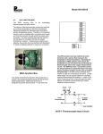
PZ 70E User Manual E-610 Release: 6.1.1 LVPZT Controller / Amplifier Date: 2010-02-16 This document describes the following product(s)*: T E-610.L0 TX X T LVPZT Controller (OEM) for Inductive Sensors E-610.S0 LVPZT Controller (OEM) for Strain Gauge Sensors E-610.00 LVPZT Amplifier (OEM), Single-channel TX X TX X T T * The E-610.C0 with capacitive sensor electronics is described in its own manual © Physik Instrumente (PI) GmbH & Co. KG Auf der Römerstr. 1 ⋅ 76228 Karlsruhe, Germany Tel. +49-721-4846-0 ⋅ Fax: +49-721-4846-299 [email protected] ⋅ www.pi.ws Declaration of Conformity according to ISO / IEC Guide 22 and EN 45014 Manufacturer: Manufacturer´s Address: Physik Instrumente (PI) GmbH & Co. KG Auf der Römerstrasse 1 D-76228 Karlsruhe, Germany The manufacturer hereby declares that the product Product Name: Model Numbers: Product Options: Low-Voltage Piezo Amplifier/ Controller Module E-610 all conforms to the following EMC Standards and normative documents: Electromagnetic Emission: EN 61000-6-3, EN 55011 Electromagnetic Immunity: EN 61000-6-1 U U U U Safety (Low Voltage Directive) : U U EN 61010-1 Electrical equipment which is intended to be integrated in other electrical equipment, only conforms to the cited EMC Standards and normative documents if the user ensures a compliant connection when implementing the total system. Possible necessary measures are installation of the component in a suitable shielded enclosure and usage of suitable connectors. September 2005 Karlsruhe, Germany Dr. Karl Spanner President Physik Instrumente (PI) GmbH & Co. KG is the owner of the following company names and trademarks: PI®, PIC®, PICMA®, PILine®, PIFOC®, PiezoWalk®, NEXACT®, NEXLINE®, NanoCube®, NanoAutomation® The following designations are protected company names or registered trademarks of third parties: Microsoft, Windows, LabView The products described in this document are in part protected by the following patents: Hyperbit™ (U.S. Patent 6,950,050) Copyright 1999–2010 by Physik Instrumente (PI) GmbH & Co. KG, Karlsruhe, Germany. The text, photographs and drawings in this manual enjoy copyright protection. With regard thereto, Physik Instrumente (PI) GmbH & Co. KG reserves all rights. Use of said text, photographs and drawings is permitted only in part and only upon citation of the source First printing 2010-02-16 Document Number PZ 70E, Eco, Bro, Release 6.1.1 E-610_User_PZ70E611.doc X X X X X X Subject to change without notice. This manual is superseded by any new release. The newest release is available for download at www.pi.ws (http://www.pi.ws). T T H H About this Document T Users of this Manual This manual is designed to help the reader to install and operate the E-610 LVPZT Controller / Amplifier. It assumes that the reader has a fundamental understanding of basic servo systems, as well as motion control concepts, piezoelectric drives and applicable safety procedures. The manual describes the physical specifications and dimensions of the E-610 LVPZT Controller / Amplifier as well as the installation procedures which are required to put the associated motion system into operation. This document is available as PDF file. Updated releases are available via FTP or email: contact your Physik Instrumente sales engineer or write [email protected]. X X X X X X X X HTU UTH Conventions The notes and symbols used in this manual have the following meanings: DANGER Indicates the presence of high voltage (> 50 V). Calls attention to a procedure, practice or condition which, if not correctly performed or adhered to, could result in injury or death. CAUTION Calls attention to a procedure, practice, or condition which, if not correctly performed or adhered to, could result in damage to equipment. NOTE Provides additional information or application hints. Related Documents The hardware components which might be delivered with E-610 LVPZT Controller / Amplifiers are described in their own manuals. Updated releases are available via FTP or email: contact your Physik Instrumente sales engineer or write [email protected]. X HTU X X X UTH E-801 User Manual, PZ117E E-802 User Manual, PZ150E The E-610 version with capacitive sensor processing is described in its own manual (PZ 72E). ! Contents 1 TU Introduction UT TU 1.1 1.2 UT TU TU UT TU Prescribed Use ...........................................................................3 General Description....................................................................4 TU UT UT 1.2.1 1.2.2 1.2.3 UT TU TU UT TU TU UT UT TU UT TU TU UT TU Main Module ...............................................................................7 Included Connector Set ..............................................................8 TU UT UT Operating Modes UT TU 3.1 3.2 3.3 3.4 3.5 9 UT UT TU TU UT TU TU UT TU UT TU UT Manual Offset Operation ............................................................9 External Operation .....................................................................9 External Operation with DC Offset ...........................................10 Open-Loop (Voltage-Controlled) Operation .............................10 Closed-Loop (Position-Controlled) Operation ..........................10 TU 4 UT UT TU UT TU UT TU UT Installation and Operation UT TU 4.1 4.2 4.3 UT TU TU UT TU TU UT 5 UT UT TU UT UT TU TU UT TU System Setup ........................................................................... 14 User Electronics and Sensor Monitor Signal ........................... 15 TU UT UT E-610 Calibration UT TU 5.1 5.2 5.3 5.4 5.5 5.6 UT TU TU UT TU TU UT TU UT TU UT TU UT UT UT TU UT TU UT TU UT TU UT Electronics UT TU 6.1 6.2 16 UT Equipment Needed for Calibration ...........................................16 Preparations .............................................................................16 LVDT Mechanical Zero-Point Adjustment ................................17 Electrical Zero-Point Calibration ...............................................17 Static Gain Adjustment .............................................................18 Dynamic Calibration .................................................................20 TU 6 12 UT General Instructions .................................................................12 E-610.00 Amplifier Modules .....................................................13 E-610 Models with Servo-Control.............................................13 TU 4.3.1 4.3.2 TU 7 UT 3 TU UT TU 2.1 2.2 TU TU Model Survey UT TU UT UT Safety Precautions .....................................................................5 UT 2 Servo-Control ............................................................................. 4 Applications ................................................................................ 4 Computer Control & Hyperbit™ ................................................. 5 TU 1.3 TU TU 3 UT 21 UT UT TU TU UT TU Block Diagram E-610.L0, E-610.S0 .........................................21 Front Panel ...............................................................................23 TU UT UT Contents 6.3 TU On-Board Components ............................................................23 UT TU UT 6.3.1 6.3.2 6.3.3 6.3.4 UT TU UT TU UT TU UT TU UT TU UT 6.4 TU Component Locations for E-610.00 ......................................... 23 Component Locations for E-610.L0 ......................................... 24 Component Locations for E-610.S0 ......................................... 24 Adjustment Elements ............................................................... 25 TU TU UT TU UT Submodules .............................................................................25 UT TU UT 6.4.1 6.4.2 7 TU UT TU TU UT TU TU Board and Amplifier Section (all models) .................................26 LVDT Sensor Processing (E-610.L0 only) ...............................27 SGS Sensor Processing (E-610.S0 only).................................28 TU UT TU TU UT TU TU UT 8 UT UT TU UT Dimensions UT TU 9 TU 9.1 9.2 9.3 9.4 30 UT System Connection Summary ..................................................30 32-Pin Main Connector.............................................................31 LEMO Pin Assignments ...........................................................32 Sensor Wiring Information ........................................................32 TU UT TU TU UT TU TU UT TU UT UT UT TU UT TU UT 9.4.1 9.4.2 10 29 UT Pin Assignments UT TU 26 UT 7.1 7.2 7.3 TU UT UT Technical Data UT TU E-802 Position Servo-Control Boards ...................................... 25 Sensor Excitation and Evaluation ............................................ 25 TU UT TU TU UT TU LVDT Sensor Description/Wiring ............................................. 32 SGS Sensor Description and Wiring ........................................ 33 TU UT UT Appendix: Piezoelectric Positioning Topics UT TU UT 35 10.1 Lifetime of PICMA® Actuators .................................................35 10.2 Sensors for Low-Voltage PZT Translators ...............................37 TU UT TU TU UT TU UT UT Introduction 1 1.1 Introduction Prescribed Use Based on their design and realization, the E-610 LVPZT Controller / Amplifiers are intended to drive capacitive loads, in the present case, piezoceramic actuators. The E-610 must not be used for applications other than stated in this manual, especially not for driving ohmic (resistive) or inductive loads. E610s with servo-controllers can be operated in closed-loop mode using the proper position sensors. Appropriate sensors are provided by PI and integrated in the mechanics according to the mechanics product specifications. Other sensors may be used as position sensors only with permission of PI. Observe the safety precautions given in this User Manual. E-610s conform to Measurement Category I (CAT I) and may not be used for Measurement Categories II, III or IV. Other use of the device (i.e. operation other than instructed in this Manual) may affect the safeguards provided. E-610s meet the following minimum specifications for operation * : TPF FPT Indoor use only Altitude up to 2000 m Ambient temperature from 5°C to 40°C Relative humidity up to 80% for temperatures up to 31°C, decreasing linearly to 50% relative humidity at 40°C Line voltage fluctuations of up to ±10% of the line voltage Transient overvoltages as typical for public power supply Note: The nominal level of the transient overvoltage is the standing surge voltage according to the overvoltage category II (IEC 60364-4-443). T T Degree of pollution: 2 * Any more stringent specifications in the Technical Data table are, of course, also met. TP www.pi.ws PT E-610 PZ 70E Release 6.1.1 Page 3 Introduction 1.2 General Description E-610.00 amplifiers and E-610.x0 amplifier/controller modules are designed to drive and to control low-voltage piezoelectric translators (LVPZTs). The E-610.00 is a single-channel amplifier with an average output power of 6 watts. The design is based on a controllable DC/DC converter, optimized for driving capacitive loads. E-610.L0 and E-610.S0 * are single-channel amplifiers and position controllers (LVPZT controller). TPF FPT All modules can be operated from a single DC voltage from 12 to 30 V. 1.2.1 Servo-Control Position feedback is the most effective way to suppress hysteresis and creeping effects; the piezo translators can then be controlled with an accuracy that is determined by the accuracy of the sensor used. Each module type supports a different type of position-control sensor: Strain gauge sensors (SGS), attached to the PZT stack or lever element Inductive sensors—either half-bridge sensors (IHB) or linear variable differential transformers (LVDT) Capacitive sensor versions, offering the finest possible resolution, are also available and are described in a separate manual. As an alternative, an externally processed sensor signal can be used. The analog input signal (control signal) can either drive the power amplifier input directly, or be fed through a slew-rate limiter and notch filter and/or a servo-control circuit first. The maximum output voltage ranges from -30 to +130 V so as to support the full extension capability of PI low-voltage translators. 1.2.2 Applications E-610 modules can be used for static and dynamic applications. High output stability and low noise assures stable * TP www.pi.ws PT E-610.C0 is described in a separate user manual, PZ 72E E-610 PZ 70E Release 6.1.1 Page 4 Introduction micropositioning. Because LVPZT translators have high capacitances, the amplifiers are designed to supply appropriate high peak currents for dynamic applications. Excellent linearity and stability allows the use of E-610 modules in precision measurement and control systems. Small size and compact design combined with excellent specifications make the E-610 series controller a preferred module for OEM users. Although the modules were designed to drive PZT positioning elements, they can also be used to drive other systems which require controlled operating voltages. 1.2.3 Computer Control & Hyperbit™ Computer control of an E-610 can be realized using a DACboard in a PC to generate the analog input signal. PI offers a LabVIEW driver set which can be used with certain D/A boards. This driver set is compatible with the PI General Command Set (GCS) LabVIEW driver set available for all newer controllers from PI. The Analog Controller LabVIEW Driver (E-500.ACD) is free of charge, but requires the LabVIEW environment from National Instruments for operation. In addition, PI’s patented Hyperbit™ technology for providing position resolution higher than that of the D/A board is available for purchase as an option (E-500.HCD). The PI Analog Controller and Hyperbit™ drivers support all D/A converter boards from National Instruments that are compatible with DAQmx8.3. LabVIEW compatibility is given from version 7.1 upwards. Instructions for downloading the Analog Controller drivers is given in a Technical Note. 1.3 Safety Precautions DANGER Read This Before Operation: T E-610 modules are OEM amplifiers generating HIGH VOLTAGES for driving LVPZTs. The output power may cause serious injuries. When working with these devices or using PZT products from other manufacturers we strongly advise you to follow the General Accident Prevention Regulations. www.pi.ws E-610 PZ 70E Release 6.1.1 Page 5 Introduction All work done with and on the modules described here requires adequate knowledge and training in handling High Voltages. Be sure to connect pin 32a/c to a Protective Ground! CAUTION ! Electrostatic Hazard T Electronic components are sensitive to electrostatic electricity. Take appropriate electrostatic protection measures when removing modules. Equipment Damage Most piezo stages that can be connected to this controller can be damaged or destroyed by uncontrolled oscillation near the mechanical resonant frequency. If you observe resonance while configuring your system, switch off power to the actuators concerned immediately and check the settings and servo-control parameters. www.pi.ws E-610 PZ 70E Release 6.1.1 Page 6 Model Survey 2 Model Survey 2.1 Main Module E-610 amplifier/controllers are designed as EURO-board plugin modules which can be installed in a desktop chassis as well as in a 19"-rack-mount chassis. The following different models are available: E-610.00 Single-board LVPZ amplifier module for OEM applications with integrated DC-DC power supply. This module consists of a mainboard with amplifier, power supply and heat sink. E-610.L0 Single-board LVPZT controller module for OEM applications consisting of an amplifier, a sensor supply (AC excitation) and processing circuit, including preamplifier, demodulator, different filters and a proportional-integral (P-I) controller for open-loop \ closed-loop operation. This module is mainly used with LVDT sensors. E-610.S0 Same main board as E-610.L0, but with a sensor excitation and processing submodule for strain gauge sensors (SGS). The E-610.C0, the capacitive sensor version, is described in a separate manual. www.pi.ws E-610 PZ 70E Release 6.1.1 Page 7 Model Survey 2.2 Included Connector Set Included with the E-610 module is a connector set designed to facilitate operating it in a user-provided housing. This set includes the following items: Solderable socket matching the 32-pin main connector, designed for installation completely inside the user housing. Because the connector standard includes types with more pins, the 32 pins used are all carry even number designations and are in rows “a” and “c”. Panel-mount coaxial socket (Lemo ERN.00.250.CTL) designed for bringing the PZT drive-voltage lines (on the 32-pin main connector) outside the user housing and interfacing with PI actuators and stages 4-conductor, panel-mount socket (Lemo ERA.0S.304.CLL) designed for bringing the sensor excitation and readout lines (on the main connector) outside the user housing and interfacing with PI actuators and stages (not included with amplifier-only version, E-610.00) Fig. 1: Included connectors See “LEMO Pin Assignments”, p. 32 for pinouts. X www.pi.ws X X X E-610 PZ 70E Release 6.1.1 Page 8 Operating Modes 3 Operating Modes All units can be operated as simple power amplifiers, i.e. in voltage-controlled mode, where the PZT output voltage depends directly on input control voltage and DC offset potentiometer setting. This is also known as open-loop or servo-off operation. Units with servo-controller (i.e. all except E-610.00) can also be operated in position-controlled mode. In position-controlled mode, the control input plus DC offset is interpreted as a target position, and the signal from the position sensor is used as input to a servo-control feedback loop. Position-controlled (closed-loop) mode permits elimination of drift and hysteresis. T T In both open- and closed-loop modes, the units can be operated manually or via an external analog control input voltage, or by a combination of the two. NOTE—Actuator Lifetime The sum of input control voltage and DC-offset potentiometer setting should not exceed the -2 to 12 V range. In open-loop operation, -2 to 12 V control input will result in -20 to 120 V piezo output voltage. -3 to 13 V control input are possible and will result in -30 to 130 V output voltage, but working with increased output voltage will decrease actuator lifetime. See “Lifetime of PICMA® Actuators” on p. 35 for details. X X 3.1 X X Manual Offset Operation In manual operation, the target voltage or position is controlled manually with an external 10 kΩ DC-offset potentiometer (not included). This potentiometer must be connected to pins 12a (-10 V), 14a (GND), and the wiper to pin 12c, and it must be activated with jumper J3 in position 1-2. 3.2 External Operation For external operation, the offset potentiometer should be deactivated (jumper J3) and the target voltage or position is controlled by an external DC signal of -2 to 12 V. www.pi.ws E-610 PZ 70E Release 6.1.1 Page 9 Operating Modes See “Computer Control & Hyperbit™,” p. 5, for information on PI support of external operation with a DAC card in a PC. X 3.3 X X X External Operation with DC Offset For external operation with offset, the offset potentiometer (or equivalent) is activated and attached with jumper J3 in position 1-2 and an external DC signal is used on Control IN. The position of the potentiometer (wiper voltage) is added to the analog control input signal. The result must be in the -2 to +12 V range. With, for example, an offset setting of 5 V, the control input could range from -7 to +7 V. 3.4 Open-Loop (Voltage-Controlled) Operation In open-loop mode, the position servo-control circuit is bypassed and the system works like an amplifier. In this mode, the PZT drive voltage is proportional to the control signal input in combination with the DC offset potentiometer, if installed and activated. (The sensor electronics works independently and outputs the current piezo position on “sensor monitor” even though that value is not used internally in open-loop mode, provided a sensor is connected to the appropriate main connector pins). The PZT output voltage can be monitored either directly (in parallel with the PZT) or on main connector pin 8a, which carries a high-impedance output of 1/100th the voltage of the PZT. All modules have the analog input on pin 10c. With DC offset at zero, the nominal input voltage range is -2 to +12 V for a -20 to 120 V output voltage range. If the input signal available is bipolar, set the external DC-offset potentiometer (or an equivalent divider) to an appropriate setting. When set, for example, to provide a 50 V output with 0 V input, a control input in the -5 to +5 V range will cover an output range of 0 to 100 V. 3.5 Closed-Loop (Position-Controlled) Operation All E-610 models except the E-610.00 have position-sensor processing electronics for closed-loop operation. Closed-loop www.pi.ws E-610 PZ 70E Release 6.1.1 Page 10 Operating Modes operation differs from open-loop operation in that the analog control input (plus any DC offset) is interpreted as a target position rather than a target voltage. Depending on the sensor type, different sensor electronics are required: LVDT sensors require AC excitation and the sensor processing add-on board, E-801.2x, is installed. Strain gauge sensors work preferably with DC signals and use the E-801.1x add-on board instead. Closed-loop operation offers both drift-free and hysteresis-free positioning. The servo-control electronics is implemented on a plug-in submodule, the E-802. See the E-802 User Manual for details. In position-controlled mode, it is the output of the P-I (proportional integrated) controller that is used as input to the amplifier. The piezo position is refined until the final position is reached. In this controlled mode, the PZT position is directly proportional to the module’s input signal while the PZT supply voltage may not be. The operating voltage for the PZT must remain in the range from -30 to +130 V. If one of these limits is reached and the resulting expansion of the PZT does match that specified by the control signal, a TTL signal (overflow) is output on pin 26a. PI’s standard calibration procedure assures that the PZT reaches its nominal expansion value when the control input signal is +10 V. To enable closed-loop mode do both of the following: 1. Set jumpers J1 and J2 on the main board to positions 2-3. 2. Connect pin 28a to pin 20a/c (Test GND). If pin 28a is not connected, then the unit works in voltage-controlled (open-loop) mode. The notch filter and slew-rate limiter are also active. (Disabling servo mode will not always deactivate them. See the E-802 User Manual for details.) www.pi.ws E-610 PZ 70E Release 6.1.1 Page 11 Installation and Operation 4 Installation and Operation 4.1 General Instructions DANGER Read This Before Operation: T E-610 modules are OEM amplifiers generating HIGH VOLTAGES for driving LVPZTs. The output power may cause serious injuries. When working with these devices or using PZT products from other manufacturers we strongly advise you to follow the General Accident Prevention Regulations. All work done with and on the modules described here requires adequate knowledge and training in handling High Voltages. Be sure to connect pin 32a/c to a Protective Ground! CAUTION: Equipment Damage Most piezo stages that can be connected to this controller can be damaged or destroyed by uncontrolled oscillation near the mechanical resonant frequency. If you observe resonance while configuring your system, switch off power to the actuators concerned immediately and check the settings and servo-control parameters. Connector descriptions and pinouts are given at the end of this manual. All inputs and outputs are available on the main connector (p. 31). X X On the main board of the E-610 modules a DC-DC converter is installed with a 12 to 30 VDC input voltage range. The converter generates -37 and +137 V for the power amplifier and +/-15 V for the sensor and servo-controller (if present). NOTE - When powering up the module, the DC-DC converter needs a peak current of about 1.5 A to start oscillating. The power supply should have a buffer capacitor, or the www.pi.ws E-610 PZ 70E Release 6.1.1 Page 12 ! Installation and Operation external power supply should be able to supply the 1.5 A for at least 1 second. - The inputs and outputs of the DC-DC converter are not connected internally. Using a unipolar power supply, we recommend connecting the negative supply at pin 18a,c with the Test GND at pin 20a,c. This provides a defined GND level and helps to minimize noise. 4.2 E-610.00 Amplifier Modules Make sure jumpers J1 and J2 on the main module are set to position 1-2 to disable the servo-control elements which are not present on this version. Optionally connect an external 10 kohm potentiometer to 12a, 12c and GND and make sure it is activated (J3 in position 1-2, see block diagram in Section 6). X X Supply the board with the DC power in the 12 to 30 V range at pins 16a/c and 18a/c. The green power-on LED on the base board should light up. Check the LVPZT output voltage between pin 2a/c and 4a/c main connector without an LVPZT connected. If you have connected the optional external potentiometer to offset the control input range, then this can be used to check the output voltage. Varying the offset from 0 to +10 V should make the output vary from 0 to +100 V. If no external potentiometer is connected, drive the analog input (pin 10c) with a control voltage in the range of -2 to +12 V. The corresponding output should be -20 to +120 V. 4.3 E-610 Models with Servo-Control NOTE: Calibration If your unit is delivered with the PZT actuator that it is to drive, it will have been configured and calibrated with that actuator at the factory. Be careful not to interchange actuators and controllers if you have more than one. It should not be necessary to recalibrate the system unless hardware changes are made. It may be necessary to adjust the zero point if operating conditions such as load or temperature change greatly. For details see section “E610 Calibration” beginning on page 16. X X www.pi.ws X X E-610 PZ 70E Release 6.1.1 Page 13 Installation and Operation 4.3.1 System Setup The first step in installation is to connect the actuator and sensor. Sensors are connected to pins 24c, 26c, 28c, 30c (for details see the sensor wiring section beginning on page 32). You can use the included 4-conductor, panel-mount Lemo socket for interfacing to a matching connector on the mechanics (see p. 32 for details). Also connect the control input signal and/or offset potentiometer (if any), as well as any monitoring instruments you want to use. X X X X The second step is to select the operating mode—either voltage-controlled (open-loop) or position-controlled (closedloop). Connect pin 28a on the main connector to pin 14ac (GND) to enable closed-loop (servo ON) mode or leave pin 28a open for open-loop (servo OFF) mode. Note that with the E802.55 model servo-control submodules, the notch filter and slew rate limiter stay on in open-loop, unless the submodule is jumpered out of the circuit (see block diagrams, p. 21 ff.). See the E-802 User Manual for details. X X Operating the modules you should consider the following items: Depending on the sensor type (E-610 model type), appropriate sensor processing is provided (DC for SGS, AC for LVDT): www.pi.ws E-610.L0 Supports LVDT sensor. Sensor processing is implemented on the E-801 submodule, which is described in detail in a separate User Manual. On the E-801, AC signals from the sensor are amplified in a dual stage preamplifier, settable between medium- and high-gain to optimize piezo performance. An analog output signal is available at the output of the demodulator which is directly proportional to the piezo expansion. This signal can be finetuned as to amplitude and zero point with trim pots See the E-801 User Manual for details. E-610.S0 Supports SGS sensor. Sensor processing is implemented on the E-801 submodule, which is described in detail in a separate User Manual. One the E-801, DC signals are amplified in a preamplifier stage which outputs an analog signal directly proportional to the PZT expansion. Again, gain and zero point can be adjusted with trim pots. E-610 PZ 70E Release 6.1.1 Page 14 Installation and Operation With 0 DC offset and servo-control ON, an analog input signal of +10 V should cause the PZT to expand to its nominal value. At zero input, the sensor monitor voltage at main connector 22a should also measure zero. If not, perform the Electrical ZeroPoint Calibration described on p. 17) to correct it. At the nominal PZT expansion, pin 22a should measure around +10 V. X X X X In cases where the piezo drives a mechanical system up to its mechanical resonance, the additional induced phase shift could result in unstable operation if the feedback loop were closed. To suppress such critical resonance an optional notch filter can be activated on the main board. By default, it is bridged by zeroohm resistor, R35. Most dynamic applications require the power amplifier to deliver a short peak current higher than the average value. Because of the limited power of the transistors, this peak is limited to about 5 ms in length. After this time the current decreases to the average value. There may be cases where the control signal calls for an even higher peak current, but the required current cannot be supplied. To avoid such non-linearities, a slew rate limitation is added to the control circuit. This feature guarantees wide signal bandwidth without overdriving the power amplifier. There are additional potentiometers for optimizing closed-loop operation. See the “E-610 Calibration” Section for details. X X 4.3.2 User Electronics and Sensor Monitor Signal If you are connecting your own electronics to the sensor monitor signal (main connector, p. 32), make sure it has sufficient input capacitance to eliminate high-frequency interference. X X It may be necessary to add a 4.7 nF (ceramic NP0 or COC type) to the input connector. Use shielded cable if possible, otherwise make sure the lead pair is tightly twisted. www.pi.ws Fig. 2: Electronics on Sensor Monitor line with required input capacitance E-610 PZ 70E Release 6.1.1 Page 15 E-610 Calibration 5 E-610 Calibration All piezo positioning systems with a PZT translator are delivered with performance test documents to verify the system performance. The servo controller is calibrated prior to shipment in our labs. Normally there is no need for the customer to perform a full calibration. Only if the PZT, the sensor, extension cable or the mechanical setup is changed, may new calibration be necessary. The system is ready for operation upon delivery. PZTs and their assigned controllers are matched and should be considered as a unit. The serial numbers of the PZTs installed are marked on the individual modules. Some calibration steps, however, must be performed in any case, either to compensate different loading and mounting details or to tune dynamic behavior for stable operation. NOTE For some calibration steps the heat sink (cover plate) has to be removed to make certain test points or components on the add-on modules available. 5.1 Equipment Needed for Calibration Zero-point adjustment requires a voltmeter. Static displacement calibration requires an external expansion gauge with appropriate resolution (e.g. 0.01 µm for a P-841.30 actuator) and a precision voltmeter. Access to adjustment elements on the submodules while the system is in operation is necessary, so an extension connector may be required. 5.2 Preparations Mount the PZT actuator in the same way and with the same load as during normal operations in the application. In multi-axis systems, make sure the PZTs are always connected to the same controller modules. www.pi.ws E-610 PZ 70E Release 6.1.1 Page 16 E-610 Calibration 5.3 LVDT Mechanical Zero-Point Adjustment LVDT sensors have a mechanical zero point adjustment. SGS sensors are permanently affixed and cannot be shifted mechanically. Models connected to LVDT sensors also may need to have the mechanical zero-point of the sensor adjusted. LVDT sensor readout is based on differential measurement of the inductive excitation of two secondary coils with a common, moving, ferrite core. The first step of the alignment procedure is to balance the bridge by moving the ferrite core (probe) to the zero position. To verify the balance of the bridge, display the sinusoidal voltages on connector X18 pin 9 (main connector pin 26c) and pin 4 (main connector 28c) on a 2-channel oscilloscope. If the bridge is balanced properly, both sine curves have the same amplitude and phase. If there is any deviation, move the LVDT mechanically until both curves become identical. 5.4 Electrical Zero-Point Calibration Electrical zero-point calibration has the goal of making the point of zero expansion coincide with the point of zero control input voltage. There might be some small deviation of the electrical zero-point caused by thermal drift or changes in mechanical loading. Let the system warm up for several minutes before setting the zero point. If the electrical zero point is adjusted properly, the full output voltage range of the amplifier can be used and only a small offset is required to get a zero reading. This prevents overflow conditions from arising due to improper match of actual and desired expansion windows. The adjustment procedure is as follows (see section “On-Board Components” on p. 23 for location of adjustment elements): X X 1 www.pi.ws X X Before powering up the system, make sure the PZT actuator is mounted in the same way and with the same load as during normal operations in the application E-610 PZ 70E Release 6.1.1 Page 17 E-610 Calibration 2 Make sure that jumper J4 is correctly set: 1-2 for SGS, 2-3 for LVDT. 3 Make sure the control input is 0 V. 4 If there is a DC-Offset potentiometer installed and activated, make sure it is in the 0 V position (usually full counterclockwise). 5 Connect +15 V and GND to the E-610 module. Note that for starting the module, a current of at least 1500 mA is required; otherwise the internal oscillator will not start. Only 400 mA are required after start up. 6 If you use your own LVDT sensors, adjust the sensor mechanical zero position (LVDT core position). For details see the section 5.3 on page 17. X X X X 7 Set the module to voltage-controlled (servo OFF, openloop: J1, J2 in positions 1-2). 8 Now exercise the PZT over the nominal expansion range by applying analog signals 0-10 V to pin 10c. Then set the PZT to 0 with 0 V at 10c. 9 Read the voltage at pin 22a (sensor monitor). Adjust the P406 zero potentiometer so that the reading is in the range of 0 to +1 V (+1 V is recommended for increased actuator lifetime). The zero point is now close enough to allow going into servo mode. 10 Set the unit to servo ON. 11 Again using the zero potentiometer, adjust until the PZT monitor out (or the PZT voltage itself) is 0 V. Because servo-control is now active, the sensor monitor signal will not change: the servo-controller will cause PZT actuator motion to maintain the position. 5.5 Static Gain Adjustment It should only be necessary to readjust the static gain if system components have been exchanged or altered. Before doing so, reading the detailed description of the sensor-processing system is recommended (E-801 Sensor Submodule User Manual). The objective of static gain adjustment is to ensure that the PZT actuator expands to its nominal expansion when a control www.pi.ws E-610 PZ 70E Release 6.1.1 Page 18 E-610 Calibration signal input of 10 V is applied (amplifier module DC-offset set to 0). The zero-point must be appropriately set before the static gain adjustment can be performed. This is an iterative process. The static gain adjustment procedure is as follows (location of adjustment elements on the submodules is described in the E801 Sensor Submodule and the E-802 Servo Submodule User Manuals; location of mainboard elements in Section 6.3 beginning on p. 23 ): X X X X 1 Before powering up the system, make sure the PZT actuator is mounted in the same way and with the same load as during normal operations in the application. 2 Mount an external gauge to measure the PZT displacement. (with PZT power amplifier powered down, the external gauge should read 0; if it does not, note the offset and subtract it from subsequent readings) 3 Set servo mode to SERVO OFF (J1 and J2 in pos. 1-2). 4 Make sure the DC-Offset potentiometer (if installed and activated) is still set to zero. 5 Set control input to 0 V. 6 Connect +15 V and GND to the E-610 module. NOTE For starting the module, a current of at least 1500 mA is required; otherwise the internal oscillator will not start. Only 400 mA are required after start up. 7 Scan the control input voltage from 0 V to +10 V and read the PZT displacement using the external gauge. With +10 V the external gauge should show the PZT at about nominal expansion. Adjust with the sensor gain trim potentiometer (see Fig. 3 and component maps beginning on page 23). Sensor gain is now close enough to allow switching servo ON. X X 8 www.pi.ws X X Set servo ON. E-610 PZ 70E Release 6.1.1 Page 19 E-610 Calibration 9 Adjust the sensor monitor signal to exactly 10.000 V using the gain adjustment potentiometer on the E-802 servo submodule (different versions of this submodule exist, see the E-802 User Manual for gain adjustment on your unit). 10 Adjust the PZT position to the nominal expansion value using the sensor gain adjustment. Now, because servo ON, the sensor monitor value will not change! 11 Repeat the last two steps until you get stable readings. If the Gain settings have been changed, the zero-point adjustment starting with section 5.4 should be repeated, and then the static gain rechecked. X X Sensor gain adjustment Fig. 3: Sensor gain on E-801 sensor excitation and readout submodule. Most versions in circulation have the sensor gain adjustment as shown. See the E-801 User manual for more details. 5.6 Dynamic Calibration Dynamic performance of the PZT system is determined by the maximum output current of the amplifier and by the mechanical properties of the PZT mechanics, like moving mass, damping and resonant frequencies. Dynamic calibration optimizes step response and suppresses resonance, overshoot, and oscillation. Those servo-loop, notch filter and slew-rate limitation setting procedures are all described in detail in the E802 Servo-Control Submodule User Manual. www.pi.ws E-610 PZ 70E Release 6.1.1 Page 20 Electronics 6 Electronics The basic circuit design of the amplifier and controller modules is shown in the drawings on the following pages. Input signals at main connector pin 10c and the signal from the external DCoffset potentiometer are combined in the preamplifier stage. Depending on the model/configuration, the resultant signal will be used either as input for the amplifier or as input signal for the position servo-control circuit. 6.1 Block Diagram E-610.L0, E-610.S0 For more detailed information on the E-801 sensor processing submodules, see the E-801 User manual. For more detailed information on the E-802 servo-control submodules, see the E-802 User Manual. www.pi.ws E-610 PZ 70E Release 6.1.1 Page 21 Electronics *External Servo ON/OFF (pin 28a) is only effective if J1/J2 are properly set. In older E802 versions, 28a switches notch filter and slew-rate limiter as well as servo-control. Fig. 4: E-610.L0, E-610.S0. Note that the control input on pin 10c can be -3 to 13 V which will result in -30 to 130 V output voltage, but working with increased output voltage will decrease actuator lifetime. See “Lifetime of PICMA® Actuators” on p. 35 for details. X www.pi.ws E-610 PZ 70E Release 6.1.1 X X X Page 22 Electronics 6.2 Front Panel The green LED indicates that the module is powered up and in operation. The yellow LED lights when an overflow condition occurs: i.e. an attempt to drive the PZT voltage under -30 or over +130 V. 6.3 On-Board Components 6.3.1 Component Locations for E-610.00 Fig. 5: Component Locations for E-610.00 www.pi.ws E-610 PZ 70E Release 6.1.1 Page 23 Electronics 6.3.2 Component Locations for E-610.L0 Fig. 6: E-610.L0 layout: older equipment may have other submodule versions: see the submodule User Manuals for details 6.3.3 Component Locations for E-610.S0 Fig. 7: E-610.S0 layout: older equipment may have other submodule versions: see the submodule User Manuals for details www.pi.ws E-610 PZ 70E Release 6.1.1 Page 24 Electronics 6.3.4 Adjustment Elements J1 & J2: T J3: T T T 1-2 (both): bypass E-802 (servo-control, slew rate limiter and notch filter) completely 2-3 (both): use E-802 1-2: external potentiometer activated 2-3: external potentiometer deactivated 1-2: DC sensor excitation (SGS sensors only) 2-3: AC sensor excitation (required for LVDTs) T J4: T T 6.4 T T T Submodules Servo-control and LVDT/SGS sensor evaluation and excitation functions are implemented in plug-in submodules. E-801 submodules interface to these sensors, while E-802 modules perform servo-control. It should not be necessary to remove or replace the submodules, but if you ever do so, note that the submodule component sides face each other as shown above. 6.4.1 E-802 Position Servo-Control Boards The E-802 submodule processes the control signal for the amplifier driving the piezoelectric translators. Slew rate limitation, notch filter and servo-control loop are all implemented on the E-802. The servo-loop logic compares the control voltage input (target) and the sensor signal (actual position) to generate the amplifier control signal using an analog proportional-integral (P-I) algorithm. For calibration procedures, see Section 5 and the E-802 ServoControl Submodule User Manual. X X 6.4.2 Sensor Excitation and Evaluation On all but the amplifier-only version, an E-801 submodule provides sensor excitation and readout. E-801.1x submodules provide DC sensor excitation and can be used with strain gauge sensors (SGS) only. E-801.2x submodules provide AC sensor excitation and are primarily for LVDT sensors, although they can be used with SGS sensors if necessary. Should you ever need to make any adjustments on the sensor submodules, refer to the E-801 User manual for more details. www.pi.ws E-610 PZ 70E Release 6.1.1 Page 25 Technical Data 7 Technical Data 7.1 Board and Amplifier Section (all models) Channels: Single-channel Output voltage range: -30 to +130 V* Peak output current: 140 mA (5 ms max.) Max. average output current: 60 mA Max. average output power: 6 W (with forced-air cooling > 10 m3/h) Control input voltage range: -2 to 12 V*, shiftable with DC offset Voltage gain: 10+/-1% Input impedance: > 100 kΩ DC-offset adjustment range: 100 volts wide, adds 0 to +10 V to Control In Bandwidth: See frequency response curves (Figure below) Ripple of Uout: 20 mVpp at low frequencies 40 mVpp (spikes) at 30 kHz Input connector: BNC ( E-610.00 only ) PZT output connector (not on board) Panel-mount, 2-conductor LEMO ERN.00.250.CTL included for user installation Dimensions: EURO-board: 160 x 100 x 35.6 mm Main connector: 32 pin DIN 41612 D Eurocard connector * -2 to 12 V is the recommended control input range, resulting in -20 to 120 V piezo output voltage. -3 to 13 V control input are possible and will result in -30 to 130 V output voltage, but working with increased output voltage will decrease actuator lifetime. See “Lifetime of PICMA® Actuators” on p. 35 for details. X X X X Power Requirements: Max. power consumption: 15 W Operating voltage range: 12 to 30 VDC, max. ripple 50 mV pp (15 V recommended) Operating current: 2 A max. Front-Panel LEDs www.pi.ws Green Power on Yellow Overflow (PZT out > 130 V or < -30 V) E-610 PZ 70E Release 6.1.1 Page 26 Technical Data Fig. 8: E-610 open-loop frequency response with various PZT loads. Values shown are capacitance in μF. 7.2 LVDT Sensor Processing (E-610.L0 only) Implemented on E-801.2x sensor processing submodule; see E-801 User Manual for more details. www.pi.ws Sensor type: LVDT, Inductive probes Sensor excitation: 10 Vpp standard, max 25 Vpp 20 to 20,000 Hz, 50 mA Preamplifier gain: 10, 100, selectable Sensor monitor output: 0 to +10 V for nominal expansion Display output: 0 to max. 2 V, adjustable Sensor connector (not on board) Panel-mount, 4-conductor LEMO ERA.0S.304.CLL included for user installation E-610 PZ 70E Release 6.1.1 Page 27 Technical Data 7.3 SGS Sensor Processing (E-610.S0 only) Implemented on E-801.1x sensor processing submodule; see E-801 User Manual for more details. www.pi.ws Sensor type: Strain gauge (SGS) Sensor excitation: 5 VDC, adjustable Low pass cut off frequency: 300 Hz (Selectable 1 kHz/3 kHz) Sensor monitor output: 0 to +10 V for nominal expansion Display output: 0 to max 2 V adjustable Sensor connector (not on board) Panel-mount, 4-conductor LEMO ERA.0S.304.CLL included for user installation E-610 PZ 70E Release 6.1.1 Page 28 Dimensions 8 Dimensions Fig. 9: E-610.00, E-610.S0 and E-610.L0 dimensions in millimeters www.pi.ws E-610 PZ 70E Release 6.1.1 Page 29 Pin Assignments 9 Pin Assignments 9.1 System Connection Summary For operation, at least the following elements must be connected: Main Connector Supply power, 12-30 VDC PZT out PZT GND Sensor excitation Sensor readout Control in DC-offset pot GND Protective GND Lemo Only for Connector (if used) + 16a&c; – 18a&c 2 a&c 4a&c 24c, 30c (GND) pin 1, pin 4 26c, 28c pin 2, pin 3 10c 12a 12c & 14ac 22c, 20a&c, 14a&c 32a&c closed-loop closed-loop * * *The DC-offset pot may be missing (deactivate with X4) or the Control In signal shorted, but not both. www.pi.ws E-610 PZ 70E Release 6.1.1 Page 30 Pin Assignments 9.2 32-Pin Main Connector Because the DIN 41612 connector standard includes types with more pins, the 32 pins of the “D” version all carry even number designations and are in rows “a” and “c”. PZT output, LEMO center* PZT GND, LEMO shield* nc a 2 c PZT output* a 4 c PZT GND* a 6 c nc Monitor PZT out (100:1) Internal use a 8 c Internal use a 10 c Amplifier input 10 kOhm pot (-10 V) a 12 c Pot wiper 10 kOhm pot (GND) & test GND +VCC supply a 14 c a 16 c Pot 10 kOhm (GND) & test GND +VCC supply -VCC supply a 18 c Test GND a 20 c Sensor monitor 1 a 22 c Display sensor (adjust.) Overflow (TTL) a 24 c a 26 c Servo OFF/ON select a 28 c Internal use a 30 c a 32 c TPF FPT X1X X1X X1X X1X Protective GND -VCC supply (connect to 20c for minimum noise) Test GND Sensor monitor GND, Test GND Sensor excitation, see wiring diagram, 4-line LEMO pin 1* Sensor readout signal, see wiring diagram, connect to 4line LEMO pin 2* Sensor readout signal, see wiring diagram, LEMO pin 3* Sensor excitation GND, see wiring diagram, LEMO pin 4* Protective GND *Separate panel-mount LEMO socket(s) are included which can be used to bring the stage/actuator connection line outside the user housing and interface to PI actuators/stages. See Section 9.3 for details. X 1 TP www.pi.ws PT X Not applicable for E-610.00 amplifier-only versions E-610 PZ 70E Release 6.1.1 Page 31 Pin Assignments 9.3 LEMO Pin Assignments If desired, the included panel-mount LEMO socket(s) can be used to interface to plug(s) on the stage or actuator. If used, they should be wired as indicated below. Use coaxial/shielded cable and keep runs as short as possible. Coaxial- LEMO Connector, ERN.00.250.CTL For PZT output drive voltage: Center from main connector pin 2 a or c, Shield from main connector pin 4 a or c 4-conductor LEMO ERA.0S.304.CLL: For SGS or LVDT sensor connection (not with E-610.00): pin 1 pin 2 pin 3 pin 4 shield 9.4 from main connector pin 24c, sensor excitation from main connector pin 26c, sensor signal from main connector pin 28c, sensor signal from main connector pin 30c, sensor excitation GND from main connector pin 22c Sensor Wiring Information 9.4.1 LVDT Sensor Description/Wiring LVDT sensor excitation and signal processing is implemented on an E-801 submodule. Consult the E-801 User Manual for details and information on the various E-801 versions in use. Sensors working on the principle of LVDTs have usually a bobbin with a primary winding, two secondary windings and a moving core. If an AC current is applied to the primary winding, it produces a magnetic field which is concentrated by the soft iron or ferrite core. The magnetic field then passes through the two secondary windings and induces a voltage in each. If the core is moved from the central position one secondary winding receives more magnetic flux than the other thus the induced voltages are different and proportional to the movement. LVDT transducers normally operate at 3 to 5 Vrms and at frequencies between 1 and 20 kHz and have a typical current consumption between 10 and 50 mA. The output signal from an LVDT can be expressed as a sensitivity in mV output voltage per volts of the supply voltage and per millimeter displacement. Typical LVDT output sensitivity is in the range of about 100 to 250 mV/V/mm www.pi.ws E-610 PZ 70E Release 6.1.1 Page 32 Pin Assignments depending on the type. LVDTs have to be used in conjunction with E-610.L0 modules. Fig. 10: Linear Variable Differential Transformer Type SMI and M6DI 9.4.2 SGS Sensor Description and Wiring SGS sensor excitation and signal processing is implemented on an E-801 submodule. Consult the E-801 User Manual for details and information on the various E-801 versions in use. Strain gauge sensors can be used to measure the expansion of piezo translators. In most of the standard products, two strain gauges are attached on opposite sides of the ceramic stack. Together with two bridge completion resistors, the strain gauges are wired in diagonal positions to form a Wheatstone bridge. The bridge is balanced if all four elements have the same resistance. Small tolerances can be compensated in the electronics. The resistance of the strain gauges depends on the expansion of the piezo elements. The measuring bridge outputs a signal of about 1 mV / V at full expansion. The bridge completion www.pi.ws E-610 PZ 70E Release 6.1.1 Page 33 Pin Assignments resistors are mounted inside the LVPZT casing to minimize cable influence and temperature sensitivity. Only in some very small elements, where no space is available, are the resistors placed on the controller board (see jumper J401). All LVPZTs having 60 µm expansion or more, two strain gauges and resistors are connected in series to measure with higher accuracy. Some special strain gauges with four active elements (two Poisson gauges) are available on request. Correct wiring of the strain gauges can be tested easily by measuring the total bridge resistance at the LEMO connector between pin 1,4 (supply) and pin 2,3 (outputs). The value should be about 700 ohm for smaller LVPZTs and about 1400 ohm for the larger ones. Strain Gauge sensors should be used with the Module E610.S0 but can also be operated with E-610.L0 module taking into account some restrictions. Fig. 11: Strain gauge wiring variants www.pi.ws E-610 PZ 70E Release 6.1.1 Page 34 Appendix: Piezoelectric Positioning Topics 10 Appendix: Piezoelectric Positioning Topics 10.1 Lifetime of PICMA® Actuators The following factors which can have an impact on the actuator lifetime must be taken into consideration: Applied voltage, temperature and relative humidity. The effect of each individual factor on the lifetime can be read off the diagrams shown below. The lifetime calculated in hours simply results as the product of all three values read off the diagrams. The impact that the applied voltage has, is particularly important. With decreasing voltage the lifetime increases exponentially. This must always be taken into consideration in an application. The recommended maximum range of the control input voltage for E-610 therefore is -2 to 12 V, resulting in a piezo voltage range of -20 to 120 V. A control input range of -3 to 13 V is possible (results in -30 to 130 V piezo voltage), but will reduce the actuator lifetime accordingly. Fig. 12: Interdependency between the mean MTTF of a PICMA® actuator and the value of the voltage applied www.pi.ws E-610 PZ 70E Release 6.1.1 Page 35 Appendix: Piezoelectric Positioning Topics Fig. 13: Interdependency between the mean MTTF of a PICMA® actuator and the ambient temperature Fig. 14: Interdependency between the mean MTTF of a PICMA® actuator and the relative humidity Example The simple formula MTTF = AU * AT * AF provides a quick estimate of the reliability in hours. In concrete terms: The values for 75% RH ( AF=14), 100 VDC (AU=75) and 45 °C (AT=100) result in an approximate MTTF of 105,000 h, i.e. more than 11 years (see markings on the diagrams). B B B B B B B B B B B B Read the “Tutorial: Piezoelectrics in Positioning” in the PI Catalog for detailed information. www.pi.ws E-610 PZ 70E Release 6.1.1 Page 36 Appendix: Piezoelectric Positioning Topics 10.2 Sensors for Low-Voltage PZT Translators Low-voltage piezoelectric translators are available with integrated position sensors. Most of the piezo-driven stages and tip/tilt mirror systems are also equipped with internal sensors. Three main classes of sensors are used: strain gauge sensors (SGS), linear variable differential transformers (LVDT) and capacitive sensors (E-610.C0 version for capacitive sensors is described in User Manual PZ 72E). Depending on the sensor type, different sensor excitation methods are used: LVDT require an AC supply and readout while SGS sensors can be excited with either AC or DC signals, (but with different performance). In general, strain gauges should be used with DC signals for best performance, although in a few applications AC-supplied strain gauges will perform with acceptable accuracy. Using SGS sensors with an AC supply, the impact of cable length, arrangement and other properties can become a major source of limited sensor resolution. Due to these reasons, we recommend operating SGS sensors with DC voltages, i.e. with the E-610 model equipped with the appropriate sensor submodule. www.pi.ws E-610 PZ 70E Release 6.1.1 Page 37