1
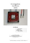
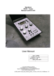
Pulse Generator
for
Power Electronics
User Manual
type:
version:
document:
date:
PMG 02
1.32_eng
1.32
01.08.2006
© Ing. Büro M.Billmann 05/2004
Lerchensteige 10 • 91448 Emskirchen
Telefon +49-(0)9104-8235-88 • Fax +49-(0)9104-8235-89
email: [email protected]
PMG-02_Bed_Anleitung_v1.32_oce_eng.doc; 01.08.2006; ©M.Billmann; 1/18
ING. BÜRO M.BILLMANN
PMG 02 – Pulse Generator for Power Electronics
5
6
7
8
16
15
21
18
19
17
4
2
1
12
3
22
9
13
20
10
11
14
fig 1: front elements
27
28
23
24
25
26
fig 2: rear elements
PMG-02_Bed_Anleitung_v1.32_oce_eng.doc; 01.08.2006; ©M.Billmann; 2/18
Description of elements
Front side elements and interfaces
1.
2.
3.
4.
5.
6.
7.
8.
9.
10.
11.
12.
13.
14.
15.
16.
17.
18.
19.
20.
21.
22.
Power ON/OFF switch
Power ON LED
Decade selector switch [0,1Hz ... 1MHz]
Frequency adjustment [linearized, 10-turns per decade]
Duty cycle preselect [0 ...99%, BCD switch]
Preselect number of pulses per pulse train [0 ... 9]
Preselect synchronous trigger pulse [0 ... 9]
Selector continuous waveform / pulse train
[rep = cwfm; single = single shot pulse train]
Start pulse train / read preselection [1sec debounced]
Reset error latch [possible only with no error condition present]
Status LED error latch [red = error = all outputs in
logically OFF state]
Encoder plus status LEDs [deadtime and puls length of last pulse
within a pulse train]
Selector error logic
[a) pos. logic; b) neg. logic; c) error input disabled]
BNC input error signal [schematic page 7/14]
Adjust logic level and supply output voltage
[Uout 5 ... 15VDC; 1Amax]
BNC output Uout [for supply of e.g. an isolated IGBT driver]
Output auxiliary power supply 5VDC; 10mAmax [e.g. for optical error
receiver supply]
Trigger signal output [5V ... 15V; into 50Ω = 2,5V ... 7,5V]
Channel A output [5V ... 15V; into 50Ω = 2,5V ... 7,5V]
Channel B output [5V ... 15V; into 50Ω = 2,5V ... 7,5V]
Status selectors output logic mode
Case legs
Rear elements and interfaces
23.
24.
25.
26.
27.
28.
Multifunction connector [for fixed test setups]
Selector internal signal generation / external signal applied
BNC input for external signal
BNC input for external pulse train start
Reserved connector, not wired [reserved for possible µP interface]
Power supply input [PMG 02 will operate floating only when a
floating power supply is used here. Minus supply is close to but
not identical with BNC minus!]
PMG-02_Bed_Anleitung_v1.32_oce_eng.doc; 01.08.2006; ©M.Billmann; 3/18
1
Contens
Seite
2
About this document
2.1
How to use this document
2.2
Used symbols and abbrevations
5
5
5
3
Description
3.1
Intended usage
3.2
Safety
3.3
Warning hints, legal stuff
5
6
6
7
4
7
Functional description
5
Start – up and operation
5.1
Supply
5.2
Power ON
5.3
Select logic status and logic level
5.4
Select frequency
5.5
Select duty cycle
5.6
Select continuous wfm or pulse train
5.7
Start a pulse train
5.8
The outputs
5.9
Error input and error latch
5.10 Encoder adjustment „deadtime“ and „last pulse“
5.11 Short circuit - II setup
5.12 External signals
5.13 Rear multifunction connector X10
9
9
9
9
10
11
11
12
13
13
14
15
15
15
6
16
Failure
7
Maintainance, Service, Accessories
7.1
Maintainance
7.2
Service
7.3
Accessories
8
Annex
8.1
Declaration of Conformity
8.2
Schematic
8.3
Part location on main PCB
16
16
16
16
17
18
A1-A14
B1-B2
PMG-02_Bed_Anleitung_v1.32_oce_eng.doc; 01.08.2006; ©M.Billmann; 4/18
2
About this document
This document describes how to
- operate
- setup and adjust
- troubleshoot
the Pulse Generator for Power Electronics PMG 02
2.1
How to use this document
Please read this manual carefully, to operate the PMG 02 correctly.
On page 2 and 3 You will find the control elements and interfaces listed in
graphical illustration to get an easy link to the description in this manual.
This document targets to the following group of persons:
- Professionals in Power Electronics
- Electronics engineers in the field of gate driver developement
2.2
Hint
Warning
Used Symbols and abbreviations
Hints describe the advantages of certain adjustments and
setups and assist You to draw out maximum performance of
the unit.
Warnings: Read and follow these instructions carefully!
Warnings shall prevent people from danger and help to avoid
damage of the unit or the device under test.
PMG-02_Bed_Anleitung_v1.32_oce_eng.doc; 01.08.2006; ©M.Billmann; 5/18
3
Description
the PMG 02 is a two channel square wave functional pulse generator with
additional trigger output.
An error input with error latch shuts down output signals on demand. A
buildt in auxiliary power supply can be used to supply external gate drive
units. A deadtime and the duration of the last pulse of a pulse train can be
adjusted by setting up an internal encoder.
3.1
Intended Usage
This unit is designed for industrial use in electronic laboratories and test
benches of power electronics, only.
This unit is able to generate single pulses, pulse trains and continuous
waveforms suitable for characterization of power semiconductors, gate
drive units and power inverters.
Use this unit in dry and suitable clean areas only.
3.2
Safety
This section is for Your safety. Please read this section carefully before
operating the PMG 02.
Qualified personal
The PMG 02 may only be started and operated by qualified personal.
Qualified is, who
- has suitable technical training
and
- has got technical instruction from a trained user or the manufacturer
concerning the start up and the operation of the PMG 02
and
- has access to this manual at any time.
Reservations of the manufacturer
Maintainance and service may only be fulfilled by qualified service personal
with suitable technical training.
Always disconnect all energy sources when electrical or mechanical
service is applied.
Spare parts as well as tools must meet the technical demands of the
manufacturer. For preservation of warranty original replacement parts must
be used only.
Technical details may change without notice.
PMG-02_Bed_Anleitung_v1.32_oce_eng.doc; 01.08.2006; ©M.Billmann; 6/18
3.3
Warning hint, exclusion of liability
This unit generates pulse patterns that are suitable to test power electronic
systems. It is always possible and – depending on the target of
investigations – to exceed the limits of devices under test.
Warning
The Pulse Generator PMG 02 is able to generate pulse
patterns that may cause malefunction, degradation or damage
of (high energy) systems which may lead to consequential
damage of persons and / or asset values.
Suitable personal security action must strictly be used!
Always use isolated gate drive units when characterizing
semiconductors or inverter systems operating at dangerous
voltages.
Any liability for damages caused by the use of this Pulse Generator PMG
02 is excluded!
4
Functional description
The PMG 02 is designed as a two channel pulse generator for digital
square wave output impulses with additional trigger output.
It´s logic level is adjustable [15] up to 15V and invertable for both channels.
Both channels may be disabled, also. This configuration will preset into
which logic level the outputs will move in case of a set error latch.
A buildt in auxiliary power supply [16] from 5V to 15V (1A max.) is provided
to supply (external, isolated gate) driving units.
An adjustable, linearized [4] frequency range from 0.1 Hz to 1 MHz is
covered over 7 decades [3] and a presettable duty cycle [5] from 0% to
99% (1% steps, at 1 MHz decade 5% to 95% in 1 % steps at the 50 Ω
outputs) provides jitter free output signals in the first instance.
An error input [14] is configurable for either positive or negative logic [13].
The buildt in error latch will disable all output signals immediately. A set
error latch will force all outputs into logically OFF, depending on the
position of the status switches [21]
The error latch is reset by the „reset“ buttom [10]. This will only be
successful if no more error is present.
The outputs [19; 20] tolerate and are matched to a 50Ω load. They also are
suitable to directly drive LEDs or fibre optical transmitters.
PMG-02_Bed_Anleitung_v1.32_oce_eng.doc; 01.08.2006; ©M.Billmann; 7/18
The operator may choose [8] between continuous waveform and pulse
trains on demand by pushing the „start“ buttom [9].
Pulse trains from 1 to 9 pulses length [6] are presettable, with a one second
debounced „start“ buttom triggered repetition rate.
From two or more pulses on the last pulse has a maximum length of about
15µsec as long as the encoder is in „default“ mode. This is used for pulse
reduction in terms of overload protection when measurements close to
nominal semiconductor current are performed.
At the trigger output [18] a trigger pulse is presettable [7] synchronous to
one of the up to nine pulses that are generated.
This trigger pulse is synchronous to the output pulses even in case of an
earlier shutdown due to a set error latch.
Hint
If e.g. 2 pulses are presetted and trigger is set to the 4th pulse
no trigger pulse will be generated.
A valid trigger signal will only be present as long as n(trigger)
[7] ≤ n(puls) [6].
An external (one channel) digital signal [25] can be handed forward to the
outputs. Hereby functions as level shifter, deadtime generator,
jittergenerator output amplifier, error latch and logic conversion are
considered. This signal may be splitted into 2 complementary output
signals.
External signals are clocked in with a variable maximum jitter time.
Maximum jitter is adjustable [4] from 20nsec up to much more than
100µsec [3].
Pushing and turning the encoder knob [12] a variable deadtime in coarse
and fine steps is adjusted from 20nsec to very long values. In the encoder
menue „last pulse“ the length of the last pulse of a pulse train is varied.
Hint
A negative deadtime (overlapping pulses) is possible to
appreciate shoot through or optimization tasks in a halfbridge,
or at resonant DC/DC converter topologies. It is also desirable
for pulse overlap in current fed inverters or matrix inverters.
Hinweis
Deadtimes (overlap times) up to about 160µsec may also be
used for short circuit – II setups.
PMG-02_Bed_Anleitung_v1.32_oce_eng.doc; 01.08.2006; ©M.Billmann; 8/18
5
Start up and operating the unit
5.1
Supply
As supply [28] any voltage in the range of 18V-28VDC may be used. The
internal power consumption is < 0.3A, but the power supply must be able to
cover additional connected loads.
Hint
5.2
The supply ground is not identical but close to the BNC output
ground.
Power ON
Turning the unit into ON state is created by toggling the „power ON“ [1]
switch.
The PMG 02 will signal this with a green illuminated „ON“ LED [2], a yellow
illuminated „default“ LED and with the error latch status LED [11] in red
colour.
Hint
5.3
Whatever was set up during last operation will be ignored
when powering up the PMG 02 again. The unit will always
restart with a set error latch, deadtime = OFF and last pulse =
„default“ (about 15µsec).
To receive output pulses the error latch must be reset by
pressing the „reset“ buttom [10] or by operating the reset pin
at the rear side multifunction connector [23]. After a re-power
up sequence the „start“ buttom additionally must be pressed
to take over the actual preset values.
Select logic mode and logic level
At first please start to select the definition for the output logic.
1.)
Hint
Select the output voltage level Uout [15]. Control the output voltage
e.g. with a voltmeter at BNC output [16]
- Uout turn to left stop <5V
- Uout turn to right stop > 15V
Logic levels from 2.5V to 7.5V can be accieved by insertion of
a 50Ω feed through adapter which will divide the output
voltage level by two. Attention: Take maximum power rating of
these feed through units into consideration!
PMG-02_Bed_Anleitung_v1.32_oce_eng.doc; 01.08.2006; ©M.Billmann; 9/18
2.)
Selection of logic modes with „mode“ switches CH_A, CH_B [21].
Please choose from the diagram below.
switch position
operating Pulse form
mode_A
mode_B
CH_A
CH_B
upper
lower
"
"
0V
0V
upper
middle
"
0V
0V
0V
upper
upper
"
"
0V
0V
lower
lower
"
"
Uout
Uout
lower
middle
"
Uout
Uout
Uout
lower
upper
"
"
Uout
Uout
middle
lower
Uout
"
Uout
0V
middle
middle
0V
0V
0V
0V
middle
upper
0V
"
0V
Uout
CH_B
These switches are mechanically latched to prevent an accidental, unwanted switch over. To change the switch position
please first pull out the toggle and then change the position.
The PMG 02 is optional availiable with „non latching“
toggle switches.
Opposite output signals are received in A-positive logic by
setting mode_CH_A into upper and mode_CH_B into lower
position.
Hint
5.4
CH_A
level in error mode
Frequency selection
The frequency may be varied within 7 decades [3] and a 10-turn knob [4].
1.)
2.)
3.)
Decade selection
0,1Hz-1Hz-10Hz-100Hz-1kHz-10kHz-100kHz-1MHz
Tuning within a decade is linearized. This means that 0-100%
potentiometer display corresponds to 0-100% output frequency of this
decade.
The internal frequenqy generator will lead to output signals only if the
rear side „intern-extern selector“ is in positon „intern“.
Hinweis
Although such generated frequencies are handed through an
internal digital system the output frequency is jitter free as
long as no deadtime is choosen. Variing the frequency is
possible during operation at any time e.g. to fine tune pulse
length or sweep a desired range.
PMG-02_Bed_Anleitung_v1.32_oce_eng.doc; 01.08.2006; ©M.Billmann; 10/18
5.5
Selection of duty cycle
Preset the desired duty cycle by the 2 digit digital switch array
„duty [%]“ [5].
1.)
2.)
Hint
Choose between 0% and 99% in 1%-steps
A changed duty cycle will be taken over by pressing the
„start“ knob [9]
The output pulses are free from jitter and do not depend on a
chooosen duty cycle.
At duty = 0% neither output pulses nor trigger pulses are
generated.
Minimum and maximum duty cycles will not be reproduced
correctly in the highest decade at the 50Ω outputs. If e.g. 1%
duty at 1MHz is required please take these pulses from the
multifunction connector [23] in fixed 5V HCMOS level.
Example for application:
Performing a single pulse short circuit test with a given DC link
voltage and a fixed (inductive) load a very comfortable working of
this process can be accieved by usage of the duty cycle array.
The target value of the maximum (switched off) current can
additionally be fine tuned by the 10-turn potentiometer [4].
5.6
Repetetive mode or pulse train
The position of the „rep / single“ switch [8] decides wether permanent
oszillation (continuous waveform) or a single pulse sequence is produced
at the outputs.
Hint
This switch is mechanically latched and therefore protected
against accidental switching over. Please pull out the toggle
before performing a change in switch position.
PMG-02_Bed_Anleitung_v1.32_oce_eng.doc; 01.08.2006; ©M.Billmann; 11/18
Examples for application:
Continuous waveform :
- Testing gate driver circuits in terms of power dissipation, current
consumption, general functionality.
Single pulse:
- Short circuit - I test, e.g. preset 10µsec pulse length, feed back a
suitable generated error message into the generator´s error input
to guarantee a pulse width reduction to prevent a system
overload.
- Evaluation of switch OFF losses
Double pulse :
- Commutation,
- Reverse recovery behaviour of diodes,
- Switch ON losses
Multi pulse :
- start up a resonant system and evaluate
a steady resonant condition
5.7
Start pulse trains (pulse sequences)
In „single“ mode a preset [6] pulse train begins by pushing the „start“
knob [9]. For more than 1 pulse (n>1) the last pulse will have a maximum
length of 15µsec while the encoder is in default position. A trigger pulse
can be choosen [7] synchronous to any of the n pulses.
A change in duty cycle [5] will be recognized with the next time the „start“
knob [9] is pushed. The „start“ knob is debounced by 1 sec to provide
sufficient time for cooling down a device under test. Another possible start
option is given by shortening the rear side „start_in“ BNC connector [26] or
by usage of the corresponding signal at the multifunction connector X10
[23].
By cascading two or more of the PMG 02 much more complex pulse
patterns (e.g. phase shift,...) are possible.
Hint
The rear side „start_in“ inputs are less debounced and allow a
faster repetition (>100Hz). Trained service personal may
chance this debouncing time by a hardware change, please
see schematic page 8/14.
PMG-02_Bed_Anleitung_v1.32_oce_eng.doc; 01.08.2006; ©M.Billmann; 12/18
5.8
The outputs
The BNC outputs „CH_A“, „CH_B“ and „Trigger_out“ are designed to drive
50Ω loads. Also they are able to drive optical transmitters for fibre optical
pulse transfer. Parallel to the front side BNCs they are availiable at the rear
multifunction connector X10 [23].
Rise and fall times are better than 10nsec.
Hint
5.9
The outputs are current limited and clamped to the internal
supply for protection against external overvoltages. In case of
short circuit for several minutes the output drivers may suffer
from thermal overload.
Error input and error latch
The PMG 02 has an logically selectable error input [13] followed by an error
latch. The toggle switch has 3 possible positions:
a) pos. logic
b) negative logic
c) error input disabled
(right position; LOW = no error)
(left position; HIGH = no error)
(center position; error input ignored)
Setting the error latch stopps all output signals immediately. If error is set
during a trigger pulse the trigger signal will also be cut off.
Reset of the error latch is possible by pushing the „reset“ knob [10] and will
be successful only if no error is present.
If a fibre optical receiver is choosen for feedback of an error signal an
auxiliary power tab [17] provides up to 5VDC; 10mAmax to supply the optical
receiver.
Hint
The PMG 02 has an internal power good monitor for various
internal supply voltages. This information is linked to the error
latch and sets the unit into error state while powering up.
PMG-02_Bed_Anleitung_v1.32_oce_eng.doc; 01.08.2006; ©M.Billmann; 13/18
5.10
Encoder setup „deadtime and „last pulse“
The PMG 02 has an encoder menue for presetting deadtime and last pulse functions.
It is operated by pushing and turning the encoder [12].
menue
options
power on
1st
push
2nd
push
3rd
push
4th
push
5th
push
6th
push
Hint
default
yellow
yellow,
off,
red
yellow,
off,
red
yellow, off,
red
yellow
off,
red
yellow, off,
red
yellow
status LEDs
deadtime
last pulse
-
remark
freeze
-
red
-
-
yellow
-
-
-
red
-
-
orange
(≠ default)
-
yellow,
red (= long)
-
yellow
-
-
-
PMG 02 is in default mode; means no deadtime,
last pulse length about 15µsec
coarse adjust deadtime (up to about 160µsec)
deadtime > 0; default LED turns off
deadtime < 0; default LED red as additional warning
fine adjust deadtime (in 20nsec steps)
deadtime > 0; default LED turns off
deadtime < 0; default LED red as additional warning
„last pulse“ is as long as previous pulses, means
= „long“; (default LED is red at negative deadtimes)
Pulse length adjustment of last pulse; maximum
length is about 80µsec, but max as long as previous
pulses. At extremely long previous pulses length will
jump from 80µsec directly to max pulse length of
previous pulses, LED will turn red then.
Al setup adjustments are freezed, accidentially turning
the encoder will not change the setup.
Jump back into „default mode“; made adjustments
keep stored until power is turned off.
Powering down the PMG 02 will erase all adjustments made in the encoder menue.
The PMG 02 will restart in „default mode“.
PMG-02_Bed_Anleitung_v1.32_oce_eng.doc; 01.08.2006; ©M.Billmann; 14/18
If deadtime = 0 is set by encoder deadtime will jitter ± 20nsec
around zero deadtime. No jitter is availiable in „default mode“
only.
„last pulse = default = about. 15µsec“ signalized with a yellow
illuminated „last pulse“ LED
Hint
5.11
Short circuit - II setup
The outputs „CH_A“, „CH_B“ of the PMG 02 do not neccessarily have to
serve a half bridge topology. A encoder setup can be found that one channel
can ramp a standard load current (at inductive load) into a device under test.
After a ramping time of e.g. several 10µsec a larger short circuit-II switch
may short the load and a power electronic system may also be
characterized in this condition.
Warning
5.12
It is strongly recommended to implement the PMG 02´s error
input while performing such kind of evaluations!
External signals
An external, one phase digital signal [25] may be handed thru the outputs.
Features like level shifter, deadtime generator, jitter generator, output
amplifier, split into complementary signals, error shutdown mode, can be
used hereby. External signals can be clocked in with a variable jitter. This
jitter is adjustable [10] from 10nsec up to 10sec(!) [3]. This is realized by
using the internal frequency generator block to clock in the external
information. Minimum jitter is accieved in the highest (1MHz) decade
and maximum right position of the frequency adjustment knob [4].
Jitter free handling of external signals on request. Propagation delay times
are kept short and additionally depend on the logic level used. Signal
interfaces can be looked up on page 8/14 of the schematic.
5.13
Rear multifunction connector X10
If only one PMG 02 is availiable in a lab the user has the possibility for
various fixed test setups by use of the rear multifunction connector X10 [23].
All major signals are present at X10. A fixed test bench e.g. Switch OFF
losses or reverse recovery losses can be wired to this connector.
Additionally the outputs A, B, Trigger are availiable at 5V HCMOS level.
They will provide maximum and minimum duty cycles even in the highest
decade.
For smaller auxiliary circuits supply voltages as 3.3V, 5V and Uout are
present there.
Please consider schematic, page 2/14 „rear remote connector“ for further
details.
PMG-02_Bed_Anleitung_v1.32_oce_eng.doc; 01.08.2006; ©M.Billmann; 15/18
6
Failure
In case of failure immediately disconnect and power down the PMG 02. In
case of damages please consult us directly.
7
Maintainance, Service, Accessories
7.1
Maintainance
This unit does not need maintainance. It may only be operated in dry, clean
areas.
Take care that the unit is kept in a non dusty condition. Dust may cause
dysfunction or reduced performance.
Abandonment
1. Turn the unit OFF
2. Disable all energy sources and disconnect from mains and supply.
Disassembly
For disassembly proceed as followes:
1. Dismount the unit into single components.
2. Sort these components for material plus disposal criteria and hand it to
an official waste management.
Disposal
Hint
7.2
Respect the specific disposal regulations of Your country.
Service
Never carry out repair on Your own, please contact:
Ing.-Büro M.Billmann
Lerchensteige 10
D-91448 Emskirchen
phone:
fax:
email:
+49-(0)9104-8235-88
+49-(0)9104-8235-89
[email protected]
PMG-02_Bed_Anleitung_v1.32_oce_eng.doc; 01.08.2006; ©M.Billmann; 16/18
7.3
Accessoires
The PMG 02 was developed considering a long year experience in power
electronics. The wish for „useful things to make power electronics design
and application engineers life easier“ was main issue.
In correlation to accieve this goal tere is availiable a variety of
- fibre optical transmitters
- fibre optical receivers (error input, scope trigger, ...)
- adaptors for Semikron SKiiP® interfaces
For custom specific demands or special options please contact us directly.
Quantity and function of accessoiry parts availiable on stock is in permanent
growth.
Computer aided remote control [27] on request.
8
Annex
This section provides additional documentation that were given by
Ing.-Büro M.Billmann or third parties:
8.1
Declaration of Conformity
8.2
Schematic of PMG 02
8.3
Part location on main PCB
8.4
Patch 01
PMG-02_Bed_Anleitung_v1.32_oce_eng.doc; 19.05.2004; ©M.Billmann; 17/18
Dipl. Ing. Markus Billmann
Lerchensteige 10
91448 Emskirchen
Dipl. Ing. M. Billmann · Lerchensteige 10 · 91448 Emskirchen
Declaration of Conformity
Manufacturers name and adress
Ing.-Büro Markus Billmann
Lerchensteige 10
91448 Emskirchen
The Ing. Büro M.Billmann herewith declares conformity of the product
Product name
Pulse Generator for Power Electronic Measurements
Type:
PMG 02
Options:
-
With applicable regulations
EMV Directive 89/336/EWG amended by 91/263/EWG, 92/31/EWG
Low-Voltage Equipment Directive 73/23/EWG amended by 93/68/EWG
Harmonized standards applied
Safety
EN61010-1 (VDE 411-1)
Safety instructions for electronic laboratory devices
EN60664 (VDE 0110)
Isolation
Pollution degree: 1
Technical documentation is fully provided.
Operators manual is attached.
Emskirchen, den 19.05.04
M.Billmann (C E O)
PMG-02_Bed_Anleitung_v1.32_oce_eng.doc; 19.05.2004; ©M.Billmann; 18/18