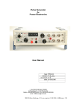
1
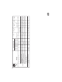
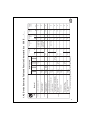
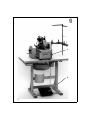
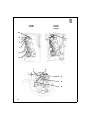
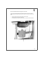
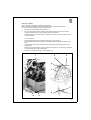
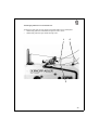
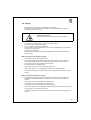
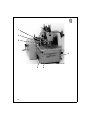
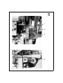
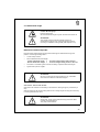
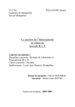
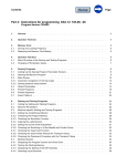
Contents
Page:
Home
Preface and General Safety Notes
Part 1: Operating Instructions Cl. 558
1.
1.1
1.2
1.3
1.4
1.4.1
1.4.2
1.5
Product Description .
Short Description . . .
Sub-classes . . . . . .
Technical Specification
Sewing Devices . . . .
Device Summary Table
Device Summary Table
Optional Equipment .
2.
2.1
2.2
2.3
2.4
2.5
2.6
2.7
2.8
2.9
2.10
2.11
2.12
2.13
2.14
2.15
2.16
2.17
2.18
2.19
Operation . . . . . . . . . . . . . . . . . . . . .
Removal and Placement of the Clamp Plates .
Turning On - Quick Stop - Restart . . . . . . . .
End Position of the Sewing Machine . . . . . .
Needles, Threads and Gimps . . . . . . . . . .
Threading of the Underthread (Hook Thread) .
Threading the Gimps . . . . . . . . . . . . . . .
Threading of the Upper Thread (Needle Thread)
Thread Tension . . . . . . . . . . . . . . . . . .
Sewing . . . . . . . . . . . . . . . . . . . . . . .
Blocking the Clamp Lift . . . . . . . . . . . . . .
Buttonhole Length . . . . . . . . . . . . . . . .
Cutting Length . . . . . . . . . . . . . . . . . .
Cutting Blocks . . . . . . . . . . . . . . . . . . .
Cutting Pressure . . . . . . . . . . . . . . . . .
Spreading of the Material . . . . . . . . . . . .
Stitch Density . . . . . . . . . . . . . . . . . . .
Seam Width . . . . . . . . . . . . . . . . . . . .
Buttonhole Form . . . . . . . . . . . . . . . . .
Changeover to Cutting Before or After Sewing
.
.
.
.
.
.
.
.
.
.
.
.
.
.
.
.
.
.
.
.
.
.
.
.
.
.
.
.
.
.
.
.
.
.
.
.
.
.
.
.
3.
3.1
3.2
3.3
Maintenance .
Cleaning . . . .
Lubrication . .
Oiling Positions
.
.
.
.
.
.
.
.
.
.
.
.
.
.
.
.
.
.
.
.
.
.
.
.
. . . . . . . . . . . . . . . . .
. . . . . . . . . . . . . . . . .
. . . . . . . . . . . . . . . . .
. . . . . . . . . . . . . . . . .
. . . . . . . . . . . . . . . . .
and Function Characteristics
and Function Characteristics
. . . . . . . . . . . . . . . . .
.
.
.
.
.
.
.
.
.
.
.
.
.
.
.
.
.
.
.
.
.
.
.
.
.
.
.
.
.
.
.
.
.
.
.
.
.
.
.
.
.
.
.
.
.
.
.
.
.
.
.
.
.
.
.
.
. . .
. . .
. . .
. . .
. . .
578
558
. . .
. . . . .
. . . . .
. . . . .
. . . . .
. . . . .
E... /...
E ... / ...
. . . . .
.
.
.
.
.
.
.
.
.
.
.
.
.
.
.
.
.
.
.
.
.
.
.
.
5
5
6
7
8
9
11
13
.
.
.
.
.
.
.
.
.
.
.
.
.
.
.
.
.
.
.
.
.
.
.
.
.
.
.
.
.
.
.
.
.
.
.
.
.
.
.
.
.
.
.
.
.
.
.
.
.
.
.
.
.
.
.
.
.
.
.
.
.
.
.
.
.
.
.
.
.
.
.
.
.
.
.
.
.
.
.
.
.
.
.
.
.
.
.
.
.
.
.
.
.
.
.
.
.
.
.
.
.
.
.
.
.
.
.
.
.
.
.
.
.
.
.
.
.
.
.
.
.
.
.
.
.
.
.
.
.
.
.
.
.
.
.
.
.
.
.
.
.
.
.
.
.
.
.
.
.
.
.
.
.
.
.
.
.
.
.
.
.
.
.
.
.
.
.
.
.
.
.
.
.
.
.
.
.
.
.
.
.
.
.
.
.
.
.
.
.
.
.
.
.
.
.
.
.
.
.
.
.
.
.
.
.
.
.
.
.
.
.
.
.
.
.
.
.
.
.
.
.
.
.
.
.
.
.
.
.
.
.
.
.
.
.
.
.
.
.
.
15
15
19
23
24
27
31
37
41
45
47
49
53
57
58
59
61
63
65
67
.
.
.
.
.
.
.
.
.
.
.
.
.
.
.
.
.
.
.
.
.
.
.
.
.
.
.
.
.
.
.
.
.
.
.
.
.
.
.
.
.
.
.
.
.
.
.
.
70
70
71
72
. . . . . . . . . . . . . . . . . . . . . . . . . . .
4.
Malfunction Remedies
5.
5.1
5.2
5.3
5.4
5.5
5.5.1
5.5.2
5.5.3
5.5.4
5.5.5
5.6
5.6.1
5.6.2
5.6.3
5.6.4
5.6.5
5.6.5
Optional Equipment Electromagnetic Upper Thread Catcher
General . . . . . . . . . . . . . . . . . . . . . . . . . . . . . . .
Electrical Connection . . . . . . . . . . . . . . . . . . . . . . . .
Function Sequence . . . . . . . . . . . . . . . . . . . . . . . . .
Turn-on Interlocks . . . . . . . . . . . . . . . . . . . . . . . . . .
Setting . . . . . . . . . . . . . . . . . . . . . . . . . . . . . . . .
Lift of the Electromagnet . . . . . . . . . . . . . . . . . . . . . .
Base Position of the Upper Thread Catcher . . . . . . . . . . . .
Lowering Movement . . . . . . . . . . . . . . . . . . . . . . . . .
Gripping Movement . . . . . . . . . . . . . . . . . . . . . . . . .
Switches for the Upper Thread Catcher Controls . . . . . . . . .
Attachment . . . . . . . . . . . . . . . . . . . . . . . . . . . . .
Pre-assembling the Wiring Distributor . . . . . . . . . . . . . . .
Laying the Wiring . . . . . . . . . . . . . . . . . . . . . . . . . .
Control Unit . . . . . . . . . . . . . . . . . . . . . . . . . . . . .
Mounting Switch b3 . . . . . . . . . . . . . . . . . . . . . . . . .
Mounting the Switching Rail for Switch b2 . . . . . . . . . . . .
Mounting the Upper Thread Catcher on the Machine Arm . . . .
.
.
.
.
.
.
.
.
.
.
.
.
.
.
.
.
.
.
.
.
.
.
.
.
.
.
.
.
.
.
.
.
.
.
.
.
.
.
.
.
.
.
.
.
.
.
.
.
.
.
.
.
.
.
.
.
.
.
.
.
.
.
.
.
.
.
.
.
.
.
.
.
.
.
.
.
.
.
.
.
.
.
.
.
.
.
.
.
.
.
The illustrations used in these instructions are of differing sub-classes of the
buttonhole machine 558 !
Please note that your buttonhole may deviate from the illustrations !
76
79
79
81
81
85
87
87
87
89
91
92
97
97
99
101
102
103
104
1. Product Description
1.1 Short Description and Proper Use
The DÜRKOPP ADLER 558 is a double chain stitch buttonhole machine.
Buttonholes with or without eye and with or without taper bar can be sewn.
•
•
•
•
•
•
•
•
The buttonhole form is determined by 2 exchangeable disc cams with
corresponding knives. The upper disc cam determines the form of the eye. The disc
cam lying thereunder determines for buttonholes with taper bar the taper bar form
and the buttonhole length.
The smallest and largest buttonhole width for each sewing device (E no.) is
established by the position of the limit plate.
Pendulum swing of the needle bar from the rest position one-sided to the right
when sewing the right and one-sided to the left when sewing the left buttonhole
seam.
Automatic adaption of the upper cloth clamp pressure to differing material
thicknesses through spring-hangered clamp frame.
The safety devices do not have to be removed when tilting up the machine.
The combined finger-eye protection device increases safety.
It is held in the work position by springs.
The gas pressure spring aids tilting up and effects a sure, slow lowering. The stop
position makes an unhindered threading of the hook thread possible.
The machine is equipped with a central oil wick lubrication from 2 oil reservoirs
(the positions marked in red must also be oiled).
In the next chapter the individual sub-classes are described.
5
1.2 Sub-classes
558 - 211241
With automatic trimmers.
The upper thread, the underthread and the gimp fed in from the bottom are cut so short
that no thread ends are visible. Cleaning is unnecessary.
Cutting open the buttonhole after sewing.
Cutting length 20 mm
558 - 221301
With automatic trimmers.
The upper thread is cut off short. The underthread and the gimp fed in from the bottom
are cut off long (about 30 mm).
Cutting open the buttonhole depending on E no. before or after sewing, as desired.
This sub-class has the electromagnetic upper thread catcher as standard equipment.
Cutting length 10...38 mm
558 - 231391
With automatic trimmer.
Only the upper thread is cut short. The sewing piece can be easily removed from the
sewing position or, with buttonholes lying in a row, simply pulled a bit to the left. The
underthread and the lower gimp are then trimmed by hand.
With this sub-class the sewing piece is positioned 12 mm further forward than with
-221301 and -251301.
Cutting open of the buttonhole, depending on the E no., as desired, before or after
sewing.
Cutting length 10...38 mm
558 - 241291
The sewing piece is positioned 9.5 mm further forward than with sub-classes -221301
and - 251301. This means a better view and more freedom when positioning the sewing
pieces.
With automatic trimmers.
The upper thread, the underthread and the gimp fed in from the bottom are trimmed so
short that no thread ends are visible. No cleaning is necessary.
Cutting open the buttonhole after sewing.
Cutting length dependent on the length package 14...32 mm
558 - 251301
With automatic trimmer.
Only the upper thread is cut short. The sewing piece can be easily removed from the
sewing position or, with the buttonholes lying in a row, simply pulled a bit to the left. The
underthread and the lower gimp are then trimmed by hand.
Cutting open the buttonhole can be switched between cutting before or after sewing.
Cutting length 10...50 mm
6
1.3 Technical Specification
Number of stitches:
Type of stitch:
Sewing length:
Cutting length:
Needle system:
Needle thickness:
Looping stroke:
Material thicknesses:
Sewing thread thickness:
Nominal voltage:
Noise:
Dimensions:
Weight:
Work height:
1.650 Stitches/min
Double chain stitch
max. 50 mm
max. 50 mm
558
Nm 90...110
Depending on the type of sewing thread and the material.
2.7...3.2 mm
Depending on the sewing device (E no.).
max. 10 mm with sub-class -221301
max. 12 mm with all othersub-classes
Upper thread max. Nm 50
Underthread max. Nm 30
- 2410591
3 ~ 400 V + N, 50/60 Hz
- 2410575
3 ~ 230 V, 50/60 Hz
- 2410540
1 ~ 230 V, 50 Hz
- 2410478
1 ~ 230 V, 60 Hz
The machine is delivered with one of the listed drive
packages appropriate to the nominal voltage.
Lc = 80 dB (A)
by sewing cycle 5.0 s on and 1.4 s off
to DIN 45635-48-B-1
(H x W x D)
1570 x 630 x 520 mm (Standard)
1570 x 1060 x 520 mm (Wide model)
128 kg
(complete with machine head,
frame and motor)
55 kg
(only frame and motor)
760...1060 mm
(Top edge of table)
7
1.4 Sewing Devices
The devices parts for the different buttonhole forms and cutting lengths are established
under device numbers (E no.’s).
After the E no. behind a slash the cutting length or the setting range in mm is given.
578 E2107 / 20
or
578 E209 / 10 - 38
Example:
558 E209 / 10 - 38
For sewing the various buttonhole lengths different cutting blocks, cloth clamps and disc
cams are required. The appropriate order numbers can be found in the device sheet for
the 558.
The device summary table on the following page lists the currently available devices.
The most suitable device for a specific buttonhole form and a certain type of material
can be chosen quickly from the table.
ATTENTION :
For the 558 after July 1994 the device numbers for the 578 apply ( Chapter 1.4.1 ).
For the 558 up to June 1994 the device numbers for the 558 apply ( Chapter 1.4.2 ).
There are two different groups of buttonhole machines:
Only cutting after sewing.
Cutting before or after sewing as desired.
For conversion of the buttonhole machine to a further buttonhole form or cutting length
the following points are to be considered:
1. Only those parts are to be ordered and attached whose order numbers do not agree
with those of the device available.
See the device sheets for the 558 and the 578.
2. The cutting lengths can only be selected appropriate to the device or the setting
range.
By devices which have only one digit behind the slash the cutting length is not
adjustable.
3. By machines which are switched over to cutting before or after sewing, the
appropriate sections of these instructions are to be observed.
4. The setting values, buttonhole width and looping stroke, are interdependent and must
be observed when changing to another device (E no.).
If values deviating from the table arise, the adaption is to be made by a specialist as
per the Service Instructions.
8
9
- 231391
- 221301
- 211241
558
E309 /
18 + 24
Buttonholes similar to handworked
quality in outerwear
E213 /
10 - 38
E328 /
16 - 20
E312 /
12 - 34
E2107 /
20
E311 / *
6 - 34
* The construction set upper gimp guide 578 5101 must be ordered additionally .
Fine, tightly woven materials
(e.g. poplin)
E334 /
10 - 38
E327 /
10 - 38
Garment leather
Waistbands on jeans,
graduated cloth clamps
E312 /
10 - 38
Materials of variing quality and
thickness
Small buttonholes in elastic material
(e.g. knitware) with round or flat gimp
Loose, coarse weave cloth
E212 /
10 - 38
E209 /
10 - 38
High quality clothing of
variing thicknesses
Buttonholes similar to
handworked quality
Loose, coarse weave cloth
Material
Buttonhole form
V <---
V <---
V <---
V <--
before
---> N
---> N
---> N
---> N
---> N
---> N
---> N
---> N
after
Cutting
"
"
"
"
"
Upper thread
"
Upper thread,
Under thread,
Gimp long
Upper thread,
Under th., Gimp
6,0
4,5
5,0
5,0
4,1
4,1
5,0
4,1
4,5
min.
mm
7,0
5,8
7,0
7,0
5,2
5,2
7,0
5,2
5,8
max.
mm
Buttonhole
width
-
0,4
- / 0,6
- / 0,4
0,4
0,4
- / 0,4
0,4
0,4
mm
Cutting
area
578 E . . . / . . .
Short trimmer
for
1.4.1 Device Summary Table and Function Characteristics
2,7
3,0
3,2
2,7
3,2
3,0
2,7
3,0
2,7
mm
Looping
stroke
10
- 251301
- 241291
558
E512 /
10 - 50
E512 /
12 - 50
E2431 /
L1 - L4
Loose, coarse weave cloth,
plastic stitch formation
Materials of variing quality and
thickness
E2417 /
L1 - L3
E2407 /
L1 - L3
Waistbands on jeans and similar
Buttonholes in elastic material
(e.g. knitware)
Loose, coarse weave cloth
Nähgut
Buttonhole form
V <---
before
---> N
---> N
---> N
---> N
after
Cutting
Upper thread
"
"
Upper thread,
Under th., Gimp
Short trimmer
for
5,0
4,5
4,5
4,5
min.
mm
7,0
5,8
5,8
5,8
max.
mm
Buttonhole
width
/ 0,4
0,4
0,4
0,4
mm
Cutting
area
2,7
2,7
3,0
2,7
mm
Looping
stroke
11
- 31391
- 21301
- 11241
558
E213 /
10 - 38
E328 /
16 - 20
E312 /
12 - 34
E107 /
20
E311 / *
6 - 34
* The construction set upper gimp guide 578 5101 must be ordered additionally .
Fine, tightly woven materials
(e.g. poplin)
E334 /
10 - 38
E327 /
10 - 38
Garment leather
Waistbands on jeans,
graduated cloth clamps
E312 /
10 - 38
E309 /
18 + 24
E212 /
10 - 38
E209 /
10 - 38
Materials of variing quality and
thickness
Small buttonholes in elastic material
(e.g. knitware) with round or flat gimp
Buttonholes similar to handworked
quality in outerwear
Loose, coarse weave cloth
High quality clothing of
variing thicknesses
Buttonholes similar to
handworked quality
Loose, coarse weave cloth
Material
Buttonhole form
V <---
V <---
V <---
V <--
before
---> N
---> N
---> N
---> N
---> N
---> N
---> N
---> N
after
Cutting
"
"
"
"
"
Upper thread
"
Upper thread,
Under thread,
Gimp long
Upper thread,
Under th., Gimp
6,0
4,5
5,0
5,0
4,1
4,1
5,0
4,1
4,5
min.
mm
7,0
5,8
7,0
7,0
5,2
5,2
7,0
5,2
5,8
max.
mm
Buttonhole
width
-
0,4
- / 0,6
- / 0,4
0,4
0,4
- / 0,4
0,4
0,4
mm
Cutting
area
558 E . . . / . . .
Short trimmer
for
1.4.2 Device Summary Table and Function Characteristics
2,7
3,0
3,2
2,7
3,2
3,0
2,7
3,0
2,7
mm
Looping
stroke
12
- 51301
- 41291
558
E512 /
10 - 50
E512 /
12 - 50
E431 /
L1 - L4
Loose, coarse weave cloth,
plastic stitch formation
Materials of variing quality and
thickness
E417 /
L1 - L3
E407 /
L1 - L3
Waistbands on jeans and similar
Buttonholes in elastic material
(e.g. knitware)
Loose, coarse weave cloth
Nähgut
Buttonhole form
V <---
before
---> N
---> N
---> N
---> N
after
Cutting
Upper thread
"
"
Upper thread,
Under th., Gimp
Short trimmer
for
5,0
4,5
4,5
4,5
min.
mm
7,0
5,8
5,8
5,8
max.
mm
Buttonhole
width
/ 0,4
0,4
0,4
0,4
mm
Cutting
area
2,7
2,7
3,0
2,7
mm
Looping
stroke
1.5 Optional Equipment
558 - 10012 Electromagnetically operated upper thread catcher
The electromagnetically operated upper thread catcher immediately after the thread
trimming procedure grips the upper thread. It holds this clamped and inserts it in the
right seam during sewing of the next buttonhole.
This means:
•
•
•
Secure seam beginning even with light, loose cloth.
Beginning stitches pulled tight.
Neating the underside of the buttonhole is unnecessary because the beginning
thread is sewn over.
The sub-class 558 - 221301 has the upper thread catcher as standard equipment. It is
available on request for all other sub-classes.
558 1501
Thread oiler
For improving thread glide in extremely thickness material.
557 1103
Gimps roller holder on the table top
For lower Gimps which are stiff and hard to bend.
558 3001
Thread unreeler, complete
For holding thread or wool cones. The attachment is to the middle traverse of the table
frame.
558 1731
Stop for buttonhole interval from 70 - 330 mm
App. 1062
App. 1541
798 500088
Halogen sewing light
Mounting kit
Sewing light transformer
Stops for the clearance between material edge and buttonhole are available in different
lengths on request.
13
1
4
2
2
3
5
6
7
7
2
2
8
8
9
9
10
10
14
2. Operation
2.1 Removal and Placement of the Clamp Plates
Caution Risk of Injury !
Pull the mains plug.
Remove or place the clamp plates only with the machine
turned off.
The removal or placement of the clamp plates 3 and 5 occurs in the machine end
position (see Chapter 2.3).
The clamp operating lever 1 must be open !
This is the case when it is pushed to the back until it hits.
ATTENTION !
In order to avoid damage to the needle the combined
finger-eye protection 4 must remain swung down.
Sub-class -231391 and -251301:
Removing the clamp plates
–
–
–
Swing the clamp plate holder 2 away to the side.
Reach under each nail slit 6 and lift the clamp plate.
Remove the clamp plates to the front.
Placing the clamp plates
–
–
–
–
–
The clamp operators 8 must reach into the forks of the clamp arms.
Push the clamp plates to the right or left against the pressure screws 7 and plate
edges 9.
Place the clamp plates over the setbolt 10 on the material support plate.
Swing the clamp plates holder 2 back over the clamp plates.
The clamp plates are secured against lifting.
Check by closing the clamp operating lever 1 if the clamps open and close correctly.
15
-221301
1
1
2
3
-211241 und -241291
1
1
2
3
16
Sub-classes -211241, -221301 and -241291:
Removing the clamp plates
–
–
–
Swing the clamp plate holder 1 away to the side.
Pull the spring mounted slide 3 in the direction of the arrow and remove the right
clamp plate.
Reach under the nail slit 2 and remove the left clamp plate.
Placing the clamp plates
–
–
–
Place first the left, then the right clamp plate.
The clamp operators 5 must reach into the forks of the clamp arms.
Push the clamp plates to the right or left against the pressure screws 4 and plate
edges 6.
–
Place the clamp plates over the setbolt 7 on the the material support plate.
Hereby pull the spring mounted slide 3 in the direction of the arrow and let catch in
groove 8.
–
Swing the clamp plate holder 1 over the clamp plates again.
The clamp plates are secured against lifting.
–
Check by closing the clamp operating lever if the clamps open and close correctly.
4
4
1
1
5
5
6
6
7
7
8
17
1
2
18
2.2 Turning On - Quick Stop - Restart
Caution Risk of Injury !
Do not reach into the area of moving machine parts,
particularly not under the knife and the cloth clamps.
Turning on
Turn on the drive motor with the hand shift lever 1.
–
Loosen the hand shift lever 1 out of its catch by pulling up on the ball head and
bring into position "I".
The catch prevents an unwanted turning on of the drive motor.
Turning off
Turn off the drive motor, as desired, with the hand shift lever 1 or the pedal 2.
–
Place the hand shift lever 1 in position "0".
The hand shift lever catches in this position.
–
Step forward on pedal 2.
Caution Risk of Injury !
As long as the operator is not yet familiar with the machine,
she should turn off the motor with the pedal or hand shift
lever after sewing each buttonhole.
restarting should occur only after the cloth has been
repositioned and the clamp are closed.
Quick stop
The safety system of the 558 has two possibilities for an immediate stop during the
sewing process by operating errors or malfunctions (e.g. needle or thread breakage):
–
–
Put the hand shift lever 1 in position "0".
Step pedal 2 forward.
19
1
2
3
4
5
6
20
Restart
In order to avoid damage to the machine, when restarting after a quick stop it is
essential to proceed as follows:
–
Lift the idle lever 5 until it jumps off of the nose 4 of the length setting slide 6.
Attention !
This point is only to be carried out if the machine was turned off immediately after
the first sewing stitches.
–
Pull the turn-off lever 1 forward.
ATTENTION !
Before turning on the machine always bring the needle into
the high position by catching in the handwheel 3. A bending
of the needle or damage to the material is thus avoided.
Exception:
The handwheel may not, however, be turned at that
moment in which, after the end of the sewing sequence,
the cutting movement of the upper thread knife begins and
this lies under the needle hole of the needle plate.
–
Turn the handwheel 3 in the direction of the arrow until it catches.
The handwheel is arrested in this position by brake lever 2.
The needle is in its highest position.
–
–
–
Open the clamp plates and remove material.
Close the clamp plates again.
Turn on the machine with the hand shift lever.
The material support plate moves to its end position.
The needle remains in its highest position.
ATTENTION !
Only turn the hand crank of the high-speed wheel when the
handwheel has caught in the direction of turn.
21
1
22
2
2.3 End Position of the Sewing Machine
–
Turn handwheel 2 until it catches.
The needle is in its highest position.
ATTENTION !
Before turning the hand crank it is essential that the needle
be brought into its high position by moving the handwheel
into its catch.
A bending of the needle or damage to the material is thus
avoided.
Exception:
The handwheel may not, however, be turned at that
moment in which, after the end of the sewing sequence,
the cutting movement of the upper thread knife begins and
this lies under the needle hole of the needle plate.
–
Turn the hand crank until the clamp closing lever 1 automatically opens the clamp
arms.
Depending on the setting of the machine to cutting before or after sewing opening
occurs before or after operation of the cutter bar 3.
–
The machine is in the end position.
3
23
2.4 Needles, Threads and Gimps
1
2
Table: Threads and Gimps
Sub-class
558-221301
558-231391
558-251301
558-211241
558-241291
Needle thread type
and thickness
Polyester fiber thread,
schappe-spun
70/3
Polyester fiber thread,
schappe-spun
70/3
Hook thread type
and thickness
Polyester fiber thread,
schappe-spun
70/3
Polyester fiber thread,
schappe-spun
30/3
Lower gimp type
and thickness
Tube or
wire gimp
not required
Upper gimp type
and thickness
not required
24
Twist gimp
15/3
Needles
Needle system:
558
Needle thickness: Nm 90 - 110
Dependent on type of sewing thread and material.
Replacing the needle
Caution Risk of Injury !
Pull the mains plug.
Replace the needle only with the machine turned off.
–
Swing up the combined finger-eye protection.
The needle is accessable without hinderance.
–
–
Loosen screw 1 and remove the needle.
–
–
Push the new needle as far as possible into the hole in the needle bar 2.
Attention !
The furrow of the needle must show to the front with the machine in its end position.
Tighten screw 1 again.
Swing the combined finger-eye protection back again.
Threads
As needle and hook thread, spun, synthetic fiber thread or silk thread can be used.
The appearance of the buttonhole is considerably influenced by
–
–
the thread used.
the use of different strengths for needle and hook thread.
Gimps
The gimp should stabilize the buttonhole and at the same time by it form.
It should have the following characteristics:
–
–
not too thick, but pliable and firm
uniform diameter
The recommended threads and gimps in the table alongside are only guide lines.
Dependent on sewing device (E no.) and material other threads and thread thicknesses
may also be required.
25
a
b
c
e
d
c
26
2.5 Threading of the Underthread (Hook Thread)
Caution Risk of Injury !
Pull the mains plug.
Thread the underthread only with the machine turned off.
The threading of the underthreads 1 (Page 28) is conducted as shown in the
illustrations on pages 26 and 28 in alphabetical order of the letters:
–
Bring the machine in its end position (see Chapter 2.3).
In the end position the hook bracket with the underthread tension must point to the
front (to the seamstress).
–
–
Remove the clamp plates (see Chapter 2.1).
–
–
–
–
–
–
–
–
–
–
–
Tilt up the machine head.
The gas pressure spring aids the tilting and holds the machine head in its position.
Place the thread spool on the thread stand and guide the thread through hole a.
Guide the thread through the thread guide b in the thread guide tube c on the back
of the housing.
Guide the thread through the thread guide tube d.
Guide the thread with the aid of the threading wire from the accessories pack into
the spreader drive spindle e.
For this insert the threading wire into the spreader drive spindle from above.
Lead the thread over the guide pin f and past behind the tension plate g.
Lead the thread between the two tension discs of the underthread tension h up
over the guide pin i.
Guide the thread through the eye of the torsion spring k.
With sub-classes -211241, -221301 and -241291 additionally guide the thread
through the hole of the bring-forward lever l.
Lead the thread up through the thread guide tube m.
Lead the thread through the spreader stop n.
Guide the thread from below through hole o in the hook and needle hole p of the
needle plate. Hereby let an approx. 25 mm long underthread end hang out of the
needle hole.
2 = Gimp thread
(Page 28)
27
-231391
-251301
-211241
-221301
-241291
m
k
l
f
i
g
h
1
2
p
o
n
28
Path of the underthread when using yarn or wool cones:
If yarn or wool cones are used as hook thread then these are to be set on the as
optional equipment available thread unreeler 1 (Order no. 558 3001) underneath the
table.
–
–
–
Lead the thread through the thread guides under the table.
Lead the thread up through the thread tube.
The threading of the machine above the table is conducted as described above.
1
29
a
1
2
3
30
2.6 Threading the Gimp
Caution Risk of Injury !
Pull the mains plug.
Thread the lower and upper gimp only with the machine
turned off.
–
Place tube and wire gimp rolls on the gimp roll holder 1.
Place the gimp rolls with crosswinding vertically on the yarn plate 2 for an easy pull
off of the gimp or thread.
–
For stiff and difficult to bend lower gimps choose the short feed over the as
optional equipment available gimp roll holder 3 (Order no. 557 1103).
Lower gimp threading
The threading of the lower gimp is conducted as shown in the lllustrations on pages 30,
32 and 33 in the alphabetical order of the letters:
Sub-classes -211241, -221301, -231391 and -251301:
–
–
–
–
–
–
Remove the clamp plates (see Chapter 2.1).
Thread the gimp from the gimp roll holder 1 or the yarn plate 2 through hole a in
the thread stand.
Lead the gimp in order through the gimp guide b and the gimp guide tubes c and d.
Thread the gimp through gimp guide e.
With sub-class -221301 the gimp must also be threaded through the draw spring f.
Through the draw spring the loosening gimp thread is held taut during
simultaneous turning movement of the hook bracket and operation of the gripper
knife.
Thread the gimp through the gimp hole g of the needle plate.
Allow an approx. 25 mm long gimp end to hang out of the gimp hole.
4 = Hook thread
5 = Gimp thread
–
(Page 32)
(Page 32)
Replace the clamp plates again (see Chapter 2.1).
31
b
d
c
4
5
e
f
g
32
Sub-class -241291:
This sub-class is equipped with gimp pulling device.
Before the start of sewing it pulls the gimp back to the correct starting length.
For correct positioning see the Service Instructions.
–
–
–
Remove the clamp plates (see Chapter 2.1).
Turn the hand crank drehen until the hook bracket reaches the position shown.
The gimp pulling device 1 faces forward (to the seamstress).
Lead the gimp 2 from the lower gimp roll holder 4 through the side recess a in the
machine housing.
3 = Hook thread
–
Thread the gimp through the holes of the gimp pulling device 1.
For threading through the hole b press the brake flap 5 lying behind a little to the
back.
–
Thread the gimp 2 through the holes of the gimp guide c and gimp hole d of the
needle plate.
With the gimp pulling device in low position let an approx. 4 mm long gimp end look
out of the gimp hole of the needle plate.
–
Replace the clamp plates again (see Chapter 2.1).
2
1
3
d
c
5
b
4
1
a
33
a
b
c
d
f
e
34
Upper gimp threading
The feed of the upper gimp is possible with a gimp guider placed in front of the needle.
The threading of the upper gimp is conducted as shown in the illustrations alongside in
the alphabetical order of the letters:
–
–
–
Thread the gimp from the gimp roll holder a through gimp guide b.
Lead the gimp through the gimp guide angle c and between the tension discs of
the gimp pre-tensioning d.
Thread the gimp through the gimp guide e and the gimp guider f.
The assembly for round and flat gimps is available under the Order no.: 578 5101.
35
a
b
d
i
e
36
h
c
1
f
g
2
2.7 Threading of the Upper Thread (Needle Thread)
Caution Risk of Injury !
Pull the mains plug.
Thread the upper thread only with the machine turned off.
The threading of the upper thread is conducted as shown in the illustrations on pages
36 and 38 in the alphabetical order of the letters:
–
Bring the machine into its end position (see Chapter 2.3).
In the end position the hook bracket with the underthread tension must face
forward (to the seamstress).
–
Close the clamps with the aid of the clamp operating lever and swing up the
combined finger-eye protection.
The needle bar and needle are accessable unhindered.
–
–
–
Place the thread spool on the thread stand and guide the thread through hole a.
–
–
–
–
Guide the thread in order through the thread guide b and under thread guide c.
Lead the thread between the tension discs d of the upper thread tension and over
guide pin e.
Guide the thread through the hole of the lever f and the thread lever g.
Lead the thread through the thread gripper h and thread guide i.
Guide the thread with the aid of the threading wire from the accessories pack
through needle bar k.
Lead the thread past behind the tension disc of the pre-tensioning l and through
the eye of the needle.
Subsequent pulling of the upper thread by hand
The upper thread is trimmed after the last stitch automatically.
For subsequent pulling of the upper thread:
–
Operate the release lever 2 or push button 1 and subsequently pull the upper
thread by hand.
37
k
l
38
Threading by difficult to unreel thread rolls
To achieve an easy pull off of the upper and underthread from the thread plate:
–
–
Additionally guide the underthread through the holes 1 and 2.
Additionally guide the upper thread through hole 3
1
2
3
39
1
2
5
40
3
4
6
7
2.8 Thread Tension
Upper thread tension
The upper thread tension on the machine arm must generally be set tighter than the
underthread tension.
It is set by turning the knurled nut 6.
Tension increase
Tension decrease
=
=
turn to the right
turn to the left
The upper thread tension is executed as a dual tension:
–
Remaining rest tension 1
It serves to tauten the upper thread during the cutting procedure under the
needle plate as well as to achieve the desired length of upper thread end.
The rest tension must, depending on the elasticity of the upper thread used, be
so set that upper thread end hanging out of the needle is long enough to assure
a secure sewing start.
The setting occurs by turning the sleeve 2.
Longer thread end
Shorter thread end
=
=
turn to the left
turn to the right
ATTENTION !
Do not heighten the cutting effect of the upper thread knife
by further increasing the rest tension.
To heighten the cutting effect sharpen the knife.
If the upper thread end remains too long then work must be conducted without
tension release. This can, for example, be the case with firm and hardly flexible
upper thread.
For the appropriate settings see Service Instruction 558.
–
Main tension 5
This should be appropriately corrected after changing the rest tension.
The thread gripper 3 remains closed in the end position.
During removal of the sewing pieces this avoids a subsequent pulling of the
upper thread out of the thread tension.
For the next sewing sequence there is then always an uniformly long starting
thread available.
Subsequent pulling of the upper thread by hand
Open the thread gripper 3 by hand and subsequently pull the thread.
For this either hold the button 4 down or swing the release lever 7 down.
41
1
4
2
5
6
3
42
Underthread tension
The underthread tension is set by turning the knurled nut 3 on the hook bracket.
Tension increase
Tension decrease
=
=
turn to the right
turn to the left
Thread pull-on spring for the underthread
The thread pull-on spring 1 influences the pull-on of the underthread through its stopper
width and pre-tension and thus the form and beading of the buttonhole.
Setting the stopper width:
Setting the pre-tension:
Loosen screw 5 and turn the angle 4.
Loosen screw 6 and turn angle 2.
Gimps
The upper and lower gimp should be pulled easily and uniformly from the guide hole in
the needle plate and the gimp guider.
For a faultless appearance of the buttonhole a braking or clamping of the gimp on its
way to the sewing station is to be avoided.
43
1
2
44
3
2.9 Sewing
–
Place a work piece under the clamps and align precisely.
The alignment can be made with markings or the stops available as optional
equipment (see Chapter 1.5).
Caution Risk of Injury !
Keep hands out from under the lowering cloth clamps !
–
Pull the clamp operating lever 1 to the front until it touches.
The work piece is fixed by the clamps.
–
Turn on the motor with hand shift lever 3.
For this loosen the hand shift lever out of its catch by pulling up on the ball head
and bring into position "I".
–
Press start lever 2 down.
The machine, depending on setting, automatically conducts the following work
steps in order:
With the setting "cutting before sewing":
–
–
The cutting knife cuts the buttonhole slit.
The material support plate moves quickly with the clamped in work piece so far
forward until the beginning of the buttonhole slit is exactly under the needle.
–
At the same time the clamp plates are drawn apart.
The buttonhole slit is opened a little.
–
–
–
The sewing unit is turned on and the buttonhole sewn.
After the left seam row is completed the needle stops outside the cloth.
The material support plate moves quickly to its end position, thereby opening the
clamps.
With the setting "cutting after sewing":
–
The material support plate moves quickly with the clamped in work piece so far
forward until the position where the buttonhole is to start is exactly under the
needle.
–
At the same time the clamp plates are drawn apart.
The cloth lies taut for the sewing of the buttonhole.
–
–
The sewing unit is turned on and the buttonhole sewn.
–
After the left seam row is completed the material support plate moves quickly in the
cutting position. The buttonhole slit is cut.
The material support plate moves quickly to its end position, thereby opening the
clamps.
45
1
2
3
4
5
46
6
Caution Risk of Injury !
As long as the seamstress is not yet familiar with the
operation of the machine she should turn off the motor with
the hand shift lever 3 or the pedal after sewing each
buttonhole.
Work procedure for the experienced seamstress
After a suitable learning period the closing of the clamp operating lever 1 and the
turning on and off of the motor with every buttonhole through the seamstress can be
eliminated.
Instead the experienced seamstress proceeds as follows:
–
Place the work piece exactly under the clamps by eye or with stops and hold the
cloth fixed in this position.
Caution Risk of Injury !
Keep hands out from under the lowering cloth clamps !
–
With the left index finger press the start lever 2 down.
The machine closes the clamps by itself and runs through all described work
procedure automatically.
Taking out the finished work piece
–
If necessary a little subsequent pulling of the upper gimp and then trimming. The
work piece can be pushed further or removed.
–
For removal of work pieces with sub-classes -231391 and -251301 Guide the
underthread (hook thread) and lower gimp under the thread gripper 5.
Pull both threads from right to left along the knife 6.
The threads are trimmed.
2.10 Blocking the Clamp Lift
Normally, after the ending of the sewing process the clamps are automatically lifted
(opened).
If they should not be lifted, proceed as follows:
–
Push button 3 immediately and hold pressed until the machine shuts off.
47
1
2
3
4
48
2.11 Buttonhole length
Caution Risk of Injury !
Pull the mains plug.
Set the buttonhole length only with the machine turned off.
ATTENTION !
The changing of the buttonhole length requires a
simultaneous change of the cutting length and thus the
mounting of a different cutting block (see Chapter 2.12) !
Buttonholes without Taper Bar
By buttonholes without taper bar the buttonhole length is determined through the
position of the length setting slide 3:
–
–
–
–
Loosen clamp screw 4.
Set the desired buttonhole length.
Longer buttonhole length =
Shorter buttonhole length =
Pull the length setting slide 3 forward
Push the length setting slide 3 to the rear
The scale 1 and marking lines 2 serve for setting a specific buttonhole length.
Tighten clamp screw 4 again.
ATTENTION !
Set only the through the sewing device (E no.) allowable
minimum and maximum buttonhole lengths.
Sub-classes -221301 and -241291:
With these sub-classes an exceeding of the maximum sewing length is prevented by a
stop.
With the setting of the length setting slide at max. sewing length the stop piece must lay
in at the guide slit at the front.
ATTENTION !
Scale plate, length setting slide and stop piece have been
correctly set at the factory.
They may not be altered.
49
1
Example:
E407/L2
resp.
E2407/L2
Sewing length
Cutting length
Taper bar length
minimum
Sewing length
maximum
Sewing length
Sewing length
50
Buttonholes with Taper Bar
By buttonholes with taper bar the different buttonhole lengths are achieved through
insertion of the appropriate lower disc cam 1.
It determines taper bar form and length.
For exchanging the lower disc cam see Chapter 2.18.
The order numbers for the different lower disc cams can be found on the device sheets
for the 558 and 578.
The shortening, lengthening or complete shutting off of the taper bars occurs as
described above through adjusting the length setting slide and mounting of the
corresponding cutting block.
ATTENTION !
Do not set the taper bar length below the minimum or
beyond the maximum buttonhole length.
When setting the length of buttonholes with taper bar along with the cutting length the
taper bar length must also be added in.
Example: 18 mm cutting length + 4 mm taper bar length = 22 mm sewing length
Special characteristic by sub-class 558-241291:
With this sub-class buttonhole length, cutting length and taper bar length can be
changed.
For this four different cutting length packages (L1...L4) can be requested:
L1 for cutting lengths of 14 - 20 mm
L2 for cutting lengths of 18 - 24 mm
L3 for cutting lengths of 22 - 28 mm
L4 for cutting lengths of 26 - 32 mm
Each cutting length package includes:
–
3 lower disc cams and cutting blocks for sewing buttonholes with 3 different cutting
lengths
–
a corresponding clamp plate set
The clamp plate sets are differentiated by differing lengths for cloth clamps and thread
scissors with operating element for the short trimming of thread.
In order to assure a secure gripping and short trimming of thread and gimp the
difference in the buttonhole lengths which can be sewn with one cutting length package
cannot exceed 2 mm.
Example:
578 E 2407/L2 (Sewing device E2407 combined with cutting length package L2)
Allowable sewing lengths:
minimum 24 mm
maximum 26 mm.
51
1
2
3
4
5
6
7
8
52
2.12 Cutting Length
The cutting length is determined by the length of the cutting block.
It can be altered by changing the cutting block.
The order numbers for the different cutting blocks are, taking into account the sewing
device used (E no.), to be found on the device sheets for the 558 or 578.
Changing the cutting block
Caution Risk of Injury !
Pull the mains plug.
Change the cutting block and cutting knife only with the
machine turned off.
Cutting block 3 and cutting knife 4 are designed so that two configurations are possible:
–
–
Configuration top (on cutter bar 1)
Configuration bottom (below the clamp plates on the anvil body 6)
To change the cutting block:
–
–
Loosen screw 2 or 8 and remove the cutting block or cutting knife entfernen.
Insert the new cutting block and cutting knife and tighten screws 2 and 8 again.
Attention !
When inserting push the new cutting block to the back until touching on the stop 5
or 7.
ATTENTION !
Insert only the cutting blocks corresponding to each cutting
knife.
Cutting knife for "cutting before sewing" have a larger eye form than a cutting
knife for "cutting after sewing".
In order to avoid having two different knife impressions on one cutting block the
cutting block corresponding to the cutting knives must always be inserted.
Cutting knives with two different knife impressions cause buttonholes to not be
cleanly cut and must be trued again (see Chapter 2.13).
53
1
2
2
1
3
4
54
Mounting the cutting block at the top or bottom ?
The mounting of the cutting block 2 and the cutting knife 1 is dependent on the
sub-class with its sewing device (E no.) for cutting "before" or "after sewing":
A. Sewing device for "cutting before sewing":
–
–
Cutting block at bottom and cutting knife at top
The material is supported by the cutting block during the cutting procedure.
In this way an unwanted pressing down of the edges of the buttonhole slit by thick
material (as in configuration b) is avoided.
Attention !
With the cutting knife mounted at the top the waste pipe 3
for collection of cutting waste must be mounted on the
cutter bar 4.
B. Sewing device for "cutting after sewing":
–
–
Cutting block at the top and cutting knife below
The sewn buttonhole seam glides down the slim sides of the cutting knife without
resistance during the cutting procedure.
In this way an unwanted deformation through pressure exerted on the buttonhole
seam (as with configuration a) is avoided.
C. Sewing device for "cutting before and after sewing":
–
–
Cutting block at the top and cutting knife below
Exception:
With the setting "cutting before sewing" and at the same time processing of thick
material the reverse configuration (cutting block at the bottom and cutting knife
above) is to be chosen.
In this way an unwanted pressing down of the edges of the buttonhole slit (as with
configuration b) is avoided.
ATTENTION !
For the change-over from "cutting before sewing" to
"cutting after sewing" it is essential to obderve Chapter
2.19.
55
1
56
2
3
2.13 Cutting Blocks
Caution Risk of Injury !
Pull the mains plug.
Remove the cutting block only with the machine turned off.
A trueing (filing) of the cutting block becomes necessary,
–
–
when the cutting block has been too strongly cut into by the cutting knife.
when two different cutting knife forms have worked on the cutting block (Illus. 2).
When trueing the cutting block care is to be taken:
–
The cutting block must be so filed that the impression of the knife blade is to
be seen everywhere very fine and exactly uniform ( Illus. 1).
ATTENTION !
The trueing of the cutting block must be conducted very
precisely.
Use only flawless, straight bastard files !
–
The height of the cutting blocks may only be reduced by a maximum 1.5 mm
through filing.
–
To achieve a uniform distribution of the cutting pressure the cutting block must hit
parallel onto the cutting knife (see sketch).
One-sided cutting pressure, particularly in the area of the eye, can cause the
cutting knife to break off.
Illustration 1 shows a correctly filed, illustration 3 a badly filed cutting block.
–
After trueing one cutting block, all other cutting block used must also be reworked
to the same height dimension. Only in this way can, after a cutting block change,
work continue with the same cutting pressure. Otherwise there is a danger of
breaking the cutting knife by a change of the cutting block !
Malfunctions during cutting
After a longer period of operation the sharpness of the cutting knife is reduced. The
blade is blunt and the knife no longer cuts precisely in spite of a correctly trued cutting
block.
–
Send the knife to one of the DÜRKOPP ADLER AG for reworking.
57
2.14 Cutting Pressure
1
The cutting pressure is set with screw 1:
Increase cutting pressure =
Decrease cutting pressure =
turn to the right
turn to the left
After each adjustment of screw 1 the cutting pressure must be checked.
Checking the cutting pressure
–
Turn the machine with the hand crank.
The cutting pressure may only be set so high that the hand crank can be turned at
the moment of cutting without exerting too much energy !
ATTENTION !
Excessive cutting pressure leads to unnecessary wear of
the cutting tools !
–
58
If even with this setting of the cutting pressure the cloth can still not be cleanly cut:
True the cutting block or check the sharpness of the knife blade (see Chapter 2.13).
2.15 Spreading of the Material
1
3
2
4
Caution Risk of Injury !
Pull the mains plug.
Set the spreading only with the machine turned off.
At the setting "cutting after sewing" the clamp plates are drawn apart after the run
start of the material support plate. The material is drawn taut.
At the setting "cutting before sewing" the clamp plates are drawn apart only after the
cutting. The buttonhole slit is opened a little. The stitching needle can cleanly sew both
seam rows without stitching into the cut edge of the material.
Normally a spreading of 1.5 mm is sufficient.
–
–
Remove the clamp plates (see Chapter 2.1).
Loosen screws 1 and 3 and move the stops 2 and 4.
Increase spreading
=
move the stops inward
Decrease spreading
=
move the stops outward
ATTENTION !
So that both seam rows are equally wide the left and right
stops must be moved equal distances.
–
–
Tighten screws 1 and 3 again.
With unequal seam widths correct the spreading accordingly
59
A B
1
2
A
3
B
60
4
2.16 Stitch Density
Caution Risk of Injury !
Pull the mains plug.
Set the stitch density only with the machine turned off.
For the whole buttonhole length
The stitch density is adjustable between 0.9 and 2 mm.
It is determined by the required strength and the appearance of the buttonhole, as well
as the thread size used.
–
–
–
Loosen screw 2.
Move the transport lever 1.
Movement in direction A
Movement in direction B
=
=
stitches become denser
stitche are farther apart
Tighten screw 2 again.
In the eye of the buttonhole
This setting has no influence on the stitch density in both seam rows.
Stitch density in the buttonhole eye to be smaller:
–
–
–
Loosen screw 4.
Move the stitch length regulator rail 5 in the direction of the arrow.
Tighten screw 4 again.
Stitch density in the buttonhole eye to be greater:
–
–
–
Loosen screw 4.
Replace the old stitch length regulator rail 5 with the stitch length regulator rail 3
found in the accessories pack.
Tighten screw 4 again.
3
5
61
1
B
2
A
3
Seam width
Cutting area
Buttonhole width
62
2.17 Seam Width (Buttonhole Width)
Caution Risk of Injury !
Pull the mains plug.
Set the seam width only with the machine turned off.
At the setting "cutting after sewing" the buttonhole width is arrived at as follows:
Buttonhole width = Cutting area + 2 x seam width
Setting the seam width
–
–
–
Loosen the wing nut 2.
Move the connecting rod 3.
Movement in direction A
Movement in direction B
=
=
wider seam
narrower seam
Tighten the wing nut 2 again.
Setting for sewing with gimp thread
–
Select the seam width so that the gimp thread is not pierced by the needle tip but
rather just still overcast.
Smallest and greatest allowable seam width
The smallest and greatest allowable seam width for the sewing device used (E no.) is
determined by the limit plate attached with screw 1.
ATTENTION !
Do not loosen screw 1 under any circumstances.
There is a danger of breakage for the needle, cloth
clamps, hook, spreader and needle plate !
Should the machine be converted to another sewing device (E no.) umgerüstet werden,
then the allowable buttonhole widths for it are to be found in the table in Chapter 1.4.
The conversion is to be made per the Service Instructions.
63
1
2
3
4
64
2.18 Buttonhole Form
The buttonhole form is determined by the two exchangeable disc cams 1 and 2:
–
–
The upper disc cam 1 determines the eye form.
The lower disc cam 2 determines, by taper bar buttonholes, the taper bar form and
buttonhole length.
Disc cams, cutting blocks and cutting knife for the different buttonhole forms and
buttonhole lengths are to be found in the device sheet for the 558 and 578.
Exchanging the disc cams
–
Bring the machine into the end position (see Chapter 2.3).
In the end position the roller bolt 4 is held in position by the underlying cam plate 3.
The disc cams can be removed unhindered.
–
Remove and exchange the disc cams.
After the exchange of the disc cams it is essential that the following points be
checked:
1. Are the corresponding cutting knife and the appropriately long cutting block
mounted ?
If necessary exchange the cutting knife and cutting block (see Chapter 2.12)
2. Is the correct buttonhole length set as per Chapter 2.11 ?
If necessary set the correct buttonhole length at the length setting slide (see
Chapter 2.11).
3. During the exchange of the knives was the corresponding cutting block also
mounted ?
ATTENTION !
When changing to a different cutting knife form
it is essential to also install the corresponding cutting
block !
When using the wrong cutting block two differing cutting knife impressions appear in it.
This leads to a bad cutting of the buttonhole slit. In this case true the cutting block again
(see Chapter 2.13).
65
1
2
66
2.19 Change-over to Cutting Before or After Sewing
Caution Risk of Injury !
Pull the mains plug.
Conduct the change-over to "cutting before" or "cutting
after sewing" only with the machine turned off vornehmen.
The change-over from "cutting before" to "cutting after sewing" is only possible with
sub-classes with the appropriate sewing device (E no.) (see Device Table in Chapter
1.4).
All machine elements which must be adjusted are marked by the following bi-lingual
sticker with the following meaning:
Adjustment in direction of arrow
= cutting before sewing
Adjustment in direction of arrow
= cutting after sewing
Note:
CA and CB are the English language abbreviations.
CA = Cut after
CB = Cut before
Change-over to "cutting before" or "cutting after sewing"
The settings for cutting before and cutting after sewing are each limited by two stops.
ATTENTION !
The stops have been set.
They may not be altered !
1. Timing of the cut
–
–
–
Loosen screw 2.
Slide the turn-off bolt 1 in the appropriate arrow direction.
Press the high-speed wheel inward for easier setting of the turn-off bolt.
Tighten screw 2 again.
67
1
2
3
4
5
6
68
2. Timing of the closing and opening of the clamps
–
–
–
–
Tilt the machine head up.
Loosen screw 2.
Push the clamp closing lever 1 in the appropriate arrow direction up to the stop.
Tighten screw 2 again.
3. With or without cutting room between the seam rows
–
–
–
Loosen screws 5.
Slide the lever 4 in the appropriate arrow direction up or down up to the stop.
Attention !
The amount that the lever has to be moved is very small.
Tighten screws 5 again.
4. Cutting knife and cutting block
–
Slide the cutting knife 4 in the appropriate arrow direction up to the stop.
The configuration of the cutting at the top or below occurs hereby as per the
instructions in Chapter 2.12.
–
Insert the cutting block 3 corresponding to the cutting knife used and slide to the
back up to the stop (see Chapter 2.12).
ATTENTION !
Only mount the cutting block corresponding the cutting
knife used !
When using the wrong cutting block two different cutting knife impressions are
made.
This leads to a bad cut of the buttonhole slit.
5. Exchanging the upper disc cam (see Chapter 2.19)
–
Bring the machine in its end position bringen (see Chapter 2.3).
In end position the roller bolt is held in its position by the underlying cam plate.
The upper disc cam can be removed unhindered.
–
Remove and exchange the upper disc cam.
69
3. Maintenance
1
Caution Risk of Injury !
Pull the mains plug.
Maintain the machine only when it is turned off.
3.1 Cleaning
A clean machine protects against malfunctions !
Daily cleaning:
Clean the area under the clamp plates, particularly around the hook bracket 1, of
sewing dust, thread rests and cutting refuse.
ATTENTION !
It is to be avoided that cutting refuse enters into the
housing of the main disc cam at the back. If a vacuum is
available this is recommended.
–
–
70
Take off the clamp plates (see Chapter 2.1) and remove cutting waste.
Tilt up the machine head and remove cutting waste from the base.
3.2 Lubrication
1
2
For lubrication of the machine only ESSO SP-NK 10 lubricating oil is to be used.
SP-NK 10 is available at the DÜRKOPP ADLER AG sales offices.
Check the oil level in the oil reservoirs
–
The lubrication of all moving parts the machine on the machine arm and hook
bracket is through a central oil wick lubrication out of the oil reservoirs 1 and 2.
If necessary fill oil through the filling plug up to the "max." marking.
Weekly lubrication of the buttonhole machine
–
The marked positions on the material support plate and the control curve housings
are to be given a few drop of oil weekly.
The positions are shown in the pictures on the following page.
71
3.3 Oiling Positions
*
*
*
*
*
*
*
*
*
*
*
72
*
*
*
*
*
*
*
*
*
*
*
*
*
73
*
*
*
*
*
*
*
74
*
*
75
4. Malfunction Remedies
Malfunction
Remedy
1. Machine does not start or
runs unevenly.
a) V-belt from the motor to the
high-speed wheel or to the
handwheel is too loose.
Tension V-belt as per Installation Instructions for
the 558.
b) Machine is in front of the
cutting position at the time of
starting.
With the main witch turned off and the needle high
bring the machine into its end position with the
hand crank.
Reduce cutting pressure as per Chapter 2.14.
2. Clamp closing lever cannot
be closed or opened.
Material support plate is not in
the end position.
With the hand crank bring the material support
plate into the end position. With a repeat of this
malfunction have a specialist reset the turn-off
timing (see Service Instructions for the 558).
When changing over to cutting before or cutting
after sewing always slide the turn-off bolt up to the
stop.
3. Cloth clamp pressure is
too high or too low.
Reset the cloth clamp pressure (see Chapter
2.17).
4. Buttonhole is not cleanly
cut open.
a) Cutting block has been cut into
too deeply by the knife.
True the cutting block (see Chapter 2.13) and
reset the cutting pressure (see Chapter 2.14).
b) Knife blade is blunt or broken.
Insert a new knife or send the old knife to one of
the DÜRKOPP ADLER AG business offices for
reworking.
c) Exit opening in the knife is
blocked by cloth waste.
Remove the knife and clean the exit opening in
the knife and knife holder or cutter bar.
d) Cutting pressure is not
correctly set.
Reset the cutting pressure (see Chapter 2.14).
e) The cutting block
corresponding to the cutting
knife is not mounted.
Always mount the cutting block corresponding to
the cutting knife used !
76
Malfunction
Remedy
5. Unequal stitch lengths or
stitch positions.
a) V-belt is too loose.
Tension V-belt as per Installation Instructions for
the 558.
b) Gimp is too taut, jams or does
not pass easily through the
gimp hole of the needle plate .
Use thinner gimp or insert a needle plate with
larger gimp hole.
For stiff and inflexible gimps use gimp roller holder
on the table (Order no. 557 1103).
6. Missing stitches
a) Needle is blunt, bent or not
correctly inserted.
Insert a new, flawless needle (see Chapter 2.4).
b) Upper or underthread is
not correctly threaded.
Check the threading path of the upper or
underthread (see Chapter 2.5 and 2.7).
c) Thread tension is set
too taut.
Reset thread tension (see Chapter 2.8).
d) Thread unwinds badly from
the thread rolls.
See Chapter 2.7.
e) Hook or spreader have
become misadjusted.
Readjustment only through a specialist !
f)
Check the spreading of the material (see Chapter
2.17) and pressure of the upper cloth clamps.
Material is not held or spread
correctly.
7. Loose stitches.
a) Thread tensions are not set
correctly.
Reset thread tensions (see Chapter 2.8).
b) Upper or underthread is not
threaded correctly.
Check the threading path of the upper or
underthread (see Chapter 2.5 and 2.7).
8. Thread breakage.
a) Upper or underthread is not
threaded correctly.
Check the threading path of the upper or
underthread (see Chapter 2.5 and 2.7).
b) Needle is incorrectly inserted,
bent or sharp-edged.
Insert a new, flawless needle (see Chapter 2.4).
c) Thread used is unsuitable
(knotted, hard or too thick).
Use a different thread. See recommendations in
Chapter 2.6.
d) Thread tensions are set too
taut.
Reset thread tensions. (see Chapter 2.8)
e) Needle plate, hook or
spreader are damaged.
Replace damaged parts through new ones or
have reworked by a specialist.
77
Malfunction
Remedy
9. Needle breakage.
a) Needle thickness is unsuitable
for the material or the thread.
Use a needle thickness as per Chapter 2.6 or as
per sewing device (E no.).
b) Needle is hitting the cloth
clamps.
The max. buttonhole width listed in the table on
page 8 for each sewing device (E no.) may not be
exceeded. Resetting by service personnel as per
Service Instructions for the 558.
10. No clean seam beginning or
unthreading of the upper
thread.
a) Rest tension for the upper
thread is set too taut. Start
thread for the next sewing
beginning is thus too short.
Reset the rest tension for the upper thread (see
Chapter 2.8).
b) Thread gripper on the upper
thread tension does not
clamp the upper thread in
the machine end position.
Reset the thread gripper as per Service
Instructions for the 558.
78
5. Optional Equipment
Electromagnetically Operated Upper Thread Catcher
5.1 General
The sub-class 558-221301 has the the electro-magnetically operated upper thread
catcher as standard equipment.
All other sub-classes can, on request, be outfitted with it at the factory or have it
retrofitted.
Function
The electromagnetically operated upper thread catcher grabs the upper thread
immediately after the thread cutting procedure and hold it clamped. When sewing the
next buttonhole it places it in the right seam.
The means:
•
•
•
Secure seam beginning even in light, loose weaves.
Beginning stitches drawn fast.
Trimming of the underside of the buttonhole is unnecessary because the starting
thread is overcast.
Parts set required for the retrofitting
Retrofitting attachment:
Order no. 558 10002
Factory attachment:
Order no. 558 10012
ATTENTION !
By equipment with the upper thread catcher in the individual sub-classes the following
points are to be observed:
558-231391
The maximum sewing length with thread catcher function is 32 mm.
For sewing lengths above 32 mm the upper thread catcher must be
deactivated (see chapter 2.2).
558-251301
The max. sewing length with thread catcher function is 42 mm.
For sewing lengths above 42 mm the thread catcher must be deactivated.
79
b3
1
2
3
4
5
80
5.2 Electrical Connection
ATTENTION
All work on the electrical components of the upper thread
catcher may only be conducted by electricians or
appropriately trained personnel. The mains plug must be
pulled.
The transformer in the controls of the upper thread catchers is equipped with
connections for following mains voltages:
1 ~ 200 V
1 ~ 220 V
1 ~ 380 V
1 ~ 415 V
At the factory the transformer is connected to 1 ~ 380 V.
–
With other mains voltages change the connection on the primary side of the
transformer accordingly before commissioning.
5.3 Function Sequence
–
After the machine is turned on the switching piece mounted on the material
support plate operates switch b3.
Thread catcher 1 lowers with the clamped upper thread 2 to the material.
–
Appropriate to the set buttonhole length the sewing drive turns on and begins with
the right seam.
The upper thread end placed by the thread catcher is thereby overcast and sewn in.
–
Shortly before reaching the buttonhole eye switch b3 falls off of the switching piece.
Thread catcher 1 moves back into its upper position.
–
During sewing of the buttonhole eye the upper toothed segment 5 with stopper
angle 4 leaves its extreme right position.
The slewably bearinged thread catcher changes from the insertion to the catch
position, e.g. from the right to the left buttonhole seam.
–
After finishing the left buttonhole seam the sewing drive turns off in the needle high
position.
The upper thread is trimmed.
(Continuation see the following page)
81
6
b2
7
8
82
–
The cam 6 connected with the length setting slide operates the switch b2. The
thread catcher lowers.
Through the slide of the opener lever 8 onto the opener 7 the thread catcher is
opened.
Via the curve plate 3 it is swung in front of the needle to grip the upper thread.
–
During further lowering the opener lever 8 falls off the opener 7.
The thread catcher closes.
–
After cam 6 has run over the switch b2 the thread catcher with the clamped thread
moves back into the upper position.
Opener lever 8 thereby slides past behind opener 7 without being operated.
83
1
b4
b1
84
b5
5.4 Turn-on Interlocks
Switch b4
With the cloth clamps opened the machine can only be turned on in its end position. For
this cams 1 operates the switch b4.
Switch b1
In all other machine positions with the cloth clamps opened a turning on and thus also
the thread catcher function are blocked by switch b1.
The safety switch b1 is bypassed by the activated switch b4.
The machine, with opened cloth clamps, can only be started in its end position.
Example:
The sewing sequence is interrupted with the hand shift lever.
During the subsequent release of the cloth clamps switch b1 opens.
The switch interlock in the thread catcher controls switches the motor off.
To restart:
–
–
–
–
–
–
Pull the turn-off lever forward (see chapter 2.2).
Turn the handwheel until it catches.
The needle is in its highest position.
Remove material.
Close the cloth clamps.
Bring the hand shift lever into position "I".
Turn on the motor by operating the push button b5.
The machine moves back into its end position.
Deactivating the upper thread catcher
By pulling the plug from the electromagnet the upper thread catcher is deactivated.
ATTENTION !
Do not block the thread catcher by pulling the plug from the
thread catcher controls. The power supply for the sewing
drive is interrupted otherwise.
85
3
1
4
2
5
11
6
12
7
13
8
14
9
15
10
86
5.5 Setting
Caution Risk of Injury !
Pull the mains plug.
Make setting only with the machine turned off.
5.5.1 Lift of the Electromagnet
The lift of the electromagnet should be 20 mm.
Measured is the distance between the upper edge of the protective sleeve 4 and the
upper edge of the anchor 3 in both positions (ON and OFF). The difference must be
20 mm.
–
–
–
Loosen lock nut 6.
Screw anchor 3 further in or out.
Tighten lock nut 6 again.
5.5.2 Base Position of the Upper Thread Catchers
The forward edge 5 of the magnet must be in line with the face 2 of the machine arm.
–
–
–
Loosen screws 1 and 12.
Align the magnet.
Tighten screws 1 and 12 again.
Opener lever 13 and guide piece 11 must lie parallel to one another.
–
–
–
Loosen clamp screw 9.
Turn the opener lever 13 with thread catcher 10 and set parallel to the guide piece
11.
Tighten clamp screw 9 again.
So that the thread catcher 10 can close securely there must be a little play between the
lower part 14 of the opener lever and the movable leg 15.
–
–
Bring the machine into the end position (see chapter 2.2.3).
Screw out the stop screw 7 so far that during retreat of the opener lever before
operation of the movable leg 15 a clearance of approx. 0.3 mm is still felt between
bracket 8 and stop screw 7.
87
2
3
1
4
7
88
5
6
8
9
5.5.3 Lowering Movement
Opener setting
After the closing of the thread gripper 1 the opener lever 3 must move past behind the
opener 2 unhindered.
Thread gripper 1 must thereby remain closed.
–
–
Check the unhindered movement of the opener lever 1.
If necessary, set opener 2 accordingly with screw 9.
Insertion position
When sewing the right buttonhole seam and simultaneous manual operation of the
magnet the inserted upper thread end should be overcast.
–
Set the insertion position accordingly with setting screw 8.
Thread catcher height
The clearance between lowered thread gripper and material should be 3 - 4 mm.
This setting applies for medium-weight material. With thicker or thinner materials a
correction may be necessary.
–
–
–
–
Loosen screws 6 and 7.
Set the thread catcher height.
Tighten screws 6 and 7 again.
Check the insertion position again and correct, if necessary.
Opener
The clearance between the back of the opener 2 and the opener lever 3 must be about
0.5 mm.
–
Set the distance accordingly by turning the setting screw 8.
Slewing movement
Shortly before reaching its lowest position wird thread gripper 1, through the curve plate
5, is swung close in front of the needle.
In this position the distance between thread gripper 1 and needle must be about 3 mm.
–
–
–
Loosen screws 4.
Set the curve plate 5 higher or lower.
Tighten screws 4 again.
89
1
2
4
5
3
6
7
8
90
9
5.5.4 Gripping Movement
Bringing the thread gripper in gripping position
After sewing the left buttonhole seam the thread gripper 3 must be set in the precise
gripping position for the upper thread.
–
Turn the handwheel until the sewing sequence for the left buttonhole seam is
completed and the handwheel catches.
–
Turn the material support plate with the hand crank about 14 mm farther.
For this measure the distance between bearing block 2 and machine arm 1.
If the measured distance is e.g. 21.5 mm, then we get a distance to be set of 7.5
mm by subtracting 14 mm.
–
Move the bearing block 2, by turning the hand crank, toward the machine arm 1.
Opening width
If, in gripping position, the magnet is operated manually, then the opener lever 9 must
glide onto the front of the opener 7 and open the thread gripper 3.
The opening width of the thread gripper should thereby be 3 - 3,5 mm.
–
Set the opener 7 more or less in the path of the opener lever 9 by turning the
setting screw 6.
Position the thread gripper
The upper thread to be caught must, with lowered and opened thread gripper 3, lie in
the center of its opening.
–
Set the thread gripper by turning the setting screw 5.
The screw 5 is hidden in the illustration by the lever.
Timing of the closing
The closing of the thread gripper 3 should only occur shortly before reaching the lowest
position of the thread catcher.
At the end of the slewing movement of the thread catcher in the direction of the needle
the pin 8 should have moved past the upper thread approx. 2 mm.
The timing of the closing is determined by the opener 7.
–
–
Loosen screws 4.
–
–
Tighten screws 4 again.
Set the opener 7.
Opener higher = earlier closing
Opener lower = later closing
Check the timing of closing by slow manual lowering of the magnet.
91
5.5.5 Switches for the Upper Thread Catcher Controls
b1
1
b4
ATTENTION !
Before commissioning the machine all switches must be
set as described below.
Switch b4
Safety switch b1 is bypassed by the operation of switch b4.
The machine, with open cloth clamps, can only be started in its end position.
In the end position the switching piece 1 must turn on the switch b4 and hold it
operative.
–
Bring the machine in its end position (see chapter 2.3).
The end position is reached when the cloth clamps are automatically opened.
–
Set the switching piece 1 under the material support plate and switch b4 on the
control curve housing accordingly.
92
1
b3
2
3
4
5
Switch b3
After the sewing in of the upper thread end in the right buttonhole seam switch b3
determines the timing of the raising of the thread catcher.
The upper thread end should be held as long as possible.
Thereby the switching roller 2 must have fallen from the switching piece 3 before the
clamping piece 4 of the thread catcher can run onto the clamp shackle 5.
This corresponds to a machine position shortly before entering in the buttonhole eye.
–
–
–
Loosen screws 1.
Set switch b3.
Tighten screws 1 again.
93
b1
b2
1
2
Switch b2
After the trimming of the upper thread switch b2 operated by cam 1 determines the
timing for lowering the thread catcher.
Cam 1 is connected to the length setting slide.
With the setting of a different buttonhole length the correct switch timing is thus set
automatically.
–
Just before ending the left buttonhole seam turn the handwheel until it catches. The
sewing drive turns off.
–
Turn the material support plate with the hand crank about 6 mm farther.
At this time switch b2 should be operated by cam 1.
The thread catcher lowers.
–
–
Adjust switch b2.
94
Correct the switch timing after a trial run, if necessary.
The upper thread must be caught about 2 mm behind pin 2.
1
b1
Switch b1
Safety switch b1 is directly under the clamp frame 1.
It is to prevent the machine being turned on with the cloth clamps open.
–
Switch b1 must, with open cloth clamps, be open.
With the cloth clamps closed it must be closed.
–
Align switch b1 to the clamp frame 1 so that the above mentioned switching
functions are assured during the whole advancing movement of the material
support plate (with material in place).
95
10
b3 7 b5
3
b2
b1
1
13
2
b10
5
4
11
96
L1
12
6
b4
5.6 Attachment
Caution Risk of Injury !
Pull the mains plug.
The attachment of the upper thread catcher may only be
conducted with the machine turned off and only by trained
skilled personnel.
5.6.1 Pre-assembling the Wiring Distributor
The designation numbers affixed to the cables and position numbers in these
instructions are indentical with the cable numbers in the enclosed hook-up diagram
558 10296 and in the circuit diagram 558 10295.
–
–
–
–
–
Lay the cables 2 and 3 through the holder tube 12.
Connect the cores of the cables to the two outside terminals (1 and 4) of the
switches b1 and b2.
Fasten the switches b1 and b2 to angle 13.
Lay the cables 1 and 4 through the holder tube 11.
Connect the cores of cable 1 to magnet plug 10.
The terminal with the ground symbol remains free.
–
Connect the cores of the cable 4 at switch b3 to the terminals "Normally open" (3)
and "Common" (1).
–
Pull the cable brackets of cable 7 off of the connects in the wiring distributor L1.
Since the button b5 is already soldered on the freed cable end must be fed through
the holder tube 11 from above.
Push the cable brackets back onto the contacts (1 and 5).
–
Connect the cores of cable 6 to the two outside terminals (1 and 4) of the switch b4.
97
10
b3 7 b5
3
b2
b1
1
13
2
b10
5
4
11 19 20
L1
12
6
11
13
14
15
16
17
98
b4
5.6.2 Laying the Wiring
12
21
20
–
–
–
–
–
–
–
–
–
–
–
Pull the hand crank 17 from the shaft end.
Loosen nut 16 ( ATTENTION: lefthand thread)
Loosen nut 13.
Pull off the high-speed wheel 15 with the drive bush 14.
Attach the holder tube 11 with cables 1, 4 and 7 to the cover plate.
Reattach the high-speed wheel 15 again and tighten nuts 13 and 16.
Set a clearance of 1 mm between the latches (see Service Instructions 558).
Replace hand crank 17 again and let catch.
Mount angle 20 on the machine housing under the screws 21.
Thereby do not remove the baffle.
Mount the triangle plate 19 with distributor L1 on angle 20.
Fasten holder tube 1 with a hose clampto the machine housing.
Lay the cables 2 and 3 to the right.
(Continuation see next page)
99
b1
21
22
–
–
–
–
–
100
b2
23
b4
6
Fasten angle 21 with switches b1 and b2 to the support 22.
Attach the cable clips.
Mount switch b4 to the outside of the control curve housing.
Secure the cable 6 with a clamp.
Mount operator 23 for switch b4 centered in its slot under the material support
plate.
5.6.3 Control Unit
1
2
–
–
–
Mount the control unit 2 under the table.
Lay the cable 1 from the wiring distributor to the control unit 2 (plug b10) and aatch
to the table with a clamp.
The laying of the cable must be conducted with the machine head tilted up.
Connect the mains lead and connector lead to the motor as per the hook-up
diagram.
ATTENTION
After connecting the sewing procfedure may only be turned
on if all setting have previously been made according to
Chapter 5.5.
101
5.6.4 Mounting Switch b3
b3
1
2
In the parts set there are 2 switching cams for the different sub-classes:
Sub-class
Switching cam
-221301 , -251301
-231391 , -241291
-211241
straight switching cam
milled switching cam
milled switching cam
The milling must be deepened
–
–
–
–
–
102
Loosen and remove cover plate 2.
Mount the appropriate switching cam 1 to the machine plate.
Mount switch b3 with angle 3 to the cover plate 2.
Reattach cover plate 2.
Set switch b3 (see chapter 5.3.5).
5.6.5 Mounting the Switching Rail for Switch b2
1
2
3
4
2
–
–
–
–
–
–
Loosen screw 4.
Remove the block 2 from the length setting slide.
Screw on the switching rail 1 with the extension to the block 2
Tighten screw 3.
Reattach the complete switching rail with block 2 again.
Tighten screw 4.
103
5.6.6 Mounting the Upper Thread Catcher on the Machine Arm
1
2
3
b5
4
5
6
7
8
s1
9
–
–
Remove the head cover 8.
–
–
Reattach head cover 8 again.
–
–
Fasten stopper angle 11 to the toothed segment.
–
–
–
Mount switch b5 on holder 4.
104
10
11
12
Replace the protecting bar 10 for the upper toothed segment with the at the right
side shortened protecting bar found in the parts set.
Fasten the mounting angle 2 for the thread catcher with screws 1 and 3 to the
machine arm.
Attach the thread catcher base plate 6 with screws 5, 7 and 12 to the mounting
angle 2.
Thereby place holder 4 for switch b5 under the screws 5 and 7.
Place plug 9 onto magnet s1 and secure with a screw.
Fasten the cables with clamps and cable bindings.