1
MOTOMAN
MOTOMAN XRC
USER’S MANUAL
Ladder Editor 32 version 1.2
Upon receipt of the product and prior to initial operation, read these instructions thoroughly,
and retain for future reference.
MOTOMAN ROBOTICS EUROPE
A subsidiary of YASKAWA Electric Corporation
MANUAL NO. MRS55130
MOTOMAN ROBOTICS EUROPE
Reference list
Basic Operator’s Manual
Windows User’s Manual
Revision
000816
First issue of this manual. Produced with japanese orginal worddocument as template.
Revision
010405
Update to version 1.2.
MOTOMAN ROBOTICS EUROPE
User’s manual Ladder Editor 32
Created: 00-07-06 Revised: 01-04-09
Page: I
Doc. name: Mrs55130TOC.fm
1. General .................................................................1
Copyright
Ladder Editor 32-kit
❏ Ladder Editor 32-kit comprises
❏ Ladder Editor 32-kit does not comprise
❏ Further you may have need for
General Precautions
2
2
2
2
2
3
2. Software installation ..............................................5
Installation
After installation
Uninstall
5
8
9
3. Ladder editor 32 basic display ............................11
4. Specifications ......................................................13
Function
❏ Features of Ladder Editor 32
Hardware configurations and software type
❏ Hardware requirements
❏ Hardware lock key
❏ Anphenole type
❏ D-sub type
What is Ladder Editor 32?
❏ Features of Ladder Editor 32
❏ Terms
13
13
15
15
16
16
16
17
17
18
5. Default user name and password .......................19
❏ Default informations (for manager to store)
19
6. Flowchart of basic editing ...................................21
7. Starting and ending Ladder Editor 32 .................23
How to start
How to end
23
25
8. Reading and storing edited ladder files ...............27
Reading Ladder Data
Reading several ladder files
Storing edited data
27
28
29
9. Creating a ladder diagram ..................................31
10. Editing a ladder diagram .....................................33
Ladder parts specifications
Selecting a ladder edited line
Adding new ladder parts
Deleting ladder parts
Connecting and disconnecting lines between
ladder parts
❏ Ladder parts connection terminals
Setting relay no., register no. and constants
❏ Setting Values Using a Pop-up Menu
Inputting relay no. and register no. names
❏ Setting names using a pop-up menu
Inserting editing matrix row and line
❏ Row insertion disabled pattern
❏ Line insertion disabled pattern
33
33
34
34
35
35
37
37
38
39
39
40
41
MOTOMAN ROBOTICS EUROPE
Page: II
User’s manual Ladder Editor 32
Created: 00-07-06 Revised: 01-04-09
Doc. name: Mrs55130TOC.fm
Deleting Editing Matrix Row and Line
Clearing Displays
42
43
11. Inserting a new line ............................................. 45
12. Line operation of ladder diagram ........................ 47
Changing an edited ladder line
Inserting an Edited Ladder Line
47
47
13. Cutting, copying and pasting lines ...................... 49
Cutting a ladder diagram line
Copy a ladder diagram line
Pasting a ladder diagram line
Inserting and pasting a ladder diagram line
49
49
49
50
14. Compiling edited contents .................................. 51
15. Printing ............................................................... 53
Printing a ladder diagram
Printing relay no. using list
Printing register no. using list
Printing relay no. use state
Printing User Alarms and User Messages
❏ User alarm system section and user section
❏ User alarm selection relay no. information
❏ User alarm display relay no. information
53
54
55
56
57
59
59
59
16. Transferring printing information to a text file ..... 61
Transferring Ladder Diagrams to a Text File
Transferring Used Relay No. Lists to a Text File
Transferring Used Register No. Lists to a Text File
Transferring Relay No. Use State to a Text File
Transferring User Alarms and User Messages to a
Text File
61
61
61
61
61
17. Header information ............................................. 63
Ladder name and system register editing
63
18. User alarm and user message information ......... 65
❏ Language combo box
❏ Editing area
User alarm and user message in system section
65
65
65
19. System ladders and user ladders ....................... 67
User ladder and system ladder
67
20. Name file ............................................................ 69
What is name file?
Reading name file
❏ Reading Name File Automatically (With Name File)
❏ Reading Name File Automatically (Without Name File)
Storing Name File
❏ Stores it manually
❏ Stores it automatically
Name Template File
69
69
69
69
71
71
71
71
MOTOMAN ROBOTICS EUROPE
User’s manual Ladder Editor 32
Created: 00-07-06 Revised: 01-04-09
Page: III
Doc. name: Mrs55130TOC.fm
21. Relay/register name list display function ............ 73
❏ How to operate “relay name list" display
❏ How to operate "register name list" display
73
74
22. Line jump function .............................................. 75
Line No. Search Jump
Parts set value search jump
❏ Previous/Next Search Jump
OUT parts relay no. search jump
History Jump
❏ Application
75
75
75
76
76
76
23. Cross reference function .................................... 77
Ladder Parts Set Value and reference line list
display function
❏ [Value] (Reference Data) List Box
❏ [Parts] Tree
❏ [Reference Line No.] Matrix
❏ Line Jump from [Reference Line List] Dialog Box
Function to display the relay no. use state list
❏ Use State Display Matrix
❏ [Start Number] Combo box
❏ [Find Number] Input Box
❏ [Use Line No.] List Box
❏ Line Jump from [Relay No. Use State] Dialog Box
77
77
77
78
78
79
79
79
79
80
80
24. Other settings ..................................................... 81
Setting color
Setting Font
Automatic storing function of name file
Automatic work storing function
Automatic Backup Function of the Read-in File
(Original File)
Work file forced output function
Automatic updating function
Switching short name display/non-display
Other Optional Settings
81
82
82
83
83
84
84
84
85
25. Changing user account level .............................. 87
26. User information management ........................... 89
How to manage user account
Difference depending of the account levels
Adding/Changing the User
89
89
91
27. Appendix ............................................................. 93
Description of menu
Description of Tool Bars
❏ Main Tool Bar
❏ Parts Tool Control Bar
❏ Search Jump Tool Bar
❏ Ladder Parts Tool Bar
❏ Name file format
93
99
99
100
100
101
102
MOTOMAN ROBOTICS EUROPE
Page: IV
User’s manual Ladder Editor 32
Created: 00-07-06 Revised: 01-04-09
Doc. name: Mrs55130TOC.fm
MOTOMAN ROBOTICS EUROPE
User’s manual Ladder Editor 32
Created: 96-01-31 Revised: 00-08-17
Page: 1
Doc. name: Mrs55130-ch1.fm
Ladder Editor 32 (32-bit)
Manual valid for Ladder Editor 32 (Motoman part No. 441138-80).
1. General
Ladder Editor 32 is a 32-bit PC-software, for Windows (95/98 or NT) environment.
The robot controller (YASNAC XRC) has a concurrent I/O function that processes
I/O related control independently from the manipulator, and in parallel with the
manipulator operation. Ladder Editor 32 software is used to graphically display
ladder programs with the above function as a signal connection diagram, or to
edit commands by drag and drop operation using the mouse.
For more basic information about installation and handling of the
software, icons, menu bars, etc. refer to the operator’s manual for
Windows 95/98 or Windows NT.
✔ This manual shall always be available to operator.
✔ This User’s Manual comprises information about
✔ Installation / Setup / Handling / operation for XRC robot controller
✔ Text written in BOLD letters means command, icon or button.
✔ Text written in ITALIC means text shown on display.
MOTOMAN ROBOTICS EUROPE
Page: 2
User’s manual Ladder Editor 32
Created: 96-01-31 Revised: 00-08-17
Doc. name: Mrs55130-ch1.fm
Copyright
1.1 Copyright
The disks for Ladder Editor 32-program may not be copied or imparted to a third
party nor be used for an unauthorized purpose. Copies may be done only for own
backup.
This manual may not be copied or imparted to a third party nor be used for an
unauthorized purpose.
1.2 Ladder Editor 32-kit
■ Ladder Editor 32-kit comprises
✔ Diskettes (for Ladder Editor 32 and drivers) or CD-ROM
✔ Hardware key
✔ One manual
✔ One registration card
■ Ladder Editor 32-kit does not comprise
✔ Cables or adapters, etc.
■ Further you may have need for
✔ Programming manual for your robot controller.
✔ Operator’s manual for Windows 95/98 or Windows NT.
MOTOMAN ROBOTICS EUROPE
User’s manual Ladder Editor 32
General Precautions
Created: 96-01-31 Revised: 00-08-17
Page: 3
Doc. name: Mrs55130-ch1.fm
1.3 General Precautions
Diagrams and photos in this manual are used as examples only and
may differ from the actual delivered product.
This manual may be modified when necessary because of improvement of the product, modification, or changes in specifications.
Such modification is made as a revision by renewing the manual No.
To order a copy of this manual, if your copy has been damaged or
lost, contact your YASKAWA representative listed on the last page
stating the manual No. on the front page.
YASKAWA is not responsible for any modification of the product
made by the user since that will void our guarantee.
Software supplied with this manuals intended for use by licensed
operators only and may only be used or copied according to the provisions of the license.
Reproduction of any part of this manual without the consent of YASKAWA is forbidden.
Copyright: YASKAWA ELECTRIC CORPORATION, 1999
Trademark: MS Windows 95/98/NT are registered trademarks of
Microsoft Corporation, U.S.A.
Ladder Editor 32 is a trademark of YASKAWA.
MOTOMAN ROBOTICS EUROPE
Page: 4
User’s manual Ladder Editor 32
Created: 96-01-31 Revised: 00-08-17
Doc. name: Mrs55130-ch1.fm
General Precautions
MOTOMAN ROBOTICS EUROPE
Software installation
Installation
Created: 96-01-31 Revised: 01-04-04
Page: 5
Doc. name: Software-installation.fm
2. Software installation
Note
This chapter shows a general installation phase of any software. In this example
the software FDDWIN is installed. Select the right software by choosing the
appropriate software name.
2.1 Installation
There are three ways to start installation of this software, all will give the same
result. The most common way is described below.
a) Put the first diskette named #1 in the disk-drive.
b) Click on the Start button on the menu-bar.
c) Choose Run from the menu.
d) Browse to drive A:\
e) Choose the file named SETUP.EXE
f) Click OK.
Fig.1 Choose installation file
g) Choose OK and the installation guide will start.
h) You can quit the installation att any time by clicking the Cancel-button and
then confirm by Yes-button.
Fig.2 You can cancel
installation at any time
i) Mark the language you want to use during installation. Note! This will not influence the language you use in FDDWIN32 later.
MOTOMAN ROBOTICS EUROPE
Software installation
Page: 6
Created: 96-01-31 Revised: 01-04-04
Installation
Doc. name: Software-installation.fm
j) Click on the OK-button.
Fig.3 Language selection
during installation
k) Pass this information screen by clicking the Next-button.
Fig.4 Information screen
l) Read through the license agreement and accept by clicking on the Next-button.
Fig.5 License
agreement. Accept by
clicking Next.
m) Set directory for FDDWIN32. It’s advisable to install the software in the directory which is set as default by the installation guide.
MOTOMAN ROBOTICS EUROPE
Software installation
Installation
Created: 96-01-31 Revised: 01-04-04
Page: 7
Doc. name: Software-installation.fm
n) Accept by clicking Next-button.
Fig.6 Choose
directory
o) Accept installation process by clicking Next-button.
Fig.7 Start installation
p) Installation starts.
Fig.8 Installation
progress counter
q) After some time you are told to enter disk #2/2.
r) Insert disk and click on OK-button.
Fig.9 Insert disk #2
s) The installation is finished and the last screen appears.
MOTOMAN ROBOTICS EUROPE
Software installation
Page: 8
Created: 96-01-31 Revised: 01-04-04
After installation
Doc. name: Software-installation.fm
t) Accept installation by clicking the Finish-button.
Fig.10 Installation
complete
u) Before it is possible to run the software, the hardware key must be installed on
the parallel port.
2.2 After installation
After installation, fill in and return the registration card to Motoman
Robotics Europe AB.
During installation the main directory is automatically created and all necessary
files are installed in the specified drive.
In the end of the setup a program group (MOTOMAN) and a icon is created. To
start FDD for Windows just double-click on the Start Menu.
If you want to create a shortcut to FDDWIN32, see Windows manual for further
information
MOTOMAN ROBOTICS EUROPE
Software installation
Uninstall
Page: 9
Created: 96-01-31 Revised: 01-04-04
Doc. name: Software-installation.fm
2.3 Uninstall
As in all WIN95/NT softwares there are an uninstall facility if you want to remove
the software from the hard disk.
a) Start the Control panel from the start menu. Select Add/Remove button from
the menu.
b) Mark the line FDDWIN32 from the menu.
c) Click Add/Remove button.
Fig.11 Mark the FDDWIN32
software
d) Activate uninstall guide by Next-button.
Fig.12 Automatic uninstall
e) End the operation by clicking the Finish-button.
Fig.13 Uninstall
MOTOMAN ROBOTICS EUROPE
Page: 10
Created: 96-01-31 Revised: 01-04-04
Software installation
Doc. name: Software-installation.fm
Uninstall
MOTOMAN ROBOTICS EUROPE
User’s manual Ladder Editor 32
Created: 96-01-31 Revised: 01-04-05
Page: 11
Doc. name: Mrs55130-ch3.fm
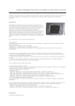
3. Ladder editor 32 basic display
The following shows the “basic” display of Ladder Editor 32. The “basic” display is
divided into two displays: “ladder preview” display and “ladder editing” display.
Editing is available as referring to the ladder image before and after the ladder
diagram in the editing line.
Fig.14 "Basic” Display
MOTOMAN ROBOTICS EUROPE
Page: 12
User’s manual Ladder Editor 32
Created: 96-01-31 Revised: 01-04-05
Doc. name: Mrs55130-ch3.fm
MOTOMAN ROBOTICS EUROPE
User’s manual Ladder Editor 32
Function
Created: 96-01-31 Revised: 01-04-05
Page: 13
Doc. name: Mrs55130-ch4.fm
4. Specifications
4.1 Function
The robot controller (YASNAC XRC) has a concurrent I/O function that processes
I/O related control independently from the manipulator, and in parallel with the
manipulator operation. Ladder Editor 32 software is used to graphically display
ladder programs with the above function as a signal connection diagram, or to
edit commands by drag and drop operation using the mouse.
■ Features of Ladder Editor 32
✔ Ladder mnemonic code can be edited with an image of a ladder diagram.
✔ With the "ladder preview" display, the entire line of the ladder program can be
easily previewed.
MOTOMAN ROBOTICS EUROPE
Page: 14
User’s manual Ladder Editor 32
Created: 96-01-31 Revised: 01-04-05
Doc. name: Mrs55130-ch4.fm
Function
✔ Simple drag and drop operation can edit connections between ladder parts.
✔ The cross reference function is enriched. Information such as relay No. use
state or the place where an arbitrary relay No. is used can be referenced easily.
✔ A history jump function is available. This function records the history of jumping
to other lines, and easily returns to the previous line before jumping.
✔ A password function is available. Since ladder editing affects the system, this
system has a user management option. The software can be set up to require a
correct password to start up the software.
✔ The printing function is enriched. The cross referenced information and the
ladder diagram can be printed. This function is useful when storing the ladder
diagram as an output document.
MOTOMAN ROBOTICS EUROPE
User’s manual Ladder Editor 32
Hardware configurations and soft-
Created: 96-01-31 Revised: 01-04-05
Page: 15
Doc. name: Mrs55130-ch4.fm
4.2 Hardware configurations and software type
■ Hardware requirements
Ladder Editor 32 operates with the configurations shown below.
OS
Japanese Microsoft Windows 95 /98 /NT4.0*
Required Memory
16 Mbytes or more
CPU
Pentium or Pentium compatible processor
Hardware Disk
Capacity for Installation
10 Mbytes or more
Disk Drive
Hard disk drive and CD-ROM drive
Display
Supported by MS-Windows
Mouse
Supported by MS-Windows
Robot Controller
YASNAC XRC
Hardware Lock Key
Used under single user registration.
If a conversion adapter is required, refer to "Hardware Lock Key"
for details.
Note!
This software is ladder editing software, not a ladder simulator.
The following devices or software are required when sending data
between the XRC and the personal computer.
✔ The floppy disk drive exclusively used for the XRC, "YASNAC FC2"
✔ The personal computer communications software, "FC1 Emulator 32"
✔ The data transmission function between the personal computer
communications software "MOTOCOM32" and the XRC
MOTOMAN ROBOTICS EUROPE
Page: 16
User’s manual Ladder Editor 32
Created: 96-01-31 Revised: 01-04-05
Doc. name: Mrs55130-ch4.fm
Hardware configurations and soft-
■ Hardware lock key
For correct operation, connect the attached hardware lock key to the personal
computer.
Two types of hardware lock keys are available :
✔ Anphenole type
✔ D-sub type
Normally, a D-sub type hardware lock key is attached.
Connection when using a PC-AT compatible personal computer
When using a PC-AT compatible personal computer such as a PC98-NX series
NEC personal computer, connect the hardware lock key to the printer port.
Connection when using a personal computer other than PC-AT
compatibles
When using an anphenole type hardware lock key, the form of printer port differs
depending on the computer model. Connect the key.
When using a D-sub type hardware lock key, install a conversion adapter between
the printer port of the personal computer and the hardware lock key. The conversion adapter should be prepared by the customer.
■ Anphenole type
■ D-sub type
MOTOMAN ROBOTICS EUROPE
User’s manual Ladder Editor 32
What is Ladder Editor 32?
Created: 96-01-31 Revised: 01-04-05
Page: 17
Doc. name: Mrs55130-ch4.fm
4.3 What is Ladder Editor 32?
The robot controller (YASNAC XRC) has a concurrent I/O function that processes
I/O related control independently from the manipulator, and in parallel with the
manipulator operation. Ladder Editor 32 software is used to graphically display
ladder programs with the above function as a signal connection diagram, or to
edit commands by drag and drop operation using the mouse.
■ Features of Ladder Editor 32
✔ Ladder mnemonic code can be edited with an image of a ladder diagram.
✔ With the "ladder preview" display, the entire line of the ladder program can be
easily previewed.
✔ Simple drag and drop operation can edit connections between ladder parts.
✔ Cross reference function is enriched. Information such as relay No. use state
or the place where an arbitrary relay No. is used can be referenced easily.
✔ History jump function is available. This function records the history of jumping
to other lines, and easily returns to the previous line before jumping.
✔ Printing function is enriched. Cross reference information can also be printed,
as well as ladder diagrams. This function is very useful when a created ladder is
stored as reference material.
MOTOMAN ROBOTICS EUROPE
User’s manual Ladder Editor 32
Page: 18
Created: 96-01-31 Revised: 01-04-05
What is Ladder Editor 32?
Doc. name: Mrs55130-ch4.fm
■ Terms
The following terms are frequently used in this manual.
Terms
Description
Ladder editor
Object of matrix composing a ladderprogram such as STR, TMR
or GRP.
Set value
Value set to ladderparts such as relay numbers, register numbers
or constants.
Line
One line indicates one section divided with OUT codes in a ladder memnemonic. Normally, there is one OUT part per line
(excluding when GRP parts are used).
MOTOMAN ROBOTICS EUROPE
User’s manual Ladder Editor 32
Created: 96-01-31 Revised: 01-04-05
Page: 19
Doc. name: Mrs55130-ch5.fm
5. Default user name and password
■ Default informations (for manager to store)
The following table shows the default user names (user IDs) and passwords at
log-ON that Ladder Editor 32 provides. "Managers" must store this information
confidentially so that it will never be known to "Operators" or "Backup Operators".
Level Name
User Name
PassWord
Manager
Admin
00000000
Operator
User
0
Backup Operator
backup
None
MOTOMAN ROBOTICS EUROPE
Page: 20
User’s manual Ladder Editor 32
Created: 96-01-31 Revised: 01-04-05
Doc. name: Mrs55130-ch5.fm
MOTOMAN ROBOTICS EUROPE
User’s manual Ladder Editor 32
Created: 96-01-31 Revised: 01-04-05
Page: 21
Doc. name: Mrs55130-ch6.fm
6. Flowchart of basic editing
The following shows the basic flowchart of ladder editing.
Fig.15 Ladder Editing Operation Flow
MOTOMAN ROBOTICS EUROPE
Page: 22
User’s manual Ladder Editor 32
Created: 96-01-31 Revised: 01-04-05
Doc. name: Mrs55130-ch6.fm
MOTOMAN ROBOTICS EUROPE
User’s manual Ladder Editor 32
How to start
Created: 96-01-31 Revised: 01-04-05
Page: 23
Doc. name: Mrs55130-ch7.fm
7. Starting and ending Ladder Editor 32
7.1 How to start
To start up Ladder Editor 32, open the [Start] menu in the Windows tool bars, and
select “Ladder Editor 32” from [Program] – [Motoman] – [Ladder Editor 32].
When this application is initially started up or when the [Manage type] is set to
“Easy Mode”, the [Input Password] dialog box for the Easy Mode (Fig. [Input
Password] Dialog Box for Easy Mode) appears. When the [Manage type] is set to
“Standard Mode”, the [Input Password] dialog box for the Standard Mode (Fig.
[Input Password] Dialog Box for Standard Mode) appears. (For details on managing user accounts, refer to “User information management”.)
Fig.16 [Input Password] Dialog Box for Easy Mode
Fig.17 [Input Password] Dialog Box for Standard Mode
MOTOMAN ROBOTICS EUROPE
Page: 24
User’s manual Ladder Editor 32
Created: 96-01-31 Revised: 01-04-05
Doc. name: Mrs55130-ch7.fm
How to start
If the “Input Password at startup application” check box is cleared in the [User
Manager] dialog box, these dialog boxes for inputting passwords do not appear.
The “Default User Names and Password List” managed and stored by the software administrator describes the “Login Name” and “Password”. This list is included with the shipment.
Input the password, and the “Startup” display for Ladder Editor 32 appears as
shown in Fig. “"Startup" Display” appears.
.
Fig.18 "Startup" Display
MOTOMAN ROBOTICS EUROPE
User’s manual Ladder Editor 32
How to end
Created: 96-01-31 Revised: 01-04-05
Doc. name: Mrs55130-ch7.fm
7.2 How to end
Selecting [File] – [Exit] in the Ladder Editor 32 menu can close the
Ladder Editor 32.
Fig.19 Exit Menu
Page: 25
MOTOMAN ROBOTICS EUROPE
Page: 26
User’s manual Ladder Editor 32
Created: 96-01-31 Revised: 01-04-05
Doc. name: Mrs55130-ch7.fm
How to end
MOTOMAN ROBOTICS EUROPE
User’s manual Ladder Editor 32
Reading Ladder Data
Created: 96-01-31 Revised: 01-04-05
Page: 27
Doc. name: Mrs55130-ch8.fm
8. Reading and storing edited ladder files
8.1 Reading Ladder Data
To perform ladder editing, read in the ladder program to be edited by Ladder Editor 32.
The following two types of files can be edited by Ladder Editor 32:
✔ Ladder program file (text file)
✔ CMOS file (binary file)
How to operate
1) Selecting [File] – [Open] menu (or
button) opens the [Open] dialog box.
Fig.20 [Open] Dialog Box
2) To read in a ladder program file, select the ladder program file and click the
[Open] button.
To read in a CMOS file, select "CMOS file (*.HEX)" from [Files of type] combo
box in [Open] dialog box in Fig. “[Open] dialog box”. When the list of CMOS.
HEX files appears, select the CMOS file to be edited, and click the [Open] button.
MOTOMAN ROBOTICS EUROPE
Page: 28
User’s manual Ladder Editor 32
Created: 96-01-31 Revised: 01-04-05
Doc. name: Mrs55130-ch8.fm
Reading several ladder files
8.2 Reading several ladder files
The Ladder Editor 32 is an MDI (Multi Document Interface) application to read in
several ladder program files simultaneously. To select the ladder program to be
edited, select the file name displayed in the [Window] menu, or select the window
with the targeted ladder program among overlapped windows by selecting [Window] - [Cascade].
In addition, the targeted ladder program can also be selected where several
editng windows are displayed and overlapped by selecting [Window] – [Cascade]
menu.
Fig.21 "Editing Window Overlapped" Display
MOTOMAN ROBOTICS EUROPE
User’s manual Ladder Editor 32
Storing edited data
Created: 96-01-31 Revised: 01-04-05
Page: 29
Doc. name: Mrs55130-ch8.fm
8.3 Storing edited data
When ladder editing is completed, store the information in a file. Before storing,
compile the data when a ladder was edited by Ladder Editor 32.
Unless compiled, data may not be stored completely.
How to Operate
1) Selecting [File] – [Save] stores the overwritten data on an existing file.
2) Selecting [File] – [Save As] displays the [Save As] dialog box. Set an arbitrary
file name to the data to be stored.
To store the file, the following three types of file forms are available,
depending on the method used to read in a file.
a) Storing when a Ladder Program File (CIOPRG.LST) is Open.
When a ladder program file is read in, only a ladder program file (text file) can
be stored in an output file form.
b) Storing when a CMOS File (CMOS.HEX) is Open.
When a CMOS file is read in, the data can be stored in the two types of file
forms, a ladder program file (text file) and a CMOS file (binary file), as an output file.
c) Storing a Ladder Program that is Being Edited.
A ladder program being edited cannot be stored if it has a detected error, even
if compiled. The ladder program being edited can be stored as a work file. For
details, refer to paragraph "Work File Forced Output Function".
MOTOMAN ROBOTICS EUROPE
Page: 30
User’s manual Ladder Editor 32
Created: 96-01-31 Revised: 01-04-05
Doc. name: Mrs55130-ch8.fm
Storing edited data
MOTOMAN ROBOTICS EUROPE
User’s manual Ladder Editor 32
Created: 96-01-31 Revised: 01-04-05
Page: 31
Doc. name: Mrs55130-ch9.fm
9. Creating a ladder diagram
To create a new ladder program, use the standard ladder program as the base for
editing. The standard ladder program is supplied as a template.
How to Operate
1) Selecting [File] – [New] displays the dialog box shown in fig.
Fig.22 [Select standard ladder template] Dialog Box
2) Select the template to be set and click the [Open] button.
MOTOMAN ROBOTICS EUROPE
Page: 32
User’s manual Ladder Editor 32
Created: 96-01-31 Revised: 01-04-05
Doc. name: Mrs55130-ch9.fm
MOTOMAN ROBOTICS EUROPE
User’s manual Ladder Editor 32
Ladder parts specifications
Created: 96-01-31 Revised: 01-04-05
Page: 33
Doc. name: Mrs55130-ch10.fm
10. Editing a ladder diagram
All ladder diagrams are edited in the "Basic" Display shown in fig. ““Ladder Preview” display”.
10.1 Ladder parts specifications
The Ladder Editor 32 supports the ladder parts corresponding to the new ladder
codes employed for the XRC.
For the details on such ladder parts, refer to the [Ladder Parts Specifications] of
[Help] menu.
10.2 Selecting a ladder edited line
A ladder diagram is edited in the "ladder editing" display, and the line to be displayed in the "ladder editing" display is selected in the "ladder preview" display
(Fig. below). In the "ladder preview" display, images of the ladder diagrams of all
the lines can be viewed set in the current ladder section (either system section or
user section).
Fig.23 "Ladder preview" display
To refer to the ladder image of a line that is not displayed on the display, scroll
using the scroll bar.
In the "ladder preview" display, right-click the mouse to select the line to be edited
and the "ladder editing" display with the ladder diagram of the selected line will
appear.
MOTOMAN ROBOTICS EUROPE
Page: 34
User’s manual Ladder Editor 32
Created: 96-01-31 Revised: 01-04-05
Adding new ladder parts
Doc. name: Mrs55130-ch10.fm
10.3 Adding new ladder parts
New ladder parts can be added when editing a ladder diagram.
Add ladder parts in the following manner.
How to operate
1) Enter the parts addition mode (select parts to be added).
Selecting [Tool] – [Parts] displays the list of ladder parts to be added. Then
select the ladder parts. Or select the parts to be added from the ladder parts
tool bar (refer to the paragraph "Ladder Parts Tool Bar").
✔ Example) Adding the ladder parts of the NC contact
Select [Tool] – [Parts] – [STR-NOT], or tool bar
.
2) Set new parts on the matrix to be added in the "ladder editing" display.
When the ladder parts to be added are determined, the mouse form changes
in the "ladder editing" display. The selected ladder parts appear at the side of
the mouse pointer. Left-click on the matrix location where the ladder parts are
to be added.
Fig.24 Addition of ladder parts
"????" may appear for the added ladder parts. This is because the relay No. or
register No. is not set for these ladder parts, and it is not an error. Set the relay
No. or register No.. For the setting of the relay Nos. or register Nos., refer to
the paragraph "Setting Relay No., Register No. and Constants".
10.4 Deleting ladder parts
Delete the ladder parts in the following manner.
How to operate
1) Enter the parts deletion mode.
Select [Tool] – [Mode] – [Delete Parts], or select
bar (refer to "Parts Control Tool Bar").
from the parts control tool
2) Select the ladder parts to be deleted in the "ladder editing" display.
Left-click on the matrix location where the ladder parts are to be deleted in the
"ladder editing" display.
MOTOMAN ROBOTICS EUROPE
User’s manual Ladder Editor 32
Connecting and disconnecting lines
Created: 96-01-31 Revised: 01-04-05
Page: 35
Doc. name: Mrs55130-ch10.fm
10.5 Connecting and disconnecting lines between ladder parts
Ladder parts on a certain matrix are connected to ladder parts on another matrix
with a line. The connection method of the line determines the ladder process. The
following paragraph describes how to connect and disconnect the line between
ladder parts.
10.5.A Connecting with a Line
Connect ladder parts with a line in the following manner.
How to operate
1) Left-click the mouse on the first ladder part.
2) While pressing the mouse, drag the mouse to the second ladder part.
3) Release the left button at the second ladder part.
Two parts are connected by a drag and drop operation.
Fig.25 Line connection process
■ Ladder parts connection terminals
Ladder parts have IN and OUT terminals. A connecting line connects the IN and
OUT terminals. A drop and drag operation determines which are IN and which are
OUT terminals and connects them automatically.
However, when two connection ladder parts are placed vertically as shown in Fig.
below, the user must decide to connect the IN or OUT side.
Fig.26 When parts are placed vertically
In Fig. “Connection on inside”, the mouse pointer is dragged from the center of a
ladder part and dropped on the IN side of the other part, to make the connecting
line on the IN side.
Dropping on the IN side makes a line which connects to the IN side of the other
ladder part. On the other hand, dropping on the OUT side makes a line which
connects to the other OUT side.
MOTOMAN ROBOTICS EUROPE
Page: 36
User’s manual Ladder Editor 32
Created: 96-01-31 Revised: 01-04-05
Doc. name: Mrs55130-ch10.fm
Connecting and disconnecting lines
Fig.27 Connection on inside
10.5.B Disconnecting two parts
Erase the line between ladder parts to disconnect them in the following manner.
How to operate
1) Right-click the mouse on the first ladder part.
2) While pressing the mouse, drag the mouse to the second ladder part.
3) Release the right button at the second ladder part.
Two parts are disconnected by a right-click, drag and drop operation.
Fig.28 Disconnection Process
MOTOMAN ROBOTICS EUROPE
User’s manual Ladder Editor 32
Setting relay no., register no. and
Created: 96-01-31 Revised: 01-04-05
Page: 37
Doc. name: Mrs55130-ch10.fm
10.6 Setting relay no., register no. and constants
Relay No., register No. and constants can be set for each ladder parts. Set these
values in the following manner.
How to operate
1) Enter the set value input mode.
Select [Tool] – [Mode] – [Input No.], or select
from the parts control tool
bar (refer to paragraph "Parts control tool bar").
2) Select the ladder parts to which the set values are input in the "ladder editing"
display.
Left-click the mouse on the ladder parts in the "ladder editing" display, and
the "set value input" dialog box appears.
Fig.29 [Input Value] Dialog Box
Note!
The number of setting items in the [Input Value] dialog box differs
depending on the ladder parts.
3) Input the set values.
Select the type of the set value in the combo box of the [Input Value] dialog
box, and then input a value suitable for the type of the set value.
Click the [OK] button to set the values.
■ Setting Values Using a Pop-up Menu
Set values can also be set in the following manner using a pop-up menu. The
pop-up menu appears by right-clicking the mouse.
How to operate
1) Right-click the mouse on the ladder parts to which the set values are input,
and select the pop-up menu.
Right-click the mouse on the ladder parts to which the set values are input in
the "ladder editing" display, and the pop-up menu appears. Select the [Input
No.], and the [Input Value] dialog box appears.
2) Input the set values.
Input the set values in the [Input Value] dialog box.
MOTOMAN ROBOTICS EUROPE
Page: 38
User’s manual Ladder Editor 32
Created: 96-01-31 Revised: 01-04-05
Doc. name: Mrs55130-ch10.fm
Inputting relay no. and register no.
10.7 Inputting relay no. and register no. names
Names can be set for the relay Nos. and register Nos.. When editing name, a new
name can be input or name information read from the external name file can be
edited. Set the name for a relay No. or a register No. in the following manner.
How to operate
1) Enter the name input mode.
Select [Tool] – [Mode] – [Input Relay Name], or select
trol tool bar (refer to "Parts control tool bar").
from the parts con-
2) Select the ladder parts where the number of the name to be selected is set.
Left-click the mouse on the ladder parts where the number of the name to be
selected is set in the "ladder editing" display, and the [Input name] dialog box
appears.
Fig.30 [Input name] Dialog Box
The relay No. or register No. appears in the No. selection list box as shown below.
✔ Relay No. : #xxxx, W#xxxx
✔ Register No. : Mxxx
Note!
Some ladder parts have several relay Nos. or register Nos. In such a
case, several numbers appear in the No. selection list box.
Verify that the targeted relay Nos. or register Nos. appear and are selected in the
relay No. selection list box.
3) Set the name.
Two types of names, a short name and a long name can be used. They are
treated as follows with Ladder Editor 32.
Short name:
Appears overlapped on the relay No. or register No. of the ladder
diagram in the "ladder editing" display.
(Refer to "Switching short name display/non-display".)
Long name:
Appears in the column of OUT relay names in the "ladder editing"
display, and in the row of output signal names in the "ladder
preview" display.
When setting is completed, be sure to click the [Update] button. This
button records the setting information.
MOTOMAN ROBOTICS EUROPE
User’s manual Ladder Editor 32
Inserting editing matrix row and line
Created: 96-01-31 Revised: 01-04-05
Page: 39
Doc. name: Mrs55130-ch10.fm
■ Setting names using a pop-up menu
Names can be also set in the following manner using the pop-up menu.
How to operate
1) Select the ladder parts where the relay No. or register No. of the name to be
edited is set.
Right-click the mouse on the ladder parts where the relay No. or register No.
of the name to be edited is set in the "ladder editing" display, and the pop-up
menu appears. Select the [Input Name], the [Input name] dialog box appears.
2) Edit the name.
Edit the displayed name for a relay No. or register No. in the [Input name] dialog box.
10.8 Inserting editing matrix row and line
Even though new ladder parts are to be inserted immediately before the ladder
parts that have already been set, there may be no matrix for insertion as shown in
the following diagram.
Fig.31 When no space for matrix
In this case, insert a line (or a row) to secure the matrix where the ladder parts are
to be inserted.
10.8.A Inserting a row
Insert a row in the following manner.
How to operate
1) Enter the row insertion mode.
Select [Tool] – [Mode] – [Row control] – [Insert Row].
Or select
from the parts control tool bar (refer to "Parts Control Tool Bar").
2) Specify the matrix where a row is to be inserted.
Left-click the mouse on the matrix where a row is to be inserted.
Fig.32 Result of Row Insertion
MOTOMAN ROBOTICS EUROPE
Page: 40
User’s manual Ladder Editor 32
Created: 96-01-31 Revised: 01-04-05
Doc. name: Mrs55130-ch10.fm
Inserting editing matrix row and line
■ Row insertion disabled pattern
A row cannot be inserted if even one part exists in the column just before the
last column on the right after the second line of the matrix in the "ladder editing"
display.
Fig.33 Disabled row insertion
10.8.B Inserting a Line
Insert a line in the following manner.
How to operate
1) Enter the line insertion mode.
Select [Tool] – [Mode] – [Column control] – [Insert Column].
Or select
from the parts control tool bar (refer to "Parts Control Tool Bar").
2) Specify the matrix where a line is to be inserted.
Left-click the mouse on the matrix where a line is to be inserted.
Fig.34 Result of line insertion
MOTOMAN ROBOTICS EUROPE
User’s manual Ladder Editor 32
Inserting editing matrix row and line
Created: 96-01-31 Revised: 01-04-05
Page: 41
Doc. name: Mrs55130-ch10.fm
■ Line insertion disabled pattern
A line cannot be inserted if even one part exists in the lowest line of the matrix in
the "ladder editing" display.
Fig.35 Disabled line insertion
MOTOMAN ROBOTICS EUROPE
Page: 42
User’s manual Ladder Editor 32
Created: 96-01-31 Revised: 01-04-05
Doc. name: Mrs55130-ch10.fm
Deleting Editing Matrix Row and
10.9 Deleting Editing Matrix Row and Line
Unnecessary rows or lines can be deleted.
10.9.A Deleting a Row
Delete a row in the following manner.
How to operate
1) Enter the row deletion mode.
Select [Tool] – [Mode] – [Row control] – [Delete Row].
Or select
from the parts control tool bar (refer to "Parts control tool bar").
2) Specify the matrix where a row is to be deleted.
Left-click the mouse on the matrix where a row is to be deleted.
Fig.36 Result of row deletion
Note!
Deletion of a row deletes all the ladder parts that are set to the row to
be deleted.
MOTOMAN ROBOTICS EUROPE
User’s manual Ladder Editor 32
Clearing Displays
Created: 96-01-31 Revised: 01-04-05
Page: 43
Doc. name: Mrs55130-ch10.fm
10.9.B Deleting a Line
Delete a line in the following manner.
How to operate
1) Enter the line deletion mode.
Select [Tool] – [Mode] – [Column control] – [Delete column].
Or select
from the parts control tool bar (refer to "Parts control tool bar").
2) Specify the matrix where a line is to be deleted.
Left-click the mouse on the matrix where a line is to be deleted.
Fig.37 Result of line deletion
Note!
Deletion of a line deletes all the ladder parts set to the line
to be deleted.
10.10 Clearing Displays
The contents of the "ladder editing" display can be cleared when editing. This
function is useful when the current display is to be reedited from the beginning.
How to operate
Select [Edit] – [Clear]. Or select
(refer to " Parts Control Tool Bar").
from the parts control tool bar
MOTOMAN ROBOTICS EUROPE
Page: 44
User’s manual Ladder Editor 32
Created: 96-01-31 Revised: 01-04-05
Doc. name: Mrs55130-ch10.fm
Clearing Displays
MOTOMAN ROBOTICS EUROPE
User’s manual Ladder Editor 32
Created: 96-01-31 Revised: 01-04-05
Page: 45
Doc. name: Mrs55130-ch11.fm
11. Inserting a new line
A new line is inserted into an arbitrary line. Since default values are set to the new
line, change the values to the correct ladder information.
The new line is inserted into the next line of the line selected in the ladder preview
display.
How to operate
1) Select [Edit] – [Insert new line], or select
(refer to "Main tool bar").
from the main tool bar
Fig.38 Inserting new line
MOTOMAN ROBOTICS EUROPE
Page: 46
User’s manual Ladder Editor 32
Created: 96-01-31 Revised: 01-04-05
Doc. name: Mrs55130-ch11.fm
MOTOMAN ROBOTICS EUROPE
User’s manual Ladder Editor 32
Changing an edited ladder line
Created: 96-01-31 Revised: 01-04-05
Page: 47
Doc. name: Mrs55130-ch12.fm
12. Line operation of ladder diagram
Be sure to select [Line Alt] or [Line Insert] for the contents edited in the "ladder
editing" display before editing another line. Without this operation, the contents
edited immediately before will be deleted. Ladder Editor 32 checks the ladder
information that is being currently edited when another line appears. If the [Line
Alt] or [Line Insert] is not selected, an editing confirmation message appears.
(Refer to "Automatic updating function".)
Fig.39 [Confirmation] Dialog Box
Normally, the operator uses the menu or tool button to perform [Line Alt] or [Line
Insert].
12.1 Changing an edited ladder line
Overwrite the contents edited in the "ladder editing" display on the line currently
being edited, in the following manner.
How to operate
1) Select [Edit] – [Line control] – [Line Alt], or select
(refer to "Main tool bar").
from the main tool bar
12.2 Inserting an Edited Ladder Line
Insert the contents edited in the "ladder editing" display into the next line of the
line currently being edited, in the following manner. Therefore, the ladder data
after the inserting line will be shifted backward.
How to operate
1) Select [Edit] – [Line control] – [Line Insert], or select
(refer to "Main tool bar").
from the main tool bar
MOTOMAN ROBOTICS EUROPE
Page: 48
User’s manual Ladder Editor 32
Created: 96-01-31 Revised: 01-04-05
Doc. name: Mrs55130-ch12.fm
Inserting an Edited Ladder Line
MOTOMAN ROBOTICS EUROPE
User’s manual Ladder Editor 32
Cutting a ladder diagram line
Created: 96-01-31 Revised: 01-04-05
Page: 49
Doc. name: Mrs55130-ch13.fm
13. Cutting, copying and pasting lines
13.1 Cutting a ladder diagram line
Cut the line selected in the "ladder preview" display. The ladder information of the
cut line can be pasted to another line by pressing [Paste] or [Insert/Paste].
How to operate
1) Select the line to be cut in the "ladder preview" display, and select [Edit] –
[Cut]. Or select
from the main tool bar (refer to "Main tool bar").
2) To select several lines simultaneously, hold down the [SHIFT] or [CTRL] key
when selecting lines.
13.2 Copy a ladder diagram line
Copy the line selected in the "ladder preview" display.
The ladderinformationof the copied line can be pasted onto another line by pressing [Paste] or [Insert/Paste].
How to operate
1) Select the line to be copied in the "ladder preview" display. Then select [Edit] –
[Copy] menu. Or select
from the main tool bar (refer to “Main tool bar").
2) To select several lines simultaneously, hold down the [SHIFT] or [CTRL] key
when selecting lines.
13.3 Pasting a ladder diagram line
Paste the cut or copied contents of the line by pressing [Cut] or [Copy] over the
line selected in the "ladder preview" display.
When several ladder list files are open simultaneously, the ladder diagram can be
pasted onto another ladder list file.
How to operate
Select the line to be pasted in the "ladder preview" display, and select [Edit] –
[Paste]. Or select
from the main tool bar (refer to "Main tool bar").
Note!
This function is disabled if several lines were cut or copied by
pressing [Cut] or [Copy] in the operation immediately before.
After selecting only one line and pressing [Cut] or [Copy], try pasting
again.
MOTOMAN ROBOTICS EUROPE
Page: 50
User’s manual Ladder Editor 32
Created: 96-01-31 Revised: 01-04-05
Doc. name: Mrs55130-ch13.fm
Inserting and pasting a ladder dia-
13.4 Inserting and pasting a ladder diagram line
Insert the cut or copied contents of the line into the line selected in the "ladder preview" display. Therefore, the ladder data after the inserting/pasting line will be shifted backward.
When several ladder list files are open simultaneously, the ladder diagram can be
inserted and pasted onto another ladder list file.
How to operate
1) Select the line to be inserted and pasted in the "ladder preview" display. Then
select [Edit] – [Insert Paste]. Or select
from the main tool bar.
(Refer to "Main tool bar").
MOTOMAN ROBOTICS EUROPE
User’s manual Ladder Editor 32
Created: 96-01-31 Revised: 01-04-05
Page: 51
Doc. name: Mrs55130-ch14.fm
14. Compiling edited contents
Be sure to compile the ladder information of each line after editing.
Compiling performs final checking such as the relay No. overlapping check, etc.
to load the information to the controller.
How to operate
Select [Edit] – [Compile], or select
(Refer to "Main Tool Bar").
from the main tool bar.
Note!
Without this operation, the edited data cannot be correctly stored.
Since compiling processes the system section and the user section
of the ladder program, it is unnecessary to change to a system ladder
or a user ladder.
MOTOMAN ROBOTICS EUROPE
Page: 52
User’s manual Ladder Editor 32
Created: 96-01-31 Revised: 01-04-05
Doc. name: Mrs55130-ch14.fm
MOTOMAN ROBOTICS EUROPE
User’s manual Ladder Editor 32
Printing a ladder diagram
Created: 96-01-31 Revised: 01-04-05
Page: 53
Doc. name: Mrs55130-ch15.fm
15. Printing
15.1 Printing a ladder diagram
Print an image of a ladder diagram. For the ladder program to be printed, the
line Nos. of other lines referring to the OUT terminal relay Nos. appear.
The information of the reference lines appears as the system section and user section
together.
How to Operate
1) Select [File] – [Print] – [Ladder Image] – [System Ladder (or User Ladder)].
Fig.40 Ladder image printing
MOTOMAN ROBOTICS EUROPE
Page: 54
User’s manual Ladder Editor 32
Created: 96-01-31 Revised: 01-04-05
Printing relay no. using list
Doc. name: Mrs55130-ch15.fm
15.2 Printing relay no. using list
Print the list of used relay Nos. and the line Nos. referring to each relay No. in a list. List
information of the reference lines appears as the system section and user section
together.
How to operate
1) Select [File] – [Print] – [Relay No. use line list] –
[System Ladder (or User Ladder)].
Fig.41 Printing relay no. list
MOTOMAN ROBOTICS EUROPE
User’s manual Ladder Editor 32
Printing register no. using list
Created: 96-01-31 Revised: 01-04-05
Page: 55
Doc. name: Mrs55130-ch15.fm
15.3 Printing register no. using list
Print the list of used register Nos. and line Nos. referring to each register No. in a list.
List information of the reference lines appears as the system section and user section
together.
How to Operate
1) Select [File] – [Print] – [Register No. use line list] –
[System Ladder (or User Ladder)].
Fig.42 Printing register no. list
MOTOMAN ROBOTICS EUROPE
Page: 56
User’s manual Ladder Editor 32
Created: 96-01-31 Revised: 01-04-05
Printing relay no. use state
Doc. name: Mrs55130-ch15.fm
15.4 Printing relay no. use state
Print the relay No. use state in the "matrix" display.
How to Operate
1) Select [File] – [Print] – [Relay No. use state].
Relay Nos. for the system section and user section appear together, indicated
by the following symbols.
✔ S: Relay Nos. used in a system section
✔ U: Relay Nos. used in a user section
✔ B: Relay Nos. used in both system and user sections
2) A relay No. in a matrix is regarded as YYYYX when the vertical is "YYYY" and
the horizontal axis value is "X".
Fig.43 Printing relay no. use state
MOTOMAN ROBOTICS EUROPE
User’s manual Ladder Editor 32
Printing User Alarms and User Mes-
Created: 96-01-31 Revised: 01-04-05
Page: 57
Doc. name: Mrs55130-ch15.fm
15.5 Printing User Alarms and User Messages
Print the lists of user alarms and user messages.
How to operate
1) Select [File] – [Print] – [User alarm user message].
Fig.44 Printing user alarm list
MOTOMAN ROBOTICS EUROPE
Page: 58
User’s manual Ladder Editor 32
Created: 96-01-31 Revised: 01-04-05
Doc. name: Mrs55130-ch15.fm
Printing User Alarms and User Mes-
Fig.45 Printing user message list
The following describes the items of printed information. User alarms and user
messages can be printed. Since each display item is the same, this paragraph
describes printing of the user alarm list as an example.
MOTOMAN ROBOTICS EUROPE
User’s manual Ladder Editor 32
Printing User Alarms and User Mes-
Created: 96-01-31 Revised: 01-04-05
Page: 59
Doc. name: Mrs55130-ch15.fm
■ User alarm system section and user section
A user alarm can be roughly classified as a system section that the system uses
or a user section that the user can define freely. When printing, this information
appears as the following word.
[User Alarm(****** Section)]
■ User alarm selection relay no. information
Relay No. information is displayed to help select a used user alarm. A user alarm
is specified by turning the following four relays ON/OFF.
4020, 4021, 4022, 4023
When printing, this information appears as the following word:
[Type Selection Signal Relay No.]
When each relay No. is actually used in a code, the line No. appears:
■ User alarm display relay no. information
Relay No. information which becomes a trigger to help display a user alarm
appears. The relay No. that becomes a display trigger is 4010.
When printing, this information appears with the following word.
[Request Signal Relay No.]
When each relay No. is actually used in a code, the line No. appears.
MOTOMAN ROBOTICS EUROPE
Page: 60
User’s manual Ladder Editor 32
Created: 96-01-31 Revised: 01-04-05
Doc. name: Mrs55130-ch15.fm
Printing User Alarms and User Mes-
MOTOMAN ROBOTICS EUROPE
User’s manual Ladder Editor 32
Transferring Ladder Diagrams to a
Created: 96-01-31 Revised: 01-04-05
Page: 61
Doc. name: Mrs55130-ch16.fm
16. Transferring printing information to a text file
16.1 Transferring Ladder Diagrams to a Text File
Transfers an image of a ladder diagram to a text file.
[How to Operate]
Select [File] – [Output Text] – [Ladder Image] – [System Ladder (or User Ladder)].
16.2 Transferring Used Relay No. Lists to a Text File
Transfers the lists of relay Nos. used and the line Nos. referring to each relay No. to a
text file. The system section and the user section are transferred together in the list of
reference lines.
[How to Operate]
Select [File] – [Output Text] – [Relay No. use line list] – [System Ladder (or User Ladder)].
16.3 Transferring Used Register No. Lists to a Text File
Transfers the lists of register Nos. used and the line Nos. referring to each register No.
to a text file. The system section and the user section are transferred together in the
list of reference lines.
[How to Operate]
Select [File] – [Output Text] – [Register No. use line list] – [System Ladder (or User
Ladder)].
16.4 Transferring Relay No. Use State to a Text File
Transfers the relay number use state to the text file in a "matrix" display.
[How to Operate]
Select [File] – [Output Text] – [Relay No. use state].
16.5 Transferring User Alarms and User Messages to a Text File
Transfers the user alarms and user messages to a text file.
[How to Operate]
Select [File] - [Output text] - [User alarm message]
MOTOMAN ROBOTICS EUROPE
Page: 62
User’s manual Ladder Editor 32
Created: 96-01-31 Revised: 01-04-05
Doc. name: Mrs55130-ch16.fm
Transferring User Alarms and User
MOTOMAN ROBOTICS EUROPE
User’s manual Ladder Editor 32
Ladder name and system register
Created: 96-01-31 Revised: 01-04-05
Page: 63
Doc. name: Mrs55130-ch17.fm
17. Header information
17.1 Ladder name and system register editing
Edit the ladder program names and system registers.
How to Operate
1) Select [View] – [Header Information], or select
(Refer to "Main tool bar").
from the main tool bar.
Fig.46 [Header information] dialog box
a) [Name] combo box.
Selects a ladder name. Normally, select one from the list in the combo box. A
name can be entered directly. However, an improper name interrupts the loading to the controller.
b) System registers.
Sets the number of system registers.
MOTOMAN ROBOTICS EUROPE
Page: 64
User’s manual Ladder Editor 32
Created: 96-01-31 Revised: 01-04-05
Doc. name: Mrs55130-ch17.fm
Ladder name and system register
MOTOMAN ROBOTICS EUROPE
User’s manual Ladder Editor 32
User alarm and user message in
Created: 96-01-31 Revised: 01-04-05
Page: 65
Doc. name: Mrs55130-ch18.fm
18. User alarm and user message information
Edit the user alarms and user messages.
How to Operate
1) Select [View] – [Message Information], or select
(Refer to "Message tool bar").
from the main tool bar.
Fig.47 [Message Information] Dialog Box
Click the tag to select the user alarm and user message.
■ Language combo box
Each message has a first and a second languages. Select your desired language
from the language combo box.
■ Editing area
Click the message to be edited in the message list, and the same message
appears in the editing area. Edit the message in this area. When editing is
completed, press the [Change] button.
18.1 User alarm and user message in system section
If the user account level does not reach the management level, only the information in the user section appears in the message list. To display or edit the information in the system section, change the user account level. (Refer to "User
information management".)
MOTOMAN ROBOTICS EUROPE
Page: 66
User’s manual Ladder Editor 32
Created: 96-01-31 Revised: 01-04-05
Doc. name: Mrs55130-ch18.fm
User alarm and user message in
MOTOMAN ROBOTICS EUROPE
User’s manual Ladder Editor 32
User ladder and system ladder
Created: 96-01-31 Revised: 01-04-05
Page: 67
Doc. name: Mrs55130-ch19.fm
19. System ladders and user ladders
19.1 User ladder and system ladder
A ladder program has a system ladder in the system Section and a user ladder in
the user section. Because the manipulator may not move properly unless the system section is correctly edited, general users cannot edit the system section as
well as the XRC. General users can edit only in the user ladder section. (Contact
your Motoman representative when editing in the system section of the ladder
program is required.)
MOTOMAN ROBOTICS EUROPE
Page: 68
User’s manual Ladder Editor 32
Created: 96-01-31 Revised: 01-04-05
Doc. name: Mrs55130-ch19.fm
User ladder and system ladder
MOTOMAN ROBOTICS EUROPE
User’s manual Ladder Editor 32
What is name file?
Created: 96-01-31 Revised: 01-04-05
Page: 69
Doc. name: Mrs55130-ch20.fm
20. Name file
20.1 What is name file?
Name file is a name information file to add a name to a relay No. or register No.
used in the ladder program. (For the format of the name file, refer to "Name file
format".)
20.2 Reading name file
Name file is read in at either one of the following times.
✔ When a ladder program file or CMOS file is open
✔ When a name file is read in from the menu
When a ladder program file or CMOS file is open, the name file is read in at the
same time as the ladder program file or CMOS file. When a name file is read in
from the menu, any existing name file can be read in whenever necessary.
The name file is saved in the same folder as the ladder program file or the CMOS
file. (Even if a name file has not been prepared, the ladder program can still be
edited. Refer to “Reading name file automatically”.)
■ Reading Name File Automatically (With Name File)
When reading in a ladder program file or a CMOS file, Ladder Editor 32 automatically reads in the name file, too. The name file automatically read in is determined
by the ladder name of the ladder program used as a keyword (refer to "Ladder
Name and System Register Editing".
Example:
Ladder program name : ARCWELD
Read in file name : ARCWELD.NAM
■ Reading Name File Automatically (Without Name File)
If the desired name file is not available when automatically reading the name file,
Ladder Editor 32 performs the operation in the following manner.
1) Selects a file suitable for the desired ladder program from the name template
file prepared in default.
2) Copies the selected template file to the same directory as the ladder program
file.
3) Reads in the copied template file as a name file.
In this case, Ladder Edit 32 refers to the ladder names to be read in to select the
template file.
MOTOMAN ROBOTICS EUROPE
Page: 70
User’s manual Ladder Editor 32
Created: 96-01-31 Revised: 01-04-05
Doc. name: Mrs55130-ch20.fm
Reading name file
However, when the user changes the ladder name of the ladder program file, Ladder Editor 32 may not find any file name that coincides with the ladder name template file. In such a case, the [Select name template] dialog box appears.
Fig.48 [Select Name Template] Dialog Box
Select the template suitable for the desired ladder program. Clicking the [Cancel]
button stops the automatic reading of the name file.
The following shows the simple flowchart of the automatic reading.
MOTOMAN ROBOTICS EUROPE
User’s manual Ladder Editor 32
Storing Name File
Created: 96-01-31 Revised: 01-04-05
Page: 71
Doc. name: Mrs55130-ch20.fm
20.3 Storing Name File
Store the edited name information by one of the following two methods.
■ Stores it manually
How to operate 1
1) Select [File] – [Save relay name]. When the [Save As] dialog box appears,
input an arbitrary name for the name file to store it. Normally, the file name is
stored in the following format.
Ladder name. NAM
Example: ARCWELD.NAM
2) For the ladder names, refer to "Header information".
■ Stores it automatically
How to operate 2
Setting the option stores the name file automatically. Refer to " Automatic storing
function of name file".
20.4 Name Template File
Name template file is installed automatically when Ladder Editor 32 is setup. The
following folder is created in the folder where the Ladder Editor 32 execution
module exists, and the name template file is stored in this folder.
“Template”
MOTOMAN ROBOTICS EUROPE
Page: 72
User’s manual Ladder Editor 32
Created: 96-01-31 Revised: 01-04-05
Doc. name: Mrs55130-ch20.fm
Name Template File
MOTOMAN ROBOTICS EUROPE
User’s manual Ladder Editor 32
Created: 96-01-31 Revised: 01-04-05
Page: 73
Doc. name: Mrs55130-ch21.fm
21. Relay/register name list display function
The relay name list display function and register name list display function can
display the name list for all relay Nos. and register Nos.. All the data of the read-in
name files can be cross referenced. This "list display" dialog box has the editing
function. The name information of an arbitrary relay or register No. can be edited.
■ How to operate “relay name list" display
1) Select [View] – [Relay No. Name list]. The [Relay name list] dialog box
appears as in fig. (Some machines take time to display it.)
Fig.49 [Relay Name List] Dialog Box
By selecting any desired relay No. from the list, the currently set data appears in
the [No.], [Short Name] and [Long Name] columns. Edit the data here. After editing, click the [Update] button to register the edited data.
If the [Short Name] and the [Long Name] are similar for two or more relay Nos.,
change only the [No.], and then click the [Update] button. The name previously
entered will remain. Because the names are similar, change only the characters
that are different. The entire name does not have to be re-entered.
MOTOMAN ROBOTICS EUROPE
Page: 74
User’s manual Ladder Editor 32
Created: 96-01-31 Revised: 01-04-05
Doc. name: Mrs55130-ch21.fm
■ How to operate "register name list" display
1) Select [View] – [Register Name List]. The [Register name list] dialog box
appears as in fig. (Some machines take time to display it.)
Fig.50 [Register Name List] Dialog Box
2) Editing procedure is the same as that of "Relay No. List" Display.
Normally, edit a relay or register name by opening the [Input name] dialog box on
the ladder diagram. However, relay Nos. or register Nos. not used for ladder diagrams cannot be less of edited. These lists can be used to edit the names for all
the relay or register Nos. regardless whether or not they are used on the ladder
diagram.
MOTOMAN ROBOTICS EUROPE
User’s manual Ladder Editor 32
Line No. Search Jump
Created: 96-01-31 Revised: 01-04-05
Page: 75
Doc. name: Mrs55130-ch22.fm
22. Line jump function
The line jump function searches for and jumps to the line with the keyword.
22.1 Line No. Search Jump
This function jumps to the specified line No.
How to operate
1) Select [Edit] – [Find Line No.], or select
(black) from the search jump tool
bar (refer to "Search jump tool bar").
When the dialog box shown in fig. below appears, enter the line No. to jump
and click the [OK] button.
Fig.51 "Line Search" Dialog Box
22.2 Parts set value search jump
This function searches for values such as relay Nos., register Nos., and constants
set to the ladder parts, and then jumps to the line with the set values.
How to operate
1) Select [Edit] – [Find setting value] – [Find], or select
(brown) from the
search jump tool bar (refer to "Search Jump Tool Bar").
2) When the dialog shown in fig. below appears, enter the type of the value and
the set value to be searched and click the [OK] button.
Fig.52 "Set Value Searching" Dialog Box
■ Previous/Next Search Jump
Previous search and next search functions can be used for searching for parts set
values only.
How to operate
1) For a previous search, select [Edit] – [Find setting value] – [Back find].
Or select
Tool Bar").
(brown) from the search jump tool bar (refer to "Search Jump
2) For next search, select [Edit] – [Find setting value] – [Next Find].
Or select
(brown) from the search jump tool bar.
MOTOMAN ROBOTICS EUROPE
Page: 76
User’s manual Ladder Editor 32
Created: 96-01-31 Revised: 01-04-05
Doc. name: Mrs55130-ch22.fm
OUT parts relay no. search jump
Previous Search
Previous search is a function to search for the set value in front of the current line
(in the direction of smaller line No.).
Next Search
Next search is a function to search for the set value behind the current line (in the
direction of greater line No.).
Unless new set values are entered by pressing [Edit]-[Find setting value]-[Back
find] or [Next find], the set values to be searched for do not change.
This function can be used to easily know where and how the set values are used.
22.3 OUT parts relay no. search jump
The OUT parts relay No. search jump function searches only for the relay No. set
to the OUT parts of the ladder parts and jumps there. Other ladder parts can not
be searched for.
How to operate
1) Select [Edit] – [Find OUT Relay No.]. Or select
bar (refer to "Search Jump Tool Bar").
from the search jump tool
2) When the dialog box shown in fig. below appears, input the relay No. to be
searched for and click the [OK] button.
Fig.53 "Line Search" Dialog Box
This function can be used to analyze the conditions in which the relay used in the
line turns ON retroactively.
22.4 History Jump
The history jump function stores the line jump functions used in the past as the
history and easily returns to the previous jump source.
This function does not exist as a menu item; Only available as a tool bar button.
How to operate
1) Select
or
from the search jump tool bar.
(Refer to "Search jump tool bar").
This history jump button can freely move to the line registered as jump history.
Normally, this function is disabled. When jumps are performed, this function becomes enabled.
■ Application
An example of its most useful application is used together with "OUT parts relay
No. search jump". When searching for certain relay No. ON/OFF conditions using
the "OUT parts relay No. search jump", a search jump may also be performed in
the further advanced lines for retroactive analyses. After completion of analysis,
this history jump function can easily return to the previous line.
MOTOMAN ROBOTICS EUROPE
User’s manual Ladder Editor 32
Ladder Parts Set Value and refe-
Created: 96-01-31 Revised: 01-04-05
Page: 77
Doc. name: Mrs55130-ch23.fm
23. Cross reference function
23.1 Ladder Parts Set Value and reference line list display
function
The ladder parts set value and reference line list display function displays on
which line and for which ladder parts the specified set values are used.
How to operate
1) Select [View] – [Value Reference line list]. The dialog box shown
in fig. appears.
Fig.54 [Input Value] Dialog Box
2) After inputting the targeted set value type and the value, click the [OK] button.
The [Reference line list] dialog box appears.
Fig.55 [Reference Line List] Dialog Box
■ [Value] (Reference Data) List Box
The list contains the set values to be searched for. Normally, there is only one
item. However, since more than two items may appear occasionally, select one.
■ [Parts] Tree
The tree consists of ladder parts. Selecting this tree item can limit the line Nos.
displayed in the [Reference line No.] matrix.
For example, selecting "STR" item displays only the line Nos. with the set values
for "STR" parts.
MOTOMAN ROBOTICS EUROPE
Page: 78
User’s manual Ladder Editor 32
Created: 96-01-31 Revised: 01-04-05
Doc. name: Mrs55130-ch23.fm
Ladder Parts Set Value and refe-
■ [Reference Line No.] Matrix
Displays the line Nos. referring to the set values selected in the [Value] (reference
data) list box. The line No. appears in red if the detected line No. is within the
system ladder area, and in blue if it is within the user ladder area.
Application
Set values in the ladder parts may be referenced by several other lines. In such
cases, this function is useful to analyze where it is used or to know how it is used
in other lines.
■ Line Jump from [Reference Line List] Dialog Box
The line jump from [Reference line list] dialog box function can jump to an arbitrary
line from the [Reference line list] dialog box. As shown in Fig. below, double-clicking the desired line No. on the [Reference line No.] matrix moves to the targeted
line.
Fig.56 Double-clicking Reference Line List
Even if a line jump is performed by double-clicking, the [Reference line list] dialog
box does not disappear. Another jump to another line can be performed.
MOTOMAN ROBOTICS EUROPE
User’s manual Ladder Editor 32
Function to display the relay no. use
Created: 96-01-31 Revised: 01-04-05
Page: 79
Doc. name: Mrs55130-ch23.fm
23.2 Function to display the relay no. use state list
This function displays which relay Nos. are used or not used in the ladder program that is being edited.
How to operate
1) Select [View] – [Relay No. use state list]. The dialog box shown in fig.
appears.
Fig.57 [Relay No. Use State List] Dialog Box
■ Use State Display Matrix
Relay Nos. used are displayed in the following colors:
Red : Used in a system ladder.
Blue : Used in a user ladder.
Purple : Used in both system and user ladders.
In the matrix, the vertical axis displays the 10th or higher digits of the relay Nos. in
units of 10, while the horizontal axis displays the 1st digit of the relay Nos.. Therefore, in the case of the use state display matrix in fig. the left top matrix is the relay
No. 4007.
Clicking the colored matrix displays the list of used line Nos. in the [Use Line No.]
list box.
■ [Start Number] Combo box
The use state appears in the "use state display matrix" in units of 1000. Select the
unit in the [Start Number] combo box.
■ [Find Number] Input Box
Inputting the relay No. in this input box and clicking the [Find] button displays the
specified relay No. in the matrix display.
MOTOMAN ROBOTICS EUROPE
Page: 80
User’s manual Ladder Editor 32
Created: 96-01-31 Revised: 01-04-05
Doc. name: Mrs55130-ch23.fm
Function to display the relay no. use
■ [Use Line No.] List Box
In the [Use Line No.] list box, the line information referring to the relay No. selected in the "use state display matrix" appears in the format shown in fig.
Fig.58 Format of [Use Line No.] List Box
Application
When various relay Nos. are to be added or changed, this function is useful to use
any unused relay Nos.
■ Line Jump from [Relay No. Use State] Dialog Box
The line jump from [Relay No. use state] dialog box function can jump to an arbitrary line from the [Relay No. Use State] dialog box.
As shown in Fig. below, double-clicking an item in the [Use Line No.] list box
moves to the targeted line.
Fig.59 Double-clicking Use Line List Item
Even if a line jump is performed by double-clicking an item, the [Relay No. Use
State List] dialog box does not disappear. Another jump to another line can be
performed.
MOTOMAN ROBOTICS EUROPE
User’s manual Ladder Editor 32
Setting color
Created: 96-01-31 Revised: 01-04-09
Page: 81
Doc. name: Mrs55130-ch24.fm
24. Other settings
24.1 Setting color
Set the colors of the information displayed in the "ladder editing" display.
How to operate
1) Select [Option] – [Color]. The dialog box shown in fig. below appears.
Fig.60 [Color] Dialog Box
2) Select each item. The dialog box shown in Fig. below appears. Select and set
any desired color.
Fig.61 [Color] Dialog Box
MOTOMAN ROBOTICS EUROPE
Page: 82
User’s manual Ladder Editor 32
Created: 96-01-31 Revised: 01-04-09
Doc. name: Mrs55130-ch24.fm
Setting Font
24.2 Setting Font
Set the character font in the "ladder editing" display. Fonts can be set individually
for the editing display and the preview display.
How to operate
1) Select [Option] – [Font] – [Edit screen font], or [Option] – [Font] – [Preview
screen font]. The dialog box shown in fig. below appears.
Fig.62 [Font] Dialog Box
2) Select any desired font name, the font style and size. Then click the [OK]
button.
24.3 Automatic storing function of name file
Ladder Editor 32 has a function to store the name information automatically. Validating this function updates the name files automatically when storing the ladder
information.
How to operate
1) Refer to “Other optional settings”.
2) If a relay name or register name is changed with this function invalid, an alarm
message appears when the "ladder editing" display is closed. Store the data
by selecting [File] – [Save relay name].
MOTOMAN ROBOTICS EUROPE
User’s manual Ladder Editor 32
Automatic work storing function
Created: 96-01-31 Revised: 01-04-09
Page: 83
Doc. name: Mrs55130-ch24.fm
24.4 Automatic work storing function
If any interference occurs at editing and the application shuts down before storing
the editing data, Ladder Editor 32 has a function to create a work file (data file
being edited) automatically.
How to operate
1) Refer to “Other optional settings”.
2) With this function, the data in its current state is stored in a work file when a
line is changed, inserted, or deleted in the "ladder editing" display. The stored
file is saved with the following file name in the same folder as the ladder program file or CMOS file that is being edited.
Opened file name + “.TMP”
Note!
Even if a CMOS.HEX file is read and edited, the work file is output as
a ladder file (text file).
Note!
The data that is being edited in the "ladder editing" display is
not stored.
24.5 Automatic Backup Function of the Read-in File (Original File)
When storing edited data, Ladder Editor 32 has a function to automatically back
up the files before editing.
How to Operate
Refer to “Other Optional Settings”.
The automatic backup function is available for the following files:
✔ Ladder files (*.LST)
✔ CMOS files (*.HEX)
✔ Name files (*.NAM)
A file name of one of these backup files has an “_” (under score) after each file
extension in the same folder as the original files:
Relevant file name + extension + “_”
MOTOMAN ROBOTICS EUROPE
Page: 84
User’s manual Ladder Editor 32
Created: 96-01-31 Revised: 01-04-09
Doc. name: Mrs55130-ch24.fm
Work file forced output function
24.6 Work file forced output function
Ladder Editor 32 stores only the ladder programs in which compiling and grammatical checks, etc. are completed normally. However, the procedure may be interrupted temporarily during editing. To store a ladder program that cannot be
compiled during editing, it can be forcely stored as a work file.
How to operate
1) Select [Option] – [Save tempolary file].
2) When the [Save File] dialog box appears, use an arbitrary file name to store it.
Note!
Even if the reading source is a CMOS file, a work file can only output a
text file as a ladder program file.
24.7 Automatic updating function
If an attempt to move to another line is made without selecting [Line Alt] or [Line
Insert] when the data has been edited in the "ladder editing" display, one can
select whether the [Verification] dialog box appears or the line is to be updated
automatically.
For automatic updating, select either [Auto alt update] or [Auto insert update].
How to operate
1) Displaying the [Verification] dialog box.
Select [Option] – [Auto update mode] – [Confirm Line Alt] to place checkmark
in the box.
2) Updating automatically
Select [Option] – [Auto update mode] – [Confirm Line Alt] to remove the checkmark. When the checkmark is removed, select either [Option] – [Auto update
mode] – [Auto alt update] or [Option] – [Auto update mode] – [Auto insert
update] .
24.8 Switching short name display/non-display
Relay names and register names have information for short names. A short name
can appear along with the relay No. or register No. corresponding to it in the "ladder editing" display.
How to operate
1) Select [View] – [Display short name] to place checkmark in the box.
Fig.63 "Short Name" Display
MOTOMAN ROBOTICS EUROPE
User’s manual Ladder Editor 32
Other Optional Settings
Created: 96-01-31 Revised: 01-04-09
Page: 85
Doc. name: Mrs55130-ch24.fm
24.9 Other Optional Settings
Select the Ladder Editor 32 optional functions.
How to Operate
1) Select [Option] – [Option], and the [Option] dialog box appears.
Fig.64 [Option] Dialog Box
Name file auto save:
Automatically stores a name file at the same time as a ladder file (or CMOS.HEX).
Refer to “Automatic Storing Function of Name File”.
Temporary file auto save:
Automatically stores the existing data as a temporary file before editing when
overwriting a line or inserting a line.
Refer to “Automatic Work File Storing Function”.
Automatic backup of reading file:
Creates a backup of an original file when storing a ladder file or name file.
Refer to “Automatic Backup Function of Read-in Files (Original Files)”.
Enable default file open folder:
Sets the default folder of the [Open] dialog box which appeared when [File] –
[Open] were selected.
MOTOMAN ROBOTICS EUROPE
Page: 86
User’s manual Ladder Editor 32
Created: 96-01-31 Revised: 01-04-09
Doc. name: Mrs55130-ch24.fm
Other Optional Settings
MOTOMAN ROBOTICS EUROPE
User’s manual Ladder Editor 32
Created: 96-01-31 Revised: 01-04-09
Page: 87
Doc. name: Mrs55130-ch25.fm
25. Changing user account level
Change the user account level in the [Input Password] dialog box (Fig. “[Input
Password] Dialog Box for Easy Mode“ or fig. “[Input Password] Dialog Box for
Standard Mode“).
How to Operate
1) Displays the [Input Password] dialog box for logging in.
Select [Option] – [System] – [Input Password].
2) Input the password.
When a [Input Password] dialog box appears, input the log-in name or the password, and click the [OK] button.
Fig.65 [Input Password] Dialog Box for Easy Mode
Fig.66 [Input Password] Dialog Box
for Standard Mode
MOTOMAN ROBOTICS EUROPE
Page: 88
User’s manual Ladder Editor 32
Created: 96-01-31 Revised: 01-04-09
Doc. name: Mrs55130-ch25.fm
MOTOMAN ROBOTICS EUROPE
User’s manual Ladder Editor 32
How to manage user account
Created: 96-01-31 Revised: 01-04-09
Page: 89
Doc. name: Mrs55130-ch26.fm
26. User information management
26.1 How to manage user account
LadderEditor 32 manages the user accounts using the log-in names and the
passwords to limit acces to important data. The user accounts can be managed in
“Easy Mode” and “Standard Mode”. The administrator of the user account levels
can change the management mode. For strict user management, select “Standard Mode”. The table describes the features of each management mode.
Function
Easy Mode
User ID input at log-in
Not necessary. Only the
password is necessary.
Password input at application star- Selectable
tup
Registration, modification and
Not available
deletion of user
User account level when the pass- Backup user
word input is not necessary at the
startup
Standard
Mode
Necessary
Necessary
Necessary
Necessary
Note!
“Easy Mode” is the default management mode when Ladder Editor 32
is initially started up, and an [Input password] dialog box appears at
the startup.
26.2 Difference depending of the account levels
The table shows the authorized functions for each account level.
Account
level
Classification
Meaning
Authorized
Functions
1
Low
2
Backup operator Operator
3
High
Administrator
Mode for backup Mode for gen- Mode for administrator who sets up Ladder
operator
eral operator Editor 32 and is in charge of the maintenance
of the system.
•Reading
•Reading
•Reading
•Reading-in name •Read-in
•Read-in name files
files
name files
•Printing
•Printing
•Printing
•Cross-referencing
•Cross-referenc- •Cross-refer- •Text output
•Editing
ing
encing
•Text output
•Text output •Storing
•Editing
•Setting account management modes
•Managing user information
•Storing
MOTOMAN ROBOTICS EUROPE
Page: 90
User’s manual Ladder Editor 32
Created: 96-01-31 Revised: 01-04-09
Doc. name: Mrs55130-ch26.fm
Difference depending of the account
The default users as shown in the table below have already been registered in the
user accounts. Use the password assigned to each user.
Account level name
User name
Administrator
admin
Operator
user
Backup operator
backup
For each default user’s password, refer to the “Deafault user names and password list” included with the shipment. The software administrator is responsible for
storage and management of this list.
Any user other than the default users can be registered in the [User Manager] dialog box. (However, it is needed to perform the log-in for the user account at the
“administrator” level.)
How to operate
1) Select [Option] – [System] – [User Manager]. The dialog box shown in fig.
appears.
Fig.67 [User Manager] Dialog Box
[Add User] button:
Adds a new user.
Refer to “Adding / Changing the user”.
[Alt User] button:
Changes the password or account level of the existing user. The default user information cannot be changed. (However, only password can be changed for the
“user”)
Refer to “Adding / Changing the user”.
MOTOMAN ROBOTICS EUROPE
User’s manual Ladder Editor 32
Adding/Changing the User
Created: 96-01-31 Revised: 01-04-09
Page: 91
Doc. name: Mrs55130-ch26.fm
[Delete User] button:
Deletes an existing user. The default users cannot be deleted.
Manage type:
Select one of two methods to manage use accounts: “Standard Mode” and “Easy
Mode”
Refer to “How to manage user accounts”.
“Input password at startup application” check box:
Select this checkbox and the [Input Password] dialog box will always appear the
next time Ladder Editor 32 is started up.
26.3 Adding/Changing the User
Click the [Add User] or [Alt User] button, and the [Regist new user] dialog box
(Fig. “[Regist new user] Dialog Box”) or the [Alternate exist user] dialog box (Fig.
“[Alternate exist user] Dialog Box”) appears.
Fig.68 [Regist new user] Dialog Box
Fig.69 [Alternate exist user] Dialog Box
Input the [Login Name], [Password], [Password confirmation], and [Account
Level], and then click the [OK] button. The log-in name cannot be changed in the
[Alternate exist user] dialog box.
MOTOMAN ROBOTICS EUROPE
Page: 92
User’s manual Ladder Editor 32
Created: 96-01-31 Revised: 01-04-09
Doc. name: Mrs55130-ch26.fm
Adding/Changing the User
MOTOMAN ROBOTICS EUROPE
User’s manual Ladder Editor 32
Description of menu
Created: 96-01-31 Revised: 01-04-09
Page: 93
Doc. name: Mrs55130-ch27.fm
27. Appendix
27.1 Description of menu
Menu
Function
File
-
New
Creates a new ladder program in default.
Open
Opens an existing ladder program.
Close
Closes the ladder program that is being edited.
Save
Saves an overwritten ladder program in which compiling after editing is completed successfully. To save
a ladder program that is being edited and cannot be
compiled, use [Option] – [Save tempolary file].
Save As
Select the storage file name to save the ladder program in which compiling is completed successfully.
Load relay name file
Reads in a name file for the ladder program that is
being edited.
Save relay name
Saves the relay name information.
Can be selected when a relay name is edited.
Print
-
Ladder Image
-
User Ladder
Prints ladder diagram images of the user ladder.
System Ladder
Prints ladder diagram images of the system ladder.
Relay No. use line list
-
User Ladder
Prints the relay No. list used in the user ladder.
System Ladder
Prints the relay No. list used in the system ladder.
Register No. use line list
-
User Ladder
Prints the register No. list used in the user ladder.
System Ladder
Prints the register No. list used in the system ladder.
Relay No. use state
Prints the relay No. use state matrix.
User alarm User message
Prints user alarms and user messages.
Preview
-
Ladder Image
-
Button
MOTOMAN ROBOTICS EUROPE
User’s manual Ladder Editor 32
Page: 94
Created: 96-01-31 Revised: 01-04-09
Doc. name: Mrs55130-ch27.fm
Description of menu
User Ladder
Previews ladder diagram images of the user ladder.
System Ladder
Previews ladder diagram images of the system ladder.
Relay No. use line list
-
User Ladder
Previews the relay No. list used in the user ladder.
System Ladder
Previews the relay No. list used in the system ladder.
Register No. use line list
-
User Ladder
Previews the register No. list used in the user ladder.
System Ladder
Previews the register No. list used in the system ladder.
Print Relay No. Use
State
Previews the relay No. use state matrix.
User alarm User message
Prints user alarms and user messages.
Printer Setting
Displays the "printer setting" dialog box.
Exit
Closes Ladder Editor 32.
Edit
-
Undo
Returns the edited contents to the previous state.
Redo
Retries the operation that was returned to by [Return]
operation.
Insert new line
Inserts a new line after the selected line.
Cut
Deletes the ladder diagram information of the
selected line.
Copy
Copies the ladder diagram information of the
selected line.
Paste
Pastes the contents of [Cut] or [Copy] on the selected
line. The ladder information that existed before pasting disappears.
Insert Paste
Inserts the contents of [Cut] or [Copy] into the
selected line. All the lines after the selected line are
moved backward.
Line control
-
Line Alt
Overwrites and updates the ladder diagram information on the currently edited ladder diagram information for the currently displayed line.
MOTOMAN ROBOTICS EUROPE
User’s manual Ladder Editor 32
Description of menu
Created: 96-01-31 Revised: 01-04-09
Page: 95
Doc. name: Mrs55130-ch27.fm
Line Insert
Inserts the currently edited ladder diagram information to the next line of the currently displayed line.
Clear
Clears the ladder diagram information of the currently
displayed line.
Compile
Compiles the currently displayed ladder program.
Compiling checks for mistakes in the edited ladder
program (such as overlapped relay Nos., measurement of processing time).
Find setting value
-
Find
Searches for relay Nos., register Nos. or set constants.
Back find
Searches for set values in the direction of the smaller
line No..
Next find
Searches for set values in the direction of the greater
line Nos..
Find OUT Relay No.
Searches for relay Nos. used in the OUT terminal.
Find Line No.
Searches for the specified line and jumps there.
View
-
Toolbar
Switches between display/non-display of the tool bar.
Search Jump bar
Switches between display/non-display of the search
jump bar.
Parts select bar
Switches between display/non-display of the parts
selection bar.
Parts control bar
Switches between display/non-display of the parts
control bar.
Statusbar
Switches between display/non-display of the status
bar.
Header Information
Displays the header information of the ladder program in operation.
Message Information
Displays the message information of the ladder program in operation.
Value Reference line list
Displays the list of lines which uses specified set values (relay Nos., register Nos., constants).
Relay No. use state list
Displays the relay No. use state matrix.
Relay No. name list
Displays the relay name list.
MOTOMAN ROBOTICS EUROPE
User’s manual Ladder Editor 32
Page: 96
Created: 96-01-31 Revised: 01-04-09
Doc. name: Mrs55130-ch27.fm
Description of menu
Register name list
Displays the register name list.
Display short name
Selects whether the relay short name is to be overlapped with the ladder diagram in the display.
Display relay reference
OUT line no.
Selects whether the line No. using each relay No. on
the ladder diagram for the OUT terminal is to be overlapped with the parts in the display.
Jump Top line
Moves to the first line.
Jump End line
Moves to the last line.
Tool
-
Mode
-
Delete Parts
Changes the edit mode to the deletion mode.
Column control
-
Insert Column
Changes the edit mode to the line insertion mode.
Delete Column
Changes the edit mode to the line deletion mode.
Row control
-
Insert Row
Changes the edit mode to the row insertion mode.
Delete Row
Changes the edit mode to the row deletion mode.
Input No.
Changes the edit mode to the set value input mode.
Input Relay Name
Changes the edit mode to the name input mode.
Mode Reset
Clears the edit mode.
Parts
-
STR
Changes to the set mode of STR parts.
STR-NOT
Changes to the setting mode of STR-NOT parts.
MOTOMAN ROBOTICS EUROPE
User’s manual Ladder Editor 32
Description of menu
Created: 96-01-31 Revised: 01-04-09
Page: 97
Doc. name: Mrs55130-ch27.fm
GRP
Changes to the setting mode of GRP parts.
TMR
Changes to the setting mode of TMR parts.
CNT
Changes to the setting mode of CNT parts.
OUT
Changes to the setting mode of OUT parts.
Option
-
System
-
Input Password
Displays the "password input" display.
Needed to edit in the system section.
User Manager
Displays the "user manager" dialog box.
Ladder Section
-
System Ladder
Changes a ladder to be edited into a ladder in the
system section. Only users at the manager level can
edit the ladders in the system section.
User Ladder
Changes a ladder to be edited into a ladder in the
user section.
Color
Sets the graphic color displayed in the "ladder editing" display.
Font
-
Edit screen font
Sets the character font displayed in the "ladder editing" display.
Preview screen font
Sets the character font displayed in the "ladder preview" display.
Name file auto save
Switches automatic name file storage ON/OFF.
Tempolary file auto save
Switches automatic work file storage ON/OFF.
Save tempolary file
Outputs a work file.
Can be selected when [Line Alt] or [Line Insert] is
selected.
Auto update mode
-
Confirm Line Alt
Detects modification to the ladder diagram when
moving to another line during editing, and selects
whether the message to verify modification is to be
displayed or not.
MOTOMAN ROBOTICS EUROPE
User’s manual Ladder Editor 32
Page: 98
Created: 96-01-31 Revised: 01-04-09
Doc. name: Mrs55130-ch27.fm
Description of menu
Auto alt update
With [Verify at Editing] above OFF, detects modification to the ladder diagram when moving to another
line, and overwrites and updates the current line
automatically.
Auto insert update
With [Verify at Editing] above OFF, detects modification to the ladder diagram when moving to another
line, and inserts the current line automatically to the
line to be jumped.
Window
-
Cascade
Overlaps windows.
Tile
Displays windows side by side.
Arrange Icons
Arranges icons of iconized window.
HELP
-
Help Topics
Displays the contents of HELP.
Search Keyword
Displays the "keyword search" dialog box of HELP.
Using Help
Displays how to use HELP.
About
Displays the version information.
MOTOMAN ROBOTICS EUROPE
User’s manual Ladder Editor 32
Description of Tool Bars
Created: 96-01-31 Revised: 01-04-09
27.2 Description of Tool Bars
■ Main Tool Bar
Page: 99
Doc. name: Mrs55130-ch27.fm
MOTOMAN ROBOTICS EUROPE
Page: 100
User’s manual Ladder Editor 32
Created: 96-01-31 Revised: 01-04-09
Doc. name: Mrs55130-ch27.fm
■ Parts Tool Control Bar
■ Search Jump Tool Bar
Description of Tool Bars
MOTOMAN ROBOTICS EUROPE
User’s manual Ladder Editor 32
Description of Tool Bars
Created: 96-01-31 Revised: 01-04-09
■ Ladder Parts Tool Bar
Page: 101
Doc. name: Mrs55130-ch27.fm
MOTOMAN ROBOTICS EUROPE
Page: 102
User’s manual Ladder Editor 32
Created: 96-01-31 Revised: 01-04-09
Doc. name: Mrs55130-ch27.fm
Description of Tool Bars
■ Name file format
The following shows the format of a name file.
//TYPE:ARCWELD : Ladder name
///0240 : Relay block No.
ssssssss,LLLLLLLL : Name of 0240
AAAAA,BBBBBBB : Name of 0241 (For eight items)
IN192,IN192(FAN Alarm) : Name of 0247
///1240 : Next relay block No.
Arestart, arc off restart processing memory reset: 1
restart, restart processing reset: 1
Inching, inching: 1
Retract, retract: 1
//REGISTER: : Specify register name section
M069=ssssssss,LLLLLLLLL : Register name
M090=,ARC ANS ERROR (PRE-SENT VALUE)
M091=,STICK-ING CHECK (PRE-SENT VALUE)
M092=,NO STICK-ING CHECK (PRE-SENT VALUE)
Relay Name:
Short name : Within 8 characters
Long name : Within 60 characters
?Register Name:?
M000 = Short name, long name
Short name : Within 8 characters
Long name : Within 60 characters
("M" must be added to the first character in the name.)
Notes
Headquarters:
Sweden
Group companies:
France
Germany
Germany
Great Britain
Italy
Netherlands
Slovenia
Spain
Sweden
Distributors:
Czech Republic
Denmark
Finland
Greece
Hungary
Israel
Norway
Portugal
South Africa
Switzerland
MOTOMAN Robotics Europe AB
Box 504, SE-385 25 Torsås, Sweden
Tel: +46-486-48800, +46-486-41410
MOTOMAN Robotics SARL
Rue Nungesser et Coli, D2A Nantes-Atlantique, F-44860 Saint-Aignan-de-Grand-Lieu, France
Tel: +33-2-40131919, Fax: +33-40754147
MOTOMAN Robotec GmbH
Kammerfeldstraße 1, DE-85391 Allershausen, Germany
Tel: +49-8166-90-0, Fax: +49-8166-90-103
MOTOMAN Robotec GmbH
Im Katzenforst 2, DE-61476 Kronberg/Taunus, Germany
Tel: +49-6173-60-77-30, Fax: +49-6173-60-77-39
MOTOMAN Robotics UK (Ltd)
1 Swan Industrial Estate, Banbury, OXON OX16 8DJ, England
Tel: +44-1295-272755, Fax: +44-1295-267127
MOTOMAN Robotics Italia SRL
Via Emilia 1420/16, IT-41100 Modena, Italy
Tel: +39-059-280496, Fax: +39-059-280602
MOTOMAN benelux B.V
Zinkstraat 70, NL-4823 AC Breda, Netherlands
Tel: +31-76-5424278, Fax: +31-76-5429246
RISTRO d.o.o.
Lepovce 23, SI-1310 Ribnica, Slovenia
Tel: +386-61-861113, Fax: +386-61-861227
MOTOMAN Robotics España S.A.
Avenida Marina 56, Parcela 90, ES-08830 St. Boi de Llobregat (Barcelona), Spain
Tel: +34-93-6303478, Fax: +34-93-6543459
MOTOMAN Mecatron Robotic Systems AB
Box 4004, SE-390 04 Kalmar, Sweden
Tel: +46-480-444600, Fax: +46-444699
MGM Spol s.r.o.
Trebízského 1870, CZ-39002 Tábor, Czech Republic
Tel: +420-361-254571, Fax: +420-361-256038
Robia A/S
Hjulmagervej 4, DK-7100 Vejle, Denmark
Tel: +45-79428000, Fax: +45-79428001
Robia Suomi OY
Messinkikatu 2, FI-20380 Turku, Finland
Tel: +358-22145600, Fax: +358-22145660
Kouvalias Industrial Robots
25, El. Venizelou Ave., GR-17671 Kallithea, Greece
Tel: +30-1-9589243-6, Fax: +30-1-9567289
REHM Hegesztéstechnika Kft.
Tápiószele, Jászberényi út 4., H-2766, Hungary
Tel: +36-30-9510065, Fax: +36-1-2562012
KNT Engineering Ltd.
9 Hapalmach Street, IL-Kfar Azar 55905, Israel
Tel: +972-35351945, Fax: +972-03535943
ROBIA ASA
Industriveien 1, NO-3300 Hokksund, Norway
Tel: +47-32252820, Fax: +47-32252840
Electro-Arco S.A.
Rua Vice-Almirante Azevedo Coutinho 4, Venda Nova, PT-2700 Amadora, Portugal
Tel: +351-21-4968160, Fax: +351-21-4990319
Robotic Systems S.A. PTY Ltd
P.O Box 90741, ZA-Bertsham 2013, South Africa
Tel: +27-11-4943604, Fax: +27-11-4942320
Messer SAG
Langweisenstrasse 12, CH-8108 Dällikon, Switzerland
Tel: +41-18471717, Fax: +41-18442432
MOTOMAN ROBOTICS EUROPE AB
a subsidiary of YASKAWA Electric Corporation