1
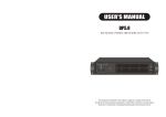
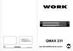
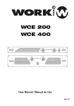
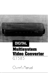
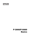
P R O F E S S I O N A L
A U D I O
USER'S MANUAL
USER'S MANUAL
DXI8200
8 CHANNEL CL ASS-D AMPLIFIER
PROTECT
PROTECT
PROTECT
PROTECT
CLIP
CLIP
CLIP
CLIP
SIGNAL
SIGNAL
SIGNAL
SIGNAL
DXI 8200
8 CHANNEL
CLASS-D AMPLIFIER
POWER
ON
MUTE
PARALLEL
MUTE
BRIDGE
MUTE
PARALLEL
MUTE
BRIDGE
MUTE
MUTE
PARALLEL BRIDGE
MUTE
PARALLEL
MUTE
BRIDGE
POWER
The information contained in this manual is subject to change without notice.
No part of this manual may be reproduced or transmitted in any form or by any means,
electronic or mechanical, including photocopying and recording of any kind.
DXI8200 8 CHANNEL CLASS-D AMPLIFIER
LIMITED WARRANTY
THE WARRANTY
For a period of One (1) year from the date of delivery to the original purchaser (as shown on the original invoice or sales
receipt), NOVA International Group Limited warrants to the ORIGINAL OWNER of each product (provided it was
purchased at an Authorized NOVA Dealer) that it is free of defects in materials and workmanship and that each product
will meet or exceed all factory published specifications for each respective model. NOVA agrees to repair or replace (at its
discretion) all defective parts at no charge for labor or materials; subject to following provisions:
DXI8200 8 CHANNEL CLASS-D AMPLIFIER
The information furnished in this manual does not include all of the details of design and engineering of this
particular product; not does it cover every possible application or situation concerning its usage, which may
occur during the installation, operation or maintenance of said NOVA product.
IMPORTANT
THE PRODUCT REQUIRES
CLASS 2 OUTPUT WIRING.
WARRANTY VIOLATIONS
NOVA shall take no responsibility for repair or replacement as specified under this warranty, if the damaged product has
been subject to misuse, accident, neglect or failure to comply with normal maintenance procedures; or if the serial
number has been defaced, altered or removed. Nor will NOVA accept responsibility for, or resulting from, improper
alterations or unauthorized parts or repairs. This warranty does not cover any damage to speakers or any other
consequential damage resulting from breach of any written or implied warranty.
NOVA WARRANTY PROVISIONS
NOVA will remedy any defect, regardless of the reason for failure (except as excluded ) by repair, or replacement. NOVA
will remedy the defect and ship the product within a reasonable time after receipt of the defective product at an NOVA
Authorized Service Center.
TO OBTAIN WARRANTYSERVICE
In the event that an NOVA product requires service, the Owner must contact NOVA or an Authorized NOVA Service
Center to receive an R.A.N. ( Return Authorization Number) and instructions on how to return the product to the NOVA
Authorized Service Center, or to the factory. NOVA (or its Authorized Service Center) will initiate corrective repairs upon
receipt of the returned product. Please save original carton and all the packing materials in case shipping is required. All
products being returned to the factory or service center for repairs must be shipped pre-paid.
CAUTION
TO PREVENT ELECTRIC SHOCK, DO NOT
REMOVE TOP OR BOTTOM COVERS. NO
USER SERVICEABLE PARTS INSIDE. REFER
SERVICING TO QUALIFIED SERVICE
PERSONNEL. DISCONNECT POWER CORD
BEFORE REMOVING REAR PANEL COVER
TO ACCESS GAIN SWITCH.
If the repairs made by NOVA or the NOVA Authorized Service Center are not satisfactory, Owner is instructed to give
written notice to NOVA. If the defect or malfunction remains after a reasonable amount of attempts by NOVA to remedy
the defect or malfunction, the Owner shall then have the option to elect either a refund or replacement of said NOVA
product free of charge. The refund shall be an amount equal to but not greater than the actual purchase price, not
including any taxes, interest, insurance, closing costs and other finance charges (minus reasonable depreciation on the
product). If a refund is necessary, the Owner must make the defective or malfunctioning product available to NOVAfree
and clear of all liens or other restrictions.
MODIFICTTIONS OF EQUIPMENT
NOVA reserves the right to modify or change equipment (in whole or part) at any time prior to delivery thereof, in order to
include therein electrical or mechanical improvements deemed appropriate by NOVA; but without incurring any liability to
modify or change any equipment previously delivered, or to supply new equipment in accordance with any earlier
specifications.
DISCLAIMER OF CONSEQUENTIAL AND INCIDENTAL DAMAGES
YOU,THE OWNER, ARE NOT ENTITLED TO RECOVER FROM NOVA ANY INCIDENTAL DAMAGES RESULTING
FROM ANY DEFECT IN THE NOVA PRODUCT. THIS INCLUDES ANY DAMAGE TO ANOTHER PRODUCT OR
PRODUCTS RESULTING FROM SUCH ADEFECT.
WARRANTY ALTERATIONS
No person has the authority to enlarge, amend, or modify this Warranty. This Warranty is not extended by the length of
time which the Owner is deprived of the use of product. Repairs and replacement parts provided pursuant to the
Warranty shall carry only the non-expired portion of the Warranty.
Shock Hazard - Do Not Enter
Choc Hasard - N*entrent
Schocke Hazard - Test Nicht
Betrete
Urto Hazard - Do Non Entrano
WARNING
TO REDUCE THE RISK OF ELECTRIC
SHOCK, DO NOT EXPOSE THIS
EQUIPMENT TO RAIN OR MOISTURE!
Magnetic Field
CAUTION: Do not locate sensitive high-gain equipment such as preamplifiers or tape
decks directly above or below this unit. Because this amplifier has a high power density, it
has a strong magnetic field which can induce hum into unshielded devices that are located
nearby. This field is strongest just above and below the unit. If an equipment rack is used,
we recommend locating the amplifier(s) at the bottom of the rack and the preamplifier or
other sensitive equipment at the top.
The lightning bolt triangle is
used alert the user to the
risk of electric shock.
The exclamation point triangle is used
to alert the user to important operating
and/or maintenance instructions.
Printed on
recycled paper.
THIS STATEMENT OF WARRANTY SUPERSEDES ALL OTHERS CONTAINED IN THIS MANUAL
Page 1
Reference Manual
Reference Manual
Page 2
DXI8200 8 CHANNEL CLASS-D AMPLIFIER
Introduction
Congratulations on your purchase of a DXI8200 audio power amplifier. We would like to
thank you for your confidence in us and our products.
All the components were specially selected. Although the amplifier was designed to allow
straightforward and uninterrupted operation, improper handling or incorrect installation
could damage the power amplifier.
Your amplifier represents the latest technology in power amplifier design. Please read this
manual carefully as it contains information vital to the safe operation of your amplifier.
DXI8200 8 CHANNEL CLASS-D AMPLIFIER
Front Panel
5
234
PROTECT
PROTECT
PROTECT
CLIP
CLIP
CLIP
SIGNAL
SIGNAL
SIGNAL
MUTE
MUTE
BRIDGE
MUTE
PARALLEL
MUTE
BRIDGE
MUTE
MUTE
PARALLEL BRIDGE
11
PROTECT
CLIP
SIGNAL
PARALLEL
10
MUTE
PARALLEL
MUTE
BRIDGE
POWER
Unpacking
Check the carton box and its contents immediately to see if there is any sign of damage.
Upon unpacking inspect the amplifier, if you detect any damage inform the forwarding
agentwithout delay and ask for the damage to be documented.
Claims can only be made against the forwarder agent by the consignee.
Be sure to save the carton and all packaging materials for the carrier's inspection.
It's a good idea to save the carton and packing material even if the amplifier has arrived in
good condition. Should you ever need to ship the unit back to service office, or one of its
Service Center. Using only the original factory packaging will be the best way to save the
unit from carrier negligence.
Installation/Mounting
DXI8200 is 2- rack space units that can mount in a standard 19" rack. Four front panel
mounting holes are provided.
Rear mounting ears give additional support especially important in mobile sound systems.
The unit should not to be installed in a location with:
Too high ambient temperature, dust build-up or excessive humidity;
Fog machines output's oriented to the area of the amplifier;
Exhaust air ventilators and similar units near the area of the amplifier;
With permanent vibrations;
With excessive induction or magnetic fields due to tranformers and transmitters;
The Show Always Goes On
DXI8200 is completely protected against every possible error in operation and is designed
to work under every condition. It gives you maximum power with maximum safety and
increases long-term reliability. Anticipating potential problems at the design stage means
your show always goes on!
67
89 1
1
1. POWER switch and indicator
Turns power to the unit on or off. The indicator lights green when the power is on.
2. PROTECT indicator
When the protection system is active, the indicator lights red. When this is lit, the amplifier or
power supply is auto-matically shut down, and no sound will be output from the speakers.
3. CLIP indicator
This indicator will light red when the output power exceeds 100 W for an 8
a 4 load. When this is lit, the limiter will automatically operate.
load or 200 W for
4. SIGNAL indicator
This indicator will light green when the output level exceeds 2 Vrms. (This will light at 0.5 W or
greater for an 8 load, 1W or greater for a 4 load.)
5. Attenuator
These are detented knobs that attenuate the input signal of each channel ( A~H ) over 41
steps in a range of 0 dB ~- dB.
NOTE. To operate these knobs, use a slotted screwdriver with a blade no wider than 5.5 mm.
6. MUTE indicator
This will light red when mute is activated.
7. MUTE switch
This turns muting on/off for each channel. Use a thin rod to turn muting on/off.
8. PARALLEL indicator
This will light orange when the rear panel MODE switch is set to PARALLEL.
9. BRIDGE indicator
This will light orange when the rear panel MODE switch is set to BRIDGE.
Page 3
Reference Manual
Reference Manual
Page 4
DXI8200 8 CHANNEL CLASS-D AMPLIFIER
10. Fan intake grill filter
One grill with foam filter is located on the front panel to prevent dust from entering the
amplifier. For easy cleaning of the filter the grill is removable by simply pulling it off. The foam
filter should always be used. The fan's variable speed control ensure low noise operation and
adapt the quantity of air required from the actual temperature inside the unit.
Thanks to this advanced system low noise is guarantee. Do not block this intake!
11. Rack mounting ears
Two front panel mounting holes are provided on each mounting ear.
DXI8200 8 CHANNEL CLASS-D AMPLIFIER
3. SPEAKERS connectors
These are barrier strip type speaker output connectors.
NOTE
If using BRIDGE mode, connect the speakers to the +
the - pin of channels B/ D/F/H.
pin of channels A/C/E/G and
Do not connect the pin marked NC located in the center of the bottom row of the barrier
strip connectors.
Rear Panel
2
4
3
3
1
4. AC inlet
Connect this to the socket end of the included AC power cable . Connect the plug end of the
AC power cable to an AC outlet of the correct voltage.
1. INPUT connectors
These are balanced input connectors. The included Eurob-lock connectors can be used to
make connections here.
2. MODE switches
These specify the amplifier
s operation mode for each two channels.
STEREO mode
Each channel (A~H) will operate independently.
BRIDGE mode
The amplifiers will be bridged for pairs of adjacent channels (A-B, C-D, E-F, G-H), obtaining a
high-power output.
PARALLEL mode
The input signals will be input to the adjacent channels (A-B, C-D, E-F, G-H) as well.
Page 5
Reference Manual
Reference Manual
Page 6
DXI8200 8 CHANNEL CLASS-D AMPLIFIER
Speakers can be connected to the DXI8200 using the following three mode settings. The
total load impedance of the speakers that can be connected will depend on the mode
setting. Do not use a setup that has a lower impedance than the minimum values shown
below.
SPECIFICATIONS
DXI8200
MODEL
Max output power
rms at 1 kHz and 0.1 % THD
STEREO mode
If the rear panel MODE switch is set to STEREO, each channel will operate independently. You
can use the front panel attenuators to adjust the attenuation for each channel independently.
NOTE
DXI8200 8 CHANNEL CLASS-D AMPLIFIER
Total speaker impedance must be 4 ~8
rms at 20Hz-20kHz and 0.1 % THD
1 kHz
20ms Burst
4
per channel (Watt)
220W x8
8
per channel (Watt)
120W x8
8
BRIDGE
350W x4
4
per channel (Watt)
160W x8
8
per channel (Watt)
90W x8
8
BRIDGE
320W x8
4
per channel (Watt)
180W x8
8
per channel (Watt)
100W x8
8
BRIDGE
360W x8
+24dBu
Maximum Input Level
PARALLEL mode
(balanced)
20k
(unbalanced)
Input Sensitivity (dBu)
If the rear panel MODE switch is set to PARALLEL, the input signals will be input to the adjacent
channels (A-B, C-D, E-F, G-H) as well. Either of adjacent two channels can be used as an input
connector. You can use the front panel attenuators to adjust the attenuation for each channel
independently.
NOTE
40k
Input Impedance
8
Att. max
0.775V
Input sensitivity
S/N Ratio
A-weighted
THD+N
1kHz, half power, 4
Frequency Response
1W, 8
Channel Separation
1kHz, half power, 8
95dB
0.5%
20Hz-20kHz +0dB -1.5dB
Att.
max, input 600 shunt
Total speaker impedance must be 4 ~8
Controls
55dB
Front Panel
POWER switch
MUTE switch (push ON/push OFF) x 8
Attenuator (41positon) x 8
BRIDGE mode
Rear Panel
If the rear panel MODE switch is set to BRIDGE, the amplifiers will be bridged between adjacent
pairs of channels (A-B, C-D, E-F, G-H), and the IPA8200 will operate as a high-power amplifier.
Either of adjacent two channels can be used as an input connector. Use the front panel channel
A/C/E/G attenuators to adjust the attenuation.
NOTE
Total speaker impedance must be 8 ~16
Connectors
Input
Indicators
CLIP x 8 (Red), SIGNAL x 8 (Green), MUTE x 8 (Red),
PARALLEL x 4 (Orange), BRIDGE x 4 (Orange)
Load Protection
POWER switch on/off
Thermal
Power Supply Protection
Thermal
Limiter Circuit
Clip limiting
AC Power Requirement
Dimensions ( W x D x H )
Net Weight
Gross Weight
Source:
Channel B
Source:
Channel A
STEREO mode
Page 7
MUTE
BRIDGE
Source:
Channel A
Source:
Channel A
PARALLEL mode
MUTE
MUTE
PARALLEL
PARALLEL
Source:
Channel A
BRIDGE mode
Reference Manual
Output mute (heatsink temp
80
)
Power supply shutdown
Power supply shutdown (heatsink temp
Limiting level
100W @8
85
)
or 150W@4
800W
Unit ( mm )
Packing ( mm )
Weight ( kg )
Output mute
Power supply shutdown
~220-240 50/60Hz
Power Consumption
MUTE
AC inlet x 1
POWER x 1 (Green), PROTECT x 8 (Red),
Over current
PARALLEL
Barrier strip/ch
Power
Amplifier Protection
MUTE
Euroblock (balanced)/ch
Output
DC-fault
BRIDGE
MODE switch (STEREO/BRIDGE/PARALLEL) x 4
483 x 355 x 89
570 x 480 x 165
8
10
The DXI8200 amplifier has an automatic power factor correction system for a perfect main
network interface. The amplifier is a resistive load for the main network, minimizing the reactive
power and the harmonic distortion on the current. The system allows performance to be
maintained even in circumstances of varying the mains voltage.
Reference Manual
Page 8
DXI8200 8 CHANNEL CLASS-D AMPLIFIER
Service
This unit has very sophisticated circuitry and should only be serviced by a fully trained
technician.
This is why each unit bears the following label:
To prevent electric shock, do not remove covers. No user serviceable parts inside. Refer
servicing to a qualified technician.
Worldwide Service
Service may be obtained from your local authorized service center. To obtain service, simply
present your sales receipt as proof of purchase along with the defective unit to an authorized
service center. They will handle the necessary paperwork and repair. Remember to transport
your unit in the original factory packaging.
1. When sending a NOVA product to the authorized service center for service, be sure to fill out
the service information form that is enclosed at the end of this manual and include it inside
your unit's shipping pack. Do not send the service information form separately.
2. To ensure the safe transportation of your unit to the authorized service center, ship it in an
original factory-packing container.
NOVA Products
Service Information Form
Owner's Name:
Shipping address:
Street:
City:
Zip Code:
Country:
Phone Number:
Email:
MODEL:
NUMBER:
Place of Purchase:
Name of Dealer:
Full Address:
DATE OF PURCHASE:
Fax Number:
SERIAL:
Nature of the problem
(Be sure to describe the conditions that existed when the problem occurred and what
attempts were made to correct it.)
3. Do not ship the unit in any kind of rack. Ignoring this warning may result in extensive damage
to the unit and the equipment rack. Accessories are not needed. Do not send the instruction
manual, cables and any other hardware.
Other equipment in your system
WEEE Mark
If you want to dispose of this product, do not mix with general
household waste. There are separate collection systems for used
electronic products in accordance with legislation under the WEEE
Directive (Directive 2002/96/EC) and is effective only within the
European Union.
Page 9
Reference Manual
If warranty has expired, payment method:
Cash
Check
card number:
Signature:
Visa
Master
Enclose this form with the defective unit. Do not mail separately.